

Page 1
Instruction Manual
IQ-MAN-140
L
Rev. F
May 2017
Rosemount
™
140/141/142
Contacting Conductivity Sensors
Page 2

asgkas
h
Page 3

Essential Instructions
Read this page before proceeding!
Emerson designs, manufactures and tests its products to meet many national and international stan-
dards. Because these sensors are sophisticated technical products, you MUST properly install, use,
nd maintain them to ensure they continue to operate within their normal specifications. The
a
following instructions MUST be adhered to and integrated into your safety program when installing,
using, and maintaining Rosemount products. Failure to follow the proper instructions may cause
any one of the following situations to occur: loss of life; personal injury; property damage; damage
to this sensor; and warranty invalidation.
• Read all instructions prior to installing, operating, and servicing the product.
• If you do not understand any of the instructions, contact your Emerson representative for
clarification.
• Follow all warnings, cautions, and instructions marked on and supplied with the product.
• Inform and educate your personnel in the proper installation, operation, and maintenance
of the product.
• Install your equipment as specified in the Installation Instructions of the appropriate
Instruction Manual and per applicable local and national codes. Connect all products to
the proper electrical and pressure sources.
• To ensure proper performance, use qualified personnel to install, operate, update,
program, and maintain the product.
• When replacement parts are required, ensure that qualified people use replacement parts
specified by Emerson. Unauthorized parts and procedures can affect the product's
performance, place the safe operation of your process at risk, and VOID YOUR WARRANTY.
Third-party substitutions may result in fire, electrical hazards, or improper operation.
• Ensure that all equipment doors are closed and protective covers are in place, except when
maintenance is being performed by qualified persons, to prevent electrical shock and
personal injury.
The information contained in this document is subject to change without notice.
CAUTION
Sensor/Process Application Compatibility
The wetted sensor materials may not be compatible with process composition and operating
conditions. Application compatibility is entirely the responsibility of the user.
CAUTION
Before removing the sensor, be absolutely certain the process pressure is reduced to 0 psig and the
process temperature is at safe level.
Page 4

About This Document
his manual contains instructions for installation and operation of the Rosemount
T
140/141/142 Contacting Conductivity Sensor
The following list provides concerning all revisions of this document.
Rev. Level Date Notes
F 05/17 Reformatted to reflect the latest Emerson documentation style
Specifications and Wiring Diagrams.
Page 5

Instruction Manual Table of Contents
LIQ-MAN-140 May 2017
Contents
Section 1: Specifications
1.1 Specifications ......................................................................................................1
Section 2: Installation
2.1 Unpacking and Inspection ...................................................................................5
2.2 Sensor Installation ...............................................................................................5
2.3 Installation - Rosemount 140 Sensor with Ball Valve Kit (PN 23724-00) ................5
2.4 Installation - Rosemount 141 Sensor ....................................................................6
2.5 Installation - Rosemount 142 Sensor ....................................................................7
Section 3: Wiring
3.1 Wiring for Rosemount 140/141/142 ....................................................................9
Section 4: Retracting and Inserting the Rosemount 140 Sensor
4.1 Retracting the Sensor ........................................................................................13
4.2 Inserting the Sensor...........................................................................................13
Section 5: Removing and Reinstalling the Rosemount 142 Sensor
5.1 Removing the Sensor .........................................................................................15
5.2 Reinstalling the Sensor.......................................................................................15
Section 6: Calibration and Maintenance
6.1 Calibrating the sensor........................................................................................17
6.2 Cleaning the Sensor ...........................................................................................21
6.3 Checking the Rosemount 140 Retraction Restraint ............................................21
6.4 Replacing Rosemount 140 Sensor Seal ...............................................................21
Section 7: Accessories
7.1 Accessories........................................................................................................23
Section 8: Troubleshooting
8.1 Troubleshooting ................................................................................................25
Table of Contents i
Page 6

Table of Contents Instruction Manual
May 2017 LIQ-MAN-140
ii Table of Contents
Page 7

Instruction Manual Specifications
LIQ-MAN-140 May 2017
Section 1: Specifications
1.1 Specifications
Table 1-1: Rosemount 140 contacting conductivity sensor specifications
Wetted Materials
Electrodes 316 stainless steel
Body 316 stainless steel
Insulator PEEK
O-rings Viton
Temperature range
Standard 32 °F to 302 °F (0 °C to 150 °C) maximum
High temperature 32 °F to 392 °F (0 °C to 200 °C) maximum
Pressure
100 psig (791 kPa abs) maximum
Maximum retraction pressure
100 psig (791 kPa abs)
Vacuum
At 1.6 in. Hg (5.2 kPa) air leakage is less than 0.005 SCFM (0.00014 m3/min)
Junction box
cast aluminum
Process connection
1 in. MPT through 1inch full port ball valve (retractable)
Weight/Shipping Weight
5 lb /6 lb (2.5 kg / 3.0 kg)
Weights rounded up to nearest whole lb or 0.5 kg
Specifications 1
Page 8

Specifications Instruction Manual
May 2017 LIQ-MAN-140
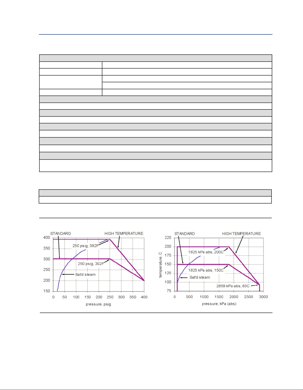
Table 1-2: Rosemount 141 contacting conductivity sensor specifications
Wetted Materials
Electrodes 316 stainless steel
ody
B
Insulator PEEK
O-rings Viton
Temperature and pressure
See Figure 1-1
Vacuum
At 1.6 in. Hg (5.2 kPa) air leakage is less than 0.005 SCFM (0.00014 m3/min)
Junction box
cast aluminum
Process connection
¾ in. MPT
Weight/Shipping Weight
2 lb / 3 lb (1.0 kg / 1.5 kg)
Weights rounded up to nearest whole lb or 0.5 kg
16 stainless steel
3
2 Specifications
Page 9
Instruction Manual Specifications
LIQ-MAN-140 May 2017
Table 1-3: Rosemount 142 contacting conductivity sensor specifications
Wetted Materials
Electrodes 316 stainless steel
ody
B
Insulator PEEK (high temperature option)
O-rings Viton
Temperature and Pressure
See Figure 1-1
Vacuum
At 1.6 in. Hg (5.2 kPa) air leakage is less than 0.005 SCFM (0.00014 m3/min)
Junction box
cast aluminum
Process connection
¾ in. MPT
Weight/Shipping Weight
2 lb/3 lb (1.0 kg / 1.5 kg)
Weights rounded up to nearest whole lb or 0.5 kg
16 stainless steel
3
PCTFE (low temperature option)
Table 1-4: Specifications for PN 23724-00 ball valve kit
Wetted Materials
316 stainless steel except Teflon® seat and seals in ball valve
Figure 1-1 Rosemount 141 and 142 sensor pressure/temperature graphs
Heading title 3
Page 10

Specifications Instruction Manual
May 2017 LIQ-MAN-140
4 Specifications
Page 11

Instruction Manual Installation
LIQ-MAN-140 May 2017
Section 2: Installation
2.1 Unpacking and Inspection
Inspect the outside of the carton for any damage. If damage is detected, contact the carrier
immediately. Inspect the instrument and hardware. Make sure all items in the packing list are
present and in good condition. Notify the factory if any part is missing.
2.2 Sensor Installation
Keep 1/4 in. (6 mm) clearance between electrodes and piping. The electrodes must be completely
submerged in the process liquid, i.e., to the level of the threaded connection. See Figure 2-1 for
recommended orientation.
If the sensor is installed in a side stream with the sample draining to open atmosphere, bubbles
may accumulate on the electrodes. Trapped bubbles will cause errors. As bubbles accumulate, the
conductivity reading drops. To control bubble formation, apply a small amount of back pressure to
the drain.
Figure 2-1 Sensor orientation
2.3 Installation - Rosemount 140 Sensor with Ball Valve
Kit (PN 23724-00) *
1. Install the sensor in either a 1 in. NPT weldalet or in a 1 in. pipe tee.
2. Remove the plastic shipping cap from the sensor.
3. Screw the 1 in. hex nipple into the weldalet or pipe tee. See Figure 2-2. Use pipe tape on
the threads.
4. Position the sensor for easy access to the ball valve handle, sensor compression fitting nut,
and junction box.
5. Make sure the ball valve is in the fully open position.
6. Finger tighten the sensor compression fitting nut. Do not over tighten because the next
step is to press the sensor into the process pipe.
7. Insert the sensor tube until the sensor tip is no closer than 1 in. (25 mm) from the far wall
of the process pipe. See Figure 2-2.
8. Tighten the sensor compression fitting nut to hold the sensor tip in position.
* If the ball valve assembly is already in place and the process line is pressurized, refer to
Inserting the Sensor.
Installation 5
Page 12

Installation Instruction Manual
May 2017 LIQ-MAN-140
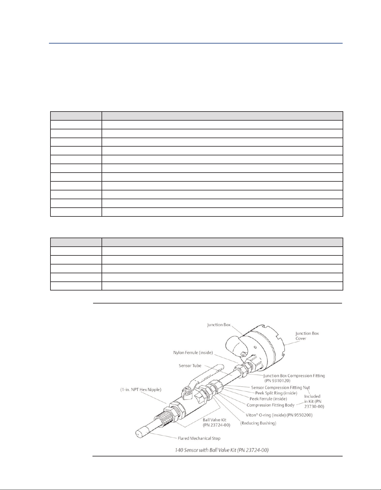
Figure 2-2 Installing the Rosemount 140 sensor with ball valve kit (PN 23724-00)
2.4 Installation - Rosemount 141 Sensor
1. Install the sensor in a 3/4 in. NPT weldalet or in a 1 in. pipe tee.
2. Remove the plastic shipping cap from the sensor.
3. Screw the sensor into the fitting. Use pipe tape on the threads. See Figure 2-3.
Figure 2-3 Installing Rosemount 141 sensor
6 Installation
Page 13

Instruction Manual Installation
LIQ-MAN-140 May 2017
2.5 Installation - Rosemount 142 Sensor
1. Install the sensor in a 3/4 in. NPT weldalet or in a 1 in.pipe tee. See Figure 2-4.
2. Remove the plastic shipping cap from the sensor.
3. Screw the sensor into the fitting. Use pipe tape on the threads. DO NOT tighten the sensor
compression fitting until the sensor is correctly positioned.
4. If necessary, loosen the sensor compression fitting and position the sensor so that the tip
of the sensor is at least 1 in. (25 mm) from the far wall of the pipe.
5. Tighten the compression fitting using the procedure shown in Figure 2-2.
Figure 2-4 Installing Rosemount 142 sensor
Installation 7
Page 14

Installation Instruction Manual
May 2017 LIQ-MAN-140
8 Installation
Page 15

Instruction Manual Wiring
LIQ-MAN-140 May 2017
Section 3: Wiring
3.1 Wiring for Rosemount 140/141/142
For other wiring diagrams not shown below, please refer to the Liquid Transmitter Wiring Diagrams.
All Rosemount 140 series sensors have a junction box mounted on the back of the sensor. Wiring
connections in the junction box are shown in Figure 3-1.
Rosemount 141 and 142 sensors have one gray wire (shown). The Rosemount 140 sensor has two
gray wires attached to the terminal.
Figure 3-1: Sensor junction box wiring. Terminals in the junction box are not numbered.
Figure 3-2: Wire color and connections in sensor
Wiring 9
Page 16

Wiring Instruction Manual
May 2017 LIQ-MAN-140
Figure 3-3: Rosemount 140/141/142 Sensor Wiring to Rosemount 1056, 56, and 1057
Transmitters
Figure 3-4: Rosemount 140/141/142 Sensor Wiring to Rosemount 1066 Transmitter
10 Wiring
Page 17

Instruction Manual Wiring
LIQ-MAN-140 May 2017
Figure 3-5: Rosemount 140/141/142 Sensor Wiring to Rosemount 5081 Transmitter
Wiring 11
Page 18

Wiring Instruction Manual
May 2017 LIQ-MAN-140
12 Wiring
Page 19

Instruction Manual Retracting and Inserting the Rosemount 140 Sensor
LIQ-MAN-140 May 2017
Section 4: Retracting and Inserting the
Rosemount 140 Sensor
CAUTION
Rosemount 140 sensors are retractable. Before retracting the sensor, be absolutely certain the process
pressure is less than 100 psig (791 kPa abs) and the process temperature is at a safe level!
4.1 Retracting the Sensor
1. Push in on the sensor junction box and slowly loosen the sensor compression fitting nut by
reversing the sensor tightening procedure illustrated in Figure 2-2.
2. When the sensor compression nut is completely unscrewed, slowly ease the sensor out
until the flared tip of the electrode rests firmly within the body of the compression fitting
body.
3. Close the ball valve completely.
CAUTION
Before removing the sensor be sure the ball valve is completely closed.
4. Unscrew the compression fitting body from the reducing bushing and remove the sensor
from the ball valve assembly.
4.2 Inserting the Sensor
CAUTION
Make sure process O-ring is clean, lubricated, and in place before installing sensor. Replace if worn.
1. Do not open the ball valve.
CAUTION
The system pressure must be less than 100 psig (791 kPa).
2. Thread the sensor compression fitting body into the reducing bushing in the rear of the
ball valve and tighten.
Note: Do not push past this point. Damage to the sensor could result.
WARNING
If the sensor comes free of the valve, refer to Figures 2-2 and 7-1 and verify that the valve and
associated fittings are as shown. Do not proceed until the sensor is correctly restrained.
3. Slowly open the valve.
WARNING
Stand clear of the sensor.
Retracting and Inserting the Rosemount 140 Sensor
13
Page 20

Retracting and Inserting the Rosemount 140 Sensor Instruction Manual
May 2017 LIQ-MAN-140
1. Insert the sensor up to the desired insertion depth and turn the sensor compression fitting
nut until it is finger tight.
2. Position the entire sensor for easy access to the ball valve handle, sensor compression
fitting nut and J-box terminal block.
3. Tighten sensor compression fitting nut.
CAUTION
For initial installation of the sensor, tighten the compression fitting nut 1-1/4 turns after finger tight. If
it is a reinstallation, turn no more than 1/4 to 1/2 additional turns.
14 Retracting and Inserting the Rosemount 140 Sensor
Page 21

Instruction Manual Removing and Reinstalling the Rosemount 142 Sensor
LIQ-MAN-140 May 2017
Section 5: Removing and Reinstalling the
Rosemount 142 Sensor
5.1 Removing the Sensor
WARNING
efore removing the sensor, be absolutely certain that the process pressure is reduced to 0 psig and
B
the process temperature is lowered to a safe level!
1. Reduce process temperature and pressure to a safe level. If necessary drain the process
line.
2. Loosen the sensor compression fitting and slowly slide the sensor from the pipe fitting or
weldalet.
5.2 Reinstalling the Sensor
1. Slide the sensor into the process fitting and position the sensor the way it was originally
installed.
CAUTION
Be sure the sensor is in the original position. The sensor tube takes a permanent set and could become
weakened if the new set is adjacent to the original set.
2. Tighten the sensor compression fitting 1/4 to 1/2 turn after it is finger tight.
Removing and Reinstalling the Rosemount 142 Sensor 15
Page 22

Retracting and Inserting the Rosemount 140 Sensor Instruction Manual
May 2017 LIQ-MAN-140
16 Removing and Reinstalling the Rosemount 142 Sensor
Page 23

Instruction Manual Calibration and Maintenance
LIQ-MAN-140 May 2017
Section 6: Calibration and Maintenance
6.1 Calibrating the sensor
osemount 140/141/142 sensors are not calibrated at the factory. The cell constant on the label is
R
a nominal value only. The true cell constant can differ from the nominal value by as much as ±5%.
For improved accuracy, calibrate the sensor using either a solution of known conductivity or a
referee meter and sensor. If using a standard solution, choose one having conductivity in the
recommended operating range for the sensor cell constant.
Do not use standard solutions having conductivity less than about 100 µS/cm for calibration. They
are susceptible to contamination by atmospheric carbon dioxide, which can alter the conductivity
by a variable amount as great as 1.2 µS/cm (at 25 °C). Because 0.01/cm sensors must be calibrated
in low conductivity solutions, they are best calibrated against a referee meter and sensor in a closed
system. For more information about calibrating refer to
6.1.1 Calibrating using a standard solution
Application Data Sheet.
If using a standard solution, choose one having conductivity in the recommended operating range
for the sensor cell constant.
1. Immerse the rinsed sensor in the standard solution and adjust the transmitter reading to
match the conductivity of the standard.
2. For an accurate calibration:
a. Choose a calibration standard near the midpoint of the recommended conductivity
range for the sensor.
b. Do not use calibration standards having conductivity less than 100 µS/cm.
c. Turn off automatic temperature compensation in the transmitter.
d. Use a standard for which the conductivity as a function of temperature is known.
e. Use a good quality calibrated thermometer with an error rate less than ±0.1 °C to
measure the temperature of the standard.
f. Follow good laboratory practice. Rinse the beaker and sensor at least twice with
standard. Be sure the rinse solution reaches between the inner and outer electrodes by
tapping and swirling the sensor while it is immersed in the standard.
g. Be sure air bubbles are not trapped between the electrodes. Place the sensor in the
standard and tap and swirl to release bubbles. Note the reading and repeat. If readings
agree, no trapped bubbles are present. Repeat until two subsequent readings agree.
Calibration and Maintenance 17
Page 24

Calibration and Maintenance Instruction Manual
May 2017 LIQ-MAN-140
6.1.2 Calibrating using a reference meter and sensor
1. Connect the process sensors and reference sensor in series and allow the process liquid
to flow through all sensors.
2. Calibrate the process sensor by adjusting the process transmitter reading to match the
conductivity measured by the reference meter. See Figure 3-1 for the calibration setup.
Figure 3-1 In process calibration setup
NOTICE
The above figure shows two process sensors connected in series with a reference sensor. The horizontal
sensor orientation ensures good circulation of the process liquid past the electrodes. The staircase
orientatation provides an escape path for bubbles.
3. The method is ideal for calibrating the sensors used in low conductivity water (0.01/cm
cell constants) because the calibration system is closed and cannot be contaminated by
atmospheric carbon dioxide.
Following precautions are necessary for successful calibration:
1. If the normal conductivity of the process liquid is less than about 1.0 µS/cm, adjust the
conductivity so that it is near the upper end of the operating range.
The difference between the conductivity measured by the process and reference meter
usually has both a fixed (constant error) and relative (proportional error) component.
Because the cell constant calibration assumes the error is proportional only, calibration at
low conductivity allows the fixed component to have an outsized influence on the result.
For example, assume the only difference between reference meter and process sensor is
fixed and the process sensor always reads 0.002 µS/cm high. If the process sensor is
calibrated at 0.100 µS/cm, the new cell constant will be changed by 0.100/0.102 or 2%. If
the sensor is calibrated at 0.500 µS/cm, the change will be only 0.500/0.502 or 0.4%.
Calibration at higher conductivity produces a better result because it minimizes the effect
of the offset.
18 Calibration and Maintenance
Page 25

Instruction Manual Calibration and Maintenance
LIQ-MAN-140 May 2017
. Orient the sensors so that air bubbles always have an easy escape path and cannot get
2
trapped between the electrodes.
3. Turn off automatic temperature compensation in the transmitter.
Almost all process conductivity transmitter feature automatic temperature compensation
in which the transmitter applies one of several temperature correction algorithms to
convert the measured conductivity to the value at a reference temperature, typically 25 °C.
Although temperature correction algorithms are useful for routine measurements, they
should not be used during calibration.
There are two following reasons:
a. No temperature correction is perfect. If the assumptions behind the algorithm do not
perfectly fit the solution being measured, the temperature-corrected conductivity will
be in error.
b. If the temperature measurement itself is in error, the corrected conductivity will be in
error.
The purpose of calibrating the sensor is to determine the cell constant. To minimize the
error in the cell constant, all sources of avoidable error, e.g., temperature compensation
should be eliminated.
4. Keep tubing runs between the sensors short and adjust the sample flow as high as possible.
Short tubing runs and high flow ensure the temperature of the liquid does not change as
it flows from one sensor to another.
If the process temperature is appreciably different from ambient, high flow may not be
enough to keep the temperature constant. In this case, pumping sample at room
temperature from a reservoir through the sensors might be necessary. Because such a
system is likely to be open to atmosphere, saturate the liquid with air to prevent drift
caused by absorption of atmospheric carbon dioxide.
5. To prevent contamination of low conductivity (<1 µS/cm) process liquids, use clean tubing
to connect the sensors. To prevent drift caused desorption of ionic contaminants from
tube walls, keep the sample flow greater than 6 ft/sec (1.8 m/sec).
6.1.3 Calibrating using a grab sample
1. Use the grab sample method when it is impractical to remove the sensor for calibration or
to connect a reference sensor to the process line.
2. Take a sample of the process liquid, measuring its conductivity using a reference
instrument, and adjusting the reading from the process transmitter to match the measured
conductivity.
3. Take the sample from a point as close to the process sensor as possible.
4. Keep temperature compensation turned on. There is likely to be a lag time between
5. Be sure the reference and process instruments are using the same temperature correction
Calibration and Maintenance
sampling and analysis, so temperature is likely to change.
algorithm.
19
Page 26

Calibration and Maintenance Instruction Manual
May 2017 LIQ-MAN-140
. Grab sample calibration should be used only when the conductivity is fairly high.
6
a. The temperature compensation algorithm will most likely be linear slope.
b. Confirm that both instruments are using the same temperature coefficient in the linear
slope calculation.
c. If the reference meter does not have automatic temperature correction, calculate
the conductivity at 25 °C using the equation:
Where: C25 = the conductivity at 25 °C
Ct = the conductivity at t °C
α = the temperature co-efficient expressed as a decimal fraction.
d. Confirm the temperature measurements in both the process and reference instruments
are accurate, ideally to within ±0.5 °C.
e. Follow good laboratory practice when measuring the conductivity of the grab sample.
- Rinse the beaker and sensor at least twice with sample. Be sure the rinse solution
reaches between the inner and outer electrodes by tapping and swirling the
sensor while it is immersed in the sample.
- Be sure air bubbles are not trapped in the sensor. Place the sensor in the sample
and tap and swirl to release bubbles. Note the reading. Then, remove the sensor
and return it to the sample. Tap and swirl again and note the reading. If the two
readings agree, trapped bubbles are absent. If they do not agree, bubbles are
present . Continue the process until two subsequent readings agree.
- While making the measurement, do not allow the sensor to touch the sides and,
particularly, the bottom of the beaker. Keep at least 1/4 in. (6 mm) clearance.
f. Be sure to compensate for process conductivity changes that might have occurred
while the grab sample was being tested. Rosemount conductivity transmitters
(Rosemount transmitter models 1056, 1066, and 56) do this automatically. They save
the value of the process conductivity at the time the sample was taken and use that
value to calculate the new cell constant when the user enters the result of the grab
sample test. Older transmitters do not remember the process conductivity value.
Therefore, the user must enter a value adjusted by an amount proportional to the change
in the process conductivity. For example, suppose the process conductivity is 810 µS/cm
when the sample is taken and 815 µS/cm when the test result is entered. If the grab
sample conductivity is 819 µS/cm, the user should enter (815/810) × 819 or 824 µS/cm.
20 Calibration and Maintenance
Page 27

Instruction Manual Calibration and Maintenance
LIQ-MAN-140 May 2017
6.2 Cleaning the Sensor
Use a warm detergent solution and a soft brush or pipe cleaner to remove oil and scale. Isopropyl
alcohol can also be used to remove oily films. Avoid using strong mineral acids to clean
onductivity sensors.
c
6.3 Checking the Rosemount 140 Retraction Restraint
The integrity of the Rosemount 140 will become compromised is the flared tip of the electrode is
allowed to blow out against the compression fitting body. In the even a blowout occurs, replace
the sensor.
6.4 Replacing Rosemount 140 Sensor Seal
If the process seal is leaking owing to a pitted or uneven sensor tube, a replacement sensor is
required. If the sensor tube surface is smooth and clean yet the process seal is leaking, the process
O-ring is damaged and requires replacement according to the following procedure. Replacement
parts can be obtained from the Process Fitting Rebuild Kit (PN 23731-00).
1. The junction box with attached compression fitting body, nut and compression fitting must
be recovered from the sensor for reuse. Unscrew the junction box cover and set aside. Mark
and disconnect the electrical connections from the terminal block. Remove the junction
box compression fitting nut from the compression fitting body and separate the junction
box from the sensor tube.
2. Remove the nylon ferrule and snap ring (discard both). Remove and save the junction box
compression fitting nut.
3. Slide off the sensor compression fitting nut and set aside for reuse. Slide off the remaining
PEEK ferrule and split ring (discard both).
4. Remove the sensor compression fitting body and replace the Viton O-ring. Lubricate the
O-ring with the barium based lubricant provided.
5. Wrap the threads of the sensor compression fitting body with pipe tape and slide the body
on to the sensor tube.
6. Slide on a new PEEK ferrule, beveled side facing the electrode tip, and a new PEEK split ring,
flared end towards electrode tip. Slide on the sensor compression fitting nut and thread it
onto the compression fitting body. Finger tighten.
7. Reinstall the J-box on the sensor tube. Finger tighten the J-box compression fitting nut.
Use a wrench to turn the nut a 1/4 to 1/2 additional turn.
Calibration and Maintenance 21
Page 28

Calibration and Maintenance Instruction Manual
May 2017 LIQ-MAN-140
22 Calibration and Maintenance
Page 29
Instruction Manual Accessories
LIQ-MAN-140 May 2017
Section 7: Accessories
7.1 Accessories
Table 7-1 Rosemount 140/141/142 Sensor accessories information
Part Number Description
3550-00
2
9200275 Connecting cable, unterminated, specify length
23747-00 Connecting cable, terminated, specify length
05010781899
05010797875
05010782468
05010783002
05000705464
05000709672
05010782147
05010782026
unction box for remote cable connection
J
Conductivity standard SS-6, 200 µS/cm, 32 oz. (0.95 L)
Conductivity standard SS-6A, 200 µS/cm, 1 gal (3.78 L)
Conductivity standard SS-5, 1000 µS/cm, 32 oz (0.95 L)
Conductivity standard SS-5A, 1000 µS/cm, 1 gal (3.78 L)
Conductivity standard SS-1, 1409 µS/cm, 32 oz (0.95 L)
Conductivity standard SS-1A, 1409 µS/cm, 1 gal (3.78 L)
Conductivity standard SS-7, 5000 µS/cm, 32 oz (0.95 L)
Conductivity standard SS-7A, 5000 µS/cm, 1 gal (3.78 L)
Table 7-2 Rosemount 140 Sensor accessories information
Part Number Description
23724-00 Ball valve kit
23730-00 Process compression fitting, ¾ inch NPT
23731-00 Process fitting rebuild kit
9310120 Junction box compression fitting
9550200 O-ring® 2-116, Viton®
Figure 7-1: Rosemount 140 with Ball Valve Kit (PN 23724-00)
Accessories 23
Page 30

Accessories Instruction Manual
May 2017 LIQ-MAN-140
Table 7-2 Rosemount 142 Sensor accessories information
Part Number Description
33107-01 Compression fitting, ¾ in.
9310063 Ferrule, ¾ in.
9310066 Compression nut, ¾ in.
24 Accessories
Page 31

Instruction Manual Troubleshooting
LIQ-MAN-402 May 2017
Section 8: Troubleshooting
8.1 Troubleshooting
Table 8-1: Troubleshooting
Trouble Probable Cause Remedy
Wiring is incorrect. Verify wiring.
Temperature element is open or shorted. Check temperature element for open or short
Off-scale reading
Sensor is not in process stream. Be sure sensor is completely submerged in
Sensor has failed. Perform isolation checks. See Figure 8-2
circuits. See Figure 8-1
process stream.
Sensor is improperly installed in process
Noisy reading
Reading seems wrong (lower
or higher than expected)
Sluggish response Electrodes are fouled. Clean electrodes.
stream.
Bubbles trapped in sensor. Be sure sensor is properly oriented in pipe or
Wrong temperature correction algorithm. Check that temperature correction is appro-
Wrong cell constant. Verify that the correct cell constant has been
Sensor is installed in dead area in piping Move sensor to a location more representative
Be sure sensor is completely submerged in
process stream.
flow cell. See
to flow cell.
priate for the sample. See transmitter manual
for more information.
entered in the analyzer and that the cell
constant is appropriate for the conductivity of
the sample. See transmitter manual.
of the process liquid.
Figure 2-1. Apply back pressure
Note: For any repair or warranty inquiries please contact our Customer Care group.
Troubleshooting 25
Page 32

Troubleshooting Instruction Manual
May 2017 LIQ-MAN-402
8.1.1 Checking the temperature element
Disconnect leads and measure resistance shown. The measured resistance should be close to the
value in the table.
Figure 8-1 Checking the temperature element
8.1.2 Checking the continuity and leakage
Disconnect electrode leads and measure resistance and continuity as shown. Sensor must be dry
when checking resistance between electrode leads.
Figure 5-2 Checking the continuity and leakage
Temperature
(°C)
0 100.0 29.49k 351K
10 103.9 18.79k 208K
20 107.8 12.26K 127K
30 111.7 8194 79.4K
40 115.5 5592 51.0K
50 119.4 3893 33.6K
Resistance in ohms
Pt 100 10K NTC 100K NTC
26 Troubleshooting
Page 33

Instruction Manual Accessories
LIQ-MAN-402 May 2017
Accessories 27
Page 34

LIQ-MAN-140
Rev. M
May 2017
www.Emerson.com/RosemountLiquidAnalysis
Youtube.com/user/Rosemount
Twitter.com/Rosemount_News
Emerson Automation Solutions
8200 Market Blvd.
Chanhassen, MN 55317,
USA
Tel +1 800 999 9307
Fax +1 952 949 7001
Liquid.CSC@Emerson.com
Analyticexpert.com
facebook.com/Rosemount
©2017 Emerson Automation Solutions. All rights reserved.
The Emerson logo is a trademark and service mark of Emerson Electric Co. Rosemount is a mark of
one of the Emerson family of companies. All other marks are the property of their respective
owners.
The contents of this publication are presented for information purposes only, and while effort has
been made to ensure their accuracy, they are not to be construed as warranties or guarantees,
express or implied, regarding the products or services described herein or their use or applicability.
All sales are governed by our terms and conditions, which are available on request. We reserve the
right to modify or improve the designs or specifications of our products at any time without notice.
 Loading...