

Page 1
Instruction Manual
LIQ-MAN-1057
ev. D
R
April 2017
Rosemount
™
1057
Three-Input Intelligent Analyzer
Page 2

Essential Instructions
Read this page before proceeding
You
A
Page 3

Essential Instructions
Read this page before proceeding
Your instrument purchase from Emerson is one of the finest available for your particular application. These instruments have been
designed, and tested to meet many national and international standards. Experience indicates that its performance is directly related to the quality of the installation and knowledge of the user in operating and maintaining the instrument. To ensure their continued operation to the design specifications, personnel should read this manual thoroughly before proceeding with installation,
commissioning, operation, and maintenance of this instrument. If this equipment is used in a manner not specified by the manufac-
urer, the protection provided by it against hazards august be impaired.
t
• Failure to follow the proper instructions august cause any one of the following situations to occur: Loss of life; personal
injury; property damage; damage to this instrument; and warranty invalidation.
• Ensure that you have received the correct model and options from your purchase order. Verify that this manual covers your
model and options. If not, call 1-800-854-8257 or 949-757-8500 to request correct manual.
• For clarification of instructions, contact your Rosemount representative.
• Follow all warnings, cautions, and instructions marked on and supplied with the product.
• Use only qualified personnel to install, operate, update, program and maintain the product.
• Educate your personnel in the proper installation, operation, and maintenance of the product.
• Install equipment as specified in the Installation section of this manual. Follow appropriate local and national codes. Only
connect the product to electrical sources specified in this manual.
• Use only factory documented components for repair. Tampering or unauthorized substitution of parts and procedures can
affect the performance and cause unsafe operation of your process.
• All instrument enclosures must be closed and protective covers must be in place unless qualified personnel are performing
maintenance.
WARNING
RIS
K
OF
Equipme
•
I
ns
t
allation and se
•
M
ain powe
•Do no
t
o
pe
•Si
gnal w
iring connect
•
Non-
metallic
jum
pe
r
w
ir
•
Unu
sed
c
a
ble
wi
t
h p
er
son
c
on
d
ui
t
p
l
u
•
El
ect
ric
a
l i
nsta
nati
o
nal
o
r
•Operate
•
Saf
•
Proper
ety
and
u
s
o
nly
e
perfo
EL
EC
TRIC
nt pr
o
t
rvicing
r
w
ir
ed
to se
r
at
e or
e
ne
c
a
ble s
tr
es
.
co
nduit
a
l
sa
fe
t
y a
gs to ma
lo
and
i
nta
l
l
ation must be in
cal
co
des.
with
f
ron
rman
c
co
n
figu
AL
S
ect
ed th
of th
p
ar
rgi
z
e ins
ed in th
ain r
e
ntries
n
d
en
i
n t
he
t
panel
e
require th
ratio
HO
C
K
r
o
ugho
ut by
do
uble ins
ulation.
is
pr
oduct
a
ugus
t ex
pose pe
rsonne
l to
dange
r
o
us
voltages
at
e powe
r so
ur
ce m
us
t
be
disconnec
trume
nt
w
ith
c
a
se o
pe
n!
is
box
m
us
t be r
at
ed at lea
e
liefs
do no
t pr
o
vi
de gr
m
u
s
t
be
secur
ely
sealed
v
i
ronmenta
i
n
n
is
l
p
rote
ct
i
on re
g
re
s
s p
rote
ct
ion ra
accordance with the National Electrical Code (ANSI/NFPA-70) and/or any other applicable
f
asten
e
d
and
in place.
at this in
th
e
respon
stru
ment be connected and properly grounded through a three-wire power source.
sibility of the user.
s
o
unding betwee
by
q
ui
rement
t
i
n
g
(
Typ
t 24
no
e
0
n
4X)
t
ed
befor
V
for
Eur
n conduit connec
-
f
lam
m
a
ble
s. U
n
use
e se
o
pean m
c
los
d
c
on
rvicing.
ains
ur
es
d
ui
t
op
to
eni
o
pr
pe
r
tions
o
vi
n
gs must
.
ation.
!
U
de
e
se gr
nc
b
o
unding ty
los
ur
e
sea
e
integrity
l
e
d
wi
pe bus
t
h Typ
in
co
e
hing
s
m
pli
ance
4X or IP
and
66
Essential Instructions i
Page 4

ii
Page 5

Quick Start Guide
1. Refer to Section 2 for mechanical installation instructions.
2. Wire sensor(s) to the signal boards. See Section 3 for wiring instructions. Refer to the sensor instruction sheet for
dditional details. Make current output, alarm relay and power connections.
a
. Once connections are secured and verified, close panel and apply power to the analyzer.
3
WARNING
R
IS
K OF
EL
E
C
T
R
IC
AL
S
HO
C
K
El
ec
tr
i
c
al
i
n
s
t
al
la
ti
on
m
us
t
be i
n
ac
cord
an
ce
w
i
th
th
e Na
ti
onal
El
ec
tr
i
c
al
C
ode (A
N
SI
/
N
F
P
A
-
7
0
) an
d/
or
any
o
th
e
r
appl
i
c
abl
e na
ti
onal
or
l
oc
al
code
s
.
4. When the analyzer is powered up for the first time, Quick Start screens appear. Quick Start operating tips are as
follows:
a. A backlit field shows the position of the cursor.
b. To move the cursor left or right, use the keys to the left or right of the ENTER key. To scroll up or down or to
increase or decrease the value of a digit use the keys above and below the ENTER key . Use the left or right keys to
move the decimal point.
c. Press ENTER to store a setting. Press EXIT to leave without storing changes. Pressing EXIT during Quick Start
returns the display to the initial start-up screen (select language).
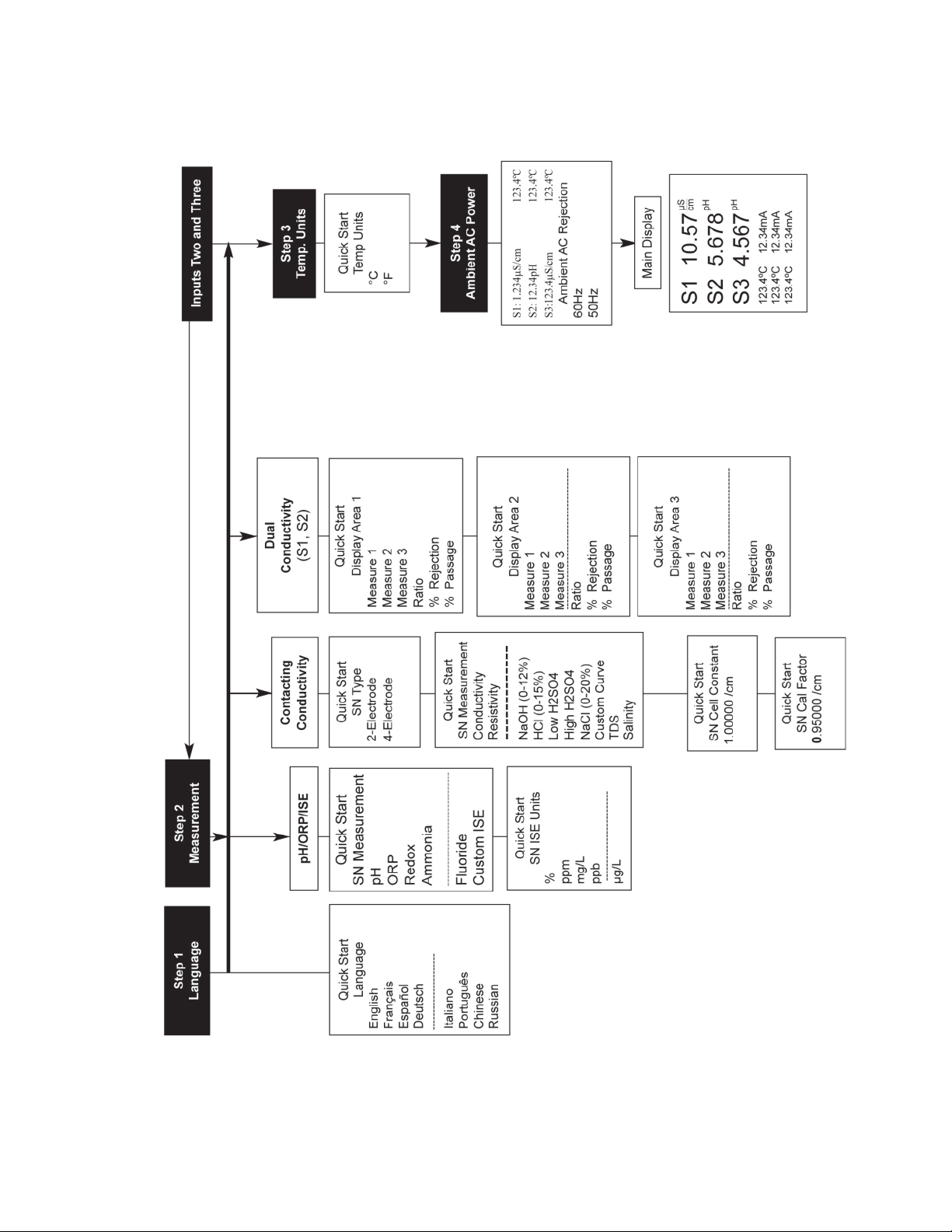
5. Complete the steps as shown in the Quick Start Guide flow diagram,
6. After the last step, the main display appears. The outputs are assigned to default values.
7. To change output, and temperature-related settings, go to the main menu and choose Program. Follow the
prompts. For a general guide to the Program menu, see the Quick Reference Guide, Figure B.
8. To return the analyzer to the default settings, choose Reset Analyzer under the Program menu.
Figure A .
Quick Start Guide iii
Page 6
Quick Start Guide
igure A. Quick Start Guide
F
Quick Start Guideiv
Page 7
Quick Reference Guide
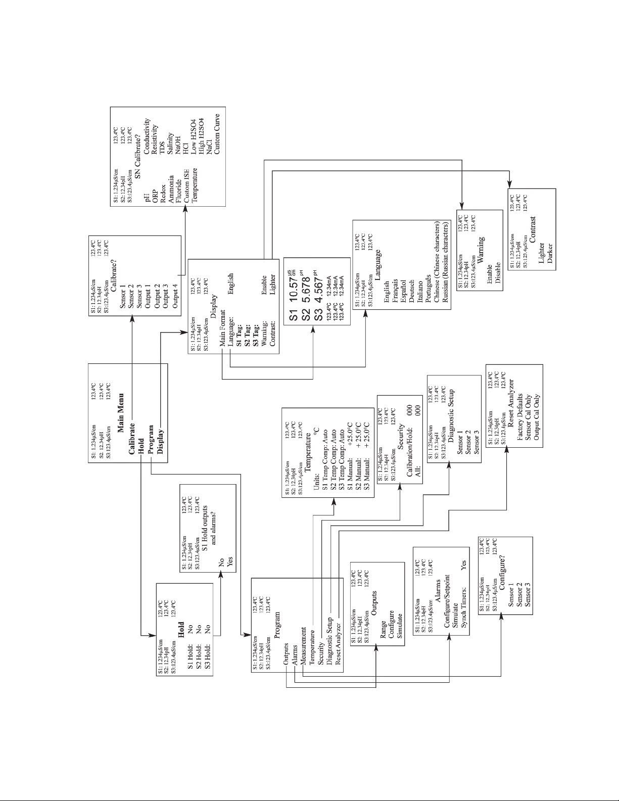
igure B. Model 1057 Menu Tree
F
Quick Reference Guide v
Page 8

About This Document
his manual contains instructions for installation and operation of the Model 1057 Three-Input Intelligent Analyzer. The
T
following list provides notes concerning all revisions of this document.
ev. Level Date Notes
R
A
B 10/09 Russian language added. UL Approval added.
C 01/10 CSA Class I, Div 2 Non-incendive harardous area approval added.
D 04/17 Updated Address and Emerson Logo. Also, updated CE declaration.
01/09 This is the initial release of the product manual. The manual has been reformatted
o reflect the Emerson documentation style and updated to reflect any changes
t
in the product offering.
Quick Start Guidevi
Page 9

Instruction Manual
LIQ-MAN-1057
Contents
Section 1: Description and Specifications
Section 2: Installation
Section 3: Wiring
Table of Contents
April 2017
Quick Start Guide ...................................................................................................................iii
Quick Reference Guide............................................................................................................v
About This Document............................................................................................................vi
Table of Contents...................................................................................................................vii
1.1 Features and Applications...........................................................................................1
1.2 Specifications - General ................................................................................................2
1.3 Contacting Conductivity (Codes -20, -30, -40).............................................................4
1.4 pH/ORP/ISE (Codes -22, -32, -42).................................................................................5
2.1 Unpacking and Inspection............................................................................................7
2.2 Installation....................................................................................................................7
3.1 General ...................................................................................................................... 11
3.2 Preparing Conduit Openings......................................................................................12
3.3 Preparing Sensor Cable ..............................................................................................12
3.4 Power, Output and Sensor Connections.....................................................................12
Section 4: Display and operation
4.1 User Interface.............................................................................................................17
4.2 Instrument Keypad.....................................................................................................17
4.3 Main Display...............................................................................................................18
4.4 Menu System..............................................................................................................19
Section 5: Programming the Analyzer – Basics
5.1 General.......................................................................................................................21
5.2 Changing the Startup Settings...................................................................................21
5.3 Choosing Temperature Units and Automatic/Manual
Temperature Compensation......................................................................................22
5.4 Configuring and Ranging The Current Outputs..........................................................22
5.5 Setting a Security Code..............................................................................................24
5.6 Security Access...........................................................................................................24
5.7 Using Hold..................................................................................................................25
5.8 Resetting the Factory Default Settings.......................................................................25
5.9 Programming Alarm Relays........................................................................................26
Table of Contents vii
Page 10

Table of Contents
April 2017
Section 6: Programming Measurements
Section 7: Calibration
Section 8: Return of Material
EC Declarations of Conformity............................................................................................................55
Instruction Manual
LIQ-MAN-1057
6.1 Programming Measurements - Introduction...........................................................31
.2pH Measurement Programming ................................................................................31
6
6.3 ORP Measurement Programming..............................................................................33
6.4 Contacting Conductivity............................................................................................34
7.1 Unpacking and Inspection..........................................................................................41
7.2 pH Calibration ............................................................................................................41
7.3 ORP Calibration..........................................................................................................44
7.4 Contacting Conductivity Calibration..........................................................................45
7.5 Calibrating Temperature ............................................................................................48
8.1 General ...................................................................................................................... 53
8.2 Warranty Repair .........................................................................................................53
8.3 Non-Warranty Repair .................................................................................................53
Table of Contentsviii
Page 11

nstruction Manual
I
LIQ-MAN-1057
ection 1: Description and Specification
S
Section 1: Description and Specification
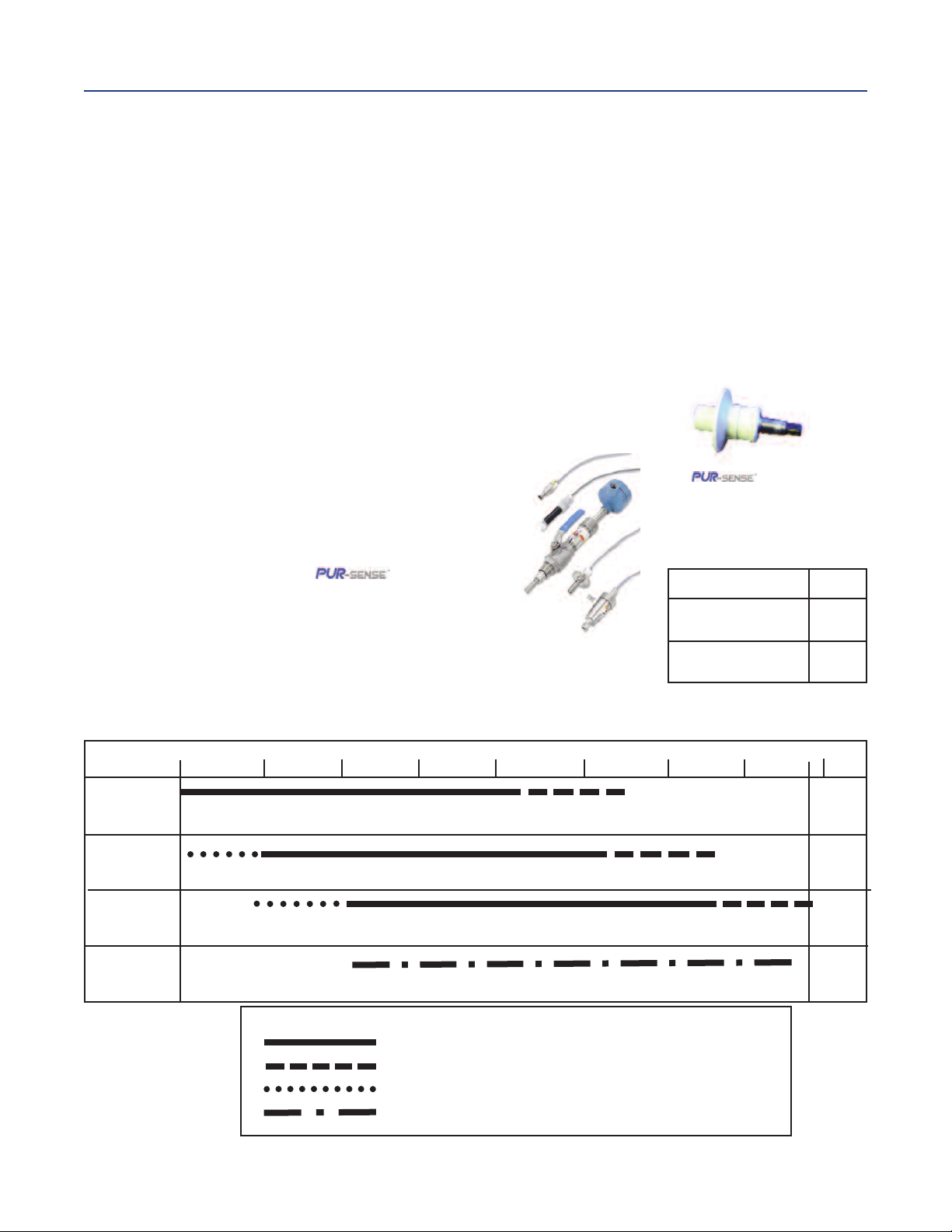
• Multi-parameter instrument – up to three inputs. Choose pH/ORP/ISE or contacting
onductivity/resistivity in any combination.
c
• Large display – large easy-to-read process measurements.
• Easy to install – modular boards, removable connectors, easy to wire power, sensors, an
outputs.
• Intuitive menu screens with advanced diagnostics and help screens.
• SMART - Enabled - compatible with SMART pH sensors.
• Eight menu languages.
• Four analog outputs.
• UL and CSA approved.
1.1 Features and Applications
April 2017
The Model 1057 analyzer offers three sensor inputs and four current outputs thus reducing the cost
per loop and saving panel space. The pH signal input board supports pH, ORP, and Ion-Selective
Electrode measurements. The conductivity signal input board supports contacting conductivity,
resistivity, total dissolved solids, salinity and percent concentration curves for special applications.
The modular design allows signal input boards to be field replaced making configuration changes
easy. Conveniently, live process values are always displayed during programming and calibration
routines. Standard features include isolated inputs, eight embedded local languages, four 4-20mA
current outputs, four alarm relays and removable connectors for power and current outputs.
Quick Start Programming: Exclusive quick start screens appear the first time the Model 1057 is
powered. The instrument auto-recognizes each measurement board and prompts the user to
configure each sensor loop in a few quick steps for immediate deployment.
Menus: Menu screens for calibrating and programming are simple and intuitive. Plain language
prompts and help screens guide the user through these procedures.
4-Electrode Conductivity: For applications requiring wide range conductivity measurements, use
Rosemount Model 410VP 4-electrode sensor. It is not affected by fouling and is
supported by the same contacting conductivity signal board as traditional 2-electrode sensors.
Three Sensor Inputs: The Model 1057 accepts one, two or three isolated inputs. Inputs are isolated
from other signal sources and earth ground.
Four Current Outputs: Four 0/4-20 mA current outputs are electrically isolated. Outputs are fully
scalable and can be programmed to linear or logrithmic modes. Output dampening can be enabled
with time constants from 0 to 999 seconds.
Enclosure: The instrument fits standard ½ DIN panel cutouts. The versatile enclosure design
supports panel-mount, pipe-mount, and surface/wall-mount installations.
Smart pH Sensors: Avoid buffer calibrations in the field. Use Rosemount SMART pH sensors to
automatically calibrate the measurement loop when connected to Model 1057. Choose from a
complete range of SMART pH sensors suited to most applications.
Section 1: Description and Specification 1
Page 12

ection 1: Description and Specification
S
April 2017
ecurity Access Codes: Two levels of security access are available. Program one access code for
S
routine calibration and hold of current outputs; program another access code for all menus and
functions.
Diagnostics: The analyzer continuously monitors itself and the sensor(s) for problematic conditions.
The display flashes fault and/or warning when these conditions occur.
Diagnostics
Faults
Warnings
Sensor 1
Sensor 2
Sensor 3
Out 1: 12.05 mA
Out 2: 12.05 mA
Out 3: 12.05 mA
Out 4: 12.05 mA
1057PPC03AN
Instr SW VER: 3.12
AC Freq. Used: 60Hz
nstruction Manual
I
Information about each condition is quickly accessible
by pressing DIAG on the keypad. User help screens are
displayed for most fault and warning conditions to assist
in troubleshooting.
LIQ-MAN-1057
Display: The high-contrast LCD provides live measurement readouts in large digits and shows up to
six additional process variables or diagnostic parameters. The display is back-lit and the format can
be customized to meet user requirements.
Local Languages: Rosemount extends its worldwide reach by offering eight local languages
– English, French, German, Italian, Spanish, Portuguese, Chinese and Russian. Every unit includes user
programming menus; calibration routines; faults and warnings; and user help screens in all eight lan
guages. The displayed language can be easily set and changed using the menus.
1.2 Specifications - General
Enclosure: Polycarbonate. Type: CSA 4X (IP65).
Dimensions: Overall 155 x 155 x 131mm (6.10 x 6.10 x 5.15 in.). Cutout: 1/2 DIN 139mm x 139mm
(5.45 x 5.45 in.)
Minimum depth for panel mount insatllations 101.6 mm (4.0 in).
Conduit Openings: Accepts 1/2” or PG13.5 conduit fitings
Display: Monochromatic graphic liquid crystal display. 128 x 96 pixel display resolution.
Backlit. Active
display area: 58 x 78mm (2.3 x 3.0 in.).
Ambient Temperature and Humidity: 0 to 55 °C (32 to 131 °F). RH 5 to 95% (non-condensing)
Storage Temperature Effect: -20 to 60 °C (-4 to 140 °F)
Power: Code 02: 20 to 30 Vdc. 15 W.
Code 03: 84 to 265 Vac, 47.5 to 65.0 Hz, switching. 15 W.
Equipment protected by double insulation
Section 1: Description and Specification2
Page 13
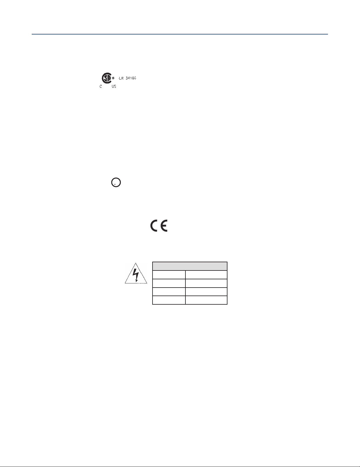
U
L
US
C
LI
STED
nstruction Manual
I
LIQ-MAN-1057
ection 1: Description and Specification
S
April 2017
azardous Location Approvals:
H
Options for CSA: 02, 03, 20, 21, 22, 24, 25, 26, 30, 31, 32, 34, 35, 36, 38, 40, 41, 42, 44, 45,
6, 48, UL
4
Class I, Division 2, Groups A, B, C, & D
Class Il, Division 2, Groups E, F, & G
Class Ill
T4 Tamb= 55 °C (applies to all classes)
Type 4X, IP66
Non-Incendive Field Wiring (NIFW) may be used when installed per drawing 1400680.
The ‘C’ and ‘US’ indicators adjacent to the CSA Mark signify that the product has been
evaluated to the applicable CSA and ANSI/UL Standards, for use in Canada and the U.S.
respectively.
Evaluated to CSA Standard 22.2 No. 0-10, 0.4-04, 25-1996, 94- M1991, 142-M1987, 213M1987, 60529-2005/2015. ANSI/IEC 60529-2004/2011. ANSI/ISA 12.12.01:2007. UL No.
50, 11th Ed., 508,17th Ed.
Ordinary Locations (only with UL ordering option):
Pollution Degree 2: Normally only non-conductive pollution occurs. Occasionally, however,
a temporary conductivity caused by condensation must be expected.
Altitude: for use up to 2000 meter (6562 ft.)
RFI/EMI: EN 61326-1
LVD: EN 61010-1
Alarm Relays: Four alarm relays for process measurement(s) or temperature. Any relay can be
configured as a fault alarm instead of a process alarm. Each relay can be configured
independently and each can be programmed with interval timer settings.
Maximum Relay Current
Resistive
28 Vdc 5.0 A
115 Vac 5.0 A
230 Vac 5.0 A
Inputs: Up to three sensor inputs-electrically isolated.
Relays: Form C, SPDT, epoxy sealed
Inductive load: 1/8 HP motor (max.), 120/240 Vac
Inductive load: Four 4-20 mA or 0-20 mA isolated current outputs. Fully scalable. Max Load:
550 Ohms.
Current Output Accuracy: ±0.05 mA @25 °C
Terminal Connections Rating:
Power connector (3-leads): 24-12 AWG wire size. Signal board terminal blocks: 26-16 AWG
wire size. Current output connectors (4-leads): 24-16 AWG wire size. Alarm relay terminal
blocks: 24-12 AWG wire size
Weight/Shipping Weight: (rounded up to nearest lb or nearest 0.5 kg): 3 lbs/4 lbs
(1.5 kg/2.0 kg)
Section 1: Description and Specification 3
Page 14
ection 1: Description and Specification
S
April 2017
nstruction Manual
I
LIQ-MAN-1057
1.3 Contacting Conductivity (Codes -20, -30 and -40)
Measures conductivity in the range 0 to 600,000 µS/cm (600mS/cm). Measurement choices are
conductivity, resistivity, total dissolved solids, salinity, and % concentration. The % concentration
election includes the choice of five common solutions (0-12% NaOH,0-15% HCl, 0-20% NaCl, and 0-25%
s
or 96-99.7% H
temperature compensated. Three temperature compensation options are available: manual slope
(X%/°C), high purity water (dilute sodium chloride), and cation conductivity (dilute hydrochloric acid).
Temperature compensation can be disabled, allowing the analyzer to display raw conductivity. For
more information concerning the use and operation of the contacting conductivity sensors, refer to
the product data sheets.
Note: When contacting conductivity sensors are used for sensor 1 and sensor 2, Model 1057 can
derive an inferred pH value called pHCalc. pHCalc is calculated pH, not directly measured pH.
Note: Selected 4-electrode, high-range contacting conductivity sensors are compatible with
Model 1056.
Input filter: time constant 1 - 999 seconds, default 2 seconds
Response time: 3 seconds to 100% of final reading
Salinity: Uses Practical Salinity Scale
). The conductivity concentration algorithms for these solutions are fully
2SO4
Total Dissolved Solids: Calculated by
multiplying conductivity at 25 °C by 0.65
4-electrode sensors
family
Recommended Sensors For Conductivity
All Rosemount ENDURANCE
Model 400 series conductivity sensors
(Pt 1000 RTD) and Model 410 sensor.
ENDURANCETMseries of
conductivity sensors
Temperature Specifications:
Temperature range 0-200 °C
Temperature Accuracy,
Pt-1000, 0-50 °C
Temperature Accuracy,
Pt-1000, Temp. > 50 °C
± 0.1 °C
± 0.5 °C
Performance Specifications
Recommended Range – Contacting Conductivity
Cell 0.01µS/cm 0.1µS/cm 1.0µS/cm 10µS/cm 100µS/cm 1000µS/cm 10mS/cm 100mS/cm 1000mS/cm
Constant
0.01
0.1
1.0
0.01µS/cm to 200µS/cm
0.1µS/cm to 2000µS/cm
1 µS/cm to 20mS/cm
200µS/cm to 6000µS/cm
2000µS/cm to 60mS/cm
20mS/cm to 600mS/cm
4-electrode
2 µS/cm to 300mS/cm
Cell Constant Linearity
±0.6% of reading in recommended range
+2 to -10% of reading outside high recommended range
±5% of reading outside low recommended range
±4% of reading in recommended range
Section 1: Description and Specification4
Page 15

nstruction Manual
I
LIQ-MAN-1057
ection 1: Description and Specification
S
1.4 pH/ORP/ISE (Codes -22, -32, and -42)
For use with any standard pH or ORP sensor. Measurement choices are pH, ORP, Redox, ammonia,
fluoride or custom ISE. The automatic buffer recognition feature uses stored buffer values and their
emperature curves for the most common buffer standards available worldwide. The analyzer will
t
recognize the value of the buffer being measured and perform a self stabilization check on the sensor
before completing the calibration. Manual or automatic temperature compensation is menu
selectable. Change in pH due to process temperature can be compensated using a programmable
temperature coefficient. For more information concerning the use and operation of the pH or ORP
sensors, refer to the product data sheets.
Model 1057 can also derive an inferred pH value called pHCalc (calculated pH). pHCalc can be derived
and displayed when two contacting conductivity sensors are used as sensor 1 and sensor 2.
Performance Specifications - Analyzer (pH Input)
Measurement Range [pH]: 0 to 14 pH
Accuracy: ±0.01 pH
Diagnostics: Glass impedance, reference impedance
Temperature coefficient: ±0.002pH/ °C
Solution temperature correction: Pure water, dilute base and custom.
Buffer recognition: NIST, DIN 19266, JIS 8802, and BSI.
Input filter: Time constant 1 - 999 seconds, default 4 seconds.
Response time: 5 seconds to 100%
Sensor Compatibility: Model 1057 is also compatible with SMART pH sensors from Rosemount.
Choose from 14 SMART sensor models for a wide array of applications and process
conditions.
April 2017
Performance Specifications - Analyzer (ORP Input)
Measurement Range [ORP]: -1500 to +1500 mV
Accuracy: ± 1 mV
Temperature coefficient: ±0.12mV / °C
Input filter: Time constant 1 - 999 seconds,
default 4 seconds.
Response time: 5 seconds to 100% of final reading
Recommended Sensors For ORP: All standard
ORP sensors.
Temperature Specifications:
Temperature range 0-150 °C
Temperature Accuracy, Pt-100, 0-50 °C ± 0.5 °C
Temperature Accuracy, Temp. > 50 °C ± 1 °C
Fourteen SMART sensor models include PERpH-X,
TUpH and general purpose pH sensor families.
Section 1: Description and Specification 5
Page 16

Section 1: Description and Specification
April 2017
Instruction Manual
LIQ-MAN-1057
Section 1: Description and Specification6
Page 17

Instruction Manual
LIQ-MAN-1057
Section 2: Installation
2.1 Unpacking and Inspection
Inspect the shipping container. If it is damaged, contact the shipper immediately for instructions. Save
the box. If there is no apparent damage, unpack the container. Be sure all items shown on the packing
list are present. If items are missing, notify Rosemount immediately.
2.2 Installation
2.2.1 General Information
1. Although the analyzer is suitable for outdoor use, do not install it in direct sunlight or in areas
of extreme temperatures.
2. Install the analyzer in an area where vibration and electromagnetic and radio frequency
interference are minimized or absent.
3. Keep the analyzer and sensor wiring at least one foot from high voltage conductors. Be sure
there is easy access to the analyzer.
4. The analyzer is suitable for panel mounting (Figure 2-1) or Wall and pipe
mounting (Figure 2-2).
Section 2: Installation
April 2017
WARNING
RIS
K
OF
EL
Electric
al
an
o
th
e
r
applic
EC
TRIC
ins
t
allation
able national or
AL
S
HO
C
K
m
us
t
be
in
ac
loc
cordance
al codes
w
ith
the
National
.
Elec
tric
al
Code
(A
NSI
/
N
F
P
A
-
70)
and/
or
Section 2: Installation 7
Page 18
Section 2: Installation
April 2017
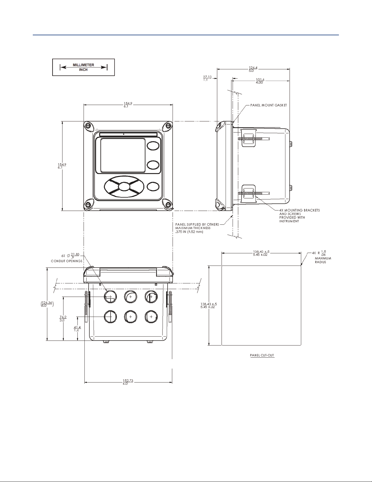
Figure 2-1 Panel Mounting Dimensions
Instruction Manual
LIQ-MAN-1057
Front View
Bottom View
Side View
The front panel is hinged at the bottom. The panel swings down for easy access to the wiring locations. Panel
mounting seal integrity (4/4X) for outdoor applications is the responsibility of the end user.
Section 2: Installation8
Page 19
nstruction Manual
I
LIQ-MAN-1057
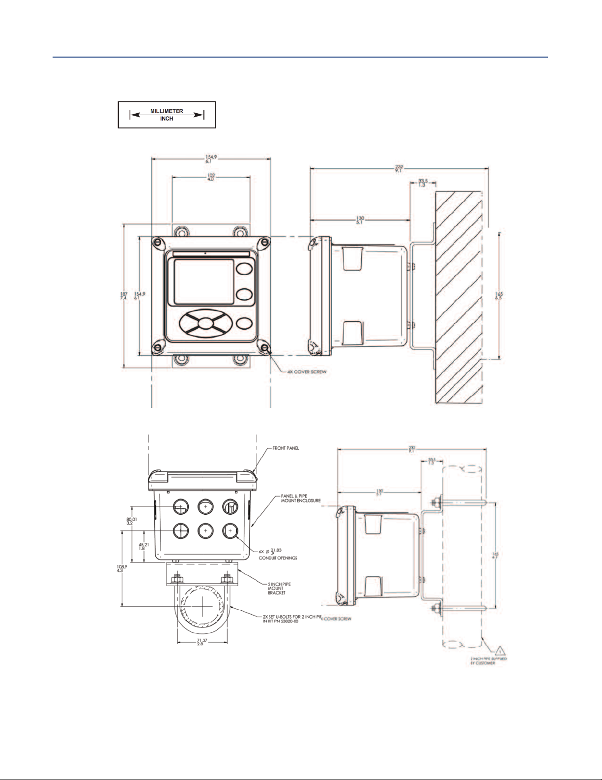
Figure 2-2 Pipe and Wall Mounting Dimensions
Wall / Surface Mount
ection 2: Installation
S
April 2017
Front View
Bottom View
Side View
Pipe Mount
Side View
The front panel is hinged at the bottom. The panel swings down for easy access to the wiring locations.
Section 2: Installation 9
Page 20
Section 2: Installation
OR
OR
OR
U4
R32
C
47
2
1
J
2
6
5
1
J4
4
R
11
U9
U18
U15
U16
U13
U5
C49
C
46
R77
R
73
U3
R
3
R1
1
J3
2
U1
C
8
U2
R9
R4
R10
Z
6
C16
R
23
R
15
U10
C6
R
6
+
C
19
+
C
20
+
C
28
C
24
+
C
21
+
+
C
55
R75
C41
R58
R
57
C
43
C
1
3
U6
R
12
C52
R49
C
37
C
42
R67
C
38
R
70
R
71
C54
R
72
C
56
R
74
R68
C23
C35
R50
C25
C26
R
28
R
22
C10
R30
Z
3
Z
4
R
35
C15
Z
5
C12
C14
R46
U
11
R41
C
27
C36
R
51
R47
J
1
C
30
R38
R
63
C
51
C
29
R64
R44
U
12
U8
R20
R
31
R
36
Y1
C
32
C
3
3
C34
R
8
R14
R21
R19
R16
R54
C
44
R
55
R
56
C45
R2
R69
U
7
C7
Q
3
R29
Z
1
C
5
R17
Z2
C
3
C
4
R5
R
61
R65
R66
C18
R
27
C1
R
7
R13
U20
C
48
C50
R62
R25
C
2
U
19
C22
R76
R
53
R45
C17
R60
R33
U
22
U
14
U
26
D
1
U
2
1
C39
T
B1
-5SHLD
RTD RTN
1
+5
SENSE
REF
GND
RTD IN
pH
SMART pH/ORP
ASSY 24312- REV
SHLD
R40
U
1
2
1
Z4
R
6
4
3
7
R
6
6
R
C3
C2
Z3
C4
5
6
R
U2
1
RTD RTN
CONTACTING
CONDUCTIVITY
ASSY 24355- REV
SHLDSHLD
RTD IN
SEN SEN
4CT4CT
SEN
SHLD
C
3
5
R40
R
5
2
C
3
8
C17
R
5
4
R
4
9
8
5
R
C44
C20
Q3
R44
R41
C
1
3
2
4
R
R13
R
5
5
C
12
5
3
R
9
2
C
C24
R
3
7
R
6
0
C
34
R36
R
7
5
R70
C
2
5
74C
C40
R20
U
1
4
C42
C62
C5
R45
C41
C54
C
1
C
39
C45
R9
R6
R68
C49
R67
1
5
C
C
5
5
C57
R63
R
3
R
12
R
1
C63
R25
R18
R30
Z
1
C65
C64
R7
3
5
C
Z9
C23
C30
+
C52
U
1
7
R
48
U16
1
R
74
R19
C18
U19
U2
R69
R72
U1
C21
R
3
1
R
4
6
R14
R
4
R5
1
3
C
C28
+
R57
U26
R53
7
2
C
+
0
5
C
+
C14
Z8
R
2
R
6
2
R61
R8
U
1
0
R11
R
76
R15
C16
R28
C56
R59
C
22
0
1
R
C26
+
U22
U
2
3
C
6
U11
TB1
2
3
C
C
3
6
C59
C7
C48
Z2
U24
Y1
R38
U
2
5
U4
U15
R
71
R47
C43
U
2
8
9
2
U
C58
C46
J1
U
6
U
5
TB2
1
6
C
8
C9
C10
C11
C15
C66
C
6
7
L1
Z5
U9
C60
+
U27
U20
6
Z
Z7
C37
1
6
C
POWER SUPPLY
ALARM
WIRING (VAC)
(OPTIONAL)
ANALOG OUTPUT
SENSOR 1
ANY CSA APPROVED DEVICE
OR SIMPLE APPARATUS
UNCLASSIFIED AREA
1057
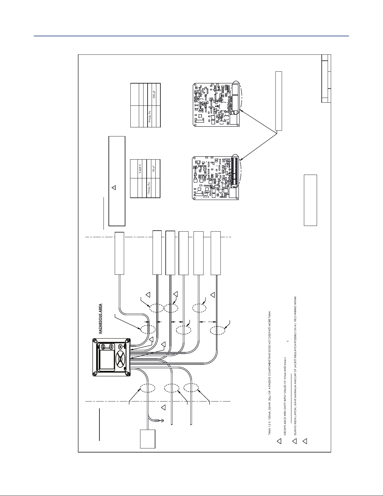
CLASS 1 DIVISION 2, GROUPS ABCD 0-50°C
CLASS II, III DIVISION 2 GROUPS EFG
6. SIMPLE APPARATUS IS DEFINED AS AN ELECTRICAL DEVICE THAT DOES NOT GENERATE MORE
1.3W. CONTACTING CONDUCTIVITY SENSORS AND pH, ORP, AMPEROMETRIC SENSORS WITHOUT
PREAMPS QUALIFY AS SIMPLE APPARATUS.
5
NON-INCENDIVE FIELD WIRING METHODS MAY BE USED FOR CONNECTING SENSORS TO THE 20/30 AND 22/32
OPTION BOARDS. SENSORS MUST BE CSA APPROVED AS NON-INCENDIVE FOR CLASS I, DIVISION 2,
Voc AND Isc LISTED IN TABLES 1A TO 1C
AND THE Ci AND Li OF THE SENSOR AND INTERCONNECTED WIRING MUST BE
Ca AND La LISTED IN TABLES
1A TO 1C
OR BE CLASSIFIED AS SIMPLE APPARATUS
.
4
INSTRUMENT ENCLOSURE. AFTER TERMINATION, WRAP N.I. FIELD WIRING WITHIN ENCLOSURE WITH MYLAR TAPE, TO
ENSURE ADEQUATE DOUBLE INSULATION REMAINS.
3
GROUND CONNECTION MAY BE MADE IN HAZARDOUS AREA.
2. SEAL REQUIRED AT EACH CONDUIT ENTRANCE, WHEN CONDUIT IS USED.
1. INSTALLATION MUST CONFORM TO THE CEC.
SENSOR 2 (OPTIONAL)
ANY CSA APPROVED DEVICE OR
SIMPLE APPARATUS
UNCLASSIFIED AREA
METAL CONDUIT
METAL CONDUIT
METAL CONDUIT
METAL CONDUIT
SENSOR CABLE
IS SHIELDED
5
METAL CONDUIT
3
4
4
SENSOR 1
ANY CSA APPROVED DEVICE OR
SIMPLE APPARATUS
WARNING
IF THE SENSOR TIP HAS EXPOSED ELECTRODES,
THEN IT MUST ONLY BE USED IN A NON-FLAMMABLE LIQUID PROCESS
TABLE 1A
ENTITY PARAMETERS FOR
OPTION 22/32 (pH / ORP / ISE SENSOR BOARD)
TABLE 1B
ENTITY PARAMETERS FOR OPTION 20/30
(CONTACTING CONDUCTIVITY SENSOR BOARD)
SENSOR 3 (OPTIONAL)
ANY CSA APPROVED DEVICE OR
SIMPLE APPARATUS
SENSOR 3 (OPTIONAL)
ANY CSA APPROVED DEVICE OR
SIMPLE APPARATUS
SENSOR 2 (OPTIONAL)
ANY CSA APPROVED DEVICE OR
SIMPLE APPARATUS
METAL CONDUIT
SENSOR CABLE
IS SHIELDED
5
5
SENSOR CABLE
IS SHIELDED
NON-INCENDIVE FIELD WIRING CONNECTIONS
FOR CLASS 1, DIVISION 2, GROUPS ABCD
OPTION 22/32 (pH/ORP SENSOR BOARD)
OPTION 20/30 (CONTACTING CONDUCTIVITY SENSOR BOARD)
OUTPUT
PARAMETERS
pH TB1
CONNECTOR
Voc, Vo
Isc, Io
115 mA
276.8 mW
Ca
La
6 mH
OUTPUT
PARAMETERS
CONDUCTIVITY
CONNECTORS
TB1, TB2
Voc, Vo
6.633 V
Isc, Io
30.45 mA
50.5 mW
Ca
La
85 mH
NOTES: UNLESS OTHERWISE SPECIFIED
SCALE: 1:1
WEIGHT:
SIZE
D
DWG NO
SHEET 1 OF 1
B
1400680
REV
THIS DOCUMENT IS CERTIFIED BY
CSA (REVISION A)
REVISIONS ARE NOT PERMITTED
WITHOUT CSA APPROVAL
April 2017
igure 2-3 Non Incendive Field Wiring Installation (CSA)
F
Instruction Manual
LIQ-MAN-1057
Section 2: Installation10
Page 21
nstruction Manual
I
LIQ-MAN-1057
Section 3: Wiring
3.1 General
The Model 1057 is easy to wire. It includes removable connectors and slide-out signal input boards.
3.1.1 Removable Connectors and Signal Input Boards
Model 1057 uses removable signal input boards and communication boards for ease of wiring
and installation. Each of the signal input boards can be partially or completely removed from the
enclosure for wiring. The Model 1057 has three slots for placement of up to three signal
input boards and one communication board.
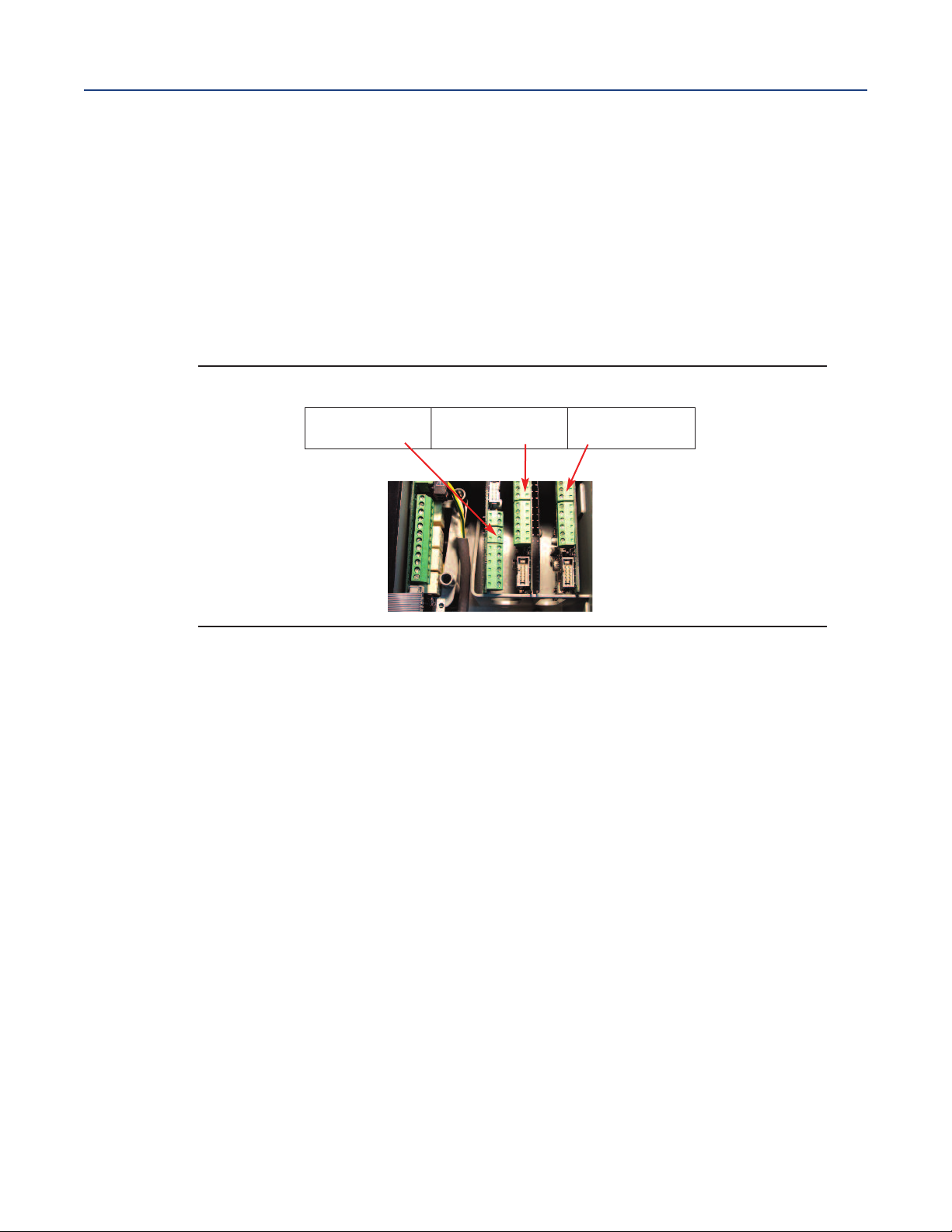
Figure 3-1 Model 1057 Signal Input Boards
ection 3: Wiring
S
April 2017
Slot 1 – Left
Signal board 3
Note: If the UL option code has been ordered, a plastic insulator shield surrounds the entire power
supply board (AC power supply only). The protective insulator shield does not appear in this photo.
3.1.2 Signal Input Boards
Slots 1, 2 and 3 are for signal input measurement boards. Wire the sensor leads to the
measurement board following the lead locations marked on the board. After wiring the sensor leads
to the signal board, carefully slide the wired board fully into the enclosure slot and take up the excess
sensor cable through the cable gland. Tighten the cable gland nut to secure the cable and ensure a
sealed enclosure.
Note: that signal input board 3 is inserted into slot 1. Board 3 is inverted in the slot to allow board
components to face to the right. Board 3 uses a long ribbon cable to connect to the main PCB. Boards
1 and 2 use a split ribbon cable to connect both signal boards to a common connector on the
main board.
Slot 2 – Center
Signal board 2
Slot 3 – Right
Signal board 1
3.1.3 Alarm Relays
Four alarm relays are supplied with the switching power supply (84 to 265 Vac, 03 order code) and the
24 Vdc power supply (20-30 Vdc, 02 order code). All relays can be used for process measurements
or temperature. Any relay can be configured as a fault alarm instead of a process alarm. Each
relay can be configured independently and each can be programmed as an interval timer, typically
used to activate pumps or control valves. As process alarms, alarm logic (high or low activation or
USP*) and deadband are user-programmable. Customer-defined failsafe operation is supported as a
programmable menu function to allow all relays to be energized or not-energized as a default
condition upon powering the analyzer. The USP alarm can be programmed to activate when the
conductivity is within a user-selectable percentage of the limit. USP alarming is available only when a
contacting conductivity measurement board is installed.
Section 3: Wiring 11
Page 22
Section 3: Wiring
April 2017
3.2 Preparing Conduit Openings
here are six conduit openings in all configurations of Model 1057. (Note that four plugs are provided
T
upon shipment.)
Note: Use watertight fittings and hubs that comply with your requirements. Connect the conduit
hub to the conduit before attaching the fitting to the analyzer.
3.3 Preparing Sensor Cable
The Model 1057 is intended for use with all Rosemount pH/ORP and contacting
conductivity sensors. Refer to the sensor installation instructions for details on preparing
sensor cables.
3.4 Power, Output and Sensor Connections
All field wiring must be rated for 75 °C or higher. Each instrument includes a printed label inside the
enclosure stating this wiring requirement.
3.4.1 Power Wiring
Two Power Supplies are offered for Model 1057:
a. 24 Vdc (20 – 30V) Power Supply (-02 ordering code)
b. 84 – 265 Vac Switching Power Supply (-03 ordering code)
AC mains (115 or 230V) leads and 24 Vdc leads are wired to the Power Supply board which is mounted
vertically on the left side of the main enclosure cavity. Each lead location is clearly marked on the
Power Supply board. Wire the power leads to the Power Supply board using the lead markings on
the board.
Instruction Manual
LIQ-MAN-1057
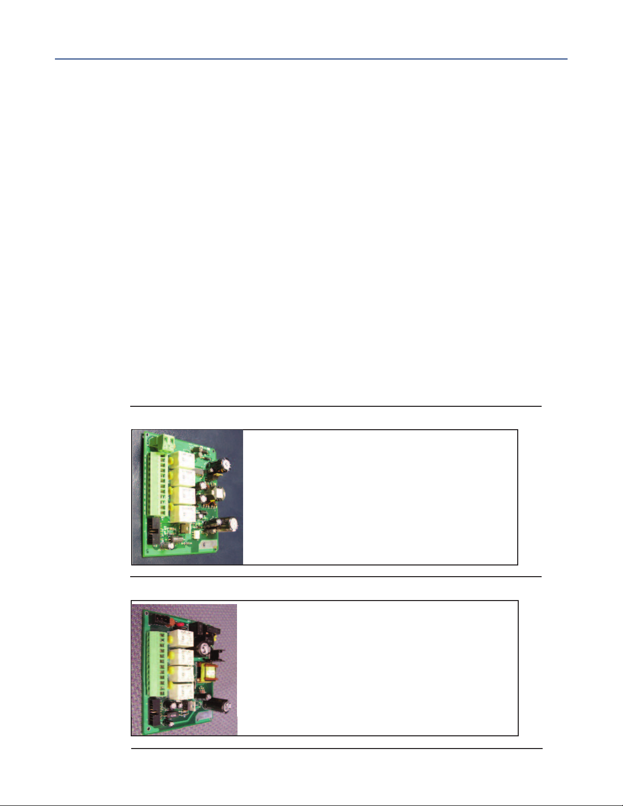
Figure 3-2 24 Vdc Power Supply (-02 ordering code)
This power supply automatically detects DC
power and accepts 20 Vdc to 30 Vdc inputs.
Four programmable alarm relays are included.
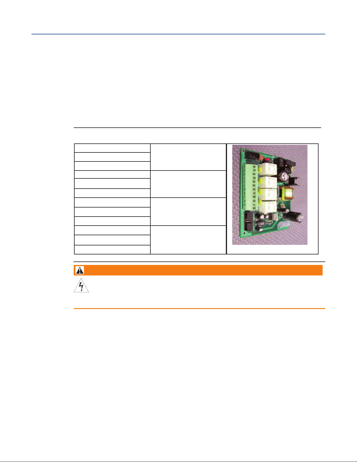
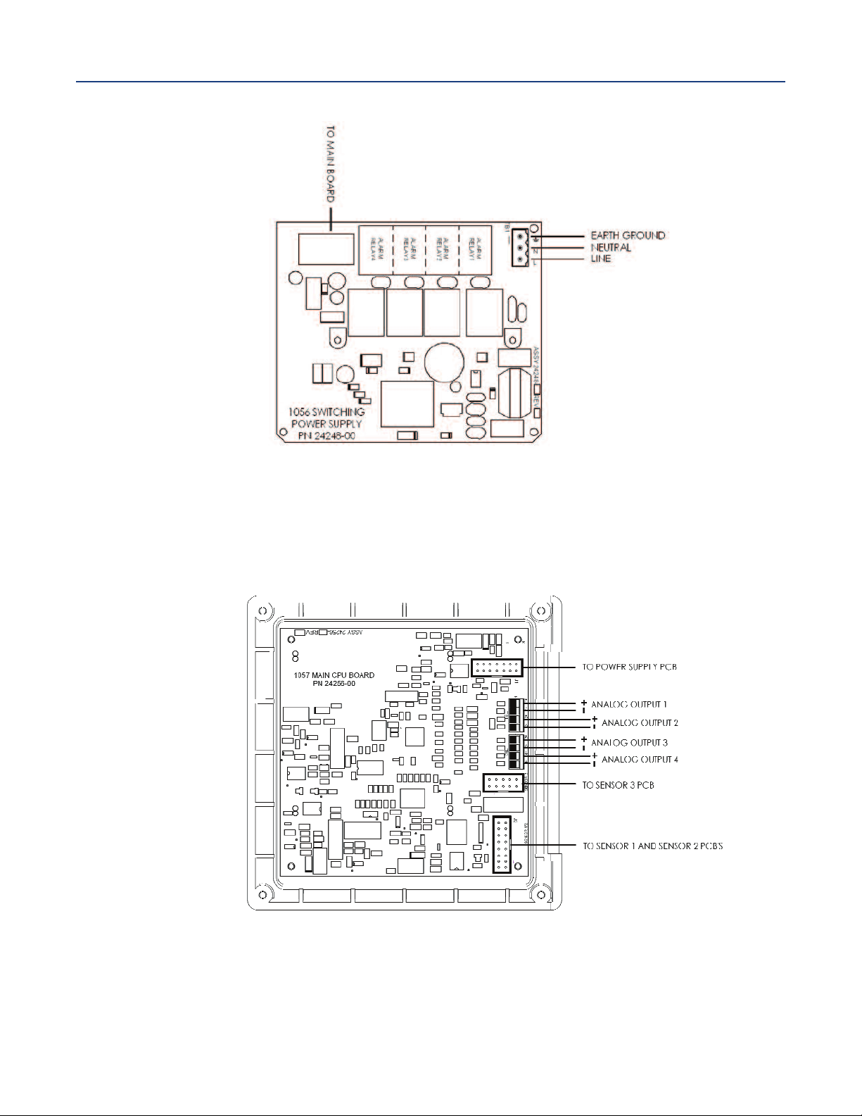
Figure 3-3 Switching AC Power Supply (-03 ordering code)
This power supply automatically detects AC line
conditions and switches to the proper line voltage and line frequency.
Four programmable alarm relays are included.
12
Section 3: Wiring
Page 23
Instruction Manual
LIQ-MAN-1057
3.4.2 Current Output Wiring
All instruments are shipped with four 4-20 mA current outputs. Wiring locations for the outputs are
on the main board which is mounted on the hinged door of the instrument. Wire the output leads to
he correct position on the Main board connectors using the lead markings (+/positive, -/negative)on the
t
board. Male mating connectors are provided with each unit. Use a 3/32” wide standard blade
screwdriver.
3.4.3 Alarm Relay Wiring
Four alarm relays are supplied with the switching power supply (84 to 265 Vac, -03 order code) and the
24 Vdc power supply (20-30 Vdc, -02 order code). Wire the relay leads on each of the independent
relays to the correct position on the power supply board using the printed lead markings
(NO/Normally Open, NC/Normally Closed, or Com/Common) on the board.
Figure 3-4 24 Vdc Power Supply (-02 ordering code)
NO1
COM1
NC1
NO2
COM2
NC2
NO3
COM3
NC3
NO4
COM4
NC4
Section 3: Wiring
April 2017
RELAY 1
RELAY 2
RELAY 3
RELAY 4
WARNING
RIS
K
OF EL
E
C
TRIC
AL
S
HO
C
K
Electric
al ins
tallation m
o
the
r
applic
able national or
us
t be in ac
loc
cordance w
al codes
ith the National Electric
.
al Code (A
NSI
/
N
F
P
A
-
70
) and/
or an
3.4.4 Sensor Wiring to Signal Boards
Wire the correct sensor leads to the measurement board using the lead locations marked directly on
the board. After wiring the sensor leads to the signal board, carefully slide the wired board fully into
the enclosure slot and take up the excess sensor cable through the cable gland.
For best EMI/RFI protection use shielded output signal cable enclosed in an earth-grounded metal
conduit. Connect the shield to earth ground. AC wiring should be 14 gauge or greater. Provide a
switch or breaker to disconnect the analyzer from the main power supply. Install the switch or break
er near the analyzer and label it as the disconnecting device for the analyzer.
Keep sensor and output signal wiring separate from power wiring. Do not run sensor and power wiring
in the same conduit or close together in a cable tray.
Section 3: Wiring 13
Page 24
Section 3: Wiring
April 2017
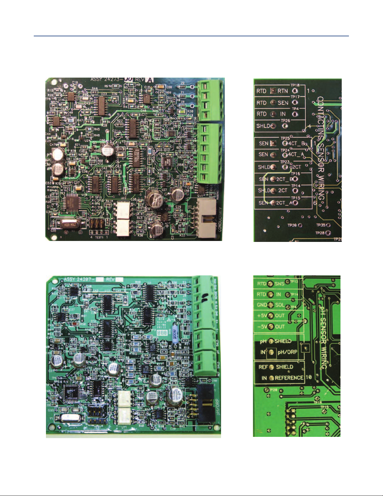
3.4.5 Signal Board Wiring
Figure 3-5 Contacting Conductivity Signal Board and Sensor Cable Leads
Instruction Manual
LIQ-MAN-1057
Figure 3-6 pH/ORP/ISE Signal Board and Sensor Cable Leads
Section 3: Wiring14
Page 25
nstruction Manual
I
LIQ-MAN-1057
Figure 3-7 Power Wiring for Model 1057 84-265 Vac Power Supply (-03 ordering code)
ection 3: Wiring
S
April 2017
Figure 3-8 Output Wiring for Model 1057 Main PCB
Section 1: Description and Specification 15
Page 26

Section 3: Wiring
April 2017
Figure 3-9 Power Wiring for Model 1057 24 Vdc Power Supply (-02 ordering code)
Instruction Manual
LIQ-MAN-1057
Section 3: Wiring16
Page 27

nstruction Manual
I
LIQ-MAN-1057
Section 4: Display and Operation
4.1 User Interface
The Model 1057 has a large display which shows three live
measurement readouts in large digits and up to six additional
process variables or diagnostic parameters concurrently. The
display is back-lit and the format can be customized to meet
user requirements. The intuitive menu system allows access
to Calibration, Hold (of current outputs), Programming, and
Display functions by pressing the MENU button. In addition, a
dedicated DIAGNOSTIC button is available to provide
access to useful operational information on installed sensor(s)
and any problematic conditions that might occur. The display
flashes Fault and/or Warning when these conditions occur.
Help screens are displayed for most fault and warning
conditions to guide the user in troubleshooting.During
calibration and programming, key presses cause different dis
plays to appear. The displays are self-explanatory and guide the
user step-by-step through the procedure.
ection 4: Display and Operation
S
April 2017
4.2 Instrument Keypad
There are four function keys and four selection keys on the instrument keypad.
Function Keys
The MENU key is used to access menus for programming and calibrating the instrument. Four toplevel menu items appear when pressing the MENU key:
• Calibrate – Calibrate attached sensors and analog
outputs.
• Hold – Suspend current outputs.
• Program– Program outputs, measurement,
temperature, security and reset.
• Display– Program display format, language, warnings,
and contrast.
Pressing MENUalways causes the main menu screen to appear. Pressing MENU followed by EXITcauses the
main display to appear.
Pressing the DIAGkey displays active Faults and Warnings, and provides detailed instrument information and
sensor diagnostics including: faults, warnings, sensor 1, 2 and 3 information, current outputs live values,
model configuration string e.g. 1057PPC03AN, Instrument Software version, and AC frequency.
Pressing ENTERon Sensor 1 or Sensor 2 provides useful diagnostics and information (as applicable):
measurement, sensor type, raw signal value, cell constant, zero offset and temperature. Offset, selected
measurement range, cable resistance, temperature sensor resistance, signal board software version.
The ENTERkey - Pressing ENTERstores numbers and settings and moves the display to the next screen.
The EXITkey - Pressing EXIT returns to the previous screen without storing changes.
Section 4: Display and Operation 17
Page 28

Section 4: Display and Operation
April 2017
Selection Keys
Surrounding the ENTER key, four selection keys – up, down, right and left, move the cursor to all areas of the
creen while using the menus.
s
Selection keys are used to:
1. Select items on the menu screens
2. Scroll up and down the menu lists.
3. Enter or edit numeric values.
4. Move the cursor to the right or left
5. Select measurement units during operations
4.3 Main Display
The Model 1057 displays one, two or three primary measurement values, up to six secondary
measurement values, a fault and warning banner, alarm relay flags.
4.3.1 Process Measurements
Three process variables are displayed if three signal boards are installed. One process variable and
process temperature is displayed if one signal board is installed with one sensor. The upper display
area shows the Sensor 1 process reading. The center display area shows the Sensor 2 process read
ing. For dual conductivity, the display areas can be assigned to different process variables as follows:
4.3.2 Secondary Values
Up to six secondary values are shown in six display quadrants at the bottom of the screen. All four
secondary value positions can be programmed by the user to any display parameter available.
Possible secondary values include:
Process variables for display - examples
Measure 1
Measure 2
Measure 3
% Reject
% Pass
Ratio
Blank
pH Calc
Instruction Manual
Displayable Secondary Values
Slope 1, 2, 3 Output 1 mA
Ref Off 1, 2, 3 Output 2 mA
Gl Imp 1, 2, 3 Output 3 mA
Ref Imp 1, 2, 3
Raw 1, 2, 3
mV Input 1, 2, 3 Output 2 %
Temp 1, 2, 3 Output 3 %
Man Temp 1, 2, 3 Output 4 %
Measure 1, 2, 3 Blank
Output 4 mA
Output 1 %
LIQ-MAN-1057
4.3.3 Fault and Warning Banner
If the analyzer detects a problem with itself or the sensor the word Faultor Warning will appear at the
bottom of the display. A fault requires immediate attention. A warning indicates a problematic
condition or an impending failure. For troubleshooting assitance, press Diag.
4.3.4 Formatting the Main Display
The main display screen can be programmed to show primary process variables, secondary process
variables and diagnostics.
Section 4: Display and Operation18
Page 29

nstruction Manual
I
LIQ-MAN-1057
4.3.4 Formatting the Main Display
he main display screen can be programmed to show primary process variables, secondary process
T
variables and diagnostics.
1. Press MENU.
2. Scroll down to Display. Press ENTER.
3. Main Format is highlighted. Press ENTER.
4. The Sensor 1 process value is highlighted in reverse video. Press the selection keys to
navigate down to the screen sections that you wish to program. Press ENTER.
5. Choose the desired display parameter or diagnostic for each of the four display sections in the
lower screen.
6. Continue to navigate and program all desired screen sections. Press MENU and EXIT. The
screen returns to the main display.
For single sensor configurations, the default display shows the live process measurement in the upper
display area and temperature in the center display area. The user can select to disable the display of
temperature in the center display area using the Main Format function. See
through programming the main display to select process parameters and diagnostics of your choice.
For dual sensor configurations, the default display shows Sensor 1 live process measurement in the
display area one and Sensor 2 live process measurement temperature in the display area two.
See Figure 4-1 to guide you through programming the main display to select process parameters and
diagnostics of your choice.
ection 4: Display and Operation
S
April 2017
Figure 4-1 to guide you
4.4 Menu System
Model 1057 uses a scroll and select menu system. Pressing the
MENU key at any time opens the top-level menu including
Calibrate, Hold, Program and Display functions.
To find a menu item, scroll with the up and down keys until the
item is highlighted. Continue to scroll and select menu items
until the desired function is chosen. To select the item, press
ENTER. To return to a previous menu level or to enable the main
live display, press the EXIT key repeatedly. To return
immediately to the main display from any menu level, simply
press MENU then EXIT.
The selection keys have the following functions:
•
• The Down key (below ENTER) decrements numerical values, moves the decimal place one place to
• The Left key (left of ENTER) moves the cursor to the left.
• The Right key (right of ENTER) moves the cursor to the right.
To access desired menu functions, use the Quick Reference Figure B. During all menu displays (except
main display format and Quick Start), the live process measurements and secondary measurement values
are displayed in the top two lines of the upper display area. This conveniently allows display of the live values
during important calibration and programming operations.
The Upkey (above ENTER) increments numerical values, moves the decimal place one place
to the right, or selects units of measurement.
the left, or selects units of measurement
Menu screens will time out after two minutes and return to the main live display.
Section 4: Display and Operation 19
Page 30

ection 4: Display and Operation
S
April 2017
Figure 4-1 Configuring the Main Display
nstruction Manual
I
LIQ-MAN-1057
Section 4: Display and Operation20
Page 31

nstruction Manual
I
LIQ-MAN-1057
ection 5: Programming the Analyzer - Basics
S
Section 5: Programming the Analyzer - Basics
5.1 General
This section describes the following programming functions:
• Changing the measurement type, measurement units and temperature units.
• Choose temperature units and manual or automatic temperature compensation mode
• Configure and assign values to the current outputs
• Set a security code for two levels of security access
• Accessing menu functions using a security code
• Enabling and disabling Hold mode for current outputs
• Choosing the frequency of the AC power (needed for optimum noise rejection)
• Resetting all factory defaults, calibration data only, or current output settings only
April 2017
5.2 Changing the Startup Settings
5.2.1 Purpose
To change the measurement type, measurement units, or temperature units that were initially
entered in Quick Start, choose the Reset Analyzer function (Section 5.8) or access the Program menus
for sensor 1, 2 or 3 (Section 6). The following choices for specific measurement type, measurement
units are available for each sensor measurement board.
Table 5-1 Measurments and measurement units
Signal board Available measurements Measurements units:
pH/ORP (-22, -32, -42)
Contacting conductivity
(-20, -30, -40)
Temperature (all) Temperature °C, °F
5.2.2 Procedure
Follow the Reset Analyzer procedure (Section 5.8) to reconfigure the analyzer to display new
measurements or measurement units. To change the specific measurement or measurement units for
each signal board type, refer to the Program menu for the appropriate measurement (Section 6).
pH, ORP, Redox, Ammonia, Fluoride,
Custom ISE
Conductivity, Resistivity, TDS, Salinity,
NaOH (0-12%), HCl (0-15%), Low H2SO4,
High H2SO4, NaCl (0-20%), Custom Curve
pH, mV (ORP)
%, ppm, mg/L, ppb, µg/L, (ISE)
µS/cm, mS/cm, S/cm
% (concentration)
Section 5: Programming the Analyzer - Basics 21
Page 32
ection 5: Programming the Analyzer - Basics
S
April 2017
nstruction Manual
I
LIQ-MAN-1057
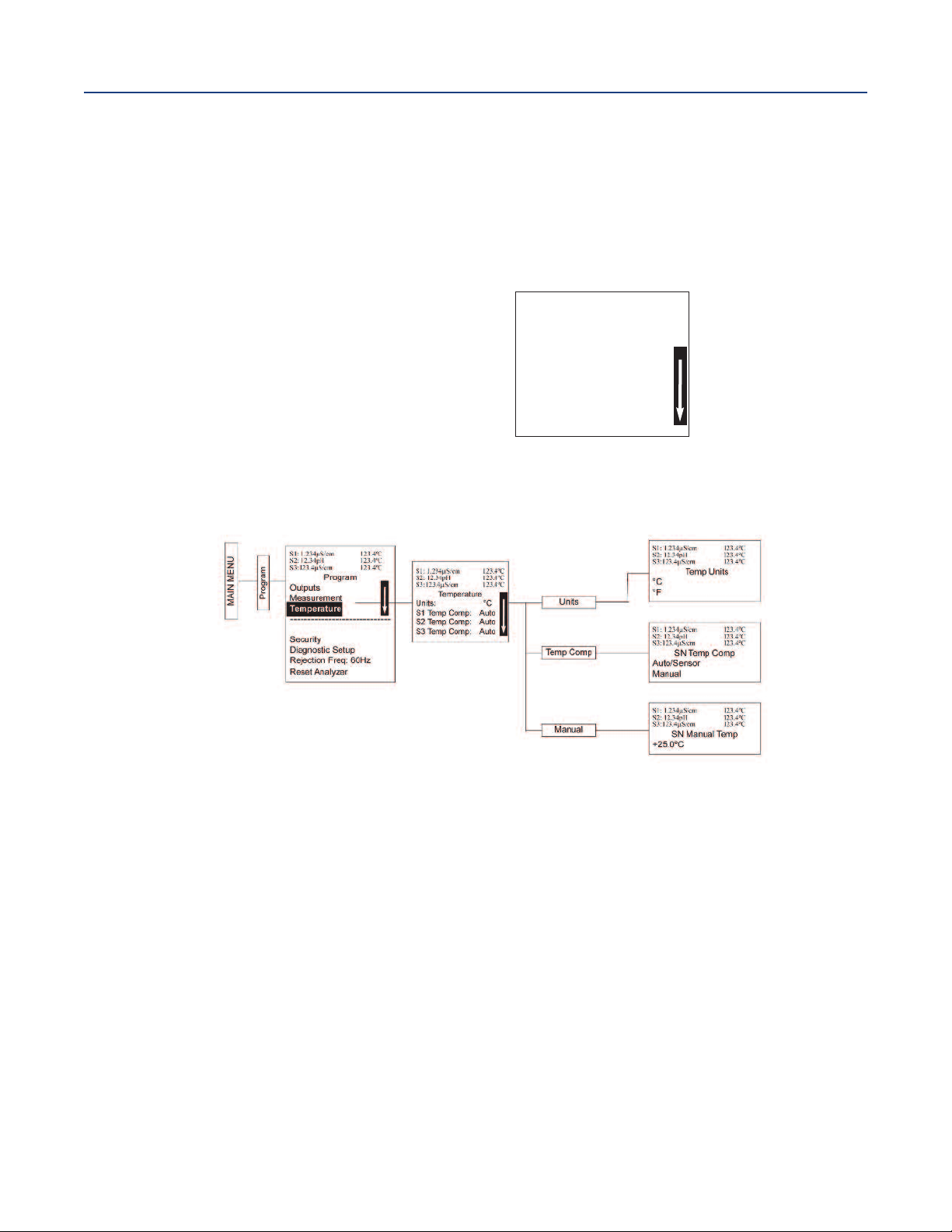
5.3 Choosing Temperature Units and Automatic/Manual
Temperature Compensation
5.3.1 Purpose
Most liquid analytical measurements (except ORP) require temperature compensation.
The Model 1057 performs temperature compensation automatically by applying internal temperature
correction algorithms. Temperature correction can also be turned off. If temperature correction is
off, the Model 1057 uses the temperature entered by the user in all temperature correction
calculations.
S1: 1.234µS/cm 123.4°C
S2: 12.34pH 123.4°C
S3:123.4µS/cm 123.4°C
Temperature
Units: °C
S1 Temp Comp: Auto
S2 Temp Comp: Auto
S3 Temp Comp: Auto
5.3.2 Procedure
Follow the menu screens in Figure 5-1 to select automatic or manual temp compensation, set the
manual reference temperature, and to program temperature units as °C or °F.
Figure 5-1 Choosing Temperature Units and Manual Auto Temp Compensation
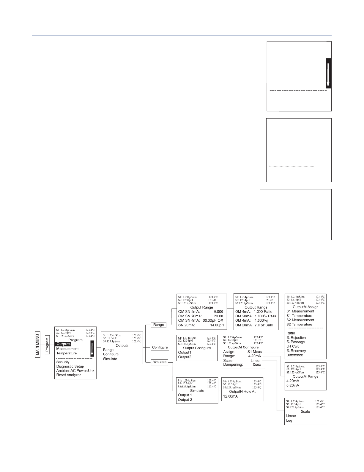
5.4 Configuring and Ranging The Current Outputs
5.4.1 Purpose
The Model 1057 accepts inputs from three sensors and has four analog current outputs. Ranging the
outputs means assigning values to the low (0 or 4 mA) and high (20 mA) outputs. This section
provides a guide for configuring and ranging the outputs. Always configure the outputs first.
5.4.2 Definitions
1. Current ouputs - The analyzer provides a continuous output current (4-20 mA or 0-20 mA)
directly proportional to the process variable or temperature. The low and high current outputs can be
set to any value.
2. Assigning outputs - Assign a measurement to outputs 1, 2, 3, or 4.
3. Dampen - Output dampening smooths out noisy readings. It also increases the response time of
the output. Output dampening does not affect the response time of the display.
4. Mode - The current output can be made directly proportional to the displayed value (linear mode)
or directly proportional to the common logarithm of the displayed value (log mode).
Section 5: Programming the Analyzer - Basics22
Page 33
nstruction Manual
I
LIQ-MAN-1057
5.4.3 Procedure - Configure Outputs
Under the Program/Outputs menu, the adjacent screen appears to
allow configuration of the outputs. Follow the menu screens in Figure 5-2 to
configure the outputs.
ection 5: Programming the Analyzer - Basics
S
April 2017
S
1
:
1
.
2
3
4
µ
S
/
c
m
1
2
3
.
4
°
S
2
S
3
Ass
Ran
S
c
D
am
F
au
F
a
:
1
2
.
3
4
p
H
:
1
2
3
.
4
µ
S
O
u
tpu
i
gn
:
ge
:
al
e:
pe
n
l
t
M
ode:
u
l
t
V
al
u
/
c
m
t
M
C
onfi
S
1
M
ea
4
-
2
0
mA
L
i
n
ear
i
n
g
:
0
Fi
x
ed
e:
2
1
.0
0
s
sec
mA
1
gu
C
2
3
.
4
°
C
1
2
3
.
4
°
C
r
e
5.4.4 Procedure - Assigning Measurements the Low and
High Current Outputs
The adjacent screen appears when entering the Assign function under
Program/Output/Configure. These screens allow you to assign a
measurement, process value, or temperature input to each output.
Follow the menu screens in Figure 5-2 to assign measurements to
the outputs.
5.4.5 Procedure - Ranging the Current Outputs
The adjacent screen appears under Program/Output/Range.
Enter a value for 4mA and 20mA (or 0 mA and 20 mA) for each output.
Follow the menu screens in Figure 5-2 to assign values to the outputs.
Figure 5-2 Configuring and Ranging the Current Outputs
S1: 1.234µS/cm 123.4°C
S2: 12.34pH 123.4°C
3:123.4µS/cm 123.4°C
S
OutputM Assign
S1 Measurement
S1 Temperature
S2 Measurement
S2 Temperature
S3 Measurement
S3 Temperature
S1: 1.234µS/cm 123.4°C
S2: 12.34pH 123.4°C
3:123.4µS/cm 123.4°C
S
Output Range
OM SN 4mA: 0.000µS/cm
OM SN 20mA: 20.00µS/cm
OM SN 4mA: 00.00pH
OM SN 20mA: 14.00pH
Section 5: Programming the Analyzer - Basics 23
Page 34
ection 5: Programming the Analyzer - Basics
S
April 2017
5.5 Setting a Security Code
5.5.1 Purpose
The security codes prevent accidental or unwanted changes to program settings, displays, and
calibration. Model 1057 has two levels of security code to control access and use of the instrument to
different types of users. The two levels of security are:
• All - This is the supervisory security level. It allows access to all menu functions, including
Programming, Calibration, Hold and Display.
• Calibration/Hold - This is the operator or technician level menu. It allows access to only calbration
and Hold of the current outputs.
5.5.2 Procedure
1. Press MENU. The main menu screen appears. Choose Program.
2. Scroll down to Security. Select Security.
3. The security entry screen appears. Enter a three digit security code for each of the desired
security levels. The security code takes effect two minutes after the last key stroke. Record the
security code(s) for future access and communication to operators or technicians as needed.
4. The display returns to the security menu screen. Press EXIT to return to the previous screen. To
return to the main display, press MENU followed by EXIT. Figure 5-3 displays the
security code screens.
nstruction Manual
I
LIQ-MAN-1057
Figure 5-3 Setting a Security Code
S1: 1.234µS/cm 1.234°C
S2: 12.34pH 1.234°C
S3: 12.34µS/cm 1.234°C
Program
Outputs
Program
MAIN MENU
Measurement
Temperature
Security
Diagnostic Setup
Rejection Freq: 60Hz
Reset Analyzer
5.6 Security Access
5.6.1 How the Security Code Works
When entering the correct access code for the Calibration/Hold security level, the Calibration and
Hold menus are accessible. This allows operators or technicians to perform routine maintenance. This
security level does not allow access to the Program or Display menus.
When entering the correct access code for all security level, the user has access to all menu functions,
including Programming, Calibration, Hold and Display.
S1: 1.234µS/cm 1.234°C
S2: 12.34pH 1.234°C
S3: 12.34µS/cm 1.234°C
Security
Calibration/Hold: 000
All: 000
Section 5: Programming the Analyzer - Basics24
Page 35
nstruction Manual
I
LIQ-MAN-1057
5.6.2 Procedure
1. If a security code has been programmed, selecting the Calibrate, Hold,
Program or Display top menu items causes the security access screen
to appear.
. Enter the three-digit security code for the appropriate security level.
2
3. If the entry is correct, the appropriate menu screen appears. If the entry is incorrect, the Invalid
Code screen appears. The Security Code screen reappears after 2 seconds.
5.7 Using Hold
5.7.1 Purpose
The analyzer output is always proportional to measured value. To prevent improper operation of
systems or pumps that are controlled directly by the current output, place the analyzer in hold
before removing the sensor for calibration and maintenance. Be sure to remove the analyzer from hold
once calibration is complete. During hold, both outputs remain at the last value. Once in hold, all
current outputs remain on Hold indefinitely.
5.7.2 Using the Hold Function
To hold the outputs,
1. Press MENU. The main menu screen appears. Choose Hold.
2. The Hold Outputs and Alarms screen appears. Choose Yes to place the analyzer in hold.
Choose No to take the analyzer out of hold.
Note: There are no alarm relays with this configuration. Current outputs are included with all
configurations.
3. The Hold screen appears and remains on indefinitely until Hold is disabled.
Figure 5-4 Using Hold
ection 5: Programming the Analyzer - Basics
S
April 2017
S1: 1.234µS/cm 1.234°C
2: 12.34pH 1.234°C
S
3: 12.34µS/cm 1.234°C
S
Security Code
0
00
S1: 1.234µS/cm 1.234°C
S2: 12.34pH 1.234°C
S3: 12.34µS/cm 1.234°C
Hold
MAIN MENU
S1 Hold: No
S2 Hold: No
S3 Hold: No
Hold
S1: 1.234µS/cm 1.234°C
S2: 12.34pH 1.234°C
S3: 12.34µS/cm 1.234°C
S1 Hold outputs
and alarms?
No
Yes
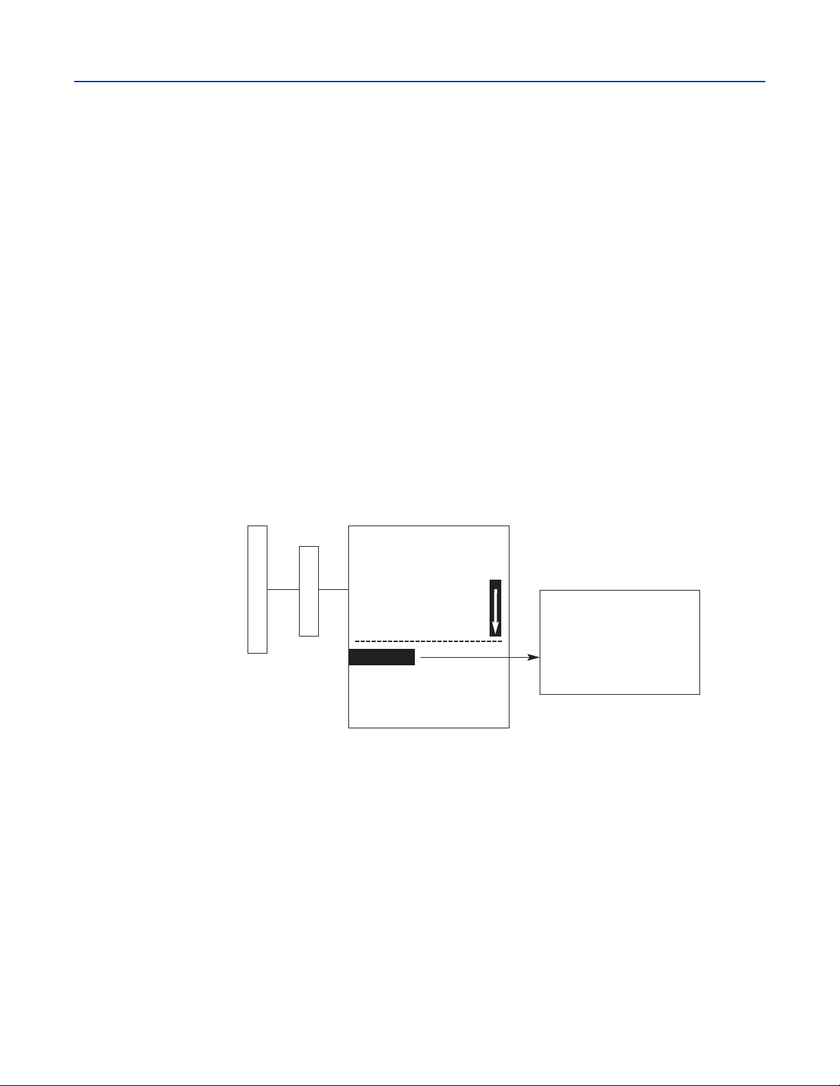
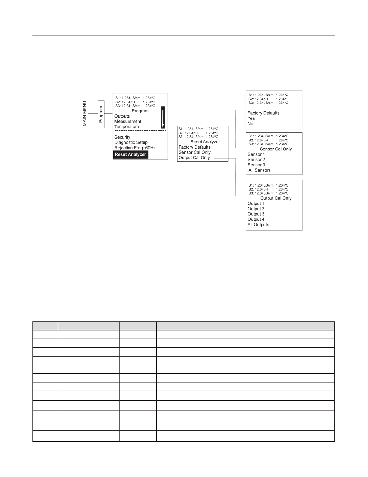
5.8 Resetting the Factory Default Settings
5.8.1 Purpose
This section describes how to restore factory calibration and default values. The process also clears all
fault messages and returns the display to the first Quick Start screen. The Model 1057 offers three
options for resetting factory defaults.
• Reset all settings to factory defaults
• Reset sensor calibration data only
• Reset output calibration only
Section 5: Programming the Analyzer - Basics 25
Page 36
ection 5: Programming the Analyzer - Basics
S
April 2017
5.8.2 Procedure
To reset to factory defaults, reset calibration data only or reset analog outputs only, follow the Reset
Analyzer flow diagram (Figure 5-5).
Figure 5-5 Resetting Factory Default Settings
nstruction Manual
I
LIQ-MAN-1057
5.9 Programming Alarm Relays
5.9.1 Purpose
The Model 1057 24 Vdc (02 order code) and the AC switching power supply (03 order code) provide
four alarm relays for process measurement or temperature. Each alarm can be configured as a fault
alarm instead of a process alarm. Also, each relay can be programmed independently and each can be
programmed as an interval timer. This section describes how to configure alarm relays, simulate relay
activation, and synchronize timers for the four alarm relays. This section provides details to program
the following alarm features:
Table 5-2 Programming alarm relays
Section Alarm Relay Feature
5.9.2 Enter setpoint
5.9.3 Assign measurement
5.9.4 Set relay logic
5.9.5
5.9.6 USP safety
5.9.7
5.9.8 Interval time
5.9.9 On-Time
5.9.10 Recover time
5.9.11 Hold while active
5.9.12 Simulate Manually simulate alarms to confirm relay operation
5.9.13 Synchronize timers
Deadband
Normal state
Default
100.0uS/cm
S1 Measure
High
0.00uS/cm
i
0%
Open
24.0 hr
10 min
60 sec
S1
Yes
Description
Enter alarm trigger value
Select alarm assignment
Program relay to activate at High or Low reading
Program the change in process value after the relay deactivates
Program percentage of the limit to activate the alarm
Program relay default condition as open or closed for failsafe operation
Time in hours between relay activations
Enter the time in seconds that the relay is activated.
Enter time after the relay deactivation for process recovery
Holds current outputs during relay activation
Control the timing of two or more relay timers set as Interval timers
Section 5: Programming the Analyzer - Basics26
Page 37

nstruction Manual
I
LIQ-MAN-1057
Under the Program/Alarms menu, the adjacent screen appears to allow
configuration of the alarm relays. Follow the menu screens in Figure 5-2 to
onfigure the outputs.
c
The adjacent screen appears to allow selection of a specific alarm relay.
Select the desired alarm and press ENTER.
The adjacent screen appears next to allow complete programming of each
alarm. Factory defaults are displayed as they would appear for an installed
contacting conductivity board. USP Safety only appears if alarm logic is set
to “USP”. Interval timer, On Time, Recover Time, and Hold While Active
only appear if the alarm is configured as an Interval timer.
ection 5: Programming the Analyzer - Basics
S
April 2017
1: 1.234µS/cm 1.234°C
S
2: 12.34pH 1.234°C
S
3: 12.34µS/cm 1.234°C
S
Alarms
Configure/Setpoint
Simulate
Synchronize Timers: Yes
1: 1.234µS/cm 1.234°C
S
2: 12.34pH 1.234°C
S
S3: 12.34µS/cm 1.234°C
Configure/Setpoint
Alarm 1
Alarm 2
Alarm 3
Alarm 4
1: 1.234µS/cm 1.234°C
S
S2: 12.34pH 1.234°C
3: 12.34µS/cm 1.234°C
S
AlarmM Settings
Setpoint: 100.0uS/cm
Assign: S1 Measure
Logic: High
Deadband: 0.00uS/cm
USP Safety: 0%
i
Interval time: 24.0 hr
On Time: 120 sec
Recover time: 60 sec
Hold while active: Sens1
5.9.2 Procedure - Enter Setpoints
Under the Program/Alarms menu, the adjacent screen appears to allow
configuration of the alarm relays. Enter the desired value for the process
measurement or temperature at which to activate an alarm event.
5.9.3 Procedure - Assign Measurements
Under the Alarms Settings menu, the adjacent screen appears to allow
assignment of the alarm relays. select an alarm assignment.
Additional assignment choices are shown in Figure 5-2 depending on
which measurement board(s) is installed.
5.9.4 Procedure - Set Relay Logic
Under the Alarms Settings menu, the adjacent screen appears to set the
alarm logic. Select the desired relay logic to activate alarms at a High
reading or a Low reading. USP safety only appears if a contacting
conductivity board is installed.
S1: 1.234µS/cm 1.234°C
S2: 12.34pH 1.234°C
S3: 12.34µS/cm 1.234°C
Alarm1 S2 Setpoint
+100.0uS/cm
S1: 1.234µS/cm 1.234°C
S2: 12.34pH 1.234°C
S3: 12.34µS/cm 1.234°C
AlarmM Assign:
S1 Measurement
S1 Temperature
S2 Measurement
S2 Temperature
S3 Measurement
S3 Temperature
Interval Timer
Fault
Off
S1: 1.234µS/cm 1.234°C
S2: 12.34pH 1.234°C
S3: 12.34µS/cm 1.234°C
AlarmM Logic:
High
Low
USP
Section 5: Programming the Analyzer - Basics 27
Page 38

ection 5: Programming the Analyzer - Basics
S
April 2017
5.9.5 Procedure - Deadband
Under the Alarms Settings menu, the adjacent screen appears to program
the deadband as a measurement value. Enter the change in the process
alue needed after the relay deactivates to return to normal (and thereby
v
preventing repeated alarm activation).
5.9.6 Procedure - USP Safety
Under the Alarms Settings menu, the adjacent screen appears to program
the USP alarm setting. Enter the percentage below the limit at which to
activate the alarm.
5.9.7 Procedure - Normal State
The user can define failsafe condition in software by programming the alarm
default state to normally open or normally closed upon power up. To display
this alarm configuration item, enter the Expert menus by holding down the
EXIT key for six seconds while in the main display mode. Select Yes upon
seeing the screen prompt: “Enable Expert Menu?” Under the Alarms
Settings menu, the adjacent screen appears to set the normal state of the
alarms. Select the alarm condition that is desired each time the analyzer is
powering up.
5.9.8 Procedure - Interval Time
Under the Alarms Settings menu, the adjacent screen appears to set the
interval time. Enter the fixed time in hours between relay activations.
nstruction Manual
I
LIQ-MAN-1057
1: 1.234µS/cm 1.234°C
S
2: 12.34pH 1.234°C
S
3: 12.34µS/cm 1.234°C
S
Alarm1 Deadband
000.5uS/cm
+
1: 1.234µS/cm 1.234°C
S
2: 12.34pH 1.234°C
S
3: 12.34µS/cm 1.234°C
S
Alarm1 USP Safety
i
+0%
S1: 1.234µS/cm 1.234°C
S2: 12.34pH 1.234°C
3: 12.34µS/cm 1.234°C
S
Alarm2 Normal State
Open
Closed
S1: 1.234µS/cm 1.234°C
S2: 12.34pH 1.234°C
S3: 12.34µS/cm 1.234°C
Alarm1 Interval Time
024.0 hrs
5.9.9 Procedure - On Time
Under the Alarms Settings menu, the adjacent screen appears to set the
relay on time. Enter the time in seconds that the relay is activated.
5.9.10 Procedure - Recovery Time
Under the Alarms Settings menu, the adjacent screen appears to set the
relay recovery time. Enter time after the relay deactivation for process
recovery.
5.9.11 Procedure - Hold While Active
Under the Alarms Settings menu, the adjacent screen appears to program
the feature that holds the current outputs while alarms are active. Select to
hold the current outputs for Sensor 1, Sensor 2 or both sensors while the
relay is activated.
S1: 1.234µS/cm 1.234°C
S2: 12.34pH 1.234°C
S3: 12.34µS/cm 1.234°C
Alarm1 On-Time
00.00sec
S1: 1.234µS/cm 1.234°C
S2: 12.34pH 1.234°C
S3: 12.34µS/cm 1.234°C
Alarm1 Recovery
060sec
S1: 1.234µS/cm 1.234°C
S2: 12.34pH 1.234°C
S3: 12.34µS/cm 1.234°C
Alarm1 Hold while
active
Sensor 1
Sensor 2
Sensor 3
All
None
Section 5: Programming the Analyzer - Basics28
Page 39

nstruction Manual
I
LIQ-MAN-1057
5.9.12 Procedure - Simulate
Alarm relays can be manually set for the purposes of checking devices
such as valves or pumps. Under the Alarms Settings menu, the adjacent
creen appears to allow manual forced activation of the alarm relays.
s
Select the desired alarm condition to simulate.
5.9.13 Procedure - Synchronize
Under the Alarms Settings menu, the adjacent screen appears to allow
synchronization of alarms that are set to interval timers. Select Yes or No
to synchronize two or more timers
ection 5: Programming the Analyzer - Basics
S
April 2017
1: 1.234µS/cm 1.234°C
S
S2: 12.34pH 1.234°C
S3: 12.34µS/cm 1.234°C
Simulate Alarm M
on’t simulate
D
De-energize
Energize
S1: 1.234µS/cm 1.234°C
2: 12.34pH 1.234°C
S
3: 12.34µS/cm 1.234°C
S
Synchronize Timers
Yes
No
Section 5: Programming the Analyzer - Basics 29
Page 40

ection 5: Programming the Analyzer - Basics
S
April 2017
nstruction Manual
I
LIQ-MAN-1057
Section 5: Programming the Analyzer - Basics30
Page 41

nstruction Manual
I
LIQ-MAN-1057
ection 6: Programming Measurements
S
Section 6: Programming Measurements
6.1 Programming Measurements - Introduction
The Model 1057 automatically recognizes each installed measurement board upon first power-up and
each time the analyzer is powered. Completion of Quick Start screens upon first power up enable
measurements, but additional steps may be required to program the analyzer for the desired
measurement application. This section covers the following programming and configuration
functions;
1. Selecting measurement type or sensor type (all sections)
2. Identifying the preamp location (pH - see Section 6.2)
3. Enabling manual temperature correction and entering a reference temperature (all sections)
4. Enabling sample temperature correction and entering temperature correction slope (selected sections)
5. Defining measurement display resolution (pH)
6. Defining measurement display units (all sections)
7. Adjusting the input filter to control display and output reading variability or noise (all sections)
8. Selecting a measurement range (conductivity – see Section 6.4)
9. Entering a cell constant for a contacting sensor (see Section 6.4)
10. Entering a temperature element/RTD offset or temperature slope (conductivity - see Section 6.4)
11. Creating an application-specific concentration curve (conductivity - see Section 6.4)
To fully configure the analyzer for each installed measurement board, you may use the following:
1. Reset analyzer function to reset factory defaults and configure the measurement board to the
desired measurement. Follow the Reset Analyzer menu (Figure 5-5) to reconfigure the analyzer to
display new measurements or measurement units.
2. Program menus to adjust any of the programmable configuration items. Use the following
configuration and programming guidelines for the applicable measurement.
April 2017
6.2 pH Measurement Programming
6.2.1 Description
This section describes how to configure the Model 1057 analyzer for pH measurements. The following
programming and configuration functions are covered.
Table 6-1 pH measurement programming
Measure Section Menu Function
pH
Section 6: Programming Measurements 31
6.2.2 Measurement type
6.2.3 Preamp location
6.2.4
6.2.5 Temp coefficient
6.2.6 Resolution
6.2.7 Filter
6.2.8
Solution temperature
correction
Reference Z
Default
Settings
pH
Analyzer
Off
(custom)
0.01pH
4 seconds
Low
Description
Select pH, ORP, redox, ammonia, fluoride, custom ISE
Identify preamp location
Select Off, ultra-pure, high pH, custom
Enter the temp coefficient
Select 0.01pH or 0.1pH for pH display resolution
Override the default input filter, enter 0-999 seconds
Select low or high reference impedance
Page 42

ection 6: Programming Measurements
S
April 2017
detailed flow diagram (Figure 6-1) for pH configuring is provided at the end of Section 6 to guide you
A
through all basic configuration functions.
To configure the pH measurement board:
1. Press MENU
. Scroll down to Program. Press ENTER.
2
3. Scroll down to Measurement. Press ENTER.
4. Select Sensor 1 or Sensor 2 corresponding to pH. Press ENTER.
The adjacent screen format appears (factory defaults are shown).
To program any function, scroll to the desired item and press ENTER.
The following sub-sections provide you with the initial display screen that appears for each
configuration function. Use the flow diagram for configuring pH/ORP measurements (
the end of this section and the Model 1057 live screen prompts for each function to complete
configuration and programming.
6.2.2 Measurement
The display screen for selecting the Measurement is shown. The default
value is displayed in bold type. Refer to configuring pH/ORP
measurements flow diagram (Figure 6-1) to complete this function.
nstruction Manual
I
LIQ-MAN-1057
S1: 1.234µS/cm 1.234°C
2: 12.34pH 1.234°C
S
3: 12.34µS/cm 1.234°C
S
SN Configure
easure: pH
M
Preamp: Analyzer
Sol’n Temp Corr: Off
T Coeff: -0.029pH/°C
Resolution: 0.01pH
Filter: 4 sec
Reference Z: Low
Figure 6-1) at
S1: 1.234µS/cm 1.234°C
S2: 12.34pH 1.234°C
S3: 12.34µS/cm 1.234°C
SN Measurement
pH
ORP
Redox
Ammonia
6.2.3 Preamp
The display screen for identifying the Preamp location is shown. The default
value is displayed in bold type. Refer to configuring pH/ORP
measurements flow diagram (Figure 6-1) to complete this function.
6.2.4 Solution Temperature Correction
The display screen for selecting the Solution Temperature Correction
algorithm is shown. The default value is displayed in bold type. Refer to
configuring pH/ORP measurements flow diagram (Figure 6-1) to complete
this function.
6.2.5 Temperature Coefficient
The display screen for entering the custom Solution Temperature
Coefficient is shown. The default value is displayed in bold type. Refer to
configuring pH/ORP measurements flow diagram (Figure 6-1) to complete this function.
Fluoride
Custom ISE
S1: 1.234µS/cm 1.234°C
S2: 12.34pH 1.234°C
S3: 12.34µS/cm 1.234°C
SN Preamp
Analyzer
Sensor/JBox
S1: 1.234µS/cm 1.234°C
S2: 12.34pH 1.234°C
S3: 12.34µS/cm 1.234°C
SN Sol’n Temp Corr.
Off
Ultra Pure Water
High pH
Custom
S1: 1.234µS/cm 1.234°C
S2: 12.34pH 1.234°C
S3: 12.34µS/cm 1.234°C
SN Sol’n Temp Coeff.
- 0.032pH/ºC
Section 6: Programming Measurements32
Page 43
nstruction Manual
I
LIQ-MAN-1057
6.2.6 Resolution
he display screen for selecting 0.01pH or 0.1pH for pH display Resolution is
T
shown. The default value is displayed in bold type. Refer to configuring
pH/ORP measurements flow diagram (
ection 6: Programming Measurements
S
Figure 6-1) to complete this function.
April 2017
1: 1.234µS/cm 1.234°C
S
S2: 12.34pH 1.234°C
S3: 12.34µS/cm 1.234°C
SN Resolution
.01pH
0
0.1pH
6.2.7 Filter
The display screen for entering the Input filter value in seconds is shown.
The default value is displayed in bold type. Refer to configuring
pH/ORP measurements flow diagram (Figure 6-1) to complete this function.
6.2.8 Reference Impedence
The display screen for selecting Low or High Reference impedance (Z) is
shown. The default value is displayed in bold type. Refer to configuring
pH/ORP measurements flow diagram (Figure 6-1) to complete this function.
6.3 ORP Measurement Programming
6.3.1 Description
The section describes how to configure the Model 1057 analyzer for ORP measurements.
The following programming and configuration functions are covered:
Table 6-2 ORP measurement programming
Measure Section Menu Function
ORP
6.3.2 Measurement type
6.3.3 Preamp location
6.3.4 Filter
6.3.5 Reference (Z)
Default
Settings
pH
Analyzer
4 seconds
Low
Description
Select pH, ORP, redox, ammonia, fluoride, custom ISE
Identify preamp location
Override the default input filter, enter 0-999 seconds
Select low or high reference impedance
S1: 1.234µS/cm 1.234°C
S2: 12.34pH 1.234°C
S3: 12.34µS/cm 1.234°C
SN Input filter
04 sec
1: 1.234µS/cm 1.234°C
S
S2: 12.34pH 1.234°C
S3: 12.34µS/cm 1.234°C
SN Reference Z
Low
High
A detailed flow diagram (Figure 6-1) for configuring ORP measurements is provided at the end of
Section 6 to guide you through all basic configuration functions.
To configure the ORP measurement board:
1. Press MENU.
2. Scroll down to Program. Press ENTER.
3. Scroll down to Measurement. Press ENTER.
4. Select Sensor 1 or Sensor 2 corresponding to ORP. Press ENTER.
The adjacent screen appears (factory defaults are shown). To program
any displayed function, scroll to the desired item and press ENTER.
S1: 1.234µS/cm 1.234°C
S2: 12.34pH 1.234°C
S3: 12.34µS/cm 1.234ºC
SN Configure
Measure: pH
Preamp: Analyzer
Flter: 4 sec
Reference Z: Low
The following sub-sections provide you with the initial display screen that appears for each
configuration function. Use the flow diagram (Figure 6-1) for configuring ORP measurements at the
end of this section and the Model 1057 live screen prompts for each function to complete
configuration and programming.
Section 6: Programming Measurements 33
Page 44

ection 6: Programming Measurements
S
April 2017
6.3.2 Measurement
The display screen for selecting the Measurement is shown. The default
value is displayed in bold type. Refer to configuring pH/ORP measurements
flow diagram (Figure 6-1) to complete this function.
6.3.3 Preamp
The display screen for identifying the Preamp location is shown. The default
value is displayed in bold type. Refer to configuring pH/ORP measurements
flow diagram (Figure 6-1) to complete this function.
6.3.4 Filter
The display screen for entering the Input filter value in seconds is shown.
The default value is displayed in bold type. Refer to configuring pH/ORP
measurements flow diagram (Figure 6-1) to complete this function.
nstruction Manual
I
LIQ-MAN-1057
1: 1.234µS/cm 1.234°C
S
2: 12.34pH 1.234°C
S
3: 12.34µS/cm 1.234°C
S
SN Measurement
pH
ORP
Redox
Ammonia
Fluoride
ustom ISE
C
1: 1.234µS/cm 1.234°C
S
2: 12.34pH 1.234°C
S
3: 12.34µS/cm 1.234°C
S
SN Preamp
Analyzer
Sensor/JBox
1: 1.234µS/cm 1.234°C
S
S2: 12.34pH 1.234°C
S3: 12.34µS/cm 1.234°C
SN Input filter
04 sec
S1: 1.234µS/cm 1.234°C
6.3.5 Reference Impedence
The display screen for Selecting Low or high Reference impedance (Z) is
shown. The default value is displayed in bold type. Refer to configuring
pH/ORP measurements flow diagram (Figure 6-1) to complete this function.
S2: 12.34pH 1.234°C
S3: 12.34µS/cm 1.234°C
SN Reference Z
Low
High
6.4 Contacting Conductivity Measurement Programming
6.4.1 Description
The section describes how to configure the Model 1057 analyzer for conductivity measurements
using contacting conductivity sensors. The following programming and configuration functions
are covered.
Table 6-3 Contacting conductivity measurement programming
Measure Section Menu Function:
Contacting
Conductivity
6.4.2 Type
6.4.3 Measure
6.4.4 Range
6.4.5 Cell K
6.4.6 RTD Offset
6.4.7 RTD Slope
6.4.8 Temp Comp
6.4.9 Slope 2.00%/°C Enter the linear temperature coefficient
6.4.10 Ref Temp 25.0 °C Enter the Reference temp
6.4.11 Filter 2 seconds Override the default input filter, enter 0-999 seconds
6.4.12 Custom Setup Enter 2-5 data points in ppm and µS/cm for custom curves
6.4.13 Cal Factor 0.95000/cm Enter the Cal Factor for 4-Electrode sensors from the sensor tag
Default
Settings
2- Electrode
Conductivity
Auto
1.00000/cm
0.00°C
0
Slope
Description
Select 2-Electrode or 4-Electrode type sensors
Select Conductivity, Resistivity, TDS. Salinity or % conc
Select measurement Auto-range or specific range
Enter the cell Constant for the sensor
Enter the RTD Offset
Enter the RTD Slope
Select Temp Comp: Slope, Neutral Salt, Cation or Raw
Section 6: Programming Measurements34
Page 45

nstruction Manual
I
LIQ-MAN-1057
A detailed flow diagram (Figure 6-2) for contacting conductivity programming is provided at the end
of this section to guide you through all basic programming and configuration functions.
To configure the contacting conductivity measurement board:
. Press MENU
1
. Scroll down to Program. Press ENTER.
2
3. Scroll down to Measurement. Press ENTER.
4. Select Sensor 1 or Sensor 2 corresponding to contacting conductivity.
Press ENTER.
The adjacent screen appears (factory defaults are shown).
To program any displayed function, scroll to the desired item and press ENTER.
The following sub-sections provide you with the initial display screen that appears for each
configuration function. Use the flow diagram for contacting conductivity programming at the end of
this section and the Model 1057 live screen prompts for each function to complete configuration
and programming.
ection 6: Programming Measurements
S
April 2017
1: 1.234µS/cm 1.234°C
S
S2: 12.34pH 1.234°C
S3: 12.34µS/cm 1.234°C
SN Configure
Type: 2-Electrode
Measure: Cond
Range: Auto
Cell K: 1.00000/cm
RTD Offset: 0.00°C
RTD Slope: 0
Temp Comp: Slope
Slope: 2.00%/°C
Ref Temp: 25.0°C
Filter: 2 sec
Custom Setup
6.4.2 Sensor Type
The display screen for selecting 2-Electrode or 4-Electrode Type sensors is
shown. The default value is displayed in bold type. Refer to configuring
contacting measurements flow diagram (Figure 6-2) to complete this function.
6.4.3 Measure
The display screen for selecting the Measurement is shown.
The default value is displayed in bold type. Refer to configuring
contacting measurements flow diagram (Figure 6-2) to complete this function.
6.4.4 Range
The display screen for selecting Range (Auto or a specific range) is shown.
The default value is displayed in bold type.
Note: Ranges are shown as conductance, not conductivity.
Refer to configuring contacting measurements flow diagram (Figure 6-2) to
complete this function.
S1: 1.234µS/cm 1.234°C
S2: 12.34pH 1.234°C
S3: 12.34µS/cm 1.234°C
SN Type
2-Electrode
4-Electrode
S1: 1.234µS/cm 1.234°C
S2: 12.34pH 1.234°C
S3: 12.34µS/cm 1.234°C
SN Measurement
Conductivity
Resistivity
TDS
Salinity
NaOH (0-12%)
HCl (0-15%)
Low H2SO4
High H2SO4
NaCl (0-20%)
Custom Curve
S1: 1.234µS/cm 1.234°C
S2: 12.34pH 1.234°C
S3: 12.34µS/cm 1.234°C
SN Range
Auto
50 µS
500 µS
2000 µS
20 mS
200 mS
600 mS
Section 6: Programming Measurements 35
Page 46

ection 6: Programming Measurements
S
April 2017
nstruction Manual
I
LIQ-MAN-1057
6.4.5 Cell Constant
The display screen for entering a cell Constant for the sensor is shown.
The default value is displayed in bold type. Refer to configuring contacting
measurements flow diagram (Figure 6-2) to complete this function.
6.4.6 RDT Offset
The display screen for entering the RTD Offset for the sensor is shown.
The default value is displayed in bold type. Refer to configuring contacting
measurements flow diagram (Figure 6-2) to complete this function.
6.4.7 RDT Slope
The display screen for entering the RTD Slope for the sensor is shown.
The default value is displayed in bold type. Refer to configuring contacting
measurements flow diagram (Figure 6-2) to complete this function.
6.4.8 Temp Comp
The display screen for selecting Temperature Compensation as Slope, Neutral
Salt, Cation or Raw is shown. The default value is displayed in bold type.
Refer to configuring contacting measurements flow diagram (Figure 6-2) to
complete this function.
1: 1.234µS/cm 1.234°C
S
2: 12.34pH 1.234°C
S
3: 12.34µS/cm 1.234°C
S
SN Cell Constant
1.00000 /cm
1: 1.234µS/cm 1.234°C
S
S2: 12.34pH 1.234°C
S3: 12.34µS/cm 1.234°C
N RTD Offset
S
0.00°C
S1: 1.234µS/cm 1.234°C
2: 12.34pH 1.234°C
S
3: 12.34µS/cm 1.234°C
S
SN RTD Slope
2.00%/°C
S1: 1.234µS/cm 1.234°C
2: 12.34pH 1.234°C
S
S3: 12.34µS/cm 1.234°C
SN Temp Comp
Slope
Neutral Salt
Cation
Raw
6.4.9 Slope
The display screen for entering the conductivity/temp Slope is shown. The
default value is displayed in bold type. Refer to configuring contacting
measurements flow diagram (Figure 6-2) to complete this function.
6.4.10 Reference Temp
The display screen for entering the Reference Temperature is shown.
The default value is displayed in bold type. Refer to configuring contacting
measurements flow diagram (Figure 6-2) to complete this function.
6.4.11 Filter
The display screen for entering Input filter value is shown in seconds.
The default value is displayed in bold type. Refer to configuring contacting
measurements flow diagram (Figure 6-2) to complete this function.
S1: 1.234µS/cm 1.234°C
S2: 12.34pH 1.234°C
S3: 12.34µS/cm 1.234°C
SN Slope
2.00 %/°C
S1: 1.234µS/cm 1.234°C
S2: 12.34pH 1.234°C
S3: 12.34µS/cm 1.234°C
SN Ref Temp
(25.0°C normal)
+25.0°C
S1: 1.234µS/cm 1.234°C
S2: 12.34pH 1.234°C
S3: 12.34µS/cm 1.234°C
SN Input filter
02 sec
Section 6: Programming Measurements36
Page 47

nstruction Manual
I
LIQ-MAN-1057
6.4.12 Custom Setup
The display screens for creating a Custom Curve for converting conductivity to
concentration is shown. Refer to configuring contacting measurements flow
iagram (Figure 6-2) to complete this function.
d
When the custom curve data entry is complete, press ENTER. The display
confirms the determination of a custom curve fit to the entered data by
displaying this screen:
If the custom curve fit is not completed or is unsuccessful, the adjacent screen
appears and the screen returns to the beginning custom curve screen.
ection 6: Programming Measurements
S
April 2017
1: 1.234µS/cm 1.234°C
S
S2: 12.34pH 1.234°C
S3: 12.34µS/cm 1.234°C
SN Custom Curve
Configure
Enter Data Points
Calculate Curve
1: 1.234µS/cm 1.234°C
S
S2: 12.34pH 1.234°C
S3: 12.34µS/cm 1.234°C
SN Calculate Curve
Custom curve
fit completed.
In Process Cal
recommended.
S1: 1.234µS/cm 1.234°C
S2: 12.34pH 1.234°C
3: 12.34µS/cm 1.234°C
S
SN Calculate Curve
Failure
6.4.13 Cal Factor
Upon initial installation and power up, if 4-electrode was selected for the sensor type in the Quick Start
menus, the user enters a Cell Constant and a Cal Factor using the instrument keypad.
The cell constant is needed to convert measured conductance to conductivity as displayed on the
analyzer screen. The Cal Factor entry is needed which increases the accuracy of the live conductivity
readings, especially at low conductivity readings below 20uS/cm. Both the Cell Constant and the
Cal Factor are printed on the tag attached to the 4-electrode sensor/cable.
The display screen for entering Cal Factor is shown. The default value is
displayed in bold type. If necessary after initial installation and start-up,
enter the Cal Factor as printed on the sensor tag.
S1: 1.234µS/cm 1.234°C
S2: 12.34pH 1.234°C
S3: 12.34µS/cm 1.234°C
SN Cal Factor
0
.95000/cm
Section 6: Programming Measurements 37
Page 48
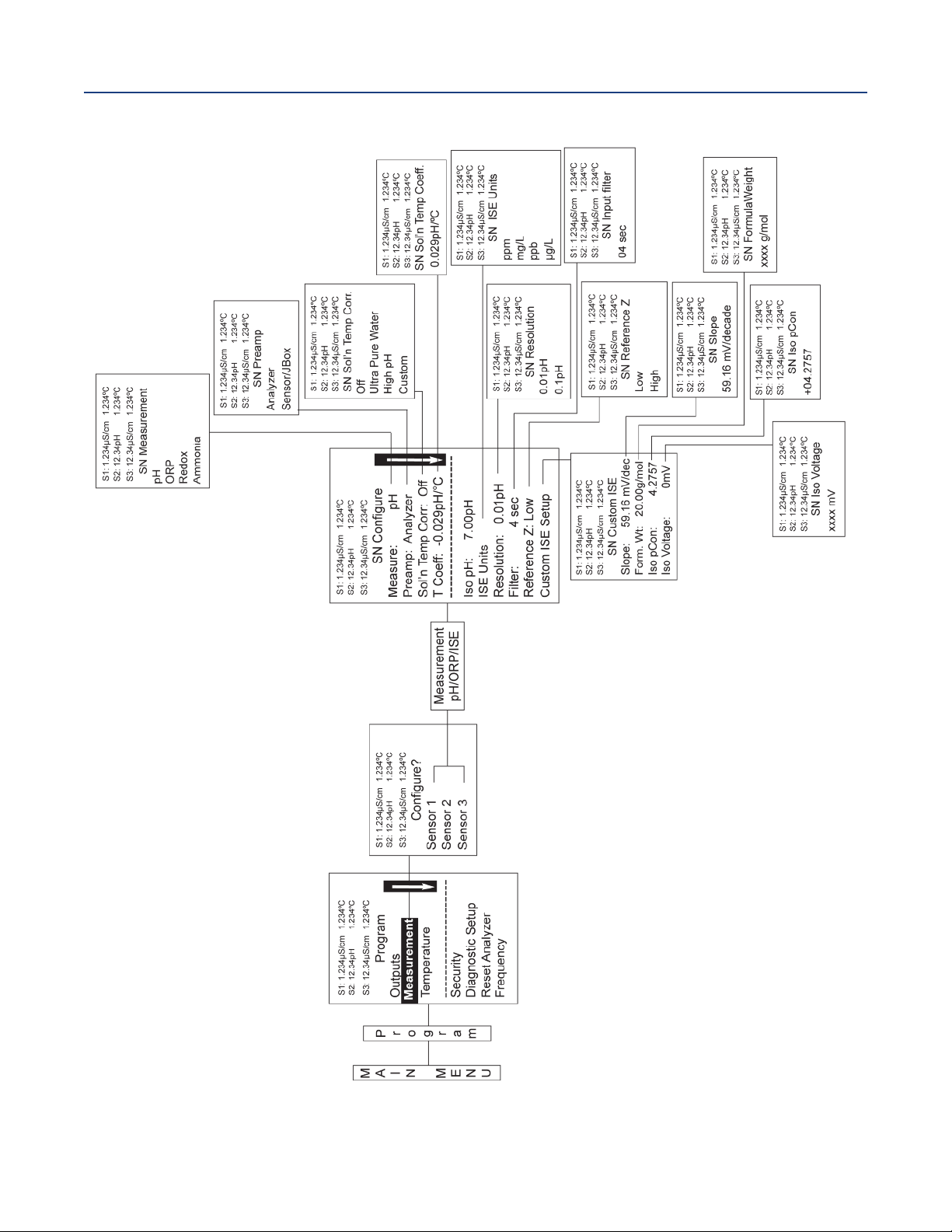
ection 6: Programming Measurements
S
April 2017
Figure 6-1 Configuring pH/ORP Measurements
nstruction Manual
I
LIQ-MAN-1057
Section 6: Programming Measurements38
Page 49
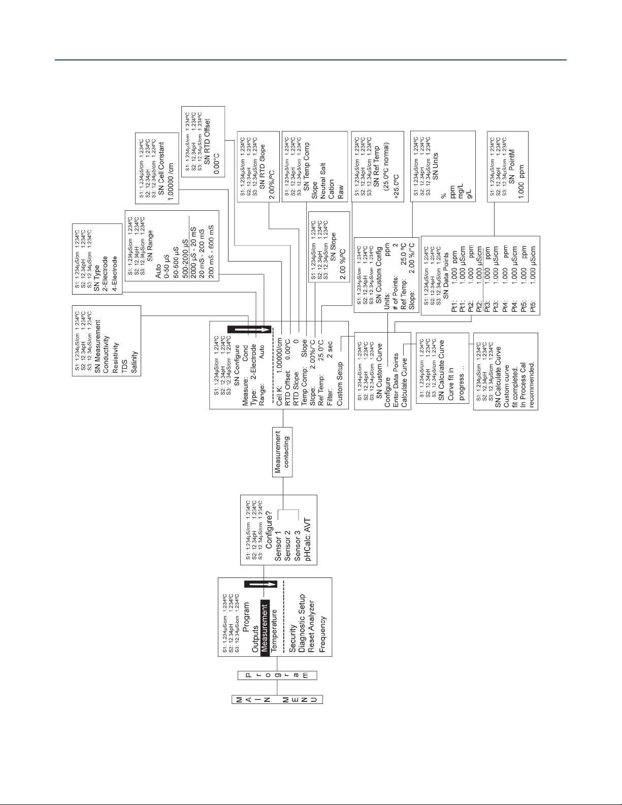
nstruction Manual
I
LIQ-MAN-1057
Figure 6-2 Configuring Contacting Measurements
ection 6: Programming Measurements
S
April 2017
Section 6: Programming Measurements 39
Page 50

ection 6: Programming Measurements
S
April 2017
nstruction Manual
I
LIQ-MAN-1057
Section 6: Programming Measurements40
Page 51

nstruction Manual
I
LIQ-MAN-1057
Section 7: Calibration
7.1 Calibration - Introduction
Calibration is the process of adjusting or standardizing the analyzer to a lab test or a calibrated
laboratory instrument, or standardizing to some known reference (such as a commercial buffer).
The auto-recognition feature of the analyzer will enable the appropriate calibration screens to allow
calibration for any single sensor configuration or dual sensor configuration of the analyzer.
Completion of Quick Start upon first power up enables live measurements but does not ensure
accurate readings in the lab or in process. Calibration should be performed with each attached
sensor to ensure accurate, repeatable readings. This section covers the following programming and
configuration functions:
1. Auto buffer cal for pH (pH Cal -
2. Manual buffer cal for pH (pH Cal - Section 7.2)
3. Set calibration stabilization criteria for pH (pH Cal - Section 7.2)
4. Standardization calibration (1-point) for pH, ORP and Redox (pH Cal - Section 7.2 and 7.3)
5. Entering the cell constant of a conductivity sensor (Conductivity Cal - Section 7.4 and 7.5)
6. Calibrating the sensor in a conductivity standard (Conductivity Cal - Section 7.4 and 7.5)
7. Calibrating the analyzer to a laboratory instrument (Conductivity Cal - Section 7.4)
8. Enter a manual reference temperature for temperature compensation of the process measurement
Section 7.2)
ection 7: Calibration
S
April 2017
7.2 pH Calibration
7.2.1 Description
New sensors must be calibrated before use. Regular recalibration is also necessary. Use auto
calibration instead of manual calibration. Auto calibration avoids common pitfalls and reduces errors.
The analyzer recognizes the buffers and uses temperature-corrected pH values in the calibration.
Once the Model 1057 successfully completes the calibration, it calculates and displays the calibration
slope and offset. The slope is reported as the slope at 25 °C. This section describes how to calibrate the
model 1057 with a ph sensor. the following calibration routines are covered.
Table 7-1 pH calibration routines
Measure Section Menu Function
pH
7.2.2 Auto Calibration
7.2.3 Manual Calibration
7.2.4
7.2.5 Standardization
Entering A Known
Slope Value
A detailed flow diagram is provided at the end of this section to guide you through the calibration
routines.
To calibrate pH:
1. Press the MENUbutton
2. Select Calibrate. Press ENTER.
3. Select Sensor 1or Sensor 2 corresponding to pH. Press ENTER.
4. Select pH. Press ENTER.
Default
Settings
pH
pH
pH
pH
Description
Two point buffer calibration with auto buffer recognition
Two point buffer calibration with manual buffer value entry
Slope calibration with manual entry of known slope value
One point buffer calibration with manual buffer value entry
Section 7: Calibration 41
Page 52

ection 7: Calibration
S
April 2017
The adjacent screen appears. To Calibrate pH or Temperature scroll to the
desired item and press ENTER.
The following sub-sections show the initial display screen that appears for each calibration routine.
Use the flow diagram (Figure 7-1) for pH calibration at the end of this section and the live screen
prompts to complete calibration.
7.2.2 Auto Calibration - pH
This screen appears after selecting pH cal.
Note that pH auto calibration criteria can be changed.
The following criteria can be adjusted:
• Stabilization time (default 10 seconds)
• Stabilization pH value (default 0.02 pH)
• Type of Buffer used for AUTO CALIBRATION (default is Standard, non-commercial buffers).
The following commercial buffer tables are recognized by the analyzer:
nstruction Manual
I
LIQ-MAN-1057
1: 1.234µS/cm 1.234°C
S
2: 12.34pH 1.234°C
S
S3: 12.34µS/cm 1.234°C
SN Calibrate?
pH
Temperature
S1: 1.234µS/cm 1.234°C
2: 12.34pH 1.234°C
S
3: 12.34µS/cm 1.234°C
S
SN pH Cal
Buffer Cal
Standardize
Slope: 59.16mV/pH
Offset: 600 mV
• Standard (NIST plus pH7)
• DIN 19267
• Ingold
• Merck
The adjacent screen appears to allow adjustment of above criteria:
The adjacent screen appears if the Auto Calis successful. The screen returns
to the pH Buffer Cal menu.
The following screen appears if the Auto Calis unsuccessful.
1. A High Slope Errorgenerates the adjacent screen display:
S1: 1.234µS/cm 1.234°C
S2: 12.34pH 1.234°C
S3: 12.34µS/cm 1.234°C
SN Setup
Stable Time: 10 sec
Stable Delta: 0.02 pH
Buffer: Standard
S1: 1.234µS/cm 1.234°C
S2: 12.34pH 1.234°C
S3: 12.34µS/cm 1.234°C
SN pH Auto Cal
Slope: 59.16 mV/pH
Offset: 60 mV
S1: 1.234µS/cm 1.234°C
S2: 12.34pH 1.234°C
S3: 12.34µS/cm 1.234°C
SN pH Auto Cal
High Slope Error
Calculated: 62.11 mV/pH
Max: 62.00 mV/pH
Press EXIT
2. A Low Slope Errorgenerates the adjacent screen display:
S1: 1.234µS/cm 1.234°C
S2: 12.34pH 1.234
S3: 12.34µS/cm 1.234
°C
°C
SN pH Auto Cal
Low Slope Error
Calculated: 39.11mV/pH
Min: 40.00 mV/pH
Press EXIT
Section 7: Calibration 42
Page 53

nstruction Manual
I
LIQ-MAN-1057
3. An Offset Errorgenerates the adjacent screen display:
7.2.3 Manual Calibration - pH
New sensors must be calibrated before use. Regular recalibration is also necessary. Use manual
calibration if non-standard buffers are being used; otherwise, use auto calibration.
Auto calibration avoids common pitfalls and reduces errors.
The adjacent screen appears after selecting pH Manual cal.
7.2.4 Entering A Known Slope Value — pH
If the electrode slope is known from other measurements, it can be entered
directly in the Model 1057 analyzer. The slope must be entered as the
Slope at 25 °C.
ection 7: Calibration
S
April 2017
S1: 1.234µS/cm 1.234°C
2: 12.34pH 1.234°C
S
3: 12.34µS/cm 1.234°C
S
SN pH Auto Cal
Offset Error
Calculated: 61.22mV
ax: 60.00mV
M
Press EXIT
S1: 1.234µS/cm 1.234°C
2: 12.34pH 1.234°C
S
3: 12.34µS/cm 1.234°C
S
SN pH Manual Cal
Buffer 1
Buffer 2
S1: 1.234µS/cm 1.234°C
S2: 12.34pH 1.234°C
S3: 12.34µS/cm 1.234°C
SN pH Slope@25°C
59.16 mV/pH
7.2.5 Standardization — pH
The pH measured by the Model 1057 analyzer can be changed to match the
reading from a second or referee instrument. The process of making the two
readings agree is called standardization. During standardization, the
difference between the two pH values is converted to the equivalent voltage.
The voltage, called the reference offset, is added to all subsequent measured
cell voltages before they are converted to pH. If a standardized sensor is placed
in a buffer solution, the measured pH will differ from the buffer pH by an
amount equivalent to the standardization offset.
The following screen may appear if ORP Cal is unsuccessful.
An Offset Error generates the adjacent screen display:
If the ORP Cal is successful, the screen returns to the Cal sub-menu.
S1: 1.234µS/cm 1.234°C
S2: 12.34pH 1.234°C
S3: 12.34µS/cm 1.23°C
SN Enter Value
07.00pH
S1: 1.234µS/cm 1.234°C
S2: 12.34pH 1.234°C
S3: 12.34µS/cm 1.234°C
SN Standardize
Offset Error
Calculated: 96mV
Max: 60mV
Press EXIT
Section 7: Calibration 43
Page 54

ection 7: Calibration
S
April 2017
nstruction Manual
I
LIQ-MAN-1057
7.3 ORP Calibration
7.3.1 Description
or process control, it is often important to make the measured ORP agree with the ORP of a standard
F
solution. During calibration, the measured ORP is made equal to the ORP of a standard solution
at a single point.
This section describes how to calibrate the model 1057 with ORP sensor. The following calibration
routine is covered.
Table 7-2 ORP calibration routine
Measure Section Menu Function
ORP 7.3.2 Standardization ORP One point buffer calibration with manual buffer value entry
Default
Settings
Description
A detailed flow diagram (
Figure 7-2) is provided at the end of this section to guide you through the
ORP calibration routines.
To calibrate ORP:
1. Press the MENU button
2. Select Calibrate. Press ENTER.
3. Select Sensor 1 or Sensor 2 corresponding to ORP. Press ENTER.
4. Select ORP. Press ENTER.
The adjacent screen appears. To calibrate ORP or Temperature, scroll to
the desired item and press ENTER.
The following sub-sections show the initial display screen that appears for each calibration routine.
Use the flow diagram (Figure 7-2) for ORP calibration at the end of this section and the live screen
prompts to complete calibration.
7.3.1 Standardization — ORP
For process control, it is often important to make the measured ORP agree with the ORP of a standard
solution. During calibration, the measured ORP is made equal to the ORP of a standard solution at a
single point.
The adjacent screen appears after selecting ORP calibration.
If the ORP Cal is successful, the screen returns to the Cal sub-menu.
S1: 1.234µS/cm 1.234°C
S2: 12.34pH 1.234
S3: 12.34µS/cm 1.234
SN Calibrate?
ORP
Temperature
S1: 1.234µS/cm 1.234°C
S2: 12.34pH 1.234
S3: 12.34µS/cm 1.234
SN Enter Value
+0600 mV
°C
°C
°C
°C
The adjacent screen appears if ORP Cal is unsuccessful.
S1: 1.234µS/cm 1.234°C
S2: 12.34pH 1.234
S3: 12.34µS/cm 1.234
SN Standardize
Offset Error
Calculated: 61.22mV
Max: 60.00mV
Press EXIT
Section 7: Calibration44
°C
°C
Page 55

nstruction Manual
I
LIQ-MAN-1057
7.4 Contacting Conductivity Calibration
7.4.1 Description
his section describes how to calibrate a Model 1057 with Contacting Conductivity Sensor attached.
T
Placing A New Conductivity Sensor In Service
New conductivity sensors rarely need calibration. The cell constant printed on the label is sufficiently
accurate for most applications.
Calibrating An In-Service Conductivity Sensor
After a conductivity sensor has been in service for a period of time, recalibration may be necessary.
There are three ways to calibrate a sensor.
1. Use a standard instrument and sensor to measure the conductivity of the process stream. It is
not necessary to remove the sensor from the process piping. The temperature correction
used by the standard instrument may not exactly match the temperature correction used by
the Model 1057. To avoid errors, turn off temperature correction in both the analyzer and the
standard instrument.
2. Place the sensor in a solution of known conductivity and make the analyzer reading match the
conductivity of the standard solution. Use this method if the sensor can be easily removed
from the process piping and a standard is available. Be careful using standard solutions
having conductivity less than 100 µS/cm. Low conductivity standards are highly susceptible
to atmospheric contamination. Avoid calibrating sensors with 0.01/cm cell constants against
conductivity standards having conductivity greater than 100 µS/cm. The resistance of these
solutions may be too low for an accurate measurement. Calibrate sensors with 0.01/cm cell
constant using method 3.
3. To calibrate a 0.01/cm sensor, check it against a standard instrument and 0.01/cm sensor
while both sensors are measuring water having a conductivity between 5 and 10 µS/cm. To
avoid drift caused by absorption of atmospheric carbon dioxide, saturate the sample with air
before making the measurements.
To ensure adequate flow past the sensor during calibration, take the sample downstream
from the sensor. For best results, use a flow-through standard cell. If the process temperature
is much different from ambient, keep connecting lines short and insulate the flow cell.
ection 7: Calibration
S
April 2017
Table 7-3 Contacting conductivity calibration routines
Measure Section Menu Function
Contacting
Conductivity
7.4.2
7.4.3
7.4.4
7.4.5
7.4.6
Cell K 1.00000/cm Enter the cell Constant for the sensor
Zero Cal Zero the analyzer with the sensor attached
In Process Cal Standardize the sensor to a known conductivity
Meter Cal Calibrate the analyzer to a lab conductivity instrument
Cal Factor 0.95000/cm Enter the Cal Factor for 4-Electrode sensors from the sensor tag
Default
Settings
Description
A detailed flow diagram (Figure 7-3) is provided at the end of this section to guide you through the
calibration routines.
To calibrate contacting conductivity:
1. Press the MENU button
2. Select Calibrate. Press ENTER.
3. Select Sensor 1 or Sensor 2 corresponding to contacting conductivity. Press ENTER.
4. Select Conductivity. Press ENTER.
Section 7: Calibration 45
Page 56

ection 7: Calibration
S
April 2017
The adjacent screen appears. To calibrate Conductivity or Temperature, scroll
o the desired item and press ENTER.
t
The following sub-sections show the initial display screen that appears for each calibration routine.
Use the flow diagram (
Figure 7-3) for conductivity calibration at the end of this section and the live
screen prompts for each routine to complete calibration.
The adjacent screen appears after selecting conductivity Calibration.
7.4.2 Entering The Cell Constant
New conductivity sensors rarely need calibration. The cell constant printed on the label is sufficiently
accurate for most applications. The cell constant should be entered:
nstruction Manual
I
LIQ-MAN-1057
1: 1.234µS/cm 1.234
S
S2: 12.34pH 1.234
3: 12.34µS/cm 1.234
S
°C
°C
°C
SN Calibrate?
Conductivity
Temperature
1: 1.234µS/cm 1.234
S
S2: 12.34pH 1.234
3: 12.34µS/cm 1.234
S
°C
°C
°C
SN Calibration
Zero Cal
In Process Cal
Meter Cal
Cell K: 1.00000/cm
• When the unit is installed for the first time
• When the probe is replaced
The display screen for entering Cell Constant for the sensor is shown.
The default value is displayed in bold type.
7.4.3 Zeroing The Instrument
This procedure is used to compensate for small offsets to the conductivity signal that are present even
when there is no conductivity to be measured. This procedure is affected by the length of extension
cable and should always be repeated if any changes in extension cable or sensor have been made.
Electrically connect the conductivity probe as it will actually be used and place the measuring portion
of the probe in air. Be sure the probe is dry.
The adjacent screen appears after selecting Zero Cal from the
conductivity calibration screen.
The adjacent screen appears if Zero Cal is successful. The screen returns to
the conductivity Cal menu.
S1: 1.234µS/cm 1.234°C
S2: 12.34pH 1.234
S3: 12.34µS/cm 1.234
SN Cell Constant
1.00000 /cm
S1: 1.234µS/cm 1.234°C
S2: 12.34pH 1.234
S3: 12.34µS/cm
°CSN Zero Cal
1.234
In Air
In Water
S1: 1.234µS/cm 1.234°C
S2: 12.34pH 1.234
S3: 12.34µS/cm 1.234
SN Zero Cal
Sensor Zero Done
°C
°C
°C
°C
°C
The adjacent screen appears if Zero Cal is unsuccessful.
S1: 1.234µS/cm 1.234°C
S2: 12.34pH 1.234
S3: 12.34µS/cm 1.234
°C
SN Zero Cal
Sensor Zero Fail
Offset too high
Press EXIT
Section 7: Calibration46
°C
Page 57

nstruction Manual
I
LIQ-MAN-1057
ection 7: Calibration
S
7.4.4 Calibrating The Sensor In A Conductivity Standard (In Process Cal)
This procedure is used to calibrate the sensor and analyzer against a solution of known conductivity.
This is done by submerging the probe in the sample of known conductivity, then adjusting the dis
played value, if necessary, to correspond to the conductivity value of the sample. Turn temperature
correction off and use the conductivity of the standard. Use a calibrated thermometer to measure
emperature. The probe must be cleaned before performing this procedure.
t
The adjacent screen appears after selecting In Process Cal from the
conductivity calibration screen.
The adjacent screen appears if In Process Cal is successful. The screen returns
to the conductivity Cal menu.
1: 1.234µS/cm 1.234
S
S2: 12.34pH 1.234
S3: 12.34µS/cm 1.234
N InProcess Cal
S
Wait for stable
reading.
S1: 1.234µS/cm 1.234°C
2: 12.34pH 1.234
S
S3: 12.34µS/cm 1.234
SN InProcess Cal
Updated cell
constant:
1.00135/cm
April 2017
°C
°C
°C
°C
°C
1: 1.234µS/cm 1.234
S
S2: 12.34pH 1.234
The adjacent screen may appear if In Process Cal is unsuccessful. The screen
returns to the conductivity Cal menu.
S3: 12.34µS/cm 1.234
SN InProcess Cal
Calibration
Error
Press EXIT
7.4.5 Calibrating The Sensor To A Laboratory Instrument (Meter Cal)
This procedure is used to check and correct the conductivity reading of the Model 1057 using a
laboratory conductivity instrument. This is done by submerging the conductivity probe in a bath and
measuring the conductivity of a grab sample of the same bath water with a separate laboratory
instrument. The Model 1057 reading is then adjusted to match the conductivity reading of the
lab instrument.
The adjacent screen appears after selecting Meter Cal from the conductivity
calibration screen
After pressing ENTER, the display shows the live value measured by the sensor.
If the Meter Cal is successful the screen returns to the conductivity Cal menu.
S1: 1.234µS/cm 1.234°C
S2: 12.34pH 1.234
S3: 12.34µS/cm 1.234
SN Meter Cal
Use precision
resistors only
S1: 1.234µS/cm 1.234°C
S2: 12.34pH 1.234
S3: 12.34µS/cm 1.234
SN Enter Value
xx.xx kΩ
°C
°C
°C
°C
°C
°C
°C
The adjacent screen appears if Meter Cal is unsuccessful. The screen
returns to the conductivity Cal menu.
S1: 1.234µS/cm 1.234°C
S2: 12.34pH 1.234
S3: 12.34µS/cm 1.234
SN Meter Cal
Calibration
°C
°C
Error
Press EXIT
Section 7: Calibration 47
Page 58

ection 7: Calibration
S
April 2017
7.4.6 Cal Factor
Upon initial installation and power up, if 4-electrode was selected for the sensor type in the Quick Start
menus, the user enters Cell Constant and Cal Factor using the instrument keypad. The cell
onstant is needed to convert measured conductance to conductivity as displayed on the analyzer
c
screen. The Cal Factor entry is needed to increase the accuracy of the live conductivity readings,
especially at low conductivity readings below 20 uS/cm. Both the Cell Constant and the Cal Factor
are printed on the tag attached to the 4-electrode sensor/cable.
The display screen for entering Cal Factor is shown. The default value is
displayed in bold type. If necessary after initial installation and start-up, enter
the Cal Factor as printed on the sensor tag.
7.5 Calibrating Temperature
7.5.1 Description
Most liquid analytical measurements require temperature compensation (except ORP). The Model
1057 performs temperature compensation automatically by applying internal temperature correction
algorithms. Temperature correction can also be turned off. If temperature correction is off, the Model
1057 uses the manual temperature entered by the user in all temperature correction calculations.
This section describes how to calibrate temperature in the model 1057 analyzer. the following
calibration routine is covered.
Table 7-4 Temperature calibration routine
Default
Measure Section Menu Function
Settings
Description
nstruction Manual
I
LIQ-MAN-1057
1: 1.234µS/cm 1.234
S
S2: 12.34pH 1.234
3: 12.34µS/cm 1.234
S
SN Cal Factor
0.95000 /cm
°C
°C
°C
Temperature 7.5.2 Calibrate Enter a manual reference temperature for temperature
compensation of the process measurement
To calibrate temperature:
1. Press the MENU button
2. Select Calibrate. Press ENTER.
3. Select Sensor 1 or Sensor 2 corresponding to the desired
measurement. Press ENTER.
4. Select Temperature. Press ENTER.
S1: 1.234µS/cm 1.234°C
S2: 12.34pH 1.234
S3: 12.34µS/cm 1.234
SN Calibrate
+025.0°C
The adjacent screen appears.
The following sub-section provides you with the initial display screen that appears for temperature
calibration. Use the flow diagram (Figure 7-4) for temperature calibration at the end of this section to
complete calibration.
7.5.2 Calibration
The adjacent screen appears during Temperature Cal.
If the sensor Temperature offset is greater than 5 °C from the default value, the
adjacent screen appears. You may continue by selecting Yes or suspend this
operation by selecting No. If the Temp Cal is successful, the screen returns to
the Cal menu.
Note: To select automatic or manual temp compensation or to program
temperature units as °C or °F, refer to Section 5.3 in this manual
S1: 1.234µS/cm 1.234°C
S2: 12.34pH 1.234
S3: 12.34µS/cm 1.234
SN Calibrate
Cal in progress.
Please wait.
S1: 1.234µS/cm 1.234°C
S2: 12.34pH 1.234
S3: 12.34µS/cm 1.234
SN Temp Offset > 5°C
Continue?
No
Yes
°C
°C
°C
°C
°C
°C
Section 7: Calibration48
Page 59

nstruction Manual
I
LIQ-MAN-1057
Figure 7-1 Calibrate pH
ection 7: Calibration
S
April 2017
Section 7: Calibration 49
Page 60

ection 7: Calibration
S
April 2017
Figure 7-2 Calibrate ORP
nstruction Manual
I
LIQ-MAN-1057
Section 7: Calibration50
Page 61

nstruction Manual
I
LIQ-MAN-1057
igure 7-3 Calibrate Contacting Conductivity
F
ection 7: Calibration
S
April 2017
Section 7: Calibration 51
Page 62
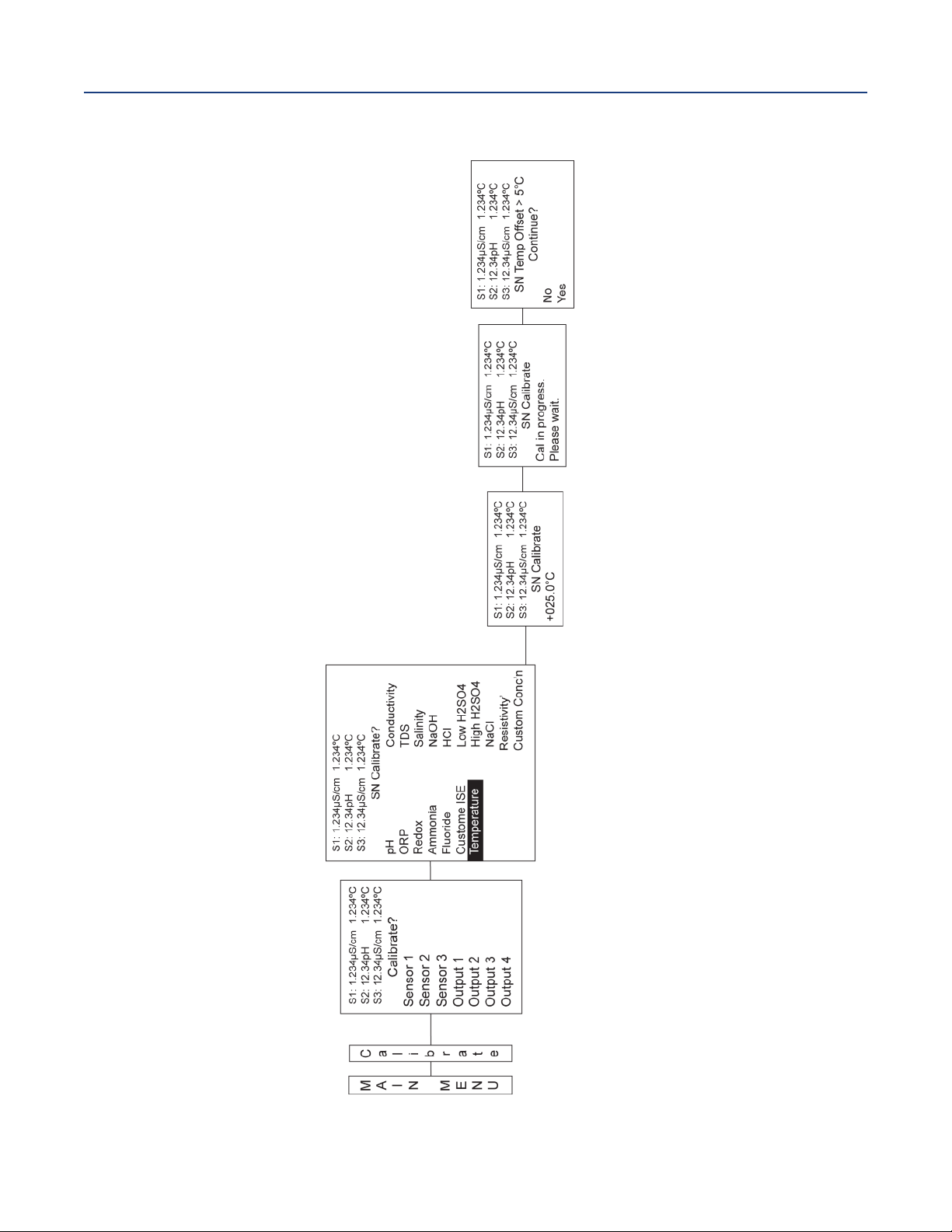
ection 7: Calibration
S
April 2017
Figure 7-4 Calibrate Temperature
nstruction Manual
I
LIQ-MAN-1057
Section 7: Calibration52
Page 63

nstruction Manual
I
LIQ-MAN-1057
Section 8: Return of Material
8.1 General
To expedite the repair and return of instruments, proper communication between the customer and
the factory is important. Before returning a product for repair, call 1-949-757-8500 for a Return
Materials Authorization (RMA) number.
8.2 Warranty Repair
The following is the procedure for returning instruments still under warranty:
1. Call Emerson for authorization.
2. To verify warranty, supply the factory sales order number or the original purchase order
number. In the case of individual parts or sub-assemblies, the serial number on the unit
must be supplied.
3. Carefully package the materials and enclose your “Letter of Transmittal” (see Warranty). If
possible, pack the materials in the same manner as they were received.
4. Send the package prepaid to:
Emerson
8200 Market Blvd.
Chanhassen, MN 55317
Attn: Factory Repair
RMA No. ____________
Mark the package: Returned for Repair
Model No. ____
ection 8: Return of Material
S
April 2017
IMPORTANT
Please see second section of “Return of
Materials Request” form. Compliance with
the OSHA requirements is mandatory for the
safety of all personnel. MSDS forms and a certification that the instruments have been disinfected or detoxified are required.
8.3 Non-Warranty Repair
The following is the procedure for returning for repair instruments that are no longer under warranty:
1. Call Emerson for authorization.
2. Supply the purchase order number, and make sure to provide the name and telephone
number of the individual to be contacted should additional information be needed.
3. Do Steps 3 and 4 of Section 8.2.
Note: Consult the factory for additional information regarding service or repair.
Section 8: Return of Material 53
Page 64

ection 8: Return of Material
S
April 2017
nstruction Manual
I
LIQ-MAN-1057
WARRANTY
Seller warrants that the firmware will execute the programming instructions provided by Seller, and that the Goods
manufactured or Services provided by Seller will be free from defects in materials or workmanship under normal use
nd care until the expiration of the applicable warranty period. Goods are warranted for twelve (12) months from the
a
date of initial installation or eighteen (18) months from the date of shipment by Seller, whichever period expires first.
Consumables, such as glass electrodes, membranes, liquid junctions, electrolyte, o-rings, catalytic beads, etc.,
and Services are warranted for a period of 90 days from the date of shipment or provision.
Products purchased by Seller from a third party for resale to Buyer ("Resale Products") shall carry only the warranty
extended by the original manufacturer. Buyer agrees that Seller has no liability for Resale Products beyond making a
reasonable commercial effort to arrange for procurement and shipping of the Resale Products.
If Buyer discovers any warranty defects and notifies Seller thereof in writing during the applicable warranty period,
Seller shall, at its option, promptly correct any errors that are found by Seller in the firmware or Services, or repair or
replace F.O.B. point of manufacture that portion of the Goods or firmware found by Seller to be defective, or refund
the purchase price of the defective portion of the Goods/Services.
All replacements or repairs necessitated by inadequate maintenance, normal wear and usage, unsuitable power
sources, unsuitable environmental conditions, accident, misuse, improper installation, modification, repair, storage
or handling, or any other cause not the fault of Seller are not covered by this limited warranty, and shall be at Buyer's
expense. Seller shall not be obligated to pay any costs or charges incurred by Buyer or any other party except as may
be agreed upon in writing in advance by an authorized Seller representative. All costs of dismantling, reinstallation
and freight and the time and expenses of Seller's personnel for site travel and diagnosis under this warranty clause
shall be borne by Buyer unless accepted in writing by Seller.
Goods repaired and parts replaced during the warranty period shall be in warranty for the remainder of the original
warranty period or ninety (90) days, whichever is longer. This limited warranty is the only warranty made by Seller
and can be amended only in a writing signed by an authorized representative of Seller. Except as otherwise expressly
provided in the Agreement, THERE ARE NO REPRESENTATIONS OR WARRANTIES OF ANY KIND, EXPRESS OR IMPLIED,
AS TO MERCHANTABILITY, FITNESS FOR PARTICULAR PURPOSE, OR ANY OTHER MATTER WITH RESPECT TO ANY OF
THE GOODS OR SERVICES.
RETURN OF MATERIAL
Material returned for repair, whether in or out of warranty, should be shipped prepaid to:
Emerson
8200 Market Blvd.
Chanhassen, MN 55317
The shipping container should be marked:
Return for Repair
Model _________________________________
The returned material should be accompanied by a letter of transmittal which should include the following information (make
a copy of the "Return of Materials Request" found on the last page of the Manual and provide the following thereon):
1. Location type of service, and length of time of service of the device.
2. Description of the faulty operation of the device and the circumstances of the failure.
3. Name and telephone number of the person to contact if there are questions about the returned material.
4. Statement as to whether warranty or non-warranty service is requested.
5. Complete shipping instructions for return of the material.
Adherence to these procedures will expedite handling of the returned material and will prevent unnecessary additional charges
for inspection and testing to determine the problem with the device.
If the material is returned for out-of-warranty repairs, a purchase order for repairs should be enclosed.
Section 8: Return of Material 54
Page 65
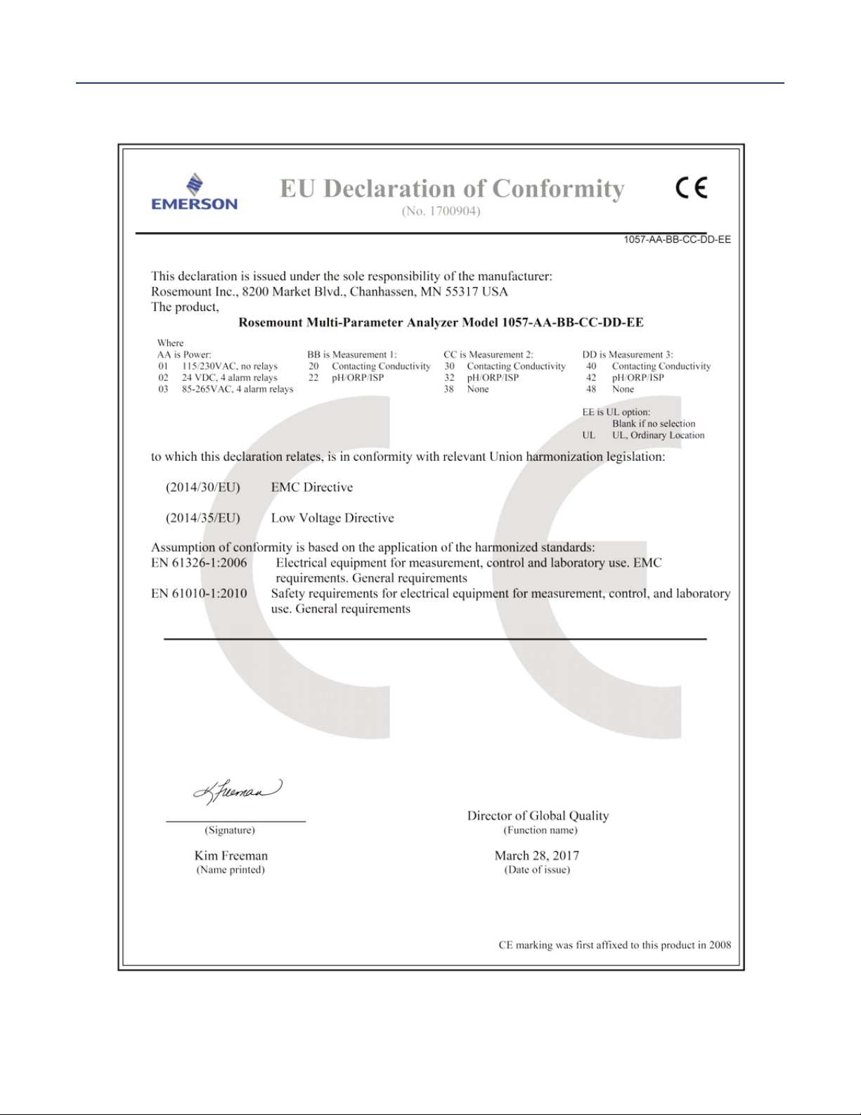
nstruction Manual
I
LIQ-MAN-1057
Note: Please see website for most recent Declaration.
C Declaration of Conformity
E
April 2017
EC Declaration of Conformity 55
Page 66

LIQ-MAN-1057
Rev. D
April 2017
www.Emerson.com/RosemountLiquidAnalysis
Youtube.com/user/Rosemount
Twitter.com/Rosemount_News
Emerson
8200 Market Blvd.
Chanhassen, MN 55317,
USA
Tel +1 800 999 9307
Fax +1 952 949 7001
Liquid.CSC@Emerson.com
Analyticexpert.com
facebook.com/Rosemount
©2017 Emerson. All rights reserved.
The Emerson logo is a trademark and service mark of Emerson Electric Co. Rosemount is a mark of
one of the Emerson family of companies. All other marks are the property of their respective
owners.
The contents of this publication are presented for information purposes only, and while effort has
been made to ensure their accuracy, they are not to be construed as warranties or guarantees,
express or implied, regarding the products or services described herein or their use or applicability.
All sales are governed by our terms and conditions, which are available on request. We reserve the
right to modify or improve the designs or specifications of our products at any time without notice.
 Loading...