

Page 1

Short Form Manual
HASAxE-SFM-HS
07/2006
Gas Analyzer Series
Short Form Manual
www.EmersonProcess.com
Page 2

ESSENTIAL INSTRUCTIONS
READ THIS PAGE BEFORE PROCEEDING!
Emerson Process Management (Rosemount Analytical) designs, manufactures and tests
its products to meet many national and international standards. Because these
instruments are sophisticated technical products, you MUST properly install, use, and
maintain them to ensure they continue to operate within their normal specifications. The
following instructions MUST be adhered to and integrated into your safety program when
installing, using and maintaining Emerson Process Management (Rosemount Analytical)
products. Failure to follow the proper instructions may cause any one of the following
situations to occur: Loss of life; personal injury; property damage; damage to this
instrument; and warranty invalidation.
• Read all instructions prior to installing, operating, and servicing the product.
• If you do not understand any of the instructions, contact your Emerson Process
Management (Rosemount Analytical) representative for clarification.
• Follow all warnings, cautions, and instructions marked on and supplied with the
product.
• Inform and educate your personnel in the proper installation, operation, and
maintenance of the product.
• Install your equipment as specified in the Installation Instructions of the
appropriate Instruction Manual and per applicable local and national codes.
Connect all products to the proper electrical and pressure sources.
• To ensure proper performance, use qualified personnel to install, operate, update,
program, and maintain the product.
• When replacement parts are required, ensure that qualified people use replacement
parts specified by Emerson Process Management (Rosemount Analytical).
Unauthorized parts and procedures can affect the product’s performance, place the
safe operation of your process at risk, and VOID YOUR WARRANTY. Look-alike
substitutions may result in fire, electrical hazards, or improper operation.
• Ensure that all equipment doors are closed and protective covers are in place,
except when maintenance is being performed by qualified persons, to prevent
electrical shock and personal injury.
The information contained in this document is subject to change without notice.
Edition 2006-07
Emerson Process Management GmbH & Co. OHG
Industriestrasse 1
D-63594 Hasselroth
Germany
T +49 (0) 6055 884-0
F +49 (0) 6055 884-209
Internet: www.EmersonProcess.com
Page 3

Short Form Manual
HASAxE-SFM-HS
05/2006
X-STREAM
PREAMBLE
This quick start guide provides BRIEF INFORMATION about X-STREAM series gas
analyzers concerning installation and operation. For more detailled information about these
topics as well as subassemblies, functions, procedures and maintenance refer to the related
sections of the X-STREAM gas analyzer instruction manual.
This guide covers several X-STREAM series analyzer variations and therefore may describe
configurations and/or options not part of your specific analyzer.
For more detailled safety instructions and precautions refer to the related sections of the
X-STREAM gas analyzer instruction manual.
DEFINITIONS
The following definitions apply to WARNINGS, CAUTIONS and NOTES found throughout
this publication.
Highlights an operation or maintenance procedure, practice, condition, statement, etc.
If not strictly observed, could result in injury, death, or long-term health
hazards of personnel.
Safety Instructions
Highlights an operation or maintenance procedure, practice, condition, statement, etc.
If not strictly observed, could result in damage to or destruction of equipment,
or loss of effectiveness.
NOTE!
Highlights an essential operating procedure, condition or statement.
Emerson Process Management GmbH & Co. OHG S-1
Page 4

Short Form Manual
X-STREAM
HASAxE-SFM-HS
05/2006
IMPORTANT
Safety Instructions
Wiring and Installation of this Apparatus
The following safety instructions apply specifically to all EU member states. They should be strictly
adhered to in order to assure compliance with the Low Voltage Directive. Non-EU st ates should also
comply with the following unless superseded by local or National Standards.
1. Adequate earth connections should be made to all earthing points, internal and external, where
provided.
2. After installation or troubleshooting, all safety covers and safety grounds must be replaced. The
integrity of all earth terminals must be maintained at all times.
3. To ensure safe operation of this equipment, connection to the mains supply should only be
made through a circuit breaker which will disconnect all circuits carrying conductors during a
fault situation. The circuit breaker may also include a mechanically operated isolating switch.
Circuit breakers or switches must comply with a recognized standard such as IEC947. All wiring
must conform with any local standards.
4. Where equipment or covers are marked with the symbol to the right, hazardous
voltages are likely to be present beneath. These covers should only be removed
when power is removed from the equipment — and then by trained service
personnel only .
5. Where equipment or covers are marked with the symbol to the right, there is a
danger from hot surfaces beneath. These covers should only be removed by
trained service personnel when power is removed from the equipment. Certain
surfaces may remain hot to the touch.
6. Where equipment or covers are marked with the symbol to the right, refer to the
Instruction Manual for instructions.
7. Further graphical symbols used in this product:
Electrostatic discharge (ESD)
Harmful (to Health)!
Explosion Hazard!
Toxic!
Heavy Instrument!
Disconnect from Mains!
All graphical symbols used in this product are from one or more of the following standards:
EN61010-1, IEC417, and ISO3864.
Emerson Process Management GmbH & Co. OHGS-2
Page 5

Short Form Manual
HASAxE-SFM-HS
05/2006
X-STREAM
Safety Instructions
Operating and Maintaining this Apparatus
This instrument has left the factory in compliance with all applicable safety regulations.
To maintain this operating condition, the user
must strictly follow the instructions and consider
the warnings in this manual or provided on the
instrument.
Before switching on the instrument, verify that
the electrical supply voltage matches the
instrument´s operating voltage as set in the
factory .
Any interruption in the instrument´s ground line,
whether inside or outside the instrument, or
removal or interruption of its ground line
connection, could result in hazardous operating
conditions. Intentionally interrupting the
instrument´s protective ground is strictly prohibited.
Opening cover panels could expose voltagecarrying components. Connectors may also be
under voltage. The instrument must be
disconnected from all electrical supplies before
attempting any calibrations, maintenance
operations, repairs or component
replacements requiring opening of the
instrument. Any calibrations, maintenance
operations, or repairs that need the instrument
to be opened while connected to electrical
supplies should be subject to qualified
technicians familiar with the hazards involved
only!
Observe all applicable regulations when
operating the instrument from an autotransformer or variac.
Substances hazardous to health may emerge
from the instrument‘s exhaust.
Please pay attention to the safety of your
operation personnel. Protective measures
must be taken, if required.
Safety Instructions
Use only fuses of the correct type and current
ratings as replacements. Using repaired fuses
and short circuiting of fuse holders is prohibited.
Emerson Process Management GmbH & Co. OHG S-3
Page 6

Short Form Manual
X-STREAM
Safety Instructions
HASAxE-SFM-HS
05/2006
INTENDED USE STATEMENT
X-Stream series gas analyzers are intended to be used as analyzers for industrial purposes.
They must not be used in medical, diagnostic or life support applications nor as safety
devices, and no independent agency certifications or approvals are to be implied as
covering such applications!
AUTHORIZED PERSONNEL
If this equipment is used in a manner not specified in these instructions, protective systems
may be impaired.
SAFETY SUMMARY
T o avoid loss of life, personal injury and damage to this equipment and on-site property , do
not operate or service this instrument before reading and understanding this quick start
guide.
The analyzer‘s instruction manual gives more detailled instructions. Save these documents.
ELECTRICAL SHOCK HAZARD !
Do not operate without covers secure. Do not open while energized.
Installation requires access to live parts which can cause death or serious
injury.
For safety and proper performace this instrument must be connected to a
properly grounded three-wire source of power.
TOXIC GASES !
This unit’s exhaust may contain toxic gases such as sulfur dioxide.
These gases can cause serious injuries.
Aviod inhalation of the exhaust gases at the exhaust fitting.
Connect exhaust outlet to a safe vent. Check vent line and connections for
leakage.
Keep all fittings tight to avoid leaks. See section 7-2, page 7-2 for leak test
instructions.
Emerson Process Management GmbH & Co. OHGS-4
Page 7

Short Form Manual
HASAxE-SFM-HS
05/2006
X-STREAM
Safety Instructions
EXPLOSION HAZARD !
Do not operate nor install these instruments in hazardous areas without additional measures!
HEAVY INSTRUMENTS !
The analyzer variation X-STREAM F, intended to be wall mounted and/or
outdoor installed, weighs up to approx. 26 kg (57 lbs), depending on
included options!
Use two people and/or suitable tools for transportation and lifting these
instruments!
Take care to use anchors and bolts specified to be used for the weight of
the units!
T ake care the wall or stand the unit is intended to be inst alled at is solid and
stable to hold the units!
Safety Instructions
HIGH TEMPERATURES !
While working with photometers and/or thermostated components inside
the analyzers hot components may be accessible!
Emerson Process Management GmbH & Co. OHG S-5
Page 8

X-STREAM
Magnetically Operated Front Panel
Magnetically Operated Front Panel
Persons with cardiac pacemakers should absolutely avoid magnetic
fields !
Negative effects on persons beyond those described above caused by
magnetic fields are not known. It is presumed that persons showing allergic
reaction on contact with ceramic or metallic material show the same
behavior on contact with magnetic material.
Short Form Manual
HASAxE-SFM-HS
05/2006
DANGER TO LIFE !
Permanent magnets are surrounded by magnetic fields. These magnetic
fields can disturb and even destroy sensitive electronic measuring devices,
but also mechanical watches, credit cards, etc.
Usually a distance of 20 inch (0.5 m) is enough to avoid damages. All sintered
permanent magnets are hard and brittle. Hitting of sintered permanent
magnets by the magnetic attraction causes splitting into fragments with many
sharp edges. This especially occurs with high energy magnets, and can
also cause skin bruises by high attraction.
High energy magnets made of rare-earth materials have to be stored dry,
otherwise the surfaces would oxidise. Unprotected operation in a humid
environment may cause corrosion. A void damaging the protective galvanic
coating.
A storage in a hydrogen atmosphere destroys these magnets. A
demagnetisation is caused when permanent magnet materials have been
exposed in a radioactive radiation for a long time.
For air transportation of magnetic material the IATA instructions have to be
observed:
Magnetic fields are not allowed to penetrate the package, if necessary the
magnets have to be shorted using a metal plate.
Emerson Process Management GmbH & Co. OHGS-6
Page 9

Short Form Manual
HASAxE-SFM-HS
05/2006
X-STREAM
TABLE OF CONTENTS
Preamble S-1
Definitions S-1
Safety Instructions S-2
Magnetically Operated Front Panel...................................................................................... S-6
Chapter 1 Installation 1-1
1-1 Abstract.......................................................................................................................1-1
1-2 Gas Conditioning .......................................................................................................1-2
1-3 Electrical Connections .............................................................................................. 1-5
1-4 Installation Instructions.............................................................................................1-6
1-4-1 X-STREAM GP, X-STREAM GPS...........................................................................1-6
1-4-1-1 Plugs & Sockets Version .................................................................................. 1-7
1-4-1-2 Terminals Version..............................................................................................1-9
1-4-2 X-STREAM F.........................................................................................................1-13
Chapter 2 Startup 2-1
2-1 Abstract.......................................................................................................................2-1
2-2 The User Interface......................................................................................................2-1
2-3 The Keys .....................................................................................................................2-2
2-4 Power-On Sequence .................................................................................................. 2-3
2-4-1 Measuring Screen .................................................................................................. 2-3
2-5 Menu structure ........................................................................................................... 2-4
2-6 Calibration ..................................................................................................................2-5
Table of Contents
Table of Figures
Fig. 1-0: Example of Gas Fittings Label ................................................................................................................1-3
Fig. 1-1: Bypass Mode Installation.........................................................................................................................1-5
Fig. 1-2: Frontal View .............................................................................................................................................1-6
Fig. 1-3: Rear Panel - Plugs & Sockets Version ....................................................................................................1-7
Fig. 1-4: Socket X1 - Pin Assignment ...................................................................................................................1-8
Fig. 1-5: IEC Mains Input Plug ...............................................................................................................................1-8
Fig. 1-6: Rear Panel - Terminals Version...............................................................................................................1-8
Fig. 1-7: Analog Signal Output Terminals ..........................................................................................................1-10
Fig. 1-8: Mains Terminals.....................................................................................................................................1-10
Fig. 1-9: X-STREAM F ..........................................................................................................................................1-12
Fig. 1-10: X-STREAM F -Allocation of Terminals and Gas Fittings .................................................................. 1-14
Fig. 1-11: X-STREAM F - Analog Output Terminals...........................................................................................1-16
Fig. 1-12: Mains Terminals...................................................................................................................................1-17
Fig. 2-1: X-STREAM User Interface........................................................................................................................2- 1
Fig. 2-2: X-STREAM Software Menu Structure ....................................................................................................2-4
Emerson Process Management GmbH & Co. OHG
T-1
Page 10

X-STREAM
Short Form Manual
HASAxE-SFM-HS
05/2006
Table of Contents
T-2
Emerson Process Management GmbH & Co. OHG
Page 11

Short Form Manual
HASAxE-SFM-HS
07/2006
X-STREAM
Chapter 1
Installation
This chapter describes in a brief manner how
to safely install the different analyzer models.
For more detailled instructions see the
X-STREAM instruction manual.
1-1 Abstract Carefully examine the shipping carton and contents for signs of damage.
Immediately notify the shipping carrier if the carton or its contents are damaged.
Retain the carton and packing material until the instrument is operational.
ELECTRICAL SHOCK HAZARD!
Prior to connecting the analyzer to mains ensure all safety instructions
as given in the appropriate chapters of this manualand the X-STREAM
instruction manual!
Installation area has to be clean, free from
moisture, excessive vibration and frostprotected. T ake care to meet the permissible
ambient temperatures as given in the technical data section!
Instruments must not be exposed to direct
sunlight nor sources of heat.
1 Installation
For outdoor installation it is recommended
to mount the instruments into a cabinet. At
least sheltering against rain is recommended.
1-1Emerson Process Management GmbH & Co. OHG
Page 12

X-STREAM
1-2 Gas Conditioning
Short Form Manual
HASAxE-SFM-HS
07/2006
1-1 Installation - Abstract
To ensure trouble-free analyzer operation
one has to attach great importance to gas
conditioning:
All gases must be conditioned
before supplying!
When supplying corrosive
gases ensure that gas path
components are not affected!
Flammable gases must not
supplied without additional
protective measures!
It is prohibited to supply explosive gases!
Furthermore the gases must be
- dry
- free of dust
- free of aggressive components affecting
gas path materials (e.g. by corrosion).
If moisture can not be avoided take care that
the gas‘ dew point is at least 18 F (10 °C) below
ambient temperature to avoid condensation
within the gas path.
Pressure and flow must be within the limits given
by the measurement specifications table 3-7
X-STREAM instruction manual, page 3-17).
(
1-2 Emerson Process Management GmbH & Co. OHG
Page 13

Short Form Manual
HASAxE-SFM-HS
07/2006
Take care that all external gas lines are connected as described and are
tight to avoid leaks!
Improperly connected gas lines may cause explosion or death!
Exhaust may contain hydrocarbon and other toxic components (e.g. carbon
monoxide)! Carbon monoxide is highly toxic and can cause headache,
nausea, loss of consciousness, and death. Avoid inhalation of exhaust!
X-STREAM
1-2 Installation - Gas Conditioning
TOXIC GAS HAZARDS!
Do not interchange gas inlet and outlet! All gases must be conditioned before
supplying! When supplying corrosive gases ensure that gas path components
are not affected!
Max. permissible gas pressure: 21.7 psi (1,500 hPa), except instruments with
integrated valve blocks (7.25 psi; 500 hPa) and/or paramagnetic oxygen sensor
table 3-7, page 3-17)!
(
Exhaust lines must be installed in a descending way, need to be pressureless,
frost-protected and in compliance with applicable legislative requirements!
The number of gas fittings as well as their
assignment vary depending on analyzer model
and selected options.
All gas fittings are labeled and are located at
• the analyzer's rear panel (X-STREAM GP ,
X-STREAM GPS)
• the analyzer's bottom side (X-STREAM F)
When it is necessary to open gas paths seal
the analyzer‘s gas fittings using PVC caps to
Fig. 1-0: Example of Gas Fittings Label
avoid pollution of the internal gas path by
moisture, dust, etc.
1 Installation
1-3Emerson Process Management GmbH & Co. OHG
Page 14
X-STREAM
Short Form Manual
HASAxE-SFM-HS
07/2006
1-2 Installation - Gas Conditioning
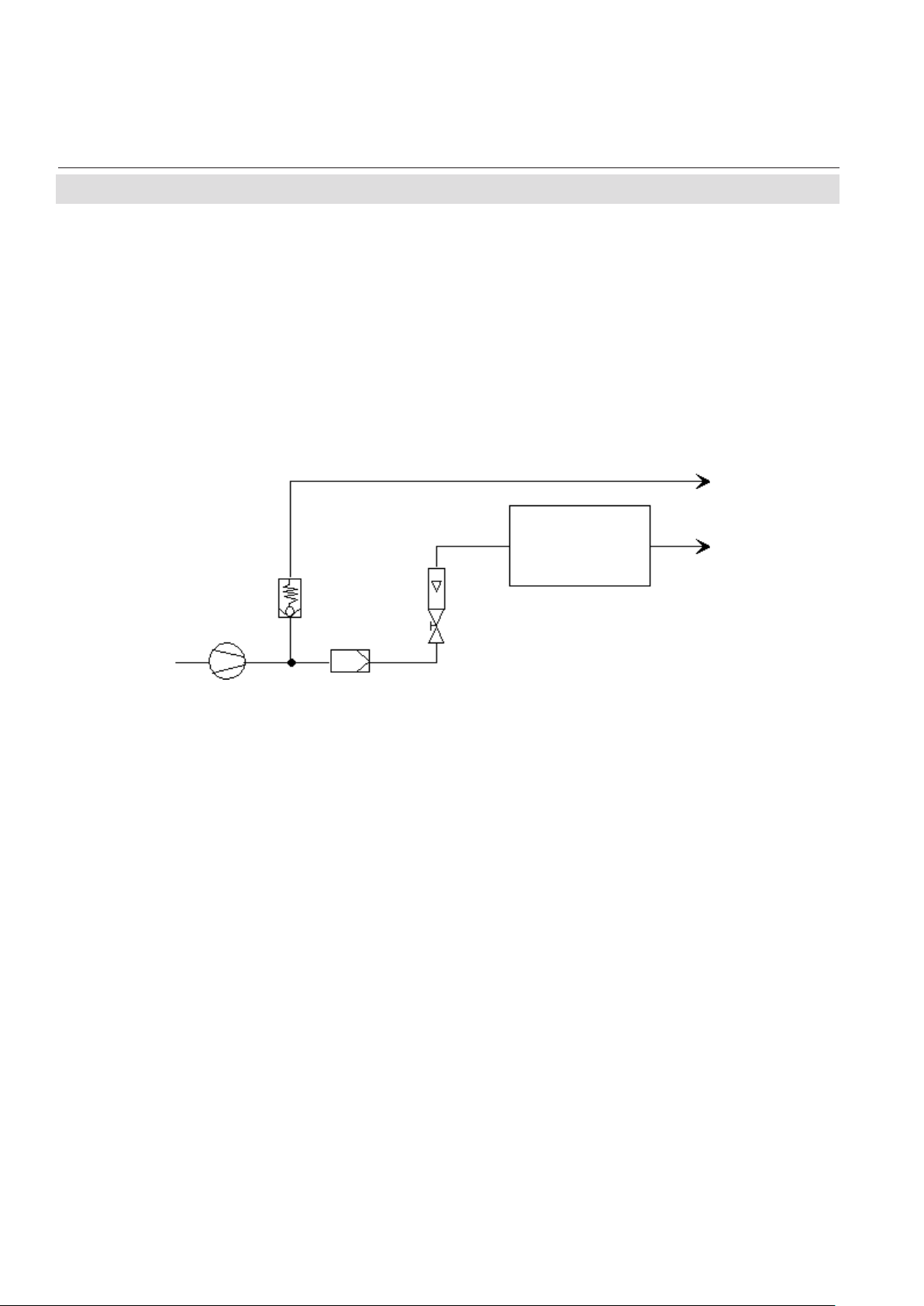
The analyzer should be mounted near the
sample source to minimize sample transport
time. A sample pump may be used to decrease
response time, whereat the analyzer is either
Overpressure valve
Filter
Sample pump
Fig. 1-1: Bypass Mode Installation
operated in bypass mode or protected by an
overpressure valve against too high flow and
pressure (fig. 1-1).
Output
Analyzer
Flowmeter
Output
Internal Solenoid Valve Block
Supply overpressure for all gases is limited to
0.7 to 7.2 psi (50 to 500 hPa) when the analyzer
is equipped with an internal solenoid valve
block.
1-4 Emerson Process Management GmbH & Co. OHG
Page 15

Short Form Manual
HASAxE-SFM-HS
07/2006
1-3 Installation - Electrical Connections
1-3 Electrical Connections
Installation and connecting mains and signal cables are subject to qualified
personnel only taking into account all applicable standards and legislative
requirements! V erify the mains volt age at site of inst allation corresponds to
the analyzer´s rated voltage as given on the nameplate label!
Failure to follow may cause warranty invalidation, property damage and/or
personal injury or death!
Installation of these instruments is subject to qualified personnel only,
familiar with the resulting potential risks! Instruments providing screw
terminals for electrical connections may require working near live part!
X-STREAM
ELECTRICAL SHOCK HAZARD!
X-STREAM gas analyzers do not provide a mains switch!
For X-STREAM F analyzers a mains switch or circuit breaker (complying
with IEC 60947-1/-3) has to be provided in the building installation. This switch
has to be installed near by analyzer , must be easily operator accessible and
has to be assigned as disconnector for the analyzer.
Disconnect instruments with screw terminals from mains when working at
mains terminals (pull mains plug or operate mains switch/ circuit breaker in
building installation)!
The analyzers provide a protective earth terminal. T o prevent electrical shock
hazards the instruments must be connected to a protective earth. Therefore
the instruments must be connected to mains by using a three wire mains
cable with earth conductor!
Any interruption of the earth connector inside or outside the instrument or
disconnecting the earth terminal may cause potential electrical shock
hazzard!
The analyzers do not provide a mains switch and are operable when connected to power.
Installation instructions for
1 Installation
X-STREAM GP, X-STREAM GPS Page 1-6
X-STREAM F Page 1-13
1-5Emerson Process Management GmbH & Co. OHG
Page 16

X-STREAM
1-4-1 Installation - X-STREAM GP, X-STREAM GPS
1-4 Installation Instructions 1-4-1 X-STREAM GP, X-STREAM GPS
Short Form Manual
HASAxE-SFM-HS
07/2006
The analyzer variations X-STREAM GP and
GPS are intended for horizontal orientation
during operation.
X-STREAM GP / GPS with mounting frames
beside the front panel may be mounted into a
rack (rack mount version). Use four screws to
fix the analyzer in the rack (fig. 1-2).
Depending on which variation was ordered
either screw terminals or plugs and sockets are
provided for electrical connections, accessible
at the rear panel (fig. 1-3 and 1-6).
The analyzers do not provide a
power switch and are operable
when connected to power.
Fixing holes for rack mounting (rack mount version only)
(0.3 x 0.4 inches / 7.5 x 10.5 mm)
Fig. 1-2:Frontal view
1-6 Emerson Process Management GmbH & Co. OHG
Page 17

Short Form Manual
HASAxE-SFM-HS
07/2006
1-4-1 Installation - X-STREAM GP, X-STREAM GPS
1-4-1-1 Plugs & Sockets Version
1
2
Gas inlets
Gas outlets
X-STREAM
Modbus interface
Analog outputs
Digital inputs /
Relays
outputs
3
4
(option)
Mains fuses
Purge gas inlet
Fig. 1-3: Rear panel - plugs & sockets version (GPS)
Mains appliance
The number and assignment of gas inlet and outlet fittings depends on the application and is given
on a label attached to the analyzer's rear panel adjacent to the fittings.
For simple installation we recommend to mark the gas lines according to fig. 1-3 (In1, Out1, In2,
Out2, ...). This avoids confusion during rae-installation when the analyzer had to be disconnected for
whatever reason.
Gas inlets and outlets
Quantity: max. 8 (+ 1 optional purge gas fitting)
Specification: 6/4 mm PVDF
optional 6/4 mm or 1/4", stainles steel,
other on request
1 Installation
1-7Emerson Process Management GmbH & Co. OHG
Page 18

X-STREAM
1-4-1 Installation - X-STREAM GP, X-STREAM GPS
Preparing the analog output signal cable
The signal cable is to be connected via a
submin-d connector at the analyzer's rear panel:
Short Form Manual
HASAxE-SFM-HS
07/2006
1 / not used
2 / not used
3 / (+) 4 (0) - 20 mA, channel 1
4 / not used
5 / (+) 4 (0) - 20 mA, channel 2
Burden: RB ≤ 500 Ω
Legend: Pin # / Signal
Fig. 1-4: Socket X1 - pin assignment
Note!
For information on how to connect other signal
cables check the related section of the
X-STREAM instruction manual!
Preparation of mains cable
6 / not used
7 / (-) 4 (0) - 20 mA channel 1
8 / not used
9 / (-) 4 (0) - 20 mA channel 2
The mains power inlet appliance is of type IEC.
Use a standard mains cable with IEC connector
complying with your local requirements to
supply the instrument with power.
Fig. 1-5: IEC mains input plug
1-8 Emerson Process Management GmbH & Co. OHG
Protective
Earth (PE)
Page 19

Short Form Manual
HASAxE-SFM-HS
07/2006
1-4-1 Installation - X-STREAM GP, X-STREAM GPS
1-4-1-2 Terminals Version
Gas inlets
Gas outlets
1
2
3
4
Strain-reliefs
Edge protection
}
X-STREAM
Analog outputs / relays /
Digital inputs / outputs
Modbus interface
Mains fuse
Mains
terminals
Mains fuse
Cover
(illustrated transparent)
Fig. 1-6: Rear panel - terminals version (GP)
4 screws for
fixing the cover
The number and assignment of gas inlet and outlet fittings depends on the application and is given
on a label attached to the analyzer's rear panel adjacent to the fittings.
For simple installation we recommend to mark the gas lines according to fig. 1-3 (In1, Out1, In2,
Out2, ...). This avoids confusion during re-installation when the analyzer had to be disconnected for
whatever reason.
A label fixed to the inner side of the terminals cover shows how the terminals are assigned.
Gas inlets and outlets
Quantity: max. 8 (+ 1 optional purge gas fitting)
Specification: 6/4 mm PVDF
optional 6/4 mm or 1/4", stainles steel,
other on request
1 Installation
1-9Emerson Process Management GmbH & Co. OHG
Page 20

X-STREAM
1-4-1 Installation - X-STREAM GP, X-STREAM GPS
Connecting the analog output signal cable
Short Form Manual
HASAxE-SFM-HS
07/2006
The signal cable is to be connected via screw
terminals, located at the analyzer's rear panel.
to the cable shield after the cable's outer
insulation is stripped.
The strain reliefs provide a metal strip to connect
Maximum outer cable diameter: 0.6 inch (15 mm)
Supported wire cross sections: 24 to 14 A WG (0.2 to 2.5 mm
no need to use wire end sleeves
Cable skinning length: 0.354 inch (9 mm)
Screw thread: M 2.5
Tightening torque, min: 3.5 in.lb (0.4 Nm)
To connect the terminals remove the cover at
the analyzer's rear panel (4 screws). Feed the
analog signals cable through the uppermost
edge protection, and through the upper strainrelief.
The upper 4 terminals (# 1 - 4) of the terminals
row next to the mains terminals are reserved
for analog signal outputs.
Note!
For information on how to connect other signal
cables check the related section of the
X-STREAM instruction manual!
2
),
(+) 4 (0) - 20 mA, channel 1
(-) 4 (0) - 20 mA, channel 1
(+) 4 (0) - 20 mA, channel 2
(-) 4 (0) - 20 mA, channel 2
Burden: RB ≤ 500 Ω
Fig. 1-7: Analog Signal Output Terminals
1-10 Emerson Process Management GmbH & Co. OHG
Page 21

Short Form Manual
HASAxE-SFM-HS
07/2006
1-4-1 Installation - X-STREAM GP, X-STREAM GPS
Connecting the mains cable
The mains cable is connected by screw terminals, located at the analyzer's rear panel.
Use a mains cable with plug for wall outlet socket.
ELECTRICAL SHOCK HAZARD!
Verify cables are disconnected from mains
prior to working at the mains terminals!
Maximum outer cable diameter: 0.6 inch (15 mm)
X-STREAM
Supported wire cross sections: 24 to 14 A WG (0.2 to 2.5 mm2),
no need to use wire end sleeves
Cable skinning length: 0.354 inch (9 mm)
Screw thread: M 2.5
Tightening torque, min: 3.5 in.lb (0.4 Nm)
To connect the terminals remove the cover at
the analyzer's rear panel (4 screws). Feed the
The 3 rightmost terminals (between the fuse
holders) are reserved for mains.
mains cable through the lower edge protection,
through the lower strain-relief and around the
separation between mains terminals and next
terminals row.
Line (L)
Protective
Earth (PE)
Neutral (N)
1 Installation
Fig. 1-8: Mains terminals
1-11Emerson Process Management GmbH & Co. OHG
Page 22

X-STREAM
Short Form Manual
HASAxE-SFM-HS
07/2006
1-4-1 Installation - X-STREAM GP, X-STREAM GPS
ELECTRICAL SHOCK HAZARD!
Before completing the electrical
connection of the instrumen verify
screws are tight and cables are
inserted correctly!
Ensure the earthing conductor is
connected!
After all connections are established in correct
manner and verified,
• place the edge protection rubbers into the
associated openings of the cover
and finally
• attach the terminals cover to the instrument's rear panel utilizing all 4 torx screws.
1-12 Emerson Process Management GmbH & Co. OHG
Page 23

Short Form Manual
HASAxE-SFM-HS
07/2006
1-4-2 Installation - X-STREAM F
1-4-2 X-STREAM F
The X-STREAM F analyzer variation is
intended for outdoor installation and wall
mounting, utilizing 4 supports:
X-STREAM
4 supports for bolts with
diameters 6 mm / 0.23 inch
Eyebolts detail
509 [20]
sash fasteners (2 pcs)
330 [13]
Dimensions: mm [inch]
Fig. 1-9: X-STREAM F
1 Installation
HEAVY INSTRUMENTS !
The analyzer variation X-STREAM F , intended to be wall mounted and/or
outdoor installed, weighs up to approx. 26 kg / 57 lbs), depending on
included options!
Use two people and/or suitable tools for transportation and lifting these
instruments!
Take care to use anchors and bolts specified to be used for the weight of
the units!
T ake care the wall or stand the unit is intended to be inst alled at is solid and
stable to hold the units!
1-13Emerson Process Management GmbH & Co. OHG
Page 24

X-STREAM
Short Form Manual
HASAxE-SFM-HS
07/2006
1-4-2 Installation - X-STREAM F
The instrument provides internal screw terminals for connecting mains and electrical signal
cables. This requires opening the instrument
during installation utilizing the sash fasteners.
Gas fittings are accessible at the instrument‘s
outer bottom side.
The number and assignment of gas inlet and
outlet fittings depends on the application and
is given on a label attached to the analyzer's
bottom side adjacent to the fittings.
For simple installation we recommend to mark
the gas lines according to the marking. This
avoids confusion during re-installation when the
analyzer had to be disconnected for whatever
reason.
1
4
1423
1 T erminals for signal cables
2 Mains EMI filter
3 4 cable glands for mains and signal cables
4 Mains terminals with integrated fuses
Fig. 1-10: X-STREAM F -Allocation of terminals and gas fittings
7
5 Cable glands for mains and signal cables
6 Gas inlet and outlet fittings
7 Purge gas inlet fitting (option)
6
Gas inlets
Gas outlets
5
Gas inlets and outlets
Quantity: max. 8 (+ 1 optional purge gas fitting)
Specification: 6/4 mm PVDF
optional 6/4 mm or 1/4", stainles steel;other on request
1-14 Emerson Process Management GmbH & Co. OHG
Page 25

Short Form Manual
HASAxE-SFM-HS
07/2006
1-4-2 Installation - X-STREAM F
ELECTRICAL SHOCK HAZARD!
V erify mains cables are disconnected and/or instrument is de-energized prior
to working at the terminals!
Preparation of signal cables
All signal cables are to be connected via screw
terminals, located inside the analyzer. The
instruments inner components are accessible
X-STREAM
after loosening the two fasteners at it‘s upper
end and opening the front door downwards.
Supported outer cable diameter: 0.27 to 0.47 inch (7 to 12 mm)
Supported wire cross sections: 24 to 14 A WG (0.2 to 2.5 mm
no need to use wire end sleeves
Cable skinning length: 0.354 inch (9 mm)
Screw thread: M 2.5
Tightening torque, min: 3.5 in.lb (0.4 Nm)
All cables need to be fed through cable glands
when entering the instrument and fixed by the
gland nut when connected to the terminals.
The cable glands provide strain-relief and
protection against EMI (Electro Magnetic
Interference) when installed in a proper way:
Cable Gland Assembly Instruction for Shielded Cables
1. Strip the cable
insulation
2. Uncover the shielding
5. Stick the fixing element
into the neck and fix the
gland.
3. Feed cable through
gland nut and into fixing
element
2
),
1 Installation
4. Put the shielding net
over the element the
way that it covers the
o-ring 2 mm.
1-15Emerson Process Management GmbH & Co. OHG
Page 26

X-STREAM
1-4-2 Installation - X-STREAM F
Connecting the analog output signal cable
For access to the terminals open the instrument's front door.
Insert the cable into the housing utilizing one of
the three rear cable glands. Strip the outer
insulation, skin and connect the conductors to
the terminals (a descriptive label is fixed nearby
the terminals).
When done, fix the cable by tightening the outer
cable gland nut.
Short Form Manual
HASAxE-SFM-HS
07/2006
Note!
For information on how to connect other signal
cables check the related section of the
X-STREAM instruction manual!
The rightmost 4 terminals (# 1 - 4) of the
terminals row next to the mains terminals are
reserved for analog signal outputs.
Burden: RB ≤ 500 Ω
(-) 4 (0) - 20 mA, channel 2
(+) 4 (0) - 20 mA, channel 2
(-) 4 (0) - 20 mA, channel 1
(+) 4 (0) - 20 mA, channel 1
Fig. 1-11: X-STREAM F - Analog output terminals
1-16 Emerson Process Management GmbH & Co. OHG
Page 27

Short Form Manual
HASAxE-SFM-HS
07/2006
X-STREAM
1-4-2 Installation - X-STREAM F
Connecting the mains cable
The mains cable is connected by screw
terminals, located inside analyzer.
Supported outer cable diameter: 0.27 to 0.47 inch (7 to 12 mm)
Supported wire cross sections: 24 to 12 A WG (0.2 to 4 mm2),
no need to use wire end sleeves
Cable skinning length: 0.315 inch (8 mm)
Screw thread: M 3
Tightening torque, min: 4.4 in.lb (0.5 Nm)
ELECTRICAL SHOCK HAZARD!
V erify mains cables are disconnected and/or instrument is de-energized prior
to working at the terminals!
Verify the mains cable has a distance of at least 1 cm (0.5“) to any signal
cable to ensure proper insulation from signal circuits!
Insert the mains cable through the foremost
cable gland, strip the outer insulation, skin and
connect the conductors to the terminals (a
descriptive label is fixed to the filter‘s housing
nearby the terminals).
When done, fix the mains cable by tightening
the outer cable gland nut.
L=Line
N=Neutral
PE=Protective Earth
for label
PE
N
Fig. 1-12: Mains terminals
Mains cable glandLocation
L
1 Installation
1-17Emerson Process Management GmbH & Co. OHG
Page 28

X-STREAM
Before completing the electrical connection of the instrument verify cables
are inserted correctly!
Ensure the earthing conductor is connected!
Short Form Manual
HASAxE-SFM-HS
07/2006
1-4-2 Installation - X-STREAM F
ELECTRICAL SHOCK HAZARD!
After all connections are established in correct
manner and verified,
• close the front door and secure it utilizing
the two sash fasteners.
1-18 Emerson Process Management GmbH & Co. OHG
Page 29

Short Form Manual
HASAxE-SFM-HS
05/2006
Chapter 2
2-1 Abstract
Once the analyzer has been istalled successfully just ensure all gases are applied and power on the instrument to operate it.
2-2 The User Interface
The X-STREAM gas analyzer‘s user interface
consists of a 4x20 character alphanumeric LC
display (fieldhousing:optional VF display),
providing all the necessary information to
operate, calibrate and function check the
instrument.
X-STREAM
Startup
The underlying software is operated by six keys.
Additional status information is provided utilizing three LEDs right below the display .
In case of X-STREAM F the display, LEDs and
keys are located behind a protective glass and
the keys (sensors) are operated by a magnetic
tool.
12345678
1 Display
2 Failure LED
3 Maintenance / Check requests / Off spec LED
4 Power LED
Fig. 2-1: X-STREAM user interface
Emerson Process Management GmbH & Co. OHG 2-1
5 HOME key
6 UP / DOWN keys
7 ENTER key
8 LEFT / RIGHT keys
2 Startup
Page 30

X-STREAM
2-3 The Keys
Short Form Manual
HASAxE-SFM-HS
05/2006
2-3 The Keys
Six keys are provided to operate the menu
system. Depending on the three operation
modes (measure-browse-edit) they have the
following functionality:
ENTER key:
Mode Function
Measure Exit measuring screen
Browse Select menu (..) or function (!)
Edit Submit new input
HOME key:
Mode Function
Measure (without function)
Browse Return to measuring screen
Edit Abort editing
UP / DOWN keys:
Mode Function
Measure Exit measuring screen
Browse - Select a menu line
- Open previous/next menu page if
placed in a line starting with /
Edit increase /decrease the input value
LEFT key:
Mode Function
Measure Exit measuring screen
Browse One page/level back in menu tree
Edit - Shift cursor on the input field
- Leave Component Selection
menu
- Abort editing an enumerated
variable
RIGHT key:
Mode Function
Measure Exit measuring screen
Browse - Enter submenu in lines ending ..
- show next menu page for menu
pages with in the 4th line
Edit Shift cursor on the input field
Emerson Process Management GmbH & Co. OHG2-2
Page 31

Short Form Manual
HASAxE-SFM-HS
05/2006
2-4 Power-On Sequence
2-4 Power-On Sequence
After Power-On a sequence of start-up messages is displayed. During this time all keys are
disabled. The sequence takes a few seconds
(a counter shows the remaining time) until the
measuring screen shows up.
2-4-1 Measuring Screen
X-STREAM
The measuring screen shows up
• automatically after the start-up sequence
has finished
• when pressing the HOME key
• when a programmable time has elapsed
without user interaction (without pressing
a key).
The information shown on the upper three lines
is (within limits) user configurable and by default
are setup to as follows:
• The upper line shows the channel 1 data.
• For dual channel instruments the second
line gives the data for the second
measuring channel.
• The 3rd line may show an additional
parameter (e.g. internal temperature).
• The 4th line is used for cleartext status infor-
mation like failures, calibration events etc.
Messages are stored in an internal
message buffer and then put onto the line.
If there is more than one message in the
buffer the content of the message line will
change every 1-2 seconds.
Any failure, maintenance, function check or outof-spec message appearing in this line
activates the related front panel LED and the
NAMUR relay , too.
CO2.1 135.1 ppm
O2.2 201952 ppm
Temp-1 58.8 °C
(Messages)
MEASURING SCREEN
Refer to fig. 2-2 for an overview about the
software menu structure.
2 Startup
Emerson Process Management GmbH & Co. OHG 2-3
Page 32

X-STREAM
2-5 Menu structure
Short Form Manual
HASAxE-SFM-HS
05/2006
2-5 Menu Structure
Fig. 2-2: X-STREAM Software menu structure
Emerson Process Management GmbH & Co. OHG2-4
Page 33

Short Form Manual
HASAxE-SFM-HS
05/2006
2-6 Set User Interface Language
2-6 Set User Interface Language
X-STREAM
Sequence of keys to be entered for changing the language of an analyzer, if the
operator is not competent in the currently
setup language
(Sequence starting from the measuring screen)
Note!
After pressing the ENTER key the 4th time
within this sequence you entered the
LANGUAGE parameter line.
The DOWN key changes the language. A f ter
pressing the ENTER key this language is
set and the menu's language is updated
immediately.
If the selected language is not the one desired,
repeat the sequence of last three keys multiple
times until the desired language is set.
Emerson Process Management GmbH & Co. OHG 2-5
2 Startup
Page 34

X-STREAM
2-7 Calibration
Short Form Manual
HASAxE-SFM-HS
05/2006
2-7 Calibration
To achieve valid measuring results it is
recommended to perform a calibration. This
section describes in short form how to perform
a manual calibration procedure.
Setup..
Calibration..
Calibration gases..
Calibration gases
ZeroGas: 0.0 ppm
SpanGas: 500.0 ppm
For more detailled information about calibration
and available calibration procedures refer to
the X-STREAM instruction manual.
Within the measuring screen press the DOWN
key and then enter the CALIBRATION setup
menu for specifying the calibration gas
concentrations.
Within this screen enter the values for the listed
gases: Take the correct values from your gas
supplier's certificate. Proper values only assure
faultless measuring results.
For multichannel instruments enter the values
for each channel separately .
Zero calibration..
Span calibration..
Next enter the CONTROL menu to start a zero
calibration.
Make sure the required calibration gas is applied and flowing!
Supply all calibration gases with
the same flow as the sample gas
(recommeded approx. 1 l/min),
pressureless and utilizing the
right gas fitting.
Ensure the warm-up time after
switching on has elapsed!
Warm-up time is 15 to 50 minutes
depending on installed measuring system and configuration!
Emerson Process Management GmbH & Co. OHG2-6
Page 35

Short Form Manual
HASAxE-SFM-HS
05/2006
X-STREAM
2-7 Calibration
CANCEL calibration!
START calibration!
ZeroGas 0.000 ppm
CO2.1 0.200 ppm
CANCEL calibration!
START calibration!
SpanGas 20.000 ppm
CO2.1 16.200 ppm
Select the second line to start the calibration.
Line 3 shows the calibration gas setup (here:
required zero gas concentration is 0.000 ppm),
while line 4 shows the currently measured gas
concentration.
When finished press the LEFT key two times
to return to the controls menu, which allows you
to start a span calibration. The procedure and
screens look similiar to those of a zero
calibration:
Before selecting any further line
make sure the required calibration gas is applied and flowing!
Select the second line to start the calibration.
Line 3 shows the calibration gas setup (here:
required span gas concentration is 20 ppm),
while line 4 shows the currently measured gas
concentration.
When finished press the HOME key to return
to the measurement screen to finish the manual
calibration procedures.
Emerson Process Management GmbH & Co. OHG 2-7
2 Startup
Page 36

X-STREAM
Short Form Manual
HASAxE-SFM-HS
05/2006
Emerson Process Management GmbH & Co. OHG2-8
Page 37

Short Form Manual
HASAxE-SFM-HS
05/2006
X-STREAM
Page 38

X-STREAM
EUROPE
Emerson Process Management GmbH & Co. OHG
Industriestrasse 1
63594 Hasselroth
Germany
T +49 (6055) 884-0
F +49 (6055) 884-209
Internet: www.emersonprocess.de
EUROPE, MIDDLE EAST , AFRICA
Emerson Process Management Shared Services Limited
Heath Place
Bognor Regis
West Sussex PO22 9SH
England
T +44-1243-863121
F +44-1243-845354
Internet: www.emersonprocess.co.uk
Short Form Manual
HASAxE-SFM-HS
05/2006
NORTH AMERICA
Emerson Process Management
Rosemount Analytical Inc.
6565P Davis Industrial Parkway
Solon, OH 44139-3922
USA
T +1 (440) 914-1261
F +1 (440) 914-1271
Internet: www.emersonprocess.com
LATIN AMERICA
Emerson Process Management
Rosemount Analytical Inc.
Latin America Headquarters
11100 Brittmoore Park Drive
Houston, TX 77041
USA
T +1 (713) 467-6000
F +1 (713) 827-3329
ASIA - P ACIFIC
Emerson Process Management Asia Pacific Pte Ltd
1 Pandan Crescent
Singapore 128461
T +65 6777 8211
F +65 6777 0947
Internet: www.ap.emersonprocess.com
© 2006 Emerson Process Management GmbH & Co. OHG
 Loading...