

X-STREAM X1 Flameproof Addendum for Hazardous Area Applications-3rd Ed.
Table of contents
 Loading...
Rosemount X-STREAM X1 Flameproof Addendum for Hazardous Area Applications-3rd Ed. Manuals & Guides
Page 1

Instruction Manual
HASADE-IM-Ex
07/2007
Flameproof Gas Analyzer
Instruction Manual Addendum for
Hazardous Area Applications
www.EmersonProcess.com
Page 2

ESSENTIAL INSTRUCTIONS
READ THIS PAGE BEFORE PROCEEDING!
Emerson Process Management (Rosemount Analytical) designs, manufactures and
tests its products to meet many national and international standards. Because these
instruments are sophisticated technical products, you MUST properly install, use, and
maintain them to ensure they continue to operate within their normal speci.cations.
The following instructions MUST be adhered to and integrated into your safety program
when installing, using and maintaining Emerson Process Management (Rosemount
Analytical) products. Failure to follow the proper instructions may cause any one of the
following situations to occur: Loss of life; personal injury; property damage; damage to
this instrument; and warranty invalidation.
• Read all instructions prior to installing, operating, and servicing the product.
• If you do not understand any of the instructions, contact your Emerson Process
Management (Rosemount Analytical) representative for clarication.
• Follow all warnings, cautions, and instructions marked on and supplied with the
product.
• Inform and educate your personnel in the proper installation, operation, and
maintenance of the product.
• Install your equipment as speci.ed in the Installation Instructions of the
appropriate Instruction Manual and per applicable local and national codes.
Connect all products to the proper electrical and pressure sources.
• To ensure proper performance, use qualied personnel to install, operate, update,
program, and maintain the product.
• When replacement parts are required, ensure that qualied people use replacement
parts specied by Emerson Process Management (Rosemount Analytical).
Unauthorized parts and procedures can affect the product’s performance, place the
safe operation of your process at risk, and VOID YOUR WARRANTY. Look-alike
substitutions may result in re, electrical hazards, or improper operation.
• Ensure that all equipment doors are closed and protective covers are in place,
except when maintenance is being performed by qualied persons, to prevent
electrical shock and personal injury.
The information contained in this document is subject to change without notice.
3rd edition 2007-07
2nd edition 2007-04
1st edition 2006-07
Emerson Process Management GmbH & Co. OHG
Industriestrasse 1
D-63594 Hasselroth
Germany
T +49 (0) 6055 884-0
F +49 (0) 6055 884-209
Internet: www.EmersonProcess.com
Page 3

Instruction Manual
HASDE-IM-Ex
04/2007
X-STREAM FD
PREAMBLE
This instruction manual provides information about installing, operating and maintaining/
servicing X-STREAM series gas analyzers in hazardous (classied) areas and shall be read
in conjunction with the standard analyzer instruction manual only!
This instruction manual covers several X-STREAM series analyzer variations and therefore
may describe congurations and/or options not part of your specic analyzer.
DEFINITIONS
The following denitions apply to WARNINGS, CAUTIONS and NOTES found throughout
this publication.
Highlights an operation or maintenance procedure, practice, condition,
statement, etc.
If not strictly observed, could result in injury, death, or long-term health
hazards of personnel.
Highlights an operation or maintenance procedure, practice, condition,
statement, etc.
Safety Instructions
If not strictly observed, could result in damage to or destruction of equipment,
or loss of effectiveness.
NOTE
Highlights an essential operating procedure, condition or statement.
Emerson Process Management GmbH & Co. OHG S-1
Page 4

Instruction Manual
HASDE-IM-Ex
04/2007
Emerson Process Management GmbH & Co. OHGS-2
X-STREAM FD
Symbols
SYMBOLS USED IN THIS MANUAL
1. Where equipment or covers are marked with the symbol to the right, hazardous voltages are likely to be present beneath. These covers should only be
removed when power is removed from the equipment — and then by trained
service personnel only.
2. Where equipment or covers are marked with the symbol to the right, there is a
danger from hot surfaces beneath. These covers should only be removed by
trained service personnel when power is removed from the equipment. Certain
surfaces may remain hot to the touch.
3. Where equipment or covers are marked with the symbol to the right, refer to
the Instruction Manual for instructions.
4. Further graphical symbols possibly used in this product:
Elektrostatic discharge (ESD)
Harmful (to Health)!
Explosion Hazard!
Toxic!
Heavy Instrument!
Disconnect from Power!
Page 5

Instruction Manual
HASDE-IM-Ex
04/2007
TERMS USED IN THIS MANUAL
ATEX
Directive 94/9/EC, commonly called the
ATEX („Atmosphères Explosibles“) directive,
dealing with equipment intended to be used
in potentially explosive atmospheres.
This directive is valid for equipment to be
sold into and/or installed and operated in the
European Union (EU).
Area Classication
X-STREAM FD
Terms
Safety Instructions
Zone 1
Where ignitable concentrations of ammable
gases can exist some of the time under normal operating conditions.
(A guideline value [not part of a standard ] is
10 to 1.000 hours per year.)
Flammable Gas(es)
Gases and gas mixtures are assigned to be
ammable if they might become ignitable
when in a mixture with air.
Lower Explosion Limit (LEL)
Volume ratio of ammable gas in air below
which an explosive gas atmosphere will not
be formed: the mixture of gas and air lacks
sufcient fuel (gas) to burn.
Zone 2
Where ignitable concentrations of ammable
gases are not likely to exist under normal
operating conditions.
(A guideline value [not part of a standard ] is
less than 10 hours per year.)
Upper Explosion Limit (UEL)
Volume ratio of ammable gas in air above
which an explosive gas atmosphere will not
be formed: the mixture of gas and air is too
rich in fuel (decient in oxygen) to burn.
Emerson Process Management GmbH & Co. OHG S-3
Page 6

Instruction Manual
HASDE-IM-Ex
04/2007
Emerson Process Management GmbH & Co. OHGS-4
X-STREAM FD
Safety Instructions
SAFETY INSTRUCTIONS
INTENDED USE STATEMENT
X-Stream series gas analyzers are intended to be used as analyzers for industrial purposes. They must not be used in medical, diagnostic or life support applications nor as
safety devices, and no independent agency certications or approvals are to be implied
as covering such applications!
SAFETY SUMMARY
If this equipment is used in a manner not specied in these instructions, protective systems may be impaired.
AUTHORIZED PERSONNEL
To avoid explosions, loss of life, personal injury and damage to this equipment and on-site
property, do not operate or service this instrument before reading and understanding this
instruction manual and receiving appropriate training.
ADDITIONAL LITERATURE
This manual covers aspects specic for using ameproof X-STREAM FD analyzers in
hazardous (classied) areas, only.
To install, start-up, operate and maintain/service the instrument in a safe manner it is
MANDATORY to read all additional instruction manuals shipped together with the instrument!
The following instruction manuals are available and/or referenced within this manual at
hand:
HASAxE-IM-HS X-STREAM series instruction manual
HASFAE-IM-H Flame arrestors series instruction manual
The original manufacturer´s cable gland or conduit instruction manual, depending on
what is used.
Contact your local service center or sales ofce when missing documents.
Save all instructions for future use!
Page 7

Instruction Manual
HASDE-IM-Ex
04/2007
X-STREAM FD
Safety Instructions
EXPLOSION HAZARD BY MODIFICATION
Any addition, substitution, or replacement of components installed on or
in this device, must be certied to meet the hazardous area classication
that the device was certied to prior to any such component addition,
substitution, or replacement. In addition, the installation of such device or
devices must meet the requirements specied and dened by the hazardous
area classication of the unmodied device.
Any modications to the device not meeting these requirements, will void
the product certication(s).
Contact Emerson Process Management‘s customer service center for return
authorization.
POSSIBLE EXPLOSION HAZARD
Do not open instrument when energized.
Ensure that external circuitry is disconnected or de-energized before
opening the instrument.
Safety Instructions
Ensure that all gas connections are made as labeled and are leak free.
Improper gas connections could result in explosion and death.
POSSIBLE EXPLOSION HAZARD
The X-STREAM analyzer may utilize not only sample gas but one or more
pressurized carrier gases and/or calibration gases.
If an external owmeter is required for ow control, legislative requirements
and instructions for installation in hazardous (classied) areas must be
considered.
Emerson Process Management GmbH & Co. OHG S-5
Page 8

Instruction Manual
HASDE-IM-Ex
04/2007
Emerson Process Management GmbH & Co. OHGS-6
X-STREAM FD
The analyzer model X-STREAM FD, to which this manual relates, intended
to be wall mounted and/or outdoor installed, weighs up to approx. 63 kg
(139 lbs), depending on included options!
Use two people and/or suitable tools for transportation and lifting these
instruments!
Take care to use anchors and bolts specied to be used for the weight of
the units!
Safety Instructions
HEAVY INSTRUMENT
Take care the wall or stand the unit is intended to be installed at is solid and
stable to hold the units!
HOW TO STAY IN COMPLIANCE WITH THE
EUROPEAN DIRECTIVE 94/9/EC ("ATEX") WHEN PERFORMING GAS
ANALYSIS WITHIN A FLAMEPROOF ENCLOSURE.
Special conditions apply to using a ameproof enclosure analyzer under the scope of the
"European Directive for Equipment used in Explosive Atmosphere" (Directive 94/9/EC;
ATEX). To stay compliant to the directive please consider the following clarication sheet
released by the European ATEX Notied Body Group (see next page):
Page 9

Instruction Manual
HASDE-IM-Ex
04/2007
X-STREAM FD
Safety Instructions
Safety Instructions
Emerson Process Management GmbH & Co. OHG S-7
Page 10

X-STREAM FD
Instruction Manual
HASDE-IM-Ex
04/2007
Emerson Process Management GmbH & Co. OHGS-8
Page 11

Instruction Manual
HASDE-IM-Ex
04/2007
X-STREAM FD
Table of ConTenTs
Preamble S-1
Denitions S-1
Symbols used in this manual .............................................................................................S-2
Terms used in this manual .................................................................................................S-3
Safety instructions ..............................................................................................................S-4
Chapter 1 Technical Description 1-1
1-1 Overview ................................................................................................................. 1-1
1-2 Design Features ..................................................................................................... 1-1
1-3 Protective Measures in Detail ............................................................................... 1-1
1-4 Explosion Protection Compliances......................................................................1-3
1-5 Technical Data ........................................................................................................1-4
Table of Contents
Chapter 2 Installation 2-1
2-1 Installing the Analyzer ...........................................................................................2-2
2-2 Connecting Gas Lines ........................................................................................... 2-3
2-3 Electrical Installation ............................................................................................. 2-5
Chapter 3 Startup 3-1
Chapter 4 Service and Maintenance 4-1
4-1 Verications and Tests after Service or Maintenance ........................................4-3
4-1-1 Routine Tests ......................................................................................................4-3
4-1-1-1 Visual Inspection ............................................................................................4-3
4-1-1-2 Tests on Flame Arrestors .............................................................................. 4-3
4-2 Replacement of Parts ............................................................................................4-4
Appendix A-1
A-1 EC Declaration of Conformity ...............................................................................A-2
A-2 ATEX EC Type Examination Certicate ...............................................................A-3
A-3 Cable gland ADL 1F installation instruction ........................................................A-7
A-4 Block diagram X-STREAM FD ...............................................................................A-8
A-5 Assignment of Terminals and Socket .................................................................A-9
TOC-1Emerson Process Management GmbH & Co. OHG
Page 12

Instruction Manual
X-STREAM FD
HASDE-IM-Ex
04/2007
Table of Contents
Table of figures
Fig. 1-1: X-STREAM FD .....................................................................................................................................1-1
Fig. 1-2: X-STREAM FD, bottom view ..............................................................................................................1-2
Fig. 1-3: X-STREAM FD - dimensions .............................................................................................................1-4
Fig. 1-4: X-STREAM FD - power terminals / fuse holders ..............................................................................1-7
Fig. 1-5: X-STREAM FD - signals terminals ....................................................................................................1-8
Fig. 2-1: X-STREAM FD dimensions ................................................................................................................2-2
Fig. 2-2: Flame arrestor installed into instrument enclosure ........................................................................2-3
Fig. 2-3: Flame arrestor elements, considering as example FA 01 ...............................................................2-3
Fig. 2-4: X-STREAM FD - allocation of terminals ..........................................................................................2-10
Fig. 2-5: X-STREAM FD - Analog output terminals .......................................................................................2-12
Fig. 2-6: X-STREAM FD - Modbus interface terminals .................................................................................2-13
Fig. 2-7: X-STREAM F - Modbus over ethernet connector ...........................................................................2-14
Fig. 2-9: X-STREAM FD - Relay Status Terminals ........................................................................................2-15
Fig. 2-8: Relay status signals, block diagram ..............................................................................................2-15
Fig. 2-10: Digital Inputs & Outputs Terminals ...............................................................................................2-16
Fig. 2-11: Power terminals ..............................................................................................................................2-17
Fig. 2-12: Equipotential bonding conductor terminal ..................................................................................2-18
Fig. A-1: Terminals strip 1 ................................................................................................................................A-9
Fig. A-2: Terminals strip 2 ................................................................................................................................A-9
Fig. A-3: Power terminals ................................................................................................................................A-9
Fig. A-4: Ethernet connector for Modbus ....................................................................................................... A-9
TOC-2 Emerson Process Management GmbH & Co. OHG
Page 13

Instruction Manual
HASADE-IM-EX
07/2007
X-STREAM FD
Chapter 1
Technical Description
1-1 Overview
The new X-STREAM FD gas analyzer is designed to be used in hazardous areas. Its ameproof enclosure can be installed at Zone 1
locations without the need of any additional
protective measures, e.g. purge gas supply.
1-2 Design Features
Packaged into a cast aluminum enclosure, the
X-STREAM FD gas analyzer provides all the
measurement options available for general
purpose instruments, but for installation at locations where explosive atmosphere might be
present frequently and classied as Zone 1.
The basic concept used is to protect the surrounding atmosphere from being ignited if an
internal failure results in high temperatures,
ames or even an explosion.
To provide adequate explosion protection
the X-STREAM FD analyzer features several
protection methods:
•
The cast aluminum enclosure is designed to
• withstand an internal explosion,
• extinguish the ames resulting from an
internal explosion (thus preventing a
sur-rounding explosive atmoshere from
being ignited).
• Flame arrestors avoide ame transmission
from the gas paths into the surrounding
atmosphere.
• Approved cable glands (option: conduits)
protect the cable inlets and outlets.
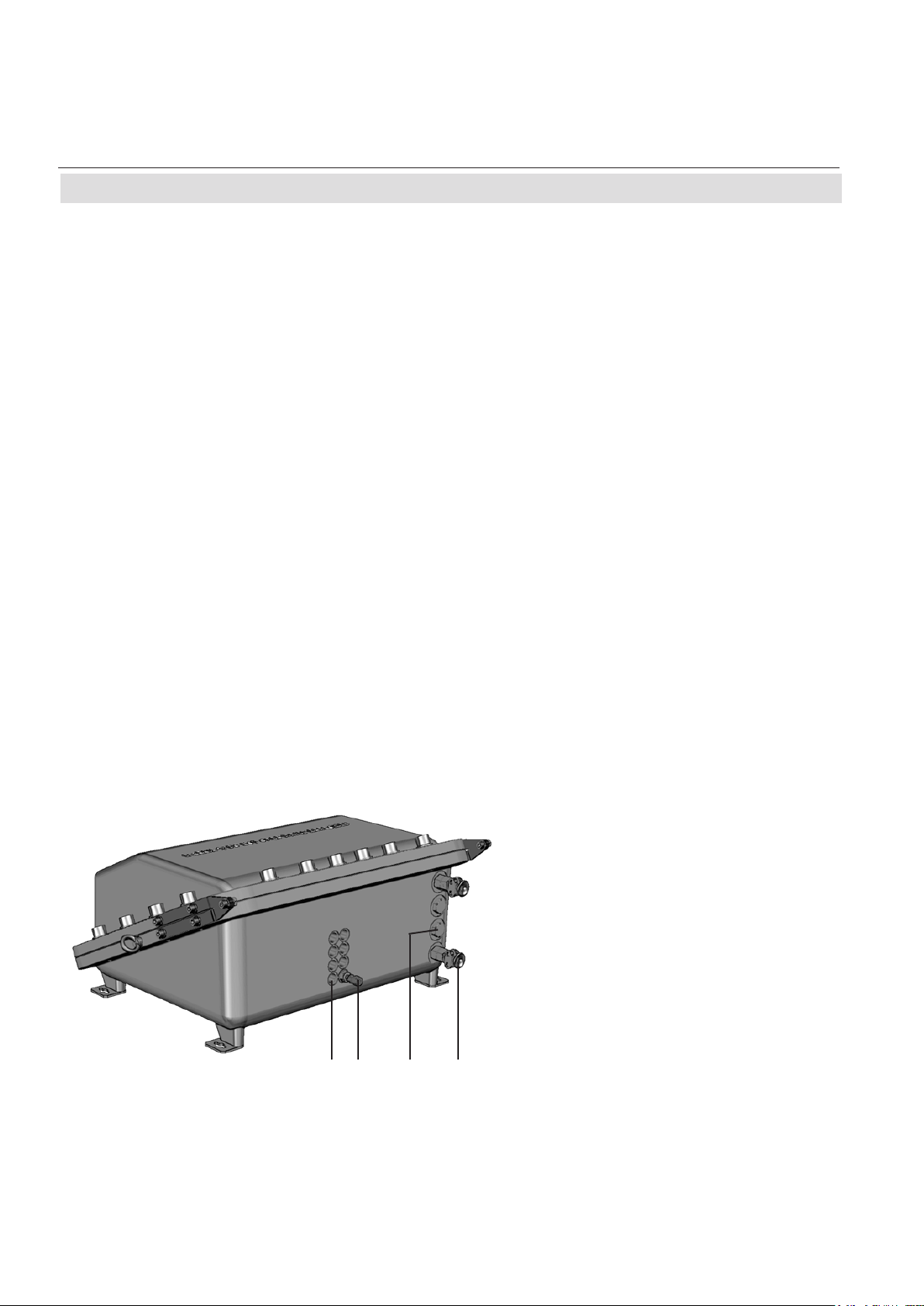
1-3 Protective Measures in Detail
The cast aluminum enclosure consists of
two parts: base and cover, connected by
hinges.
The area where the two parts are in contact
is designed to work as a ange, quenching
ames entering the small path between them.
When operated, the analyzer enclosure has to
be closed and secured by 20 screws evenly
arranged all over the ange.
6
3
1: Enclosure base
2: Screws
3: Enclosure cover
4: Flange
5: Eyebolts for lifting
6: Eyebolts for installation
7: Hinges
Fig. 1-1: X-STREAM FD
Emerson Process Management GmbH & Co. OHG 1-1
2
7
4
5
1
1 Technical Description
Page 14
X-STREAM FD
Emerson Process Management GmbH & Co. OHG1-2
Instruction Manual
HASADE-IM-EX
07/2007
1-3 Protective Measures in Detail
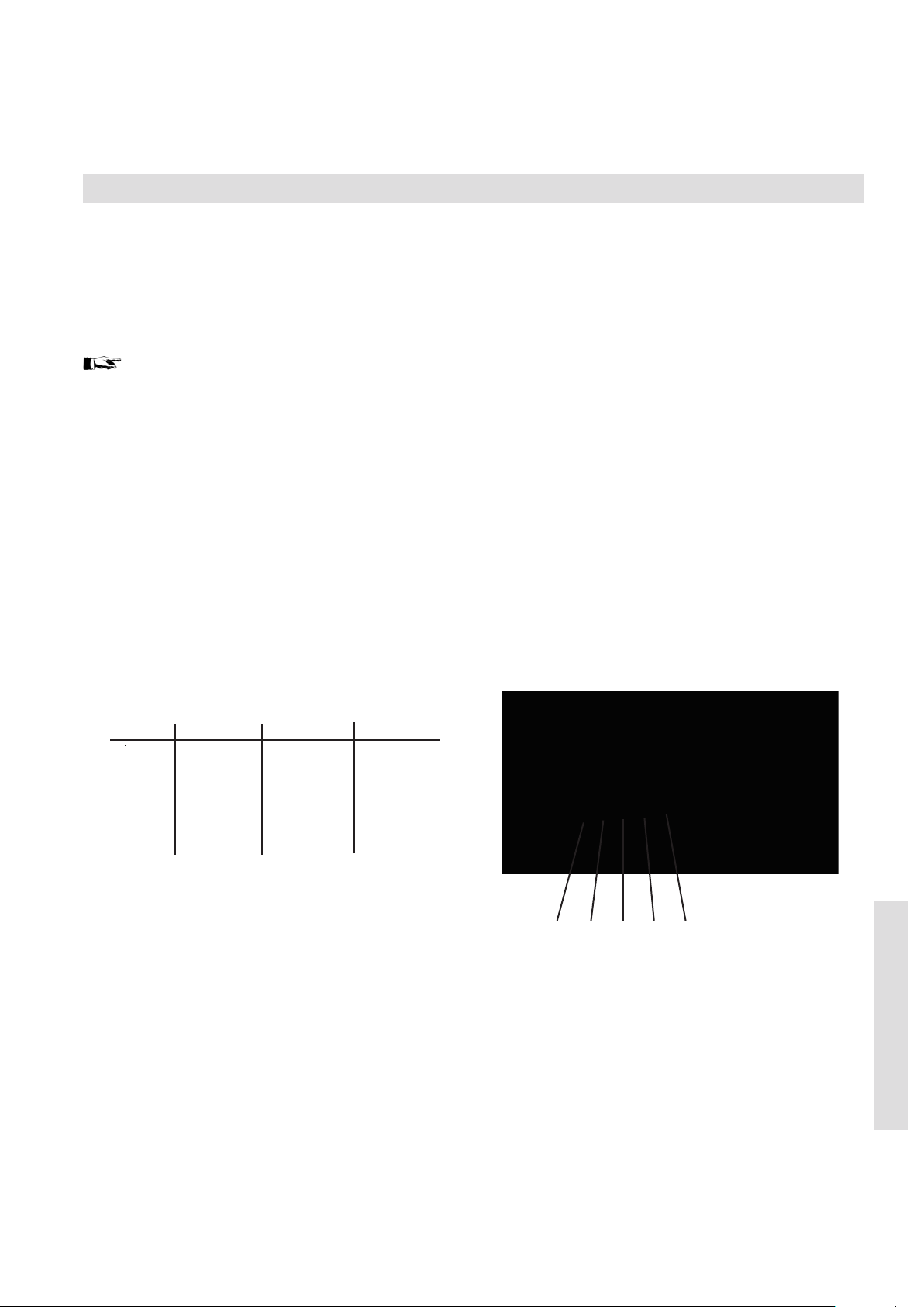
The only openings penetrating the enclosure
are threads, to be used for gas and cable inand outlets:
Depending on the measurement application
the instrument provides up to 8 gas in- and
outlets, each protected by an approved ame
arrestor. These arrestors are installed into
threads at the bottom side of the enclosure
base. Two tting sizes are available for external connection of gas pipes with 3.18 mm
(1/8“) or 6.35 mm (1/4“) outer diameter (OD).
Optionally a clamping ring for 6 mm OD may
be used, replacing the 6.35 mm version.
Cables are fed into the enclosure utilizing up
to 4 cable glands, located at the enclosure`s
bottom right side. The approved glands accept
3 different internal elastomeric sealing rings
with different internal diameters, supporting
a wide range of cables.
For installation in North-America cable glands
are replaced by a combination of conduits and
metric-to-NPT thread adapters.
All threads provide a ame path of a length
ensuring that possibly entering ames are
extin-guished before reaching the external
atmos-phere.
Unused threads must be closed with plugs
when the instrument is operated to ensure
explosion protection.
Note!
See the X-STREAM series instruction manual
for more information about common X-STREAM
series gas analyzers features and special
features of the X-STREAM FD.
1: Plugged when not used
2: Gas tting (part of ame arrestor)
3: Plug
4: Cable gland (or conduits)
1 2 3 4
Fig. 1-2: X-STREAM FD, bottom view
Page 15

Instruction Manual
HASADE-IM-EX
07/2007
X-STREAM FD
1-4 Compliances
1-4 Explosion Protection Compliances
This product is available in two different variations, separately certied by agencies for the use
in hazardous (classied) areas:
The one version, to be equipped with metric-to-NPT adapters and conduits (these components
are not part of the instrument certication), is certied by the Canadian Standards Association,
an „OSHA Nationally Recognized Testing Labor tory“ (NRTL), for Canada and USA and conforms
to the provisions of CAN/CSA-E60079-0:02 (R2006), CAN/CSA-E60079-1:02 (R2006), ANSI/ISA-
12.00.01-2002 (IEC 60079-0 Mod), ANSI/ISA-12.22.01-2002 (IEC 60079-1 Mod).
The second variation, to be equipped with cable glands, is certied by Fyzikálně technický
zkušební ústav, s.p (FTZÚ), an European Notied Body under the Directive 94/9/EC („ATEX“)
and conforms to the provisions of EN 60079-0 and EN 60079-1. See appendix for a copy of the
CE type examination certicate.
Depending on the variation, the following certication markings apply to the product:
Class I, Zone 1, AEx d IIB + H2 T3
USA
Canada Class I, Zone 1, Ex d IIB + H2 T3
European Union (EU) ATEX, category 2, Zone 1, Ex d IIB + H2 T4
EC ATEX Type Examination Certicate: FTZU 06 ATEX 0186.
Conforms with the provisions of the „Equipment intended for use in Potentially Explosive Atmospheres (ATEX)“ Directive 94/9/EC, EMC Directive 89/336/EEC and CE Directive 93/68/EEC.
1 Technical Description
Emerson Process Management GmbH & Co. OHG 1-3
Page 16

X-STREAM FD
Emerson Process Management GmbH & Co. OHG1-4
Instruction Manual
HASADE-IM-EX
07/2007
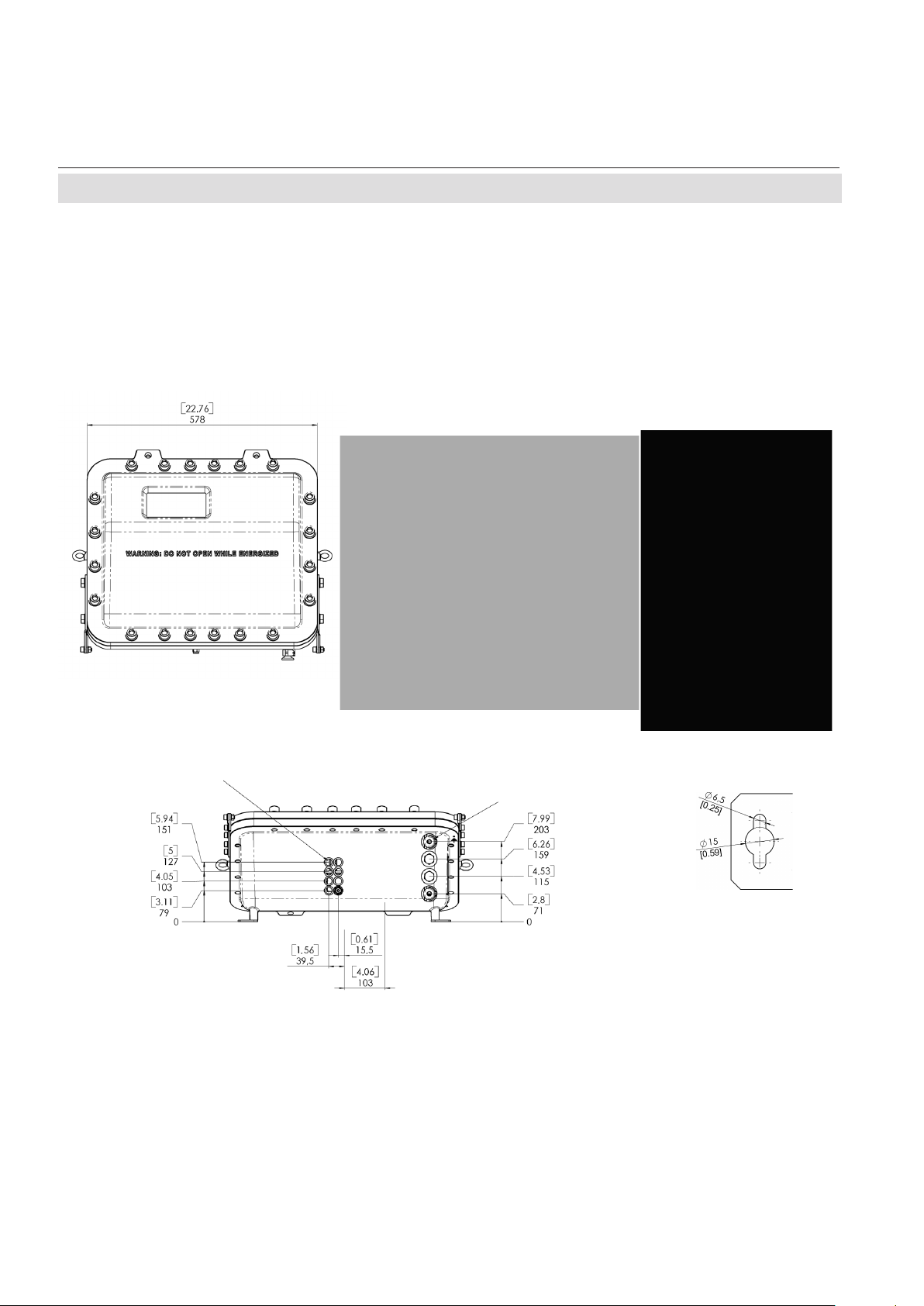
1-5 Technical Data
1-5 Technical Data
Flame arrestors with gas ttings
(enclosure threads: M18 x 1.5)
(enclosure threads; M20 x 1.5)
Cable inlets
Eyebolt detail
approx. in mm [inches]
Fig. 1-3: X-STREAM FD - dimensions
Housing
Permissible ambient temperature range -22 F to 122 F ( -30 °C to +50 °C)
Weight: approx. up to 139 lbs (63 kg)
(depending on analyzer conguration)
Protection class: IP 66 (EN 60529) / NEMA 4X
for outdoor installation
Analyzer must not be exposed to direct
sun light
Gas ttings: quantity: max. 8
specication: ame arrestors with ttings
6/4 mm or 1/4“, stainless steel
Page 17

Instruction Manual
HASADE-IM-EX
07/2007
X-STREAM FD
1-5 Technical Data
Site of installation
Humidity (non condensing) < 90 % r. h. at 68 F (+20 °C)
< 70 % r. h. at 104 F (+40 °C)
Pollution degree 2
Installation category I I
Altitude 0 to 6560 ft (2000 m) above sea level
Sourrounding atmosphere Analyzers must not be operated in
corrosive atmosphere.
General Purpose Compliances
Electrical safety CAN / USA CSA-C/US, based on
CAN/CSA-C22.2 No. 61010-1-04 /
UL 61010-1, 2nd Edition
Europe CE, based on EN 61010-1
Electromagnetic compatibility
Europe CE, based on EN 61326
other NAMUR
Power supply
Rated input voltageated input voltage
100 - 240 V 50/60 Hz, wide range input
Power supply voltage uctuations are
not to exceed +/- 10 % of the nominal
supply voltage!
Input voltage range 85 - 264 V , 47 - 63 Hz
Rated input current
standard 0,75 - 0,35 A max.
with thermostated physics 2 - 1 A max.
1 Technical Description
Emerson Process Management GmbH & Co. OHG 1-5
Page 18

X-STREAM FD
Emerson Process Management GmbH & Co. OHG1-6
Instruction Manual
HASADE-IM-EX
07/2007
1-5 Technical Data
Interfaces, signal inputs / outputs
2 analog outputs channel 4 (0) - 20 mA (RB < 500 Ω)
(optically isolated; congurable by keypad
start and end concentration user congurable)
Modbus interface RS 485 (2- or 4-wire)
optional:
RS 232 with or without optical isolation
Ethernet (RJ45 socket)
3 relay outputs (option „status signals“) “Failure”
according NAMUR NE 107 “Maintenance required / Off specication“
“Function check”
dry contacts, max. 30 V; 1 A; 30 W resistive
Digital Inputs and Outputs (option)
7 digital inputs zero calibration ch1 & ch2,
(common ground) span calibration ch1,
span calibration ch2,
open valve V4
open valve V1
open valve V2
open sample gas valve V3 /
switch off sample pump
max. 30 V, internally limited to 2.3 mA
H level: min. 4 V; L level: max. 3 V
8 digital outputs 2 thresholds per channel,
(optically isolated, common ground) sample gas valve,
zero gas valve V4,
span gas valve V1,
span gas valve V2
“Open Collector”, max. 30 V / 30 mA
Gas parameters
X-STREAM Instruction Manual, chapter 3 Measuring Principles
Page 19

Instruction Manual
HASADE-IM-EX
07/2007
X-STREAM FD
1-5 Technical Data
Power Connection
Connection via internal screw terminals near
cable entries, (g. 2-8).
Cross section: max. 10 AWG (4 mm2), using conductor
sleeves is not required
Cable entry via 1 cable gland, classied IP 68 or suitable
conduit with metric-to-NPT adaptor
Permissible outer cable diameter for power
cord when provided with cable glands: 0.11 to 0.5 inch (3-13 mm),
depending on used cable gland sealing ring
Power fuses
The power terminals integrate fuse holders.
Fuse ratings: AC 230 V, 3.15 A, 5x20 mm
324 1
1 Technical Description
1 Power terminals with integrated
fuse holders
2 Protective earth terminal (PE)
Fig. 1-4: X-STREAM FD - power terminals / fuse holders
Emerson Process Management GmbH & Co. OHG 1-7
3 Power cable entry
4 EMI power lter
Page 20

Instruction Manual
X-STREAM FD
HASADE-IM-EX
07/2007
1-5 Technical Data
Signal inputs / outputs
All signal lines need to be connected to internal
screw terminals (g. 1-5), except the optional RJ45 ethernet connector.
Cross section: max. 12 AWG (2.5 mm2), using conductor
sleeves is not required
Cable entry via
3 cable glands, classied IP 68 or suitable
conduits with metric-to-NPT adaptors
Permissible outer cable diameter for signal
cables when provided with cable glands: 0.11 to 0.5 inch (3-13 mm)
depending on used cable gland sealing rings
Available signals: standard: Analog signal outputs
Relay status signals
Modbus interface (RS232; RS 485)
optional: Digital inputs/outputs
Modbus RJ45 ethernet connector
Detailed pin assignment 2 Installation
The optional ethernet connector (RJ45),
Fig. 1-5: X-STREAM FD - signals terminals
Emerson Process Management GmbH & Co. OHG1-8
located on the electronics
main board BKS
Page 21

Instruction Manual
HASADE-IM-EX
07/2007
Installing and wiring this instrument must comply with all relevant national
legislative requirements and regulations.
Consider all safety instructions within this on hand manual and all associated analyzer instruction manuals!
X-STREAM FD
Chapter 2
Installation
POSSIBLE EXPLOSION HAZARD
POSSIBLE EXPLOSION HAZARD
Installing this instrument requires opening the enclosure and working at
the open instrument. This is permitted only when both no hazardous atmosphere is present and the instrument and connected external circuitry are
de-energized!
Depending on the local regulation, this may require a competent hot work
supervisor to issue a hot work permit.
HEAVY INSTRUMENT
The analyzer model X-STREAM FD, to which this manual relates, intended
to be wall mounted and/or outdoor installed, weighs up to approx. 63 kg
(139 lbs), depending on included options!
Use two people and/or suitable tools for transportation and lifting these
instruments!
Take care to use anchors and bolts specied to be used for the weight of
the units!
Take care the wall or stand the unit is intended to be installed at is solid and
stable to hold the units!
2 Installation
Emerson Process Management GmbH & Co. OHG 2-1
Page 22
Emerson Process Management GmbH & Co. OHG2-2
Instruction Manual
HASADE-IM-EX
07/2007
X-STREAM FD
2-1 Installing the Analyzer
2-1 Installation - Analyzer
Install the analyzer to a stand or a wall by
means of 4 eyebolts, provided at the instruments rear side.
It is recommended to install the analyzer in an
Note!
Add 15 [0.59] to left and right side to include
hinges.
upright (vertical) position; other orientations
may affect the measuring results.
Flame arrestors with gas ttings
Fig. 2-1: X-STREAM FD dimensions
Electrical connections
Eyebolt detail
All dimensions in mm
[inches in brackets]
Page 23

Instruction Manual
HASADE-IM-EX
07/2007
2-2 Connecting Gas Lines
X-STREAM FD
2-2 Installation - Gas Lines
Gas inlets and outlets are protected by certied ame arrestors (FTZU 06 ATEX 0164),
suppor-ting stainless steel pipes of either 3,18
mm (1/8“) or 6,35 mm (1/4“) outer diameter
(OD). The 1/4“ tting may optionally be supplied
with a clamping ring for 6 mm OD pipes.
POSSIBLE EXPLOSION HAZARD
Take care not to damage the threats, this may void the instrument´s safety
and cause hazards!
Take care to follow the instructions of the separate ame arrestor instruction
manual (HASFAE-IM-H)!
Ensure unused entries remain sealed with approved plugs!
When thightening the tting, counterhold the
ame arrestor with a wrench placed at the
hexagon (items 5 of g. 2) next to the cap
nut (items 1, 4) to be tightened.
Always counterhold the ame
arrestor while thightening ttings; otherwise the ame arrestor may be damaged!
The instrument provides up to 8 gas inlets and
outlets, depending on the ordered conguration. Unused entries are closed by approved
plugs.
1
5
2
3
6
5
7
4
1: Gas tting 1/8“ (inside instrument) *
2: M18 male threat (inside enclosure wall)
3: O-ring
4: Gas tting 1/4“ or 1/8“ (outside instrument) *
5: Hexagon for counter holding while thightening
6: Hexagon for wrench when mounting into a M18 threat
7: O-ring shoulder
*) FA 01 with 1/4“ (outside instrument) and 1/8“ (inside)
FA 02 with 1/4“ at both ends
FA 03 with 1/8“ at both ends
Fig. 2-2: Flame arrestor installed
into instrument enclosure
Emerson Process Management GmbH & Co. OHG 2-3
Fig. 2-3: Flame arrestor elements,
considering as example FA 01
)
)
2 Installation
Page 24

Emerson Process Management GmbH & Co. OHG2-4
Instruction Manual
HASADE-IM-EX
07/2007
X-STREAM FD
2-2 Installation - Gas Lines
Gas ttings are accessible at the instrument‘s
outer bottom side.The number and assignment of gas inlet and outlet ttings depends
on the application and is given on a label attached to the analyzer‘s bottom side adjacent
to the ttings.
For simple installation we recommend to mark
the gas lines according to the marking on the
analyzer label. This avoids confusion during
re-installation when the analyzer had to be
disconnected for whatever reason.
Page 25

Instruction Manual
HASADE-IM-EX
07/2007
2-3 Installation - Electrical
2-3 Electrical Installation
ELECTRICAL SHOCk H AZARD
Installation and connecting power and signal cables are subject to qualied
personnel only taking into account all applicable standards and legislative
requirements!
Failure to follow may cause warranty invalidation, property damage and/or
personal injury or death!
Installation of these instruments is subject to qualied personnel only,
familiar with the resulting potential risks! Instruments providing screw
terminals for electrical connections may require working near live part!
X-STREAM FD
X-STREAM FD gas analyzers do not provide a power switch!
A power switch or circuit breaker (complying with IEC 60947-1/-3) has to be
provided in the building installation. This switch has to be installed near
by analyzer, must be easily operator accessible and has to be assigned as
disconnector for the analyzer.
Disconnect instruments with screw terminals from power when working at
power terminals (pull power plug or operate power switch/ circuit breaker
in building installation)!
The analyzers provide a protective earth terminal. To prevent electrical shock
hazards the instruments must be connected to a protective earth. Therefore
the instruments must be connected to power by using a three wire power
cable with earth conductor!
Any interruption of the earth connector inside or outside the instrument
or disconnecting the earth terminal may cause potential electrical shock
hazzard!
The analyzers do not provide a power switch and are operable when connected to power.
Emerson Process Management GmbH & Co. OHG 2-5
2 Installation
Page 26
Emerson Process Management GmbH & Co. OHG2-6
Instruction Manual
HASADE-IM-EX
07/2007
X-STREAM FD
Do not open instrument when energized.
Ensure that external circuitry is disconnected or de-energized before
opening the instrument.
All cables (power and signal) must end (be connected) in either a safe (non-
hazardous) area or in a protecting enclosure (e.g. Ex e junction box)!
2-3 Installation - Electrical
POSSIBLE EXPLOSION HAZARD
SELECT THE CORRECT TYPE OF CABLE ENTRY
Before starting to install the analyzer, verify what type of cable entry is required at your
site of installation:
X-STREAM FD gas analyzers may be equipped with cable glands (regulated e.g. for installations covered by ATEX) or may be installed with conduits (e.g. in North-America).
INSTALLATION USING CONDUITS
X-STREAM FD analyzers provide metric threads for installing cable entries.
Installing conduits requires using metric-to-NPT adaptors!
To stay compliant with the North-American certication use only ameproof
certied adaptors, e.g. the following type:
Redapt AD-U series, stainless steel with captive o-ring seals,
size male M20 x 1.5 to female 3/4-NPT or 1/2-NPT.
Select a type of conduit according the local code, suitable for above
mentioned adaptors and the site of installation.
During installation follow the instructions provided by the manufacturer of
the conduits!
Unused entries must be provided with ameproof plugs, secured in place
with thread locking compound!
Page 27

Instruction Manual
HASADE-IM-EX
07/2007
When installing the analyzer in a Hydrogen environment and/or applying
Hydrogen to the analyzer, do not use the standard ADL type cable glands!
Use suitable compound barrier cable glands to stay compliant to EN 60079-14.
During installation follow the instructions provided by the manufacturer of
the glands!
When using the ADL type cable glands: Take care to use the correct cable
gland internal elastomeric ring with an internal diameter supporting the cable
to be used! The supported cable diameters are noted on the sealing ring.
X-STREAM FD
2-3 Installation - Electrical
INSTALLATION USING CABLE GLANDS
Use only cables as specied in the cable glands installation instruction, and
carefully follow the installation instructions!
The next two pages show
• the English section of the ADL type cable
gland installation instructions, reprinted with
the permission of
Cooper Industries
Cooper Menvier Division
CAPRI-CODEC sas .
and
• the English installation instructions for type
AD-U adapters, reprinted with the permission of
Redapt Ltd
Note!
See appendix of this manual for a complete
reprint, and the documentation delivered
together with your analyzer for an original
version of the cable gland or adapter installation instructions, where applicable !
2 Installation
Emerson Process Management GmbH & Co. OHG 2-7
Page 28

Emerson Process Management GmbH & Co. OHG2-8
Instruction Manual
HASADE-IM-EX
07/2007
X-STREAM FD
2-3 Installation - Electrical
Type AD-U adapter installation instructions
Page 29

Instruction Manual
HASADE-IM-EX
07/2007
ADL type cable gland installation instructions
X-STREAM FD
2-3 Installation - Electrical
The elastomeric sealing
rings, provided together
with the cable gland,
are designed to cover
the diameter ranges
3 to 8 mm
6,5 to 10.5 mm
or
10 to 13 mm.
Emerson Process Management GmbH & Co. OHG 2-9
2 Installation
Page 30

Emerson Process Management GmbH & Co. OHG2-10
Instruction Manual
HASADE-IM-EX
07/2007
X-STREAM FD
2-3 Installation - Electrical
The analyzer provides 4 cable entries and
is shipped with selected sets of plugs and
glands or adaptors, depending on the ordered
analyzer conguration:
The default set consists of
• 1 gland/adaptor for the power cord
• 1 gland/adaptor for one signal cable
• 3 plugs for unused entries, taking into
account an installation without even one
signal cable.
Unused entries during installation have to be
provided with plugs, secured in place with
thread locking compound.
Installation under CSA certication requires
the use of approved conduits and suitable
metric-to-NPT adaptors. .
The instrument provides internal screw terminals for connecting power and signal cables.
This requires opening the instrument during
installation:
• Unsrew the 20 screws located on the
enclosure ange.
• Flap down the cover part to gain access
to the analyzer inside.
1 42 35
1 Terminals for signal cables
2 Power EMI lter
3 4 cable entries for power and signal cables
4 Power terminals with integrated fuses
5 Ethernet connector (option)
Fig. 2-4: X-STREAM FD - allocation of terminals
Page 31

Instruction Manual
HASADE-IM-EX
07/2007
X-STREAM FD
2-3 Installation - Electrical
Installation with conduits
Ensure all required parts are available:
Adaptors, suitable conduits, plugs for not used
entries and compound (see accessory kit).
Place some locking compound onto the male
thread of the required number of adaptors and
install them into the related cable entries:The
3 rear entries are reserved for signal cables,
the rst one is for the power cord.
Ensure the explosionproof seal is placed
at the analyzer enclosure or within 2“ from
enclosure.
All cables need to be fed properly through
conduits when entering the instrument and
connected to the terminals (
warning
notes, page 2-5).
To seal the cable entries proceed according to
the installation instruction given in the related
conduits manufacturer documentation.
Seal unused entries utilizing ameproof certi-
ed plugs, also provided with some compound
on their threads.
Installation with cable glands
Ensure all required parts are available:
Cable glands, plugs for not used entries and
compound (see accessory kit).
Place some locking compound onto the male
thread of the required number of cable glands
body parts and install them according the
manufacturers instruction into the related
cable entry:The 3 rear entries are reserved
for signal cables, the rst one is for the power
cord.
All cables need to be fed properly through the
cable glands when entering the instrument
and connected to the terminals (
warning
notes, page 2-5).
To seal the cable entries proceed according to
the installation instruction given in the related
cable glands manufacturer documentation.
Seal unused entries utilizing the plugs, also
provided with some compound on their threads.
Preparation of signal cables
All signal cables are to be connected via
screw terminals, except the optional ethernet
connector, located inside the analyzer.
Supported wire cross sections: 24 to 14 AWG (0,2 to 2,5 mm2),
no need to use wire end sleeves
Cable skinning length: 0.354 inch (9 mm)
Hole diameter: 0.05 inch (1,2 mm)
Screw thread: M 2,5
Tightening torque, min: 3.5 in.lb (0,4 Nm)
Emerson Process Management GmbH & Co. OHG 2-11
2 Installation
Page 32

Emerson Process Management GmbH & Co. OHG2-12
Instruction Manual
HASADE-IM-EX
07/2007
X-STREAM FD
2-3 Installation - Electrical
Signal inputs / outputs
Analog signal outputs
The rightmost 4 terminals (# 1 - 4) of the terminals row next to the power terminals are
reserved for analog signal outputs.
Burden: RB ≤ 500 Ω
Note!
Take care of the special installation instructions in section 4-5 of the X-STREAM gas
analyzer series manual!
(-) 4 (0) - 20 mA, channel 2
(+) 4 (0) - 20 mA, channel 2
(-) 4 (0) - 20 mA, channel 1
(+) 4 (0) - 20 mA, channel 1
Fig. 2-5: X-STREAM FD - Analog output terminals
Page 33
Instruction Manual
HASADE-IM-EX
07/2007
2-3 Installation - Electrical
Modbus interface
Specication and driving the interface:
X-STREAM gas analyzer series manual,
chapter 7.
Note 1!
Take care of the special installation instructions in section 4-5 of the X-STREAM gas
analyzer series manual!
The leftmost 5 terminals (# 11 - 15) of the
terminals row next to the power terminals are
reserved for the Modbus interface, which can
be either of type RS 232 or RS 485.
X-STREAM FD
Terminal RS 232 RS 485/2w RS 485/4w
11 Common Common Common
12 RXD not used RXD0
13 TXD not used RXD1
14 not used D1 TXD1
15 Common D0 TXD0
Note 2!
X-STREAM analyzers are to be considered
a DTE (Data Terminal Equipment).
Fig. 2-6: X-STREAM FD - Modbus interface terminals
1112131415
2 Installation
Emerson Process Management GmbH & Co. OHG 2-13
Page 34

Emerson Process Management GmbH & Co. OHG2-14
Instruction Manual
HASADE-IM-EX
07/2007
X-STREAM FD
2-3 Installation - Electrical
Optional Modbus RJ45 connection
If installed, the optional RJ45 connector is
located on the BKS main board, in the upper
part of the instrument.
To install this connection one has to insert
a cable without connetor through the cable
inlet.
Once the open end is inside the instrument,
the plug connector can be installed:
We recommend using a VARIOSUB RJ45
QUICKON plug connector (PHOENIX CONTACT), as supplied together with the instrument, not requiring special tools. See the
separate installation instruction, provided
together with the plug connector for information on how to install it.
Note!
Notice, that the modbus screw terminals
( page 2-12) are installed, too, but without function!
Pin 1 Pin 8
Fig. 2-7: X-STREAM F - Modbus over ethernet connector
Pin Signal
1 TX+
2 TX 3 RX+
6 RX other not used
RJ45 connector on
main board BKS
Page 35

Instruction Manual
HASADE-IM-EX
07/2007
Relay status Signals
X-STREAM FD
2-3 Installation - Electrical
Design: dry relay contacts
Electrical specication: max. 30 V , 1 A,
30 W
Note!
Take care of the special installation instructions in section 4-5 of the X-STREAM gas
analyzer series manual!
The middle 6 terminals (# 5 - 10) of the terminals row next to the power terminals are
reserved for the relay status signals.
Signal output
(NC); conguration on request
Signal output
(NO); factory
standard conguration
Fig. 2-8: Relay status signals, block diagram
Terminal Signal
5 Failure COM
6 Failure NO
7 Maintenance, off-spec COM
8 Maintenance, off-spec NO
9 Function check COM
10 Function check NO
10
9
Fig. 2-9: X-STREAM FD - Relay Status Terminals
Emerson Process Management GmbH & Co. OHG 2-15
5678
2 Installation
Page 36
Emerson Process Management GmbH & Co. OHG2-16
Instruction Manual
HASADE-IM-EX
07/2007
X-STREAM FD
2-3 Installation - Electrical
Digital Inputs & Outputs
Design: Open collector (outputs)
Electrical specication:
outputs: max. 30 V , 30 mA
inputs: max. 30 V , internally limited to 2,3 mA
H level: min. 4 V; L level: max. 3 V
Note!
The leftmost terminal strip is reserved for the
digital inputs and outputs.
Take care of the special installation instructions in section 4-5 of the X-STREAM gas
analyzer series manual!
Digital Inputs DigitalOutputs
Terminal 13
Terminal 14
Terminal 15
Terminal 16
Terminal 17
Open V4
Open V1
Open V2
Open sample valve or close all
DIG In GND
Fig. 2-10: Digital Inputs & Outputs Terminals
Terminal 10
Terminal 11
Terminal 12
Zero cal. Ch1 & Ch2
Span cal. Ch1
Span cal. Ch2
Terminal 7
Terminal 8
Terminal 9
Valve V1
Valve V2
DIG Out GND
Terminal 4
Terminal 5
Terminal 6
Ch2: threshold 2
Sample valve
Valve V4
Terminal 1
Terminal 2
Terminal 3
Ch1: threshold 1
Ch1: threshold 2
Ch2: threshold 1
Page 37

Instruction Manual
HASADE-IM-EX
07/2007
X-STREAM FD
2-3 Installation - Electrical
Connecting the power cord
The power cord is connected by screw terminals, located inside analyzer.
Supported wire cross sections: 24 to 12 AWG (0,2 to 4 mm2),
no need to use wire end sleeves
Cable skinning length: 0.315 inch (8 mm)
Hole diameter: 0.05 inch (1,2 mm)
Screw thread: M 3
Tightening torque, min: 4.4 in.lb (0,5 Nm)
To install the cable proceed according to the
installation instructions for either conduits or
cable glands, given on page 2-11.
Insert the power cord through the foremost
entry, strip the outer insulation, skin and
connect the conductors to the terminals (a
descriptive label is xed to the lter‘s housing
nearby the terminals), by inserting them from
the bottom sides.
ELECTRICAL SHOCk HAZARD
Verify the power supply at installation site meets the specication given on
the analyzer´s nameplate label, before installing the instrument!
Location
for label
L
N
PE
L= Line
N=Neutral
PE=Protective Earth
Power cord
entry
Fig. 2-11: Power terminals
Verify power cables are disconnected and/or instrument is de-energized
prior to working at the terminals!
Verify the power cord is layed with a distance of at least 1 cm (0.5“) to any
signal cable to ensure proper insulation from signal circuits!
Emerson Process Management GmbH & Co. OHG 2-17
2 Installation
Page 38

Emerson Process Management GmbH & Co. OHG2-18
Instruction Manual
HASADE-IM-EX
07/2007
X-STREAM FD
2-3 Installation - Electrical
Connecting an optional equipotential
bonding conductor
The X-STREAM FD enclosure provides an
additional terminal for connecting an equipotential conductor, located at the base part
ange´s rear side (see g. 2-6), near the
nameplate label.
Screw thread: M5
Fig. 2-12: Equipotential bonding conductor terminal
Page 39

Instruction Manual
HASADE-IM-EX
07/2007
2-3 Installation - Electrical
ELECTRICAL SHOCk HAZARD
Before completing the electrical connection of the instrument, verify cables
are inserted and connected in correct manner!
Ensure the earthing conductor (protective earth; PE) is connected!
After all connections are established in correct
manner and veried,
• x the cables according to the installati-
on instruction given in the cable glands/
conduits manufacturer documentation.
• Install the analyzer´s cover by means of
ALL 20 screws!
Tightening torque: min. 354 in.lb (40 Nm)
X-STREAM FD
POSSIBLE EXPLOSION HAZARD
Do NOT operate the instrument with doors or covers open! This is permitted
only when no hazardous atmosphere is present!
Depending on the local regulation, this may require a competent hot work
supervisor to issue a hot work permit.
Use ALL 20 screws to x the cover! Violation may cause an explosion
hazard!
Emerson Process Management GmbH & Co. OHG 2-19
2 Installation
Page 40

X-STREAM FD
Instruction Manual
HASADE-IM-EX
07/2007
2-3 Installation - Electrical
Emerson Process Management GmbH & Co. OHG2-20
Page 41

Instruction Manual
HASADE-IM-EX
04/2007
X-STREAM FD
Chapter 3
Startup
Once the X-STREAM FD analyzer is installed
correctly and in accordance to the instructions given in chapter2 „Installation“ it is
prepared for startup.
POSSIBLE EXPLOSION HAZARD
Ensure all covers, plugs and housing parts are in place and secured properly
before supplying power and signal voltages!
Ensure all requirements given
by the clarication sheet for
performing gas analysis within
a ameproof enclosure are
considered BEFORE supplying
gases (see page S-5)!
The sheet also gives instructions for the sequence of supplying gases during process and
analyzer startup .
3 Startup
After all safety aspects are followed and
checked, the instrument may be powered and
operated according the instructions given in
the X-STREAM series instruction manual.
Read this manual for detailled information
about software, parameter settings and
more.
Emerson Process Management GmbH & Co. OHG 3-1
Page 42

X-STREAM FD
Instruction Manual
HASADE-IM-EX
04/2007
3 Startup
Emerson Process Management GmbH & Co. OHG3-2
Page 43

Instruction Manual
HASADE-IM-EX
07/2007
X-STREAM FD
Chapter 4
Service and Maintenance
Note!
This chapter deals with service and maintenance procedures related to explosion protection only!
More detailled instructions about servicing and maintaining general purpose components of
X-STREAM gas analyzers are subject of the X-STREAM analyzer instruction manual.
POSSIBLE EXPLOSION HAZARD
Inspection, maintenance and service must be carried out considering all
related standards (e.g. EN 60079-17 „Inspection and maintenance of
electrical installations in hazardous areas (other than mines)“ ).
POSSIBLE EXPLOSION HAZARD
Service or replacement of safety related components or requiring to open
the instrument are permitted only if no hazardous atmosphere is present
and both the instrument and connected circuitry are de-energized!
Depending on the local regulation this may require a competent hot work
supervisor to issue a hot work permit.
POSSIBLE EXPLOSION HAZARD
After maintenance or replacement of parts concerning explosion protection
an authority on explosion protection has to verify that the analyzer still meets
the requirements for explosion protection before it is switched on again.
Parts essential for explosion protection must not be repaired, they must be
replaced if defective!
4 Maintenance
The authority has to issue a certicate for this and/or attach a test label to
the equipment before startup after maintenance or replacement of parts.
Emerson Process Management GmbH & Co. OHG 4-1
Page 44

Emerson Process Management GmbH & Co. OHG4-2
X-STREAM FD
Instruction Manual
HASADE-IM-EX
07/2007
FLAMMABLE GASES - POSSIBLE EXPLOSION HAZARD
Leaks may cause explosion when measuring ammable gases!
When measuring ammable gases it is recommended to perform a leak test
on all gas paths, connections and components before startup or applying
power. Leak tests should be carried out on a 2 month‘s regular basis and
after repair/maintenance.
See the analyzer instruction manual for instructions on how to carry out
leak tests.
4 Service and Maintenance
HAZARDOUS GASES
When measuring ammableand/or toxic gases it is recommended to purge
the system with air or an inert gas, e.g. nitrogen, prior to opening the gas
paths.
Violation may cause an explosion and/or personal injury or death!
POSSIBLE EXPLOSION HAZARD
Modications affecting the integrity of type of protection (e.g. afxing
addtional threads, replacing the ame arrestors by other model) are NOT
PERMITTED!
Violation may cause an explosion and/or personal injury or death!
Page 45

Instruction Manual
HASADE-IM-EX
07/2007
4-1 Verications and Tests after Service or Maintenance
4-1 Verications and Tests after Service or Maintenance
Modications made on the electrical apparatus affecting the integrity of the type of protection or the temperature of the apparatus shall
be permitted only if the modied apparatus is
resubmitted to a testing station.
In the case of repairs affecting the type of
protection, the parts which have been repaired should be subjected to new routine
verications and tests. These tests need not
necessarily be made by the manufacturer.
4-1-1 Routine Tests
X-STREAM FD
The following tests shall be performed on a
regular basis:
4-1-1-1 Visual Inspection
The instrument shall be visually checked for
damages to the enclosure and external analyzer components.
4-1-1-2 Tests on Flame Arrestors
Depending on the application ame arrestors
should be checked periodically according
the information given in the ame arrestors
instruction manual.
4 Maintenance
Emerson Process Management GmbH & Co. OHG 4-3
Page 46
Emerson Process Management GmbH & Co. OHG4-4
X-STREAM FD
Instruction Manual
HASADE-IM-EX
07/2007
4-2 Replacement of Parts
4-2 Replacement of Parts
POSSIBLE EXPLOSION HAZARD !
Replacement of parts found defective is permitted only by using original
parts!
Violation voids the approvals and may cause explosions!
Parts beside the cast enclosure, the safety of the X-STREAM FD relies on:
Cable glands, standard
for ATEX approved analyzers
Type: ADL 1F ISO 20 No. 05 by CAPRI
LCIE 97 ATEX 6006 X
Compound Cable glands (optional)
for ATEX approved analyzers
Type: to be selected for the installed cable
and with ATEX (EU) or suitable local approval
(outside EU)
Male thread: M20 x 1.5
Available from several manufacturers, e.g.
type CR-X by PeppersCable Glands Limited
Cable entries stopping plugs
for ATEX approved analyzers
Type: 120209 by CAPRI
Male thread: M20 x 1.5
98 ATEX 0001U
Metric-to-NPT adapters
for CSA approved analyzers
Any ameproof certied type
Male thread: M20 x 1.5
Female thread: 1/2“ or 3/4“ per request
e.g.
Type: AD-U series by Redapt Ltd.
CSA certicate 1248014
Page 47

Instruction Manual
HASADE-IM-EX
07/2007
X-STREAM FD
4-2 Replacement of Parts
Cable entries stopping plugs
for CSA approved analyzers
Any ameproof certifed type
Male thread: M20 x 1.5
e.g.
Type: PD-U by Redapt Ltd.
CSA certicate 1248014
Flame arrestors
Type: FA 01, FA 02, FA 03
by EMERSON PROCESS MANAGEMENT
FTZU 06 ATEX 0164
Enclosure screws
Material: stainless steel A2-70
Thread: M16 x 45 ISO 4762 A2
Thread locking adhesive
Type: ML® 5249 by DELO
Internal battery (soldered to electronics board,
not user replaceable)
Type: SL 750 by Tadiran Batteries GmbH
System: SOCl2 / Li
Nom. voltage: 3.6 VNom. voltage: 3.6 V
IEC 60086-1 type E cell
4 Maintenance
Emerson Process Management GmbH & Co. OHG 4-5
Page 48

X-STREAM FD
Instruction Manual
HASADE-IM-EX
07/2007
4-2 Replacement of Parts
Emerson Process Management GmbH & Co. OHG4-6
Page 49

Instruction Manual
HASADE-IM-EX
07/2007
X-STREAM FD
Appendix
This chapter contains
EC Declaration of Conformity A-1, page A-2
ATEXECTypeExaminationCerti.cate A-2, page A-3
Cable gland ADL 1F installation instruction A-3, page A-7
Block diagram A-4, page A-8
Assignment of Terminals and Socket A-5, page A-9
Appendix
Emerson Process Management GmbH & Co. OHG A-1
Page 50

Emerson Process Management GmbH & Co. OHGA-2
Instruction Manual
HASADE-IM-EX
07/2007
X-STREAM FD
A-1 EC Declaration of Conformity
A-1 EC Declaration of Conformity
Page 51

Instruction Manual
HASADE-IM-EX
07/2007
A-2ATEXECTypeExaminationCerticate
A-2 ATEXECTypeExaminationCerti.cate
X-STREAM FD
Appendix
Emerson Process Management GmbH & Co. OHG A-3
Page 52

Emerson Process Management GmbH & Co. OHGA-4
Instruction Manual
HASADE-IM-EX
07/2007
X-STREAM FD
A-2ATEXECTypeExaminationCerticate
Page 53

Instruction Manual
HASADE-IM-EX
07/2007
X-STREAM FD
A-2ATEXECTypeExaminationCerticate
Appendix
Emerson Process Management GmbH & Co. OHG A-5
Page 54

X-STREAM FD
Instruction Manual
HASADE-IM-EX
07/2007
Emerson Process Management GmbH & Co. OHGA-6
Page 55

Instruction Manual
HASADE-IM-EX
07/2007
A-3 Cable gland ADL 1F installation instruction
X-STREAM FD
A-3 Cable Gland Installation Instruction
(reprinted with the
permission of
Cooper Industries
Cooper Menvier Division
CAPRI-CODEC sas. )
Appendix
Emerson Process Management GmbH & Co. OHG A-7
Page 56

X-STREAM FD
A-4 Block diagram X-STREAM FD
Instruction Manual
HASADE-IM-EX
07/2007
A-4 Block Diagram
Emerson Process Management GmbH & Co. OHGA-8
Page 57

Instruction Manual
HASADE-IM-EX
07/2007
A-5 Assignment of Terminals and Socket
56789101112131415 1234
A-5 Assignment of Terminals and Socket
Terminal 16
Terminal 17
Terminal 14
Terminal 15
Terminal 12
Terminal 13
Terminal 11
Terminal 9
Terminal 10
Terminal 7
Terminal 8
Terminal 5
Terminal 6
Terminal 3
Terminal 4
Terminal 1
Terminal 2
X-STREAM FD
Appendix
Terminal RS 232 RS 485/2d RS 485/4d
11 Common Common Common
12 RXD not used RXD0
13 TXD not used RXD1
14 not used D1 TXD1
15 Common D0 TXD0
Modbus interface
Fig. A-1: Terminals strip 1
Pin 1 Pin 8
Fig. A-4: Ethernet connector for Modbus
Terminal Signal
5
6
7
8
9
10
Failure COM
Failure NO
Maintenance, off-spec COMMON
Maintenance, off-spec NO
Function check COMMON
Function check NO
Relay outputs
Pin Signal
1 TX+
2 TX 3 RX+
6 RX andere nicht
verwendet
Terminal Signal
1 (+) 4 (0) - 20 mA, ch 1
2 (-) 4 (0) - 20 mA, ch 1
3 (+) 4 (0) - 20 mA, ch 2
4 (-) 4 (0) - 20 mA, ch 2
Burden: RB ≤ 500 Ω
Analog outputs
DIG inputs COMMON
Fig. A-2: Terminals strip 2
Fig. A-3: Power terminals
Valve V2
DIG outputs COMMON
Ch1 & Ch2: Zero cal.
Ch1: Span cal.
Ch2: Span cal.
Valve V4
Valve V1
Valve V2
Open sample valve, close all, or pump on/off
Digital Inputs Digital Outputs
Protective Earth PE
Valve V4
Valve V1
Ch2: threshold 1
Ch2: threshold 2
Sample valve
Ch1: threshold 1
Ch1: threshold 2
*)
*)
With optional range switching this
output is used as range indicator
( X-STREAM series instruction
manual, section 7-7-5, page 7-58)
Line L
Neutral N
Note!
Line and neutral terminals with builtin fuse holders
Emerson Process Management GmbH & Co. OHG A-9
Page 58

X-STREAM FD
Instruction Manual
HASADE-IM-EX
07/2007
Emerson Process Management GmbH & Co. OHGA-10
Page 59

Instruction Manual
HASADE-IM-Ex
04/2007
X-STREAM FD
Page 60

X-STREAM FD
WORLD HEADQUARTERS
ROSEMOUNT ANALYTICAL EUROPE
Emerson Process Management
GmbH & Co. OHG
Industriestrasse 1
63594 Hasselroth
Germany
T 49 6055 884 0
F 49 6055 884209
Emerson Process Management
Rosemount Analytical Inc.
6565 P Davis Industrial Parkway
Solon, OH 44139 USA
T 440.914.1261
Toll Free in US and Canada 800.433.6076
F 440.914.1271
e-mail: gas.csc@EmersonProcess.com
www.raihome.com
Instruction Manual
HASADE-IM-Ex
04/2007
GAS CHROMATOGRAPHY CENTER
AND LATIN AMERICA
Emerson Process Management
Rosemount Analytical Inc.
11100 Brittmoore Park Drive
Houston, TX 77041
T 713 467 6000
F 713 827 3329
EUROPE, MIDDLE EAST AND AFRICA
Emerson Process Management
Shared Services Limited
Heath Place
Bognor Regis
West Sussex PO22 9SH
England
T 44 1243 863121
F 44 1243 845354
ASIA-PACIFIC
Emerson Process Management
Asia Pacic Private Limited
1 Pandan Crescent
Singapore 128461
Republic of Singapore
T 65 6 777 8211
F 65 6 777 0947
e-mail: analytical@ap.emersonprocess.com
© 2007 Emerson Process Management GmbH & Co. OHG
Loading...