

X-STREAM Non-Incendive Analyzers Manual Addendum for Zone 2 and Div. 2 Hazardous Area Applications-2nd Ed.
Table of contents
 Loading...
Rosemount X-STREAM Non-Incendive Analyzers Manual Addendum for Zone 2 and Div. 2 Hazardous Area Applications-2nd Ed. Manuals & Guides
Page 1

Some notes for navigating in this PDF document
Page references of
this style work as hyperlinks: Simply click
on the page number to
open that page.
To open a specic
page you can now
enter the logical page
number just as it appears in the footer.
Page 2

Page 3

Instruction Manual
HASXENE-IM-EX
03/2010
Non-Incendive Gas Analyzer
X-STREAM X2 series and X-STREAM XE series
Instruction Manual Addendum for
Zone 2 Hazardous Area Applications
www.EmersonProcess.com
Page 4

ESSENTIAL INSTRUCTIONS
READ THIS PAGE BEFORE PROCEEDING!
Emerson Process Management (Rosemount Analytical) designs, manufactures and tests
its products to meet many national and international standards. Because these instruments
are sophisticated technical products, you MUST properly install, use, and maintain
them to ensure they continue to operate within their normal specications. The following
instructions MUST be adhered to and integrated into your safety program when installing,
using and maintaining Emerson Process Management (Rosemount Analytical) products.
Failure to follow the proper instructions may cause any one of the following situations
to occur: Loss of life; personal injury; property damage; damage to this instrument; and
warranty invalidation.
• Read all instructions prior to installing, operating, and servicing the product.
• If you do not understand any of the instructions, contact your Emerson Process
Management (Rosemount Analytical) representative for clarication.
• Follow all warnings, cautions, and instructions marked on and supplied with the
product.
• Inform and educate your personnel in the proper installation, operation, and
maintenance of the product.
• Install your equipment as specied in the Installation Instructions of the
appropriate Instruction Manual and per applicable local and national codes.
Connect all products to the proper electrical and pressure sources.
• To ensure proper performance, use qualied personnel to install, operate, update,
program, and maintain the product.
• When replacement parts are required, ensure that qualied people use replacement
parts specied by Emerson Process Management (Rosemount Analytical).
Unauthorized parts and procedures can affect the product’s performance, place the
safe operation of your process at risk, and VOID YOUR WARRANTY. Look-alike
substitutions may result in re, electrical hazards, or improper operation.
• Ensure that all equipment doors are closed and protective covers are in place,
except when maintenance is being performed by qualied persons, to prevent
electrical shock and personal injury.
The information contained in this document
is subject to change without notice.
nd
2
Edition 2010-03
Emerson Process Management GmbH & Co. OHG
Industriestrasse 1
D-63594 Hasselroth
Germany
T +49 (0) 6055 884-0
F +49 (0) 6055 884-209
Internet: www.EmersonProcess.com
Original Instruction Manual for the purpose
of the European Directive 94/9/EC.
Page 5

Instruction Manual
HASXENE-IM-EX
03/2010
X-STREAM Non-Incendive
Table of ConTenTs
Introduction S-1
Denitions S-1
Terms used in this instruction manual . . . . . . . . . . . . . . . . . . . . . . . . . . . . . . . . . . . . . . . . . . S-2
Symbols used on and inside the unit . . . . . . . . . . . . . . . . . . . . . . . . . . . . . . . . . . . . . . . . . . . S-3
Symbols used within this manual
. . . . . . . . . . . . . . . . . . . . . . . . . . . . . . . . . . . . . . . . . . . . . . S-4
Safety Instructions S-5
Intended Use Statement. . . . . . . . . . . . . . . . . . . . . . . . . . . . . . . . . . . . . . . . . . . . . . . . . . . . . S-5
General safety notice / Residual risk
Authorized personnel . . . . . . . . . . . . . . . . . . . . . . . . . . . . . . . . . . . . . . . . . . . . . . . . . . . . . . . S-6
Additional Literature . . . . . . . . . . . . . . . . . . . . . . . . . . . . . . . . . . . . . . . . . . . . . . . . . . . . . . . . S-6
Operating and Maintaining this Apparatus . . . . . . . . . . . . . . . . . . . . . . . . . . . . . . . . . . . . . . S-15
. . . . . . . . . . . . . . . . . . . . . . . . . . . . . . . . . . . . . . . . . . . S-5
Chapter 1 Technical Description 1-1
1.1 Application and Principle of Operation. . . . . . . . . . . . . . . . . . . . . . . . . . . . . . . . . . . . . . .1-1
1.2 Technical Data . . . . . . . . . . . . . . . . . . . . . . . . . . . . . . . . . . . . . . . . . . . . . . . . . . . . . . . . .1-2
1.2.1 Installation Site and Protection Method. . . . . . . . . . . . . . . . . . . . . . . . . . . . . . . . . . . . .1-2
1.2.2 Nameplate Label . . . . . . . . . . . . . . . . . . . . . . . . . . . . . . . . . . . . . . . . . . . . . . . . . . . . . .1-3
1.2.3 General Technical Data . . . . . . . . . . . . . . . . . . . . . . . . . . . . . . . . . . . . . . . . . . . . . . . . .1-4
1.3 Dimensions . . . . . . . . . . . . . . . . . . . . . . . . . . . . . . . . . . . . . . . . . . . . . . . . . . . . . . . . . . .1-5
1.4 Measurement Specications . . . . . . . . . . . . . . . . . . . . . . . . . . . . . . . . . . . . . . . . . . . . . .1-7
1.5 Infallible Containments. . . . . . . . . . . . . . . . . . . . . . . . . . . . . . . . . . . . . . . . . . . . . . . . . . .1-7
1.6 Instructions for safe use. . . . . . . . . . . . . . . . . . . . . . . . . . . . . . . . . . . . . . . . . . . . . . . . . .1-7
Table of contents
TOC
Chapter 2 Installation 2-1
2.1 Scope of Supply. . . . . . . . . . . . . . . . . . . . . . . . . . . . . . . . . . . . . . . . . . . . . . . . . . . . . . . .2-1
2.2 Abstract . . . . . . . . . . . . . . . . . . . . . . . . . . . . . . . . . . . . . . . . . . . . . . . . . . . . . . . . . . . . . .2-3
2.3 Installing the Analyzer . . . . . . . . . . . . . . . . . . . . . . . . . . . . . . . . . . . . . . . . . . . . . . . . . . .2-3
2.4 Connecting Gas Lines . . . . . . . . . . . . . . . . . . . . . . . . . . . . . . . . . . . . . . . . . . . . . . . . . . .2-5
2.5 Electrical Installation . . . . . . . . . . . . . . . . . . . . . . . . . . . . . . . . . . . . . . . . . . . . . . . . . . . .2-7
2.5.1 External Equipotential Bonding Connector . . . . . . . . . . . . . . . . . . . . . . . . . . . . . . . . .2-17
Chapter 3 Startup 3-1
3.1 Final Check . . . . . . . . . . . . . . . . . . . . . . . . . . . . . . . . . . . . . . . . . . . . . . . . . . . . . . . . . . .3-1
3.2 Switching On . . . . . . . . . . . . . . . . . . . . . . . . . . . . . . . . . . . . . . . . . . . . . . . . . . . . . . . . . .3-2
Chapter 4 Service and Maintenance 4-1
4.1 Maintenance Instructions . . . . . . . . . . . . . . . . . . . . . . . . . . . . . . . . . . . . . . . . . . . . . . . . .4-3
4.2 Gas Paths . . . . . . . . . . . . . . . . . . . . . . . . . . . . . . . . . . . . . . . . . . . . . . . . . . . . . . . . . . . .4-3
Emerson Process Management GmbH & Co. OHG TOC-1
Page 6

Instruction Manual
X-STREAM Non-Incendive
Table of Contents
4.3 Checking Modied or Repaired Analyzers . . . . . . . . . . . . . . . . . . . . . . . . . . . . . . . . . . .4-4
4.3.1 Enclosure Leakage Test . . . . . . . . . . . . . . . . . . . . . . . . . . . . . . . . . . . . . . . . . . . . . . . .4-4
4.4 Replacement of Components . . . . . . . . . . . . . . . . . . . . . . . . . . . . . . . . . . . . . . . . . . . . .4-6
HASXENE-IM-EX
03/2010
Appendix A-1
A.1 EC Declarations of Conformity. . . . . . . . . . . . . . . . . . . . . . . . . . . . . . . . . . . . . . . . . . . . A-2
A.2 ATEX Manufacturer‘s Declarations . . . . . . . . . . . . . . . . . . . . . . . . . . . . . . . . . . . . . . . . A-3
A.3 EC Certicate of Conformity . . . . . . . . . . . . . . . . . . . . . . . . . . . . . . . . . . . . . . . . . . . . . A-4
A.4 CSA Certicate of Compliance. . . . . . . . . . . . . . . . . . . . . . . . . . . . . . . . . . . . . . . . . . . . A-7
A.5 Block diagrams . . . . . . . . . . . . . . . . . . . . . . . . . . . . . . . . . . . . . . . . . . . . . . . . . . . . . . A-14
A.5.1 XLFN, XXFN . . . . . . . . . . . . . . . . . . . . . . . . . . . . . . . . . . . . . . . . . . . . . . . . . . . . . . . A-14
A.5.2 XEFN, XDFN . . . . . . . . . . . . . . . . . . . . . . . . . . . . . . . . . . . . . . . . . . . . . . . . . . . . . . . A-21
A.6 Assignment of Plugs and Terminals. . . . . . . . . . . . . . . . . . . . . . . . . . . . . . . . . . . . . . . A-31
Emerson Process Management GmbH & Co. OHGTOC-2
Page 7

Instruction Manual
HASXENE-IM-EX
03/2010
X-STREAM Non-Incendive
Index of fIgures
Fig. 1-1: Nameplate Label Details . . . . . . . . . . . . . . . . . . . . . . . . . . . . . . . . . . . . . . . . . . . . 1-3
Fig. 1-2: X-STREAM XLFN, XEFN - dimensions . . . . . . . . . . . . . . . . . . . . . . . . . . . . . . . . 1-5
Fig. 1-3: X-STREAM XXFN, XDFN - dimensions . . . . . . . . . . . . . . . . . . . . . . . . . . . . . . . . 1-6
Table of contents
Fig. 2-1: X-STREAM non-incendive scope of supply . . . . . . . . . . . . . . . . . . . . . . . . . . . . . . 2-1
Fig. 2-2: X-STREAM XLFN, XEFN - dimensions . . . . . . . . . . . . . . . . . . . . . . . . . . . . . . . . . 2-3
Fig. 2-3: X-STREAM XXFN, XDFN - dimensions . . . . . . . . . . . . . . . . . . . . . . . . . . . . . . . . 2-4
Fig. 2-4: Labelling of gas connectors (example) . . . . . . . . . . . . . . . . . . . . . . . . . . . . . . . . . 2-6
Fig. 2-5: Terminals block X1 - analog signals and relay outputs 1-4 . . . . . . . . . . . . . . . . 2-11
Fig. 2-6: Terminals block X1 - Modbus interface . . . . . . . . . . . . . . . . . . . . . . . . . . . . . . . . 2-12
Fig. 2-7: Modbus Interface - Ethernet connector . . . . . . . . . . . . . . . . . . . . . . . . . . . . . . . . 2-13
Fig. 2-8: Terminals block X4.1 and X4.2 - digital inputs and outputs . . . . . . . . . . . . . . . . . 2-14
Fig. 2-9: Terminals block X5 - analog input signals . . . . . . . . . . . . . . . . . . . . . . . . . . . . . 2-15
Fig. 2-10: Power terminals . . . . . . . . . . . . . . . . . . . . . . . . . . . . . . . . . . . . . . . . . . . . . . . . . . 2-16
Fig. 2-11: Equipotential bonding conductor terminal . . . . . . . . . . . . . . . . . . . . . . . . . . . . . . 2-17
Fig. 3-1: Sealing plug for cable connections . . . . . . . . . . . . . . . . . . . . . . . . . . . . . . . . . . . . 3-1
Fig. 3-2: Hexagon socket screw as sealing plug for unused cable inlet openings . . . . . . . . 3-1
Fig. 4-1: Assembly for check routines . . . . . . . . . . . . . . . . . . . . . . . . . . . . . . . . . . . . . . . . . 4-5
TOC
Emerson Process Management GmbH & Co. OHG TOC-3
Page 8

X-STREAM Non-Incendive
Instruction Manual
HASXENE-IM-EX
03/2010
Emerson Process Management GmbH & Co. OHGTOC-4
Page 9
Instruction Manual
HASXENE-IM-EX
03/2010
X-STREAM Non-Incendive
INTRODUCTION
This instruction manual provides information about installing, operating and maintaining/
servicing non-incendive X-STREAM series gas analyzers in hazardous (classied) areas
and shall be read in conjunction with the standard analyzer instruction manual only!
This instruction manual covers several non-incendive X-STREAM series analyzer variations and therefore may describe congurations and/or options not part of your specic
analyzer.
DEFINITIONS
Safety Instructions
S
The following denitions apply to WARNINGS, CAUTIONS and NOTES found throughout
this publication.
HIGHLIGHTS AN OPERATION OR MAINTENANCE PROCEDURE,
PRACTICE, CONDITION, STATEMENT, ETC.
If not strictly observed, could result in injury, death, or long-term health
hazards of personnel.
HIGHLIGHTS AN OPERATION OR MAINTENANCE PROCEDURE,
PRACTICE, CONDITION, STATEMENT, ETC.
If not strictly observed, could result in damage to or destruction of equipment,
or loss of effectiveness.
NOTE!
Highlights an essential operating procedure, condition or statement.
Emerson Process Management GmbH & Co. OHG S-1
Page 10

X-STREAM Non-Incendive
TERMS USED IN THIS INSTRUCTION MANUAL
Instruction Manual
HASXENE-IM-EX
03/2010
Denitions
ATEX
Directive 94/9/EC, commonly called the
ATEX („Atmosphères Explosibles“) products
directive.
Containment System
The part of the analyzer containing the gas
that may constitute an internal source of release.
Explosive Gas(es)
Flammable gases and gas mixtures of a
concentration within the explosion limits and
present in mixture with air.
External Explosion Protection
The „External explosion protection“ serves to
prevent penetration of explosive gas mixtures into the analyzer enclosure. In addition it
avoids ignition on the surface. For this reason
the analyzer is purged with protective gas and
held at an internal overpressure compared to
the surrounding atmosphere.
Flammable Gas(es)
Gases and gas mixtures are assigned to be
ammable if they might become ignitable
when in a mixture with air.
Internal Explosion Protection
The „Internal explosion protection“ serves
to prevent ignition of gas being present in
the analyzer’s Containment System (CS;=
sample gas path).
Dependent on the gas composition several
options are available:
None required (if gas is noncombustible),
dilution by purge gas or/and internal overpressure of the analyzer’s enclosure compared
to the CS.
Lower Explosion Limit (LEL)
Volume ratio of ammable gas in air below
which an explosive gas atmosphere will not
be formed: the mixture of gas and air lacks
sufcient fuel (gas) to burn.
Non-Incendive (Ex n)
Within this manual "non-incendive“ stands for
a protection method for equipment marked
Ex nAC,intended to be installed in hazardous
areas, classied Zone 2 or Div 2.
In the following, the term "non-incendive“ is
abbreviated to "Ex n", the code used within
related standards.
Upper Explosion Limit (UEL)
Volume ratio of ammable gas in air above
which an explosive gas atmosphere will not
be formed: the mixture of gas and air is too
rich in fuel (decient in oxygen) to burn.
Zone 0
Where ignitable concentrations of ammable
gases can exist all of the time or for long
periods of time under normal operating conditions.
(A guideline value [not part of a standard ] is
more than 1.000 times per year.)
Zone 1
Where ignitable concentrations of ammable
gases can exist some of the time under normal operating conditions.
(A guideline value [not part of a standard ] is
10 to 1.000 times per year.)
Zone 2
Where ignitable concentrations of ammable
gases are not likely to exist under normal
operating conditions.
(A guideline value [not part of a standard ] is
less than 10 times per year.)
Emerson Process Management GmbH & Co. OHGS-2
Page 11

Instruction Manual
HASXENE-IM-EX
03/2010
Safety Instructions
X-STREAM Non-Incendive
SYMBOLS USED ON AND INSIDE THE UNIT
Wherever one or more of the following symbols appear on or inside the instrument, be careful
and read the instructions given in the accompanying manuals!
Follow these warnings and notes carefully
to minimize risks.
Safety Instructions
This symbol at the instrument ... ... indicates
dangerous voltages may be accessible. Removing covers is permitted only, if the instrument is
disconnected from power - and even in this case
by qualied personnel only!
hot surfaces may be accessible. Removing
covers by qualied personnel is permitted only,
if the instrument is disconnected from power.
Nevertheless several surfaces may remain hot
for a limited time.
more detailled information available: see instruction manual before proceeding!
more detailled information available: see instruction manual before proceeding!
S
Emerson Process Management GmbH & Co. OHG S-3
Page 12

Instruction Manual
X-STREAM Non-Incendive
Safety Instructions
HASXENE-IM-EX
03/2010
SYMBOLS USED WITHIN THIS MANUAL
Where one or more of the following symbols appear within this manual, carefully read the related information and instructions!
Strictly observe the given warnings, instructions and information to minimize hazards!
This symbol used in the manual ... ... means
dangerous voltages may be exposed
hot surfaces may be exposed
possible danger of explosion
toxic substances may be present
substances harmful to health may be present
indicates notes relating to heavy instruments
electrical components may be destroyed by
electrostatic discharges
units must be disconnected from the power
source
indicates special instructions or information for
operation at low temperatures.
indicates basic conditions or procedures are
being described.
This symbol may also indicate information important for achieving accurate measurements.
Emerson Process Management GmbH & Co. OHGS-4
Page 13

Instruction Manual
HASXENE-IM-EX
03/2010
Safety Instructions
X-STREAM Non-Incendive
SAFETY INSTRUCTIONS
INTENDED USE STATEMENT
X-STREAM series gas analyzers are intended to be used as analyzers for industrial purposes. They must not be used in medical, diagnostic or life support applications.
Using X-STREAM analyzers as safety devices is prohibited where redundancy and/or SIL
classication or equivalent is needed.
No independent agency certications or approvals are to be implied as covering such
applications!
GENERAL SAFETY NOTICE / RESIDUAL RISK
If this equipment is used in a manner not specied in these instructions, protective systems may be impaired.
Despite of incoming goods inspections, production control, routine tests and application
of state-of-the-art measuring and test methods, an element of risk remains when operating
a gas analyzer!
Even when operated as intended and observing all applicable safety instructions, some
residual risks remain, including, but not limited to, the following:
• An interruption of the protective earth line, e.g. in an extension cable, may result in
risk to the user.
• Live parts are accessible when operating the instrument with doors open or covers
removed.
• The emission of gases hazardous to health may even be possible when all gas connections have been correctly made.
Avoid exposure to the dangers of these residual risks by taking particular care when installing, operating, maintaining and servicing the analyzer.
Safety Instructions
S
Emerson Process Management GmbH & Co. OHG S-5
Page 14

Instruction Manual
X-STREAM Non-Incendive
Safety Instructions
HASXENE-IM-EX
03/2010
AUTHORIZED PERSONNEL
In-depth specialist knowledge is an absolutely necessary condition for working with and
on the analyzer.
Authorized personnel for installing, operating, servicing and maintaining the analyzer are
instructed and trained qualied personnel of the operating company and the manufacturer.
It is the responsibility of the operating company to
• train staff,
• observe safety regulations,
• follow the instruction manual.
Operators must
• have been trained,
• have read and understood all relevant sections of the instruction manual before
commencing work,
• know the safety mechanisms and regulations.
To avoid personal injury and loss of property, do not install, operate, maintain or service
this instrument before reading and understanding this instruction manual and receiving
appropriate training.
ADDITIONAL LITERATURE
This manual covers aspects specic for using Non-Incendive X-STREAM gas analyzers in
hazardous (classied) areas, only.
For comprehensive information on operating and maintain/service the instrument in a
safe manner it is MANDATORY to read all additional instruction manuals, if not provided
as printed version, see the accompanying CD-ROM for an electronic version (PDF)!
The following instruction manuals are available, referenced within and to be read in conjunction with this manual at hand:
HASX2E-IM-HS X-STREAM X2 series instruction manual
HASXEE-IM-HS X-STREAM XE series instruction manual
Contact your local service center or sales ofce when missing documents.
SAVE ALL INSTRUCTIONS FOR FUTURE USE!
Emerson Process Management GmbH & Co. OHGS-6
Page 15

Instruction Manual
HASXENE-IM-EX
03/2010
Installation and connecting power and signal cables are subject to qualied
personnel only taking into account all applicable standards and legislative
requirements!
X-STREAM Non-Incendive
Safety Instructions
EXPLOSION HAZARD / ELECTRICAL SHOCK HAZARD
Safety Instructions
Take care of the relevant installation standards, as there are (but not limited
to) e.g. EN 60079-14 (Europe), National Electrical Code (NEC-NFPA 70; USA),
Canadian Electrical Code (CEC; Canada), IEC 60079-14 (International) and
others und all corresponding standards.
Failure to follow may cause warranty invalidation, property damage and/or
personal injury or death!
Installation of these instruments is subject to qualied personnel only,
familiar with the resulting potential risks! Instruments providing screw
terminals for electrical connections may require working near live part!
Connecting and disconnecting non-incendive X-STREAM analyzers is
permitted only if the instrument and all associated power & signal lines
are de-energized!
Non-incendive X-STREAM gas analyzers do not provide a power switch and
are operable when connected to power!
A power switch or circuit breaker (complying with IEC 60947.1/-3) has to be
provided in the building installation. This switch has to be installed near
by analyzer, must be easily operator accessible and has to be assigned as
disconnector for the analyzer.
S
Disconnect instruments with screw terminals from power when working at
power terminals (pull power plug or operate power switch/ circuit breaker
in building installation)!
CRUSHING HAZARD
Take care of crushing hazard when closing the analyzer front door!
Keep out of the closing area between enclosure cover and base!
Emerson Process Management GmbH & Co. OHG S-7
Page 16

X-STREAM Non-Incendive
Safety Instructions
Installing and wiring this instrument must comply with all relevant national
legislative requirements and regulations.
Consider all safety instructions within this on hand manual and all associated analyzer instruction manuals!
Read the corresponding sections of the analyzer instruction manual and
all addendum manuals before performing the installation !
Disregarding the safety instructions can lead to explosion, physical injury
or death!
Instruction Manual
HASXENE-IM-EX
03/2010
EXPLOSION HAZARD
EXPLOSION HAZARD AND ELECTRICAL SHOCK HAZARD
Safe operation requires the instrument to be installed in a way not affecting
the enclosure ingress protection (IP66 / Type 4X)! Take care of the instructions
for installation.
Open covers or covers not properly closed affect the ingress protection and
result in unsafe operation! Do not operate the instrument without properly
closed covers!
HEAVY INSTRUMENT
X-STREAM analyzers intended to be wall mounted or outdoor installed, weigh
up to 26 kg (58 lbs) / 45 kg (99 lbs), depending on the chosen options!
Use two persons and/or suitable tools for transportation and lifting these
instruments!
Take care to use anchors and bolts specied to be used for the weight of
the instruments!
Assure that the wall/device for installation is sufciently attached and stable
to carry the instrument!
Emerson Process Management GmbH & Co. OHGS-8
Page 17

Instruction Manual
HASXENE-IM-EX
03/2010
Take care that the power cable is not connected and/or the analyzer is not
energized during installation!
All cables (power and signal) must end (be connected) in either a safe (nonhazardous) area or in a protecting enclosure (e.g. Ex e junction box)!
X-STREAM Non-Incendive
Safety Instructions
ELECTRICAL SHOCK HAZARD
Safety Instructions
S
EXPLOSION AND ELECTRICAL SHOCK HAZARD
The power and signal cables must be separated by a distance of minimum
1 cm (0.4 in) inside and outside the analyzer!
ELECTRICAL SHOCK HAZARD
Before completing the electrical connection of the instrument, verify cables
are inserted and connected in correct manner!
Ensure the earthing conductor (protective earth; PE) is connected!
EXPLOSION HAZARD / ELECTRICAL SHOCK HAZARD
The analyzer provides a protective earth terminal. To prevent electrical shock
hazards or explosions the instrument must be connected to a protective
earth
Therefore the instruments must be connected to power by using a three
wire power cable with earth conductor!
Any interruption of the earth connector inside or outside the instrument
or disconnecting the earth terminal may cause potential electrical shock
hazard or explosion!
Intended interruption of protective earth connections is not permitted!
Emerson Process Management GmbH & Co. OHG S-9
Page 18

X-STREAM Non-Incendive
Safety Instructions
Installing and wiring this instrument must comply with all relevant national
legislative requirements and regulations.
Consider all safety instructions within this on hand manual and all associated analyzer instruction manuals!
Do not energize the instrument before proper installation is veried.
Instruction Manual
HASXENE-IM-EX
03/2010
EXPLOSION HAZARD
EXPLOSION HAZARD
Ensure all covers, plugs and housing parts are in place and secured properly
before supplying power and signal voltages!
Ensure that all gas connections are made as labeled and are leak free.
Improper gas connections may result in explosion and death.
EXPLOSION HAZARD
Do NOT operate the instrument with doors or covers open! This is permitted
only when no hazardous atmosphere is present!
Depending on the local regulation, this may require a competent hot work
supervisor to issue a hot work permit.
EXPLOSION HAZARD
If the analyzer is powered and shall be opened (e.g. for troubleshooting)
make sure that ambient atmosphere is not hazardous (explosive) before
servicing internal components (this is valid also, for example for the
exchange of fuses!)
Emerson Process Management GmbH & Co. OHGS-10
Page 19

Instruction Manual
HASXENE-IM-EX
03/2010
Service or replacement of safety related components or requiring to open
the instrument are permitted only, if no hazardous atmosphere is present
and both the instrument and connected circuitry are de-energized!
Depending on the local regulation this may require a competent hot work
supervisor to issue a hot work permit.
X-STREAM Non-Incendive
Safety Instructions
EXPLOSION HAZARD
Safety Instructions
S
EXPLOSION HAZARD
Do not open instrument when energized.
Ensure that external not intrinsically safe circuitry is disconnected or deenergized before opening the instrument.
EXPLOSION HAZARD
Startup, operation and service must not be performed before reading and
understanding all instructions!
Especially all warnings in this and the associated manuals have to be
considered! Inspection, maintenance and service must be carried out
considering all related standards e.g. for „Inspection and maintenance of
electrical installations in hazardous areas“ or „Equipment repair, overhaul
and reclamation“.
Emerson Process Management GmbH & Co. OHG S-11
Page 20

X-STREAM Non-Incendive
Safety Instructions
EXPLOSION HAZARD BY REPLACEMENTS OR MODIFICATIONS
Replacement of parts found defective is permitted only by using original
parts!
Modications affecting the integrity of type of protection (e.g. afxing
additional threads) are NOT PERMITTED!
Any addition, substitution, or replacement of components installed on or
in this device, must be certied to meet the hazardous area classication
that the device was certied to prior to any such component addition,
substitution, or replacement. In addition, the installation of such device or
devices must meet the requirements specied and dened by the hazardous
area classication of the unmodied device.
Instruction Manual
HASXENE-IM-EX
03/2010
After maintenance or replacement of parts concerning explosion protection
an authority on explosion protection has to verify that the analyzer still meets
the requirements for explosion protection before it is switched on again.
Parts essential for explosion protection must not be repaired, they must be
replaced if defective!
The authority has to issue a certicate for this and/or attach a test label to
the equipment before startup after maintenance or replacement of parts.
Any modifications to the device not authorized by Emerson Process
Management will void the product certication(s).
Violation voids the approvals and may cause explosions and personal
injury or death!
EXPLOSION HAZARD BY GASES
X-STREAM analyzers utilize not only sample gas but one or more pressurized
carrier gases and calibration gases.
If external equipment (e.g. a owmeter for ow control) is required, legislative
requirements and instructions for installation in hazardous (classied) areas
must be considered.
Emerson Process Management GmbH & Co. OHGS-12
Page 21
Instruction Manual
HASXENE-IM-EX
03/2010
Flammable Gases must be introduced into INFALLIBLE CONTAINMENTS
ONLY, to avoid leakage into internal analyzer housing!
Such containments are provided on request.
Take care that all external gas lines are connected in the described way and
that they are gastight to avoid leakages!
X-STREAM Non-Incendive
Safety Instructions
EXPLOSION HAZARD BY FLAMMABLE GASES
Safety Instructions
S
EXPLOSION HAZARD
Faulty connected gas lines lead to explosion hazard or even to mortal
danger!
Emissions may contain hydrocarbon or other toxic components (e.g.
carbon monoxide)! Carbon monoxide may cause headache, sickness,
unconsciousness and death. Don‘t take a breathe of the emissions!.
EXPLOSION AND ELECTRICAL SHOCK HAZARD
Verify the power supply at installation site meets the specication given on
the analyzer's nameplate label, before installing the instrument!
Verify power cables are disconnected and/or instrument is de-energized
prior to working at the terminals!
Verify the power cord is layed with a distance of at least 1 cm (0.4 in) to any
signal cable to ensure proper insulation from signal circuits!
EXPLOSION HAZARD
Inspection, maintenance and service must be carried out considering all
related standards, e.g. for "Inspection and maintenance of electrical installations
in hazardous areas" or "Equipment repair, overhaul and reclamation"
Emerson Process Management GmbH & Co. OHG S-13
.
Page 22

X-STREAM Non-Incendive
Safety Instructions
OPERATION AT LOW TEMPERATURES
When operating an instrument at temperatures below 0 °C (32 °F), do NOT
apply gas, nor operate the internal pump before the warmup time has
elapsed!
Violation may result in condensation inside the gas paths, or damaged
pump diaphragm!
Consider the instructions in the related X-STREAM series instruction
manual!
Instruction Manual
HASXENE-IM-EX
03/2010
HEAVY INSTRUMENT
X-STREAM eld housings, intended for outside and wall mounted use, weigh
between 26 kg (57 lb) and 45 kg (99 lb) depending on options installed.
Two people and/or lifting equipment is required to lift and carry these
units.
Take care to use anchors and bolts specied to be used for the weight of
the units!
Take care the wall or stand the unit is intended to be installed at is solid
and stable to support the weight!
Do not confuse gas inlets and outlets. All gases supplied must be prepared
beforehand. When supplying aggressive gases, ensure that the gas lines
are not damaged.
Max. admissable pressure: 1500 hPa!
Exhaust lines must be installed to incline downwards, be unpressurized
and protected against frost, and conform to legal requirements.
More information is provided in the related X-STREAM series instruction
manuals.
Emerson Process Management GmbH & Co. OHGS-14
Page 23

Instruction Manual
HASXENE-IM-EX
03/2010
OPERATING AND MAINTAINING THIS APPARATUS
X-STREAM Non-Incendive
Safety Instructions
This instrument has left the factory in compliance with all applicable safety regulations.
To maintain this operating condition, the user
must strictly follow the instructions and consider the warnings in this manual or provided
on the instrument.
Before switching on the instrument, verify
that the electrical supply voltage matches
the instrument´s operating voltage as set in
the factory.
Any interruption in the instrument´s ground
line, whether inside or outside the instrument,
or removal or interruption of its ground line
connection, could result in hazardous operating conditions. Intentionally interrupting
the instrument´s protective ground is strictly
prohibited.
Observe all applicable regulations when operating the instrument from an auto-transformer
or variac.
Substances hazardous to health may emerge
from the instrument‘s exhaust.
Please pay attention to the safety of your
operation personnel. Protective measures
must be taken, if required.
Safety Instructions
S
Opening cover panels could expose voltagecarrying components. Connectors may also
be under voltage. The instrument must be
disconnected from all electrical supplies before attempting any calibrations, maintenance
operations, repairs or component replacements requiring opening of the instrument.
Any calibrations, maintenance operations, or
repairs that need the instrument to be opened
while connected to electrical supplies should
be subject to qualied technicians familiar with
the hazards involved only!
Use only fuses of the correct type and current ratings as replacements. Using repaired
fuses and short circuiting of fuse holders is
prohibited.
Emerson Process Management GmbH & Co. OHG S-15
Page 24

X-STREAM Non-Incendive
Instruction Manual
HASXENE-IM-EX
03/2010
Emerson Process Management GmbH & Co. OHGS-16
Page 25

Instruction Manual
HASXENE-IM-EX
03/2010
Chapter 1
Technical Description
1.1 Application and Principle of Operation
X-STREAM Non-Incendive
X-STREAM non-incendive gas analyzers
enable the measurement of gas components
in hazardous areas (Ex zones) without the
need of additional external protective equipment:
They have been designed in a way to be built
of selected components, which do not create
arcs, sparks nor hot spots under normal operating conditions. Thus they cannot ignite a
surrounding explosive atmoshere, even if it
penetrates the analyzer enclosure. These protection methods (summarized under the topic
„non-incendive“) are specied by standard
EN 60079-15, IEC 60079-15, and others, and
approved for Zone 2 and Div 2 hazardous areas, where explosive atmosphere is not likely
to exist under normal operating conditions,
and if so, for short time periods only.
Due to the limitation of use to Zone 2 environments only, measuring ammable gases
is by default not permitted for non-incendive
analyzers: Standard tubings (containments)
would enable those gases to pass off into the
housing in case of leakages. Together with the
air being present, this would form an explosive
mixture. And, as a result of the tight enclosure
and therefore missing exchange with the surrounding atmosphere, the explosive mixture
would be present for long time periods. Thus
the categorization of the internal compartment
of the non-incendive X-STREAM analyzer
would be no more according to Zone 2 (Div
2), but Zone 0 (Div 1), requiring special protection methods!
To enable measuring ammable gases with
non-incendive X-STREAM analyzers, Emerson Process Management has designed
special, so called Infallible Containments:
These are gas paths, considered to be
„technically tight“ due to the construction
page 1-7). Using infallible containments
(
properly avoids release of sample gas into
the analyzer, and the formation of internal
explosive atmosphere.
Technical Description
1
EXPLOSION HAZARD
Flammable Gases must be introduced into INFALLIBLE CONTAINMENTS
ONLY, to avoid leakage into internal analyzer housing!
Such containments are provided on request.
Emerson Process Management GmbH & Co. OHG 1-1
Page 26
X-STREAM Non-Incendive
1.2 Technical Data
1.2 Technical Data
1.2.1 Installation Site and Protection Method
Site of installation
Humidity
(non-condensing)
Degree of pollution 2
Installation category II
Elevation 0 to 2000 m (6560 ft) above sea level
Ambient atmosphere
< 90 % RH at +20 °C (68 °F)
< 70 % RH at +40 °C (104 °F)
Units may not be operated in corrosive environments
without additional measures.
Instruction Manual
HASXENE-IM-EX
03/2010
Protection concept:
Protection method Ex nAC
North America (CSA-c/us)
Hazardous area: Zone 2, Gas
Classication:
Class I, Zone 2, Gas,
AEx nAC IIC T4
Ex nAC IIC T4
Temperature class: T4
Underlying standards:
CAN/CSA-E60079-0:02 (R2006)
CAN/CSA-E60079-15:02 (R2006)
ANSI/ISA-12.00.01-2002 (IEC 60079-0 Mod)
ANSI/ISA-12.22.01-2002 (IEC 60079-1 Mod)
UL 60079-15:2009
Hazardous area: Div 2, Group ABCD
Classication:
Class I, Div 2, Group ABCD
Temperature class: T4
Underlying standards:
CSA C22.2 No 213-M1987
ISA 12.12.01-2007
Europe (ATEX) & IECEx
Hazardous area: Zone 2, Gas
Classication:
ATEX Group II, Category 3, Gas,
Ex nAC IIC T4
Temperature class: T4
Underlying standards:
IEC 60079-0:2004 (4
th
Edition)
DIN EN 60079-0:2004
IEC 60079-15:2005 (3
rd
Edition)
DIN EN 60079-15:2005
Test samples have been approved by independent test institutes according to the relevant standards and found to comply with the requirements.
The certicates can be viewed in the appendix of this manual (
Emerson Process Management GmbH & Co. OHG1-2
page A-1).
Page 27

Instruction Manual
HASXENE-IM-EX
03/2010
X-STREAM Non-Incendive
1.2 Technical Data
1.2.2 Nameplate Label
Area Description Area Description
The analyzer´s electrical data,
manufacturing data and serial number
Manufacturer address
Technical Description
1
Additional warning: Do not open the
instrument when energized!
Certication Data EU (ATEX) North America
Class I Flammable gases, vapor,
liquids
Div. 2 Equipment for Div. 2
Area classication
Protection concepts
II other than mines
3 Category 3 Equipm. (Zone 2)
G for explosive Gas atmosphere
Ex Explosion protected
nAC non-sparking,
enclosed break
IIC Group II, Gas Group C
T4 Temperature Class (135 °C)
Ambient Temperature Range
T
amb
IP66, Type 4X Enclosure Rating
(Outdoor use)
Grp. ABCD All Class I gases
T4 Temperature Class (135 °C)
Class I Flammable gases, vapor,
liquids
Zone 2 Equipment for Zone 2
AEx, Ex Explosion protected
nAC non-sparking,
enclosed break
IIC Group II, Gas Group C
T4 Temperature Class (135 °C)
Ambient Temperature Range
T
amb
IP66, Type 4X Enclosure Rating
(Outdoor use)
Fig. 1-1: Nameplate Label Details
Emerson Process Management GmbH & Co. OHG 1-3
Page 28

Instruction Manual
X-STREAM Non-Incendive
1.2 Technical data
1.2.3 General Technical Data
Temperatures
operational 0 (-20) ... +50 °C / 32 (-4) ... 122 °F
storage -20 ... +70 °C / -4 ... -158 °F
Weight, max
XLFN, XEFN up to approx. 25 kg / 55.1 lb
XXFN, XDFN up to approx. 45 kg / 99.2 lb
HASXENE-IM-EX
03/2010
IP or Type rating
IP 66, Type 4X for outdoor use,
protected against direct sun light
Gas connections
max number 8
max for purging (incl. / separate) 1 separate
material stainless steel
1
sizes 6/4 mm;
⁄4"
Power supply unit wide range, internal
Power supply
nominal voltage 100 - 240 V
Mains supply voltage uctuations are not to exceed
+/- 10 percent of the nominal voltage
50 / 60 Hz
voltage range 85 - 264 V 47 - 63 Hz
nominal input current, max
XLFN, XEFN
standard, max 1.3 - 0.7 A
w/ temperature control, max 3 - 1.5 A
XXFN, XDFN
standard, max 1.5 - 0.8 A
w/ temperature control, max 5.5 - 3 A
Power input fuses AC 230 V / T 6.3 A / 5x20 mm
Electrical in- and outputs
power
screw terminals with integrated fuse holders,
max. 4 mm² / 11 AWG
signals screw terminals, max. 1.5 mm² / 15 AWG
special Ethernet: RJ45 socket; USB connectors
Cable entries Cable glands, IP 68
permissible cable outer dia 7 ... 12 mm / 0.27" ... 0.47"
Emerson Process Management GmbH & Co. OHG1-4
Page 29

Instruction Manual
HASXENE-IM-EX
03/2010
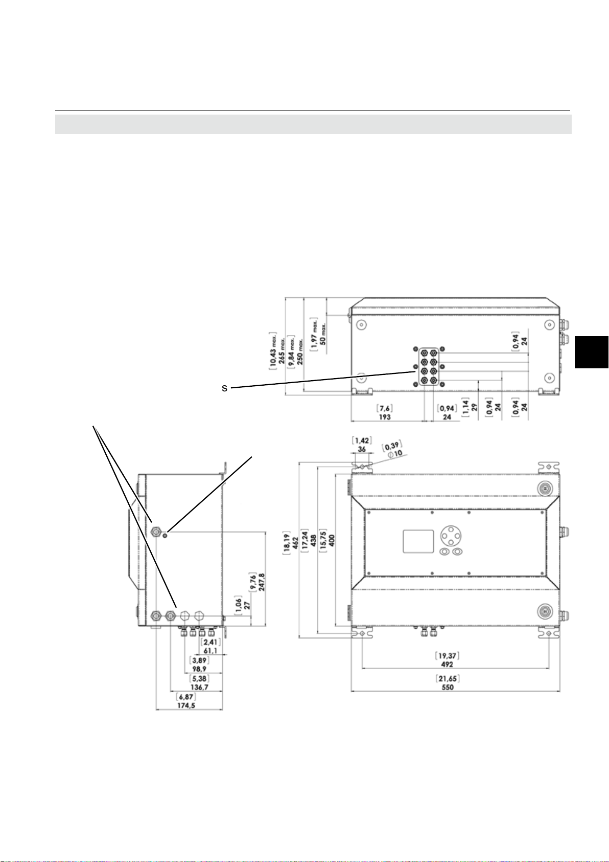
1.3 Dimensions
X-STREAM Non-Incendive
1.3 Dimensions
Gas ttings
Cable glands
All dimensions in mm
[inches in brackets]
Fig. 1-2: X-STREAM XLFN,
XEFN - dimensions
Connector
for potential
equalization
Technical Description
1
General Compliances
Electrical safety
CAN / USA
Europe
CSA-C/US, based on CAN/CSA-C22.2 No. 61010-1-04 / UL
61010-1, 2nd edition
CE, based on EN 61010-1
Electromagnetic
compatibility
Europe CE, based on EN 61326
Australia C-Tick
others NAMUR
Emerson Process Management GmbH & Co. OHG 1-5
Page 30

X-STREAM Non-Incendive
1.3 Dimensions
All dimensions in mm
[inches in brackets]
Gas ttings
Connector
for potential
equalization
Instruction Manual
HASXENE-IM-EX
03/2010
Cable glands
Fig. 1-3: X-STREAM XXFN, XDFN - dimensions
Emerson Process Management GmbH & Co. OHG1-6
Page 31

Instruction Manual
HASXENE-IM-EX
03/2010
1.4 Measurement Specications
1.4 Measurement Specications
X-STREAM Non-Incendive
Gas components
Maximum sample
gas pressure
Sample gas ow Depending on measuring principle (see related X-STREAM series instruc-
Flammable Gases must be introduced into INFALLIBLE CONTAINMENTS
ONLY, to avoid leakage into internal analyzer housing!
Such containments are provided on request.
1.5 Infallible Containments
Infallible Containments are based on connections being velded, soldered or designed as
glass-to-metal connections resp. eutectic or
similar methods. The function test for infallible
containments is performed according to the
standard EN 60079-2. Thus, it makes sure,
that no leakage may occur in the gas paths
enabling gas to enter the inner compartment
of the analyzer housing.
Non-ammable gases resp. gas mixtures; concentration does not exceed LEL
(lower explosion limit) OR
ammable gases passed into an infallible containment only!
Atmospheric pressure or <1500 hPa at normal ambient pressure, depending
on used measuring principle (see related X-STREAM series instruction
manual)
tion manual)
EXPLOSION HAZARD
X-STREAM non-incendive analyzers can be
used for measurement of ammable gases,
if the gas paths for sample gas (and ammable calibration gases) are designed as infallible
containment.
Infallible containments are availble for thermal
conductivity measurements. Consult factory
or EMERSON sales ofces for further information.
Technical Description
1
1.6 Instructions for safe use
• Open gas outlets need to end at a safe location, if releasing ammable gas above
25 % LEL.
• Signal lines need to end in safe or protected areas (e.g. in a suitable housing
type Ex e).
Emerson Process Management GmbH & Co. OHG 1-7
Page 32

X-STREAM Non-Incendive
Instruction Manual
HASXENE-IM-EX
03/2010
Emerson Process Management GmbH & Co. OHG1-8
Page 33
Instruction Manual
HASXENE-IM-EX
03/2010
X-STREAM Non-Incendive
Chapter 2
Installation
On receipt, check the packaging and its content thoroughly for damage.
Inform the carrier immediately of any damage to packaging or contents.
Keep the packaging at a safe place until unit is installed. We recommend to keep the packaging
available for returning the instrument in case of failure, because only the original packaging
ensures proper protection during transportation!
2.1 Scope of Supply
EXPLOSION HAZARD WHEN MISSING INFORMATION
Compare the content of your package with the pictures below.
Call your local sales ofce if something is missing, and DO NOT continue
to install your analyzer, until all parts are at hand!
Up to four manuals:
- X-STREAM XE or X2 series manual
- This manual addendum
*)
Analyzer
- Infallible containment manual
- Flame arrestor manual
*)
Installation
2
*)
For instruments with infallible containment
(option) only!
Fig. 2-1: X-STREAM non-incendive scope of supply
Emerson Process Management GmbH & Co. OHG 2-1
Page 34

X-STREAM Non-Incendive
EXPLOSION HAZARD AND ELECTRICAL SHOCK HAZARD
Read the corresponding sections of the analyzer instruction manual and
all addendum manuals before performing the installation !
Safe operation requires the instrument to be installed in a way not affecting
the ingress protection (IP66 / Type 4X)! Take care of the instructions for
installation.
Open covers or covers not properly closed affect the ingress protection and
result in unsafe operation! Do not operate the instrument without properly
closed covers!
Instruction Manual
HASXENE-IM-EX
03/2010
Connecting and disconnecting non-incendive X-STREAM gas analyzers is
permitted only, if the instrument and all associated power & signal lines
are de-energized!
Disregarding the safety instructions can lead to explosion, physical injury
or death!
HEAVY INSTRUMENT
X-STREAM eld housings, intended for outside and wall mounted use, weigh
between 26 kg (57 lb) and 45 kg (99 lb) depending on options installed.
Two people and/or lifting equipment is required to lift and carry these
units.
Take care to use anchors and bolts specied to be used for the weight of
the units!
Take care the wall or stand the unit is intended to be installed at is solid
and stable to support the weight!
Emerson Process Management GmbH & Co. OHG2-2
Page 35
Instruction Manual
HASXENE-IM-EX
03/2010
X-STREAM Non-Incendive
2 Installation
2.2 Abstract
Save operation of Emerson Process Management gas analyzers requires a proper
installation. Therefor all procedures that are
described in this section as well as those
of the analogous sections of the related XSTREAM series instruction manual need to
be followed strictly.
All dimensions in mm
[inches in brackets]
Gas ttings
Cable glands
Connector
for potential
equalization
2.3 Installing the Analyzer
Before installing the instrument, verify that the
installation site of the instrument is determined
adequately by means of g. 2-1 or g. 2-2.
Install the analyzer to a stand or a wall by
means of 4 mounting brackets, provided at
the instruments rear side.
It is recommended to install the analyzer in an
upright (vertical) position; other orientations
may affect the measuring results.
Installation
2
Fig. 2-2: X-STREAM XLFN, XEFN - dimensions
Emerson Process Management GmbH & Co. OHG 2-3
Page 36

X-STREAM Non-Incendive
All dimensions in mm
[inches in brackets]
Gas ttings
Connector
for potential
equalization
Instruction Manual
HASXENE-IM-EX
03/2010
2 Installation
Cable glands
Fig. 2-3: X-STREAM XXFN, XDFN - dimensions
Emerson Process Management GmbH & Co. OHG2-4
Page 37

Instruction Manual
HASXENE-IM-EX
03/2010
2.4 Connecting Gas Lines
Take care that all external gas lines are connected as described and that
they are gastight to avoid leakages! Also, gas lines for ammable gases
must end in a safe area!
Faulty connected gas lines lead to explosion hazard or even to mortal
danger!
X-STREAM Non-Incendive
2.4 Installation - Gas Lines
EXPLOSION HAZARD
Emissions may contain hydrocarbon or other toxic components (e.g.
carbon monoxide)! Carbon monoxide may cause headache, sickness,
unconsciousness and death. Don‘t breathe the emissions!
Do not confuse gas inlets and outlets. All gases supplied must be prepared
beforehand. When supplying aggressive gases, ensure that the gas lines
are not damaged.
Max. admissable pressure: 1500 hPa!
Exhaust lines must be installed to incline downwards and be unpressurized
and protected against frost, and conform to legal requirements.
More information is provided in the related X-STREAM series instruction
manual.
Installation
2
Gas connectors are accessible from the outside, on the underside of the instrument.
The number and conguration of the gas inlets and outlets depends on the use, the unit
is to be put to, and is noted on a sticker on
the underside of the instrument next to the
connectors.
Emerson Process Management GmbH & Co. OHG 2-5
To simplify installation, we recommend labelling the gas lines in accordance with these
markings. This avoids confusion, should
the analyzer need to be disconnected for
maintenance.
the gas lines, the gas connectors should be
sealed with PVC caps, to prevent pollution by
moisture, dust, etc.
Should it be necessary to open
Page 38

X-STREAM Non-Incendive
2.4 Connections of Gas Lines
Gas connections
Gas connections
max number 8
max for purging (incl. / separate) 2 incl.
material PVDF; stainless steel (opt.)
1
sizes 6/4 mm;
See gures 2-1 and 2-2 for an arrangement
of gas in- & outlets.
All connections are labeled as follows (exemplary):
⁄4"
Instruction Manual
HASXENE-IM-EX
03/2010
Fig. 2-4: Labelling of gas connectors (example)
Emerson Process Management GmbH & Co. OHG2-6
Page 39

Instruction Manual
HASXENE-IM-EX
03/2010
2.5 Electrical Installation
Failure to follow the instructions provided below may cause warranty
invalidation, property damage and personal injury or death!
Installation and connecting power and signal cables are subject to qualied
personnel only taking into account all applicable standards and legislative
requirements!
Take care of the relevant installation standards, as there are (but not limited
to) e.g. EN 60079-14 (Europe), National Electrical Code (NEC-NFPA 70; USA),
Canadian Electrical Code (CEC; Canada), IEC 60079-14 (International) and
others, and all corresponding standards.
X-STREAM Non-Incendive
2.5 Installation - Electrical
EXPLOSION AND ELECTRICAL SHOCK HAZARD
Installation
2
Installation of these instruments is subject to qualied personnel only,
familiar with the resulting potential risks! Instruments providing screw
terminals for electrical connections may require working near live part!
A power switch or circuit breaker (complying with IEC 60947.1/-3) has to be
provided in the building installation. This switch has to be installed near by
the analyzer, must be easily operator accessible, and has to be assigned
as disconnector for the analyzer.
Disconnect instruments with screw terminals from power when working at
power terminals (pull power plug or operate power switch/ circuit breaker
in building installation)!
Connecting and disconnecting non-incendive X-STREAM analyzers is
permitted only, if the instrument and all associated power & signal lines
are de-energized!
The analyzers provide a protective earth terminal. To prevent electrical shock
hazards the instruments must be connected to a protective earth. Therefore
the instruments must be connected to power by using a three wire power
cable with earth conductor!
Any interruption of the earth connector inside or outside the instrument
or disconnecting the earth terminal may cause potential electrical shock
hazzard!
The analyzers do not provide a power switch and are operable when connected to power.
Emerson Process Management GmbH & Co. OHG 2-7
Page 40

X-STREAM Non-Incendive
2.5 Installation - Electrical
EXPLOSION HAZARD WHEN ENERGIZED
Do not open instrument when energized. Ensure that external circuitry is
disconnected or de-energized before opening the instrument.
All cables (power and signal) must end (be connected) in either a safe (nonhazardous) area or in a protecting enclosure (e.g. Ex e junction box)!
The power and signal cables must be separated by a distance of minimum
1 cm (0.4 in) inside and outside the analyzer!
Instruction Manual
HASXENE-IM-EX
03/2010
EXPLOSION HAZARD
Installing and wiring this instrument must comply with all relevant national
legislative requirements and regulations.
Consider all safety instructions within this on hand manual and all associated analyzer instruction manuals!
Read the corresponding sections of the analyzer instruction manual and
all addendum manuals before performing the installation !
Disregarding the safety instructions can lead to explosion, physical injury
or death!
CRUSHING HAZARD
Take care of crushing hazard when closing the analyzer front door!
Keep out of the closing area between enclosure cover and base!
Emerson Process Management GmbH & Co. OHG2-8
Page 41

Instruction Manual
HASXENE-IM-EX
03/2010
X-STREAM Non-Incendive
2.5 Installation - Electrical
• Connect the housing to a ground or equi-
potential bonding conductor.
• Keep all cabels, entering the housing, as
short as possible.
• The cable glands are intended for cables
with an outer diameter of 7 to 12 mm [0.27
to 0.47 in]. Special adapters that allow the
mounting of thinner or multiple cables in
Signal in- and outputs
Preparation of signal cables
All signal cables are connected to screw-type
terminals located inside the housing. Access
to the internal components is gained by releasing the two (upper enclosure´s) fasteners
and opening the front panel sidewards.
All cables must be fed through cable glands
and secured with a gland nut.
one connection can be delivered on request.
• Supply terminals are intended for cables with a cross section of up to 4 mm2
[11 AWG]
• Use shielded cables only for signal lines
to ensure electromagnetic compatibility
(EMC).
Installation
2
Properly installed, the glands act as a strain
relief and guarantee EMC (electromagnetic
compatibility):
Installing cable glands with shielded cables
1. Strip the cabel
2. Expose braided
shield
3. Feed cable through
dome nut and clamping insert
4. Fold braided shield
over clamping insert
Emerson Process Management GmbH & Co. OHG 2-9
5. Make sure that braided shield overlaps
the O-r ing by 3⁄3 2“
(2 mm)
6. Push clamping insert
into body and tighten
dome nut
7. Assemble into housing
and you´re done!
Page 42

X-STREAM Non-Incendive
2.5 Installation - Electrical
Signal inputs and outputs
EXPLOSION AND ELECTRICAL SHOCK HAZARD
Verify the power supply at installation site meets the specication given on
the analyzer´s nameplate label, before installing the instrument!
Verify power cables are disconnected and/or instrument is de-energized
prior to working at the terminals!
Verify the power cord is layed with a distance of at least 1 cm (0.4 in) to any
signal cable to ensure proper insulation from signal circuits!
Instruction Manual
HASXENE-IM-EX
03/2010
The number of actually available signal outputs, and also the number of built-in modules
with screw-type terminals, varies according to
the conguration of the unit.
A maximum of three modules with 36 terminals each can be tted.
The terminals can be accessed by opening
the front panel of the instrument.
Characteristics of terminals:
Accepted wire gauge: 0.14 ... 1.5 mm2 (AWG 26 ... AWG 16),
end sleeves not required
Skinning length: 5 mm (0.2")
Thread: M2
Min. tightening torque: 0.25 Nm (2.21 in.lb)
Emerson Process Management GmbH & Co. OHG2-10
Page 43

Instruction Manual
HASXENE-IM-EX
03/2010
X-STREAM Non-Incendive
2.5 Installation - Electrical
Analog signals
Relay outputs 1 - 4
Terminals for analog signals and relais outputs
1 - 4 are located on the outer left module
(terminal block X1; g. 2-4).
Specication of analog signal outputs: 4 (0) - 20 mA; burden: RB ≤ 500 Ω
Specication of relay outputs 1-4:
Electrical specication:
Dry relay change-over contacts can be used as
NO or NC.
max. 30 VDC, 1 A, 30 W
Installation
Note!
Consider the special installation instruc-tions
in chapter 4 of the X-STREAM gas analyzer
series manuals and the notes on installing
cable glands on page 2-9!
P3.1 not used
P3.2 not used
P3.3 Output 1 (Failure), NC
P3.4 Output 1 (Failure), NO
P3.5 Output 1 (Failure), COM
P3.6 Output 2 (Maintenance Request), NC
P3.7 Output 2 (Maintenance Request), NO
P3.8 Output 2 (Maintenance Request), COM
P3.9 Output 3 (Out of Spec), NC
P3.10 Output 3 (Out of Spec), NO
P3.11 Output 3 (Out of Spec), COM
P3.12 Output 4 (Function check), NC
P4.1 Output 4 (Function check), NO
P4.2 Output 4 (Function check), COM
P4.3 not used
P4.4
P4.5
P4.6
P4.7
P4.8
P4.9
P4.10
P4.11
P4.12
P2.7 Channel 4, (+) 4 (0) - 20 mA
P2.8 Channel 4, GND
P2.9 Channel 5, (+) 4 (0) - 20 mA
P2.10 Channel 5, GND
P2.11 not used
P2.12 not used
Pin Signal
P2.1 Channel 1, (+) 4 (0) - 20 mA
P2.2 Channel 1, GND
P2.3 Channel 2, (+) 4 (0) - 20 mA
P2.4 Channel 2, GND
P2.5 Channel 3, (+) 4 (0) - 20 mA
P2.6 Channel 3, GND
**)
Conguration of relay output terminals as per standard
factory setting (NAMUR
status signals)
2
Serial Interface
*)
Relay Outputs
**)
Analog Outputs
Fig. 2-5: Terminals block X1 - analog signals and relay outputs 1-4
Emerson Process Management GmbH & Co. OHG 2-11
Page 44

X-STREAM Non-Incendive
2.5 Installation - Electrical
Serial Interface
Instruction Manual
HASXENE-IM-EX
03/2010
Specication and interface control:
Analyzer instruction manual, chapter 9
P3.10 Output 3 (Out of Spec), NO
P3.11 Output 3 (Out of Spec), COM
P3.12 Output 4 (Function check), NC
P4.1 Output 4 (Function check), NO
P4.2 Output 4 (Function check), COM
P4.3 not used
P4.4
P4.5
P4.6
P4.7
P4.8
P4.9
P4.10
P4.11
P4.12
The 9 terminals on the left (28 - 36) of the
strip next to the power connections carry the
Modbus interface signals.
X
P2.11 not used
P2.12 not used
P3.1 not used
P3.2 not used
P3.3 Output 1 (Failure), NC
P3.4 Output 1 (Failure), NO
P3.5 Output 1 (Failure), COM
P3.6 Output 2 (Maintenance Request), NC
P3.7 Output 2 (Maintenance Request), NO
P3.8 Output 2 (Maintenance Request), COM
P3.9 Output 3 (Out of Spec), NC
P2.3 Channel 2, (+) 4 (0) - 20 mA
P2.4 Channel 2, GND
P2.5 Channel 3, (+) 4 (0) - 20 mA
P2.6 Channel 3, GND
P2.7 Channel 4, (+) 4 (0) - 20 mA
P2.8 Channel 4, GND
P2.9 Channel 5, (+) 4 (0) - 20 mA
P2.10 Channel 5, GND
Pin Signal
P2.1 Channel 1, (+) 4 (0) - 20 mA
P2.2 Channel 1, GND
Serial Interface
*)
See table below
*)
Relay Outputs
Assignment of serial interface terminals
Terminal
MOD 485/
2 wire
P4.4 SER1 Common Common Common
P4.5 SER2 not used not used RXD
P4.6 SER3 not used not used TXD
P4.7 SER4 not used RXD1(+) not used
P4.8 SER5 D1(+) TXD1(+) Common
P4.9 SER6 not used not used not used
P4.10 7 not used not used not used
P4.11 8 not used RXD0(-) not used
P4.12 9 D0(-) TXD0(-) not used
Fig. 2-6: Terminals block X1 - Serial interface
MOD 485/
4 wire
**)
RS 232
Analog Outputs
Notes!
Consider the special installation instructions in chapter 4 of the X-STREAM gas
analyzer series manuals and the notes
on installing cable glands on page 2-9!
X-STREAM analyzers are classied as
DTE (Data Terminal Equipment).
The type of serial interface is marked
on a label nearby the terminals (see
sample above)
Emerson Process Management GmbH & Co. OHG2-12
Page 45

Instruction Manual
HASXENE-IM-EX
03/2010
2.5 Installation - Electrical
RJ45 Ethernet connection
If tted, the RJ45 connection is located on an
electronics board in the card cage section of
the unit (g. 2-2, pg. 2-5).
To install this connection, a cable must be
fed through the cable entry without a connector.
The connector can be wired on when the free
end has been fed into the instrument:
We recommend the VARIOSUB RJ45 QUICKON connector (PHOENIX CONTACT), which
is supplied with the unit and requires no special tools. Wiring instructions can be found
in the separate manual supplied with the
connector.
X-STREAM Non-Incendive
Installation
2
Pin 1 Pin 8
Pin no.
1 TX+
2 TX3 RX+
6 RX-
other not used
Fig. 2-7: Ethernet connector
Emerson Process Management GmbH & Co. OHG 2-13
Signal
Page 46

X-STREAM Non-Incendive
2.5 Installation - Electrical
Digital in- and outputs
Instruction Manual
HASXENE-IM-EX
03/2010
7 or 14 digital inputs
electrical
specication
electrical
specication
9 or 18 additional relay outputs
mechancial
specication
Notes!
Depending on conguration, an analyzer can
be tted with up to two of these terminal blocks
(the unit will then feature 14 digital inputs and
18 digital outputs). To aid identication, the
sockets are labelled X4.1 and X4.2.
max. 30 V, internally limited to 2.3 mA
HIGH: min. 4 V; LOW: max. 3 V
common GND
max. load. 30 V; 1 A; 30 W resistive
Dry relay change-over contacts can be
used as NO or NC
Consider the special installation instructions
in chapter 4 of the X-STREAM gas analyzer
series manuals and the notes on installing
cable glands on page 2-9!
P4
P3.5 Output 5
P3.6 Output 6
P3.7 Output 7
P3.8 GND for inputs 1-7
P3.9 unused
P3.10 Output 5, NC
P3.11 Output 5, NO
P3.12 Output 5, COM
P4.1 Output 6, NC
P4.2 Output 6, NO
P4.3 Output 6, COM
P4.4 Output 7, NC
P4.5 Output 7, NO
P4.6 Output 7, COM
P4.7 Output 8, NC
P4.8 Output 8, NO
P4.9 Output 8, COM
P4.10 Output 9, NC
P4.11 Output 9, NO
P4.12 Output 9, COM
P2.1 Output 10, NC
P2.2 Output 10, NO
P2.3 Output 10, COM
P2.4 Output 11, NC
P2.5 Output 11, NO
P2.6 Output 11, COM
P2.7 Output 12, NC
P2.8 Output 12, NO
P2.9 Output 12, COM
P2.10 Output 13, NC
P2.11 Output 13, NO
P2.12 Output 13, COM
Digital outputs
Digital inputs
Fig. 2-8: Terminals block X4.1 and X4.2 - digital inputs and outputs
P3.4 Output 4
Note!
Pin Signal
P3.1 Output 1
P3.2 Output 2
P3.3 Output 3
The conguration illustrated here is that of the rst
adapter, labelled X4.1.
Inputs 8-14 and outputs
14-22, if available, are on
the second adapter X4.2,
see label above).
Emerson Process Management GmbH & Co. OHG2-14
Page 47

Instruction Manual
HASXENE-IM-EX
03/2010
X-STREAM Non-Incendive
2.5 Installation - Electrical
Analog inputs
(XEFN, XDFN only!)
0 - 1 V, 0 - 10 V (software selectable) R
optional (requires to t wire bridges, see gure):
2 analog inputs
4 (0) - 20 mA ; R
= 50Ω
in
optically isolated from analyzer GND
protected against overload up to
Note!
Consider the special installation instructions
in chapter 4 of the X-STREAM gas analyzer
series manuals and the notes on installing
cable glands on page 2-9!
= 100 kΩ
in
±15 V or ±20 mA
Installation
2
2
P4.9 Input 2 high (+)
P4.10 Input 2 high (+)
P4.11 Input 2 low (-)
P4.12 Input 2 low (-)
P4.1 BR 1 t a wire bridge here to apply analog
P4.2 BR 1 signal in current mode to input 1
P4.3 Input 1 high (+)
P4.4 Input 1 high (+)
P4.5 Input 1 low (-)
P4.6 Input 1 low (-)
P4.7 BR 2 t a wire bridge here to apply analog
P4.8 BR 2 signal in current mode to input 2
P2.12 not used
Pin Signal
P2.1 not used
P2.2 not used
P2.3 not used
P2.4 not used
P2.5 not used
P2.6 not used
P2.7 not used
P2.8 not used
P2.9 not used
P2.10 not used
P2.11 not used
1
{
{
1 Screw-type terminals
2 Reserved for future use
}
IN2
Mode
Analog Inputs
}
IN1
Mode
Fig. 2-9: Terminals block X5 - analog input signals
Emerson Process Management GmbH & Co. OHG 2-15
Page 48
Instruction Manual
X-STREAM Non-Incendive
2.5 Installation - Electrical
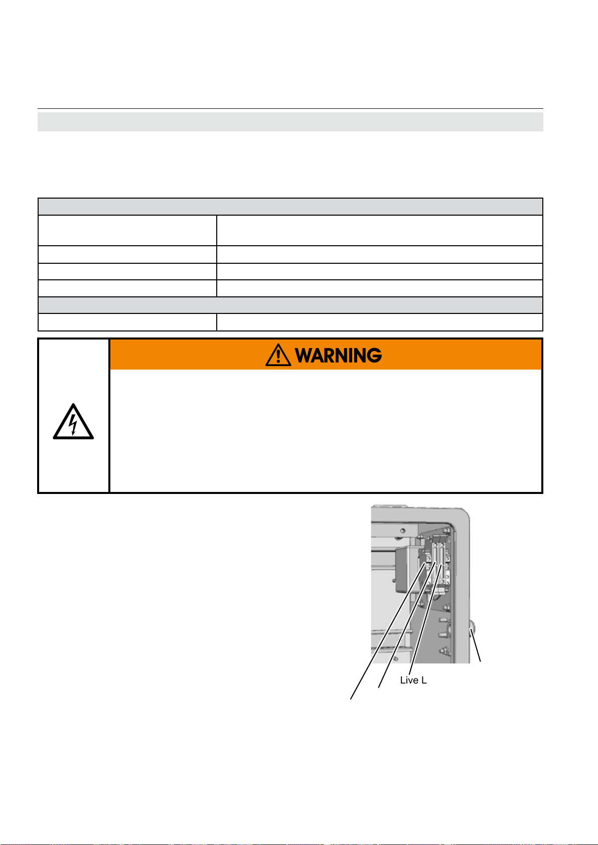
Connecting the power cord
The power cord is connected to screw-type terminals located inside the housing.
Terminals
Power Supply
Recommended cross section min. 1,5 mm²
Skinning length: 8 mm (0.315"); no need to use wire end sleeves
Tightening torque: min. 0.5 Nm (4.4 in.lb)
Input Fuses
Specication AC 230 V / T 4 A / 5x20 mm
Screw type terminals with integral fues holders
max. 4 mm² (12 AWG)
HASXENE-IM-EX
03/2010
ELECTRICAL SHOCK HAZARD
Verify the power supply at installation site meets the specication given on
the analyzer´s nameplate label, before installing the instrument!
Verify power cables are disconnected and/or instrument is de-energized
prior to working at the terminals!
Verify the power cord is layed with a distance of at least 1 cm (0.5“) to any
signal cable to ensure proper insulation from signal circuits!
Feed the power cable through the cable
gland at the instrument´s right side and strip
the outer insulation. Strip the individual wires
and connect to the terminals (a label is located next to the terminals on the mains lter
housing).
Finally, tighten the outer dome nut to secure
the power cable.
Earth PE
Live L
Neutral N
Power supply
cable gland
Fig. 2-10: Power terminals
Emerson Process Management GmbH & Co. OHG2-16
Page 49

Instruction Manual
HASXENE-IM-EX
03/2010
2.5 Installation - Electrical
EXPLOSION HAZARD
Before completing the electrical connection of the instrument, verify cables
are inserted and connected in correct manner!
Ensure the earthing conductor (protective earth; PE) is connected!
When all connections are correctly made and
checked,
• close the front panel and secure it with
the fasteners.
2.5.1 External Equipotential Bonding Connector
X-STREAM Non-Incendive
Installation
2
The instrument provides a thread (metric M5)
right beside the power cable inlet, to connect
an equipotential bonding conductor.
Take care to use a cable for the
equipotential connection with
at least the same cross section as provided by the power
cable!
The installation has to comply with sound engineering practice (g. 2-10). Take measures
to avoid contact corrosion!
2
4
1 Lock washer
2 Ring terminal
5
3 Flat washer
4 Lock washer
5 Screw M5
Maximum depth of the enclosure thread is 6 mm!
Take care to use a screw of a
proper length, to ensure the
ring terminal (item 2) is properly
xed!
Thread for connecting the equipotential
bonding conductor
3
1
Fig. 2-11: Equipotential bonding conductor terminal
Emerson Process Management GmbH & Co. OHG 2-17
Page 50

X-STREAM Non-Incendive
Instruction Manual
HASXENE-IM-EX
03/2010
Emerson Process Management GmbH & Co. OHG2-18
Page 51

Instruction Manual
HASXENE-IM-EX
03/2010
Chapter 3
Startup
EXPLOSION HAZARD
Startup, operation and service must not be performed before reading and
understanding all instructions!
Especially all warnings in this, and all associated manuals have to be
considered!
3.1 Final Check
Ensure that the analyzer has been installed
according to the descriptions in chapter 2,
and that all covers and doors are closed and
fastened.
All unused cable connections need to be closed
with the provided permissible sealing plugs
(part # ETC00791; Fig. 3-1)
Unused openings for cable connections in
the housing need to be closed with a special
screw (part # ETC00790; Fig. 3-2).
X-STREAM Non-Incendive
Startup
3
Fig. 3-1: Sealing plug for cable connections Fig. 3-2: Hexagon socket screw as sealing
plug for unused cable inlet openings
EXPLOSION HAZARD
Use the above mentioned approved components only!
Emerson Process Management GmbH & Co. OHG 3-1
Page 52

X-STREAM Non-Incendive
OPERATION AT LOW TEMPERATURES
When operating an instrument at temperatures below 0 °C (32 °F), do
NOT apply gas nor operate the internal pump before the warmup time has
elapsed!
Violation may result in condensation inside the gas paths or damaged pump
diaphragm!
Consider the instructions in the related X-STREAM series manual!
Instruction Manual
HASXENE-IM-EX
03/2010
3 Startup
3.2 Switching On
After all safety aspects are followed and
checked, the instrument may be powered and
operated according the instructions given in
the X-STREAM series instruction manuals.
Read this manual for detailled information
about software, parameter settings and
more.
Emerson Process Management GmbH & Co. OHG3-2
Page 53

Instruction Manual
HASXENE-IM-EX
03/2010
X-STREAM Non-Incendive
Chapter 4
Service and Maintenance
Note!
This chapter deals with service and maintenance procedures related to explosion protection only!
More detailled instructions about servicing and maintaining general purpose components of
X-STREAM gas analyzers are subject of the X-STREAM gas analyzer instruction manual.
EXPLOSION HAZARD
Inspection, maintenance and service must be carried out considering
all related standards e.g. for „Inspection and maintenance of electrical
installations in hazardous areas“ or „Equipment repair, overhaul and
reclamation“.
EXPLOSION HAZARD BY REPLACEMENT PARTS
Service or replacement of safety related components or requiring to open
the instrument are permitted only if no hazardous atmosphere is present
and both the instrument and connected circuitry are de-energized!
Depending on the local regulation this may require a competent hot work
supervisor to issue a hot work permit.
EXPLOSION HAZARD BY UNAUTHORIZED REPLACEMENTS
After maintenance or replacement of parts concerning explosion protection
an authority on explosion protection has to verify that the analyzer still meets
the requirements for explosion protection before it is switched on again.
Parts essential for explosion protection must not be repaired, they must be
replaced if defective!
Maintenance
4
The authority has to issue a certicate for this and/or attach a test label to
the equipment before startup after maintenance or replacement of parts.
Emerson Process Management GmbH & Co. OHG 4-1
Page 54

X-STREAM Non-Incendive
EXPLOSION HAZARD BY REPLACED PARTS
Replacement of parts found defective is permitted only by using original
parts!
Any addition, substitution, or replacement of components installed on or
in this device, must be certied to meet the hazardous area classication
that the device was certied to prior to any such component addition,
substitution, or replacement. In addition, the installation of such device or
devices must meet the requirements specied and dened by the hazardous
area classication of the unmodied device.
Any modications to the device, not authorized by Emerson Process
Management will void the product certication(s).
Instruction Manual
HASXENE-IM-EX
03/2010
4 Maintenance
Violation voids the approvals and may cause explosions!
EXPLOSION HAZARD BY MODIFICATION
Modications affecting the integrity of type of protection (e.g. afxing
additional threads) are NOT PERMITTED!
Violation may cause an explosion and/or personal injury or death!
HAZARDS BY GASES
When measuring ammable or toxic gases, it is recommended to purge
the system with air or an inert gas, e.g. nitrogen, prior to opening the gas
paths.
Violation may cause an explosion and/or personal injury or death!
Emerson Process Management GmbH & Co. OHG4-2
Page 55

Instruction Manual
HASXENE-IM-EX
03/2010
4.1 Maintenance Instructions
X-STREAM Non-Incendive
4 Maintenance
To assure instrument performance and safety,
the analyzer has to be checked regularly, at
least once a year.
During maintenance especially parts found relevant for explosion protection have to be taken
into account. For non-incendive X-STREAM
gas analyzers this particularly includes the
enclosure and the corresponding gaskets.
Enclosure and gaskets need to be checked for
damages, and gaskets must be sufciently tight
leakage test, page 4-4).
(
During maintenance, the optional gas samp-
ling pump has to be evaluated for grinding
moving parts, creating sparks.
Internal connectors have to be regarded
accordingly. They need to be xed, to not
produce sparks during operation.
By visual inspection of the interior of the analyzer, especially the electrical components,
it must be veried that components are not
overloaded. Overloaded components may
become hot, and thus become a source of
ignition! An indicator for overload may be
discoloration.
Parts found a potential risk of
hot spots, arc or sparcs must
be replaced!
The user/owner has to take responsibility to modify the maintenance interval regarding the
conditions at site
gases or ambient atmosphere on
material in contact with sample/
calibration gas or which are relevant for
[e.g. enclosure sealing]).
explosion protection
(inuence of
Maintenance
4
4.2 Gas Paths
Detailled information about maintenance,
replacement of components and performing
a gas paths leakage test are available in the
associated X-STREAM series general instruction manual.
Emerson Process Management GmbH & Co. OHG 4-3
Page 56

X-STREAM Non-Incendive
4 Maintenance
4.3 Checking Modied or Repaired Analyzers
Instruction Manual
HASXENE-IM-EX
03/2010
Modications on non-incendive X-STREAM
gas analyzers which inuence the integrity
of protection type or analyzer temperature
are permissible only, if the modied analyzer
are inspected by a licensed test laboratory,
or if an authorized expert has evaluated the
modications.
4.3.1 Enclosure Leakage Test
4.3.1.1 Preparation
Required Tools:
• Pressure gauge with a measuring range
of 50 to 100 mbar (0.7 to 1.5 psig; resolution of 0.1 mbar/ 0.0015 psig).
Flow meter with a measuring range of 5 to
•
10 l/min;
resolution of
0.1 l/min.
• Span gas: Instrumental air or nitrogen; pressure reduced to 1.500 mbar
(22 psig).
• Pressure regulator to reduce pressure to
25 mbar (0.4 psig)
• Equipment for ow control
• 1 plug to shut off the gas outlet
(size: 6 mm / 1⁄4“)
In case of repair inuencing the protection
type, the repaired parts should be drawn to
suitable check routines and must be controlled. These inspections need not necessarily to be carried out by EMERSON Process
Management, but can also be performed by
local trained service personnel.
Local regulations may require
to apply additional markings to
repaired equipment in hazardous areas!
To run the test procedure, the following preparations have to be encountered:
• Disconnect from power, or de-energize
the analyzer.
• Disconnect containment system ttings
from external gas pipes.
• Disconnect one containment system gas
tting inside the analyzer and close the
other tting.
Note:
Now it need to be possible to pressurize
the housing supplying an external gas
(e.g. compressed air) to the gas inlet.
• Supply compressed air from an external
source as described in section 4.3.1.2 on
the following page.
The compressed air must be
dry and free from dust, oil and
corrosive components!
Emerson Process Management GmbH & Co. OHG4-4
Page 57

Instruction Manual
HASXENE-IM-EX
03/2010
X-STREAM Non-Incendive
4 Maintenance
Fig. 4-1: Assembly for check routines
4.3.1.2 Run Leakage Test
The housing needs to be controlled on leakages with a pressure of 25 mbar (0.4 psig). The
following steps have to be provided:
Modify like described on section 4.3.1.1
•
• Supply a pressure of 25 mbar to the ana-
lyzer housing and take care of the ow
meter display.
The test is passed, if the measured value
does not exceed the following max. value:
Permissible ow: 3 l/min max.
Maintenance
4
4.3.1.3 Startup after Test Procedure
All modications described in section 4.3.1.1
have to be cancelled.
Especially the gas ttings‘ tight assemblies
.
need to be checked.
Emerson Process Management GmbH & Co. OHG 4-5
Page 58
X-STREAM Non-Incendive
4 Replacement of Parts
4.4 Replacement of Components
EXPLOSION HAZARD BY REPLACEMENT OF PARTS
Replacement of parts found defective is permitted only by using original
parts!
Violation voids the approvals and may cause explosions!
Parts, important for the safety of non-incendive X-STREAM gas analyzers:
Instruction Manual
HASXENE-IM-EX
03/2010
Optional internal gas sampling pump
Type: 113.095.100.0
Supplier: ASF Thomas, WISA
Spare part #: 90002983
Relays (soldered on circuit boards,
not to be replaced by the user.
These components must not be exchanged
individually!) Several types and suppliers
All internal connections and
screw terminals Several types and suppliers
Fuses Specication: T 6.3 A; 250V
Type: 215 (5x20 mm)
Supplier: Wickmann / Littlefuse
Spare part #: ETC00192
Power terminals and fuse holder
Type: UK 5 - HESI
Supplier: Phoenix
Spare part #: ETC00941
Emerson Process Management GmbH & Co. OHG4-6
Page 59

Instruction Manual
HASXENE-IM-EX
03/2010
4 Replacement of Parts
Cable glands
Type: HSK-M-EMV-Ex-Met
Supplier: Hummel Elektrotechnik
II 2G EEx e II
Spare part #: ETC00788
Internal battery
Type: CR2032; 3Vdc; 230 mAh
Primary Lithium Button Cell
Supplier: Varta Batteries
X-STREAM Non-Incendive
Maintenance
4
Emerson Process Management GmbH & Co. OHG 4-7
Page 60

X-STREAM Non-Incendive
Instruction Manual
HASXENE-IM-EX
03/2010
Emerson Process Management GmbH & Co. OHG4-8
Page 61

Instruction Manual
HASXENE-IM-EX
03/2010
X-STREAM Non-Incendive
Appendix
This chapter contains:
EC Declarations of Conformity A.1, page A-2
ATEX Manufacturer‘s Declaration A.2, page A-3
ATEX Certicate of Conformity A.3, page A-4
CSA Certicate of Compliance A.4, page A-7
Block diagrams A.5, page A-14
Assignment of Terminals and Sockets A.6, page A-31
Appendix
A
Emerson Process Management GmbH & Co. OHG A-1
Page 62

X-STREAM Non-Incendive
A.1 EC Declaration of Conformity
A.1 EC Declarations of Conformity
Instruction Manual
HASXENE-IM-EX
03/2010
Emerson Process Management GmbH & Co. OHGA-2
Page 63

Instruction Manual
HASXENE-IM-EX
03/2010
A.2 Manufacturer‘s Declaration
A.2 ATEX Manufacturer‘s Declarations
X-STREAM Non-Incendive
Appendix
A
Emerson Process Management GmbH & Co. OHG A-3
Page 64

X-STREAM Ex d
A.3 EC Certicate of Conformity
A.3 EC Certicate of Conformity
Instruction Manual
HASXEDE-IM-EX
03/2010
Emerson Process Management GmbH & Co. OHGA-4
Page 65

Instruction Manual
HASXEDE-IM-EX
03/2010
X-STREAM Ex d
A.3 EC Certicate of Conformity
Appendix
A
Emerson Process Management GmbH & Co. OHG A-5
Page 66

X-STREAM Ex d
Instruction Manual
HASXEDE-IM-EX
03/2010
A.3 EC Certicate of Conformity
Emerson Process Management GmbH & Co. OHGA-6
Page 67

Instruction Manual
HASXEDE-IM-EX
03/2010
A.4 CSA Certicate of Compliance
A.4 CSA Certicate of Compliance
Certificate of Compliance
X-STREAM Ex d
Certificate:
Project:
Issued to: Emerson Process Management
1714037 (LR 105173)
2280890
GmbH & Co. OHG
Industriestrasse 1
Hasselroth, 63594
Germany
Attention: Uwe Schmidt
Master Contract:
Date Issued:
185562
2010/03/05
The products listed below are eligible to bear the CSA
Mark shown with adjacent indicators 'C' and 'US' for
Canada and US or with adjacent indicator 'US' for
US only or without either indicator for Canada only.
Amy Pura E.I.T.
Issued by:
PRODUCTS
CLASS 2258 82
CLASS 2258 02
CLASS 8721 85
CLASS 8721 05
CLASS 8721 05 - LABORATORY ELECTRICAL EQUIPMENT
CLASS 8721 85 - ELECTRICAL EQUIPMENT FOR LABORATORY USE (Certified to U.S. Standards)
Gas analyzer, Model: X-STREAM, rated 100-240Vac, 50/60 Hz, 3 - 1.5A, Class I, Pollution Degree II.
• X-STREAM F (XF) or X-STREAM (X2F, XLF) or X-STREAM Enhanced Field Housing Gas
Analyzer (XEF): Wall mounting with field wiring terminals, for outdoor use type 4 & IP66 and display;
• X-STREAM GP (XGP): Table Top or Rack Mount with field wiring terminals for indoor use;
• X-STREAM GPS (XGPS): Table Top or Rack Mount with appliance inlet for indoor use with or without
display;
- PROCESS CONTROL EQUIPMENT - For Hazardous Locations Certified to US Standards
- PROCESS CONTROL EQUIPMENT - For Hazardous Locations
- ELECTRICAL EQUIPMENT FOR LABORATORY USE - Certified to US
Standards
- LABORATORY EQUIPMENT - Electrical
Amy Pura E.I.T.
Appendix
A
DQD 507 Rev. 2009-09-01
Emerson Process Management GmbH & Co. OHG A-7
Page 68

X-STREAM Ex d
Instruction Manual
HASXEDE-IM-EX
03/2010
A.4 CSA Certicate of Compliance
Certificate:
Project:
• X-STREAM (X2GP) or X-STREAM Enhanced (XEGP) General Purpose Gas Analyzer: Table Top or
Rack Mount with appliance inlet for indoor use and display (optional with field wiring terminals for indoor
use);
• X-STREAM Gas Analyzer Core (X2CA) Table Top or Rack Mount with appliance inlet for indoor use and
no display (optional with field wiring terminals for indoor use);
Gas analyzer, Model: X-STREAM, rated 100-240Vac, 50/60 Hz, 5.5 - 3A, Class I, Pollution Degree II.
• X-STREAM (XXF) or X-STREAM Enhanced Field Housing Gas Analyzer (XDF): Wall mounting with
field wiring terminals, for outdoor use type 4 & IP66 and display;
Gas analyzer, Model: X-STREAM, rated 24Vdc, 2.5A, Class I, Pollution Degree II.
• X-STREAM (X2GC)or X-STREAM Enhanced (XEGC)General Purpose Compact Gas Analyzer Table
Top or Rack Mount with 24Vdc in connector and display;
• X-STREAM Compact Gas Analyzer Core (X2CC): Table Top or Rack Mount with 24Vdc in
Conditions of Acceptability
- For the X-STREAM Models XGP, XGPS, X2GP, X2CA and XEGP the equipment is supplied with an
approved power supply cord set or power supply cord with plug that is acceptable to the authorities in the
country where the equipment is to be used. Units supplied without a power cord and that are not permanently
connected are considered as component. Component-type units must be provided with a Fire, Mechanical and
Electrical enclosure and must be re-evaluated by CSA.
- The plug/connector is used as the disconnected device. The switch for X2GP/X2CA/XEGP is not considered
the disconnect device. All units must be provided with a disconnect device.
CLASS 2258-02 PROCESS CONTROL EQUIPMENT – For Hazardous Locations
CLASS 2258-82 PROCESS CONTROL EQUIPMENT – For Hazardous Locations – Certified to U.S.
Standards.
X-Stream FD (XFD): Flameproof for Hazardous Locations
Class I, Zone 1, Ex d IIB+H2, T3
Class I, Zone 1, AEx d IIB+H2, T3
Gas analyzer, Model: X-Stream, rated 100-240Vac, 50/60 Hz, 2–1 A. Class I, Pollution Degree II; Type 4 &
IP66
Ambient Temperature Range: -30°C to +50°C Maximum internal case pressure = 110kpa
XFD-abcdefghijklmnop
1714037 (LR 105173)
2280890
Master Contract:
Date Issued:
185562
2010/03/05
DQD 507 Rev. 2009-09-01
Emerson Process Management GmbH & Co. OHGA-8
Page 69

Instruction Manual
HASXEDE-IM-EX
03/2010
X-STREAM Ex d
A.4 CSA Certicate of Compliance
Certificate:
Project:
a = Language: A, B, C, D or E
b = Ambient Conditions: 1, 2, 3, 4, 5 or 6
c = Instrument: 1, 2, 3, 4, 5, 6 or 7
d = Bench 1: any combination of 2 or 3 alpha-numeric characters
e = Bench 1 – Special Linearization or Calibration: 0, 1, 2, 3, 4 or 5
f = Bench 2: any combination of 2 or 3 alpha-numeric characters
g = Bench 2 – Special Linearization or Calibration: 0, 1, 2, 3, 4 or 5
h = Enclosure: 1, 2, 3, 4, 5 or 6
i = Hazardous Area Options and Special Approvals: B or D
B = CSA Certification
D = CSA Certification with a Breathing Device for Venting (Same Device as option “p”)
j = Input/Output Options: 1, 2, 5 or 6
k = Communication Interface: A, B, C or D
l = Sample Handling: 0, 1, 3, 5 or 7
m = Gas Path Sensors: 0, 1, 2, 3, 4 or 5
n = Gas Path Tubing: A, B, C, D or E
o = Gas Path Fittings: 3, 4, 5 or 6
p = Flame Arrestors: 2, 3, 4, 5, 6, 7 or 8
X-Stream FD (X2FD): Flameproof for Hazardous Locations
Class I, Zone 1, Ex d IIB+H2, T3
Class I, Zone 1, AEx d IIB+H2, T3
Gas analyzer , Model: X-Stream, rated 100-240Vac, 50/60 Hz, 3 - 1.5A, Class I, Pollution Degree II; Ambient
Temperature Range: -30°C to +50°C
X-Stream FD (X2FD) has same electronics as the X-STREAM General Purpose Gas Analyzer (X2GP) with
new Hazardous Locations Enclosure.
1714037 (LR 105173)
2280890
Master Contract:
Date Issued:
185562
2010/03/05
Appendix
A
DQD 507 Rev. 2009-09-01
Emerson Process Management GmbH & Co. OHG A-9
Page 70

X-STREAM Ex d
Instruction Manual
HASXEDE-IM-EX
03/2010
A.4 CSA Certicate of Compliance
Certificate:
Project:
X2FD-abcdefghijklmnopqrstuv
a = Language: A, B, C, D, E or F
b = Ambient Conditions: 1, 2, 3, 4, 5 or 6
c = Instrument: 01, 02, 03, 04, 05, 06, 07, 08, 09, 10, 11, 12, 13, 14 or 15
d = Bench 1: any combination of 2 or 3 alpha-numeric characters
e = Bench 1 – Special Linearization or Calibration: 0, 1, 2, 3, 4, 5, A, B, C or D
f = Bench 2: any combination of 2 or 3 alpha-numeric characters
g = Bench 2 – Special Linearization or Calibration: 0, 1, 2, 3, 4, 5, A, B, C or D
h = Bench 3: any combination of 2 or 3 alpha-numeric characters
i = Bench 3 – Special Linearization or Calibration: 0, 1, 2, 3, 4, 5, A, B, C or D
j = Bench 4: any combination of 2 or 3 alpha-numeric characters
k = Bench 4 – Special Linearization or Calibration: 0, 1, 2, 3, 4, 5, A, B, C or D
l = Enclosure: 1, 2, 3, 4, 5 or 6
m = Hazardous Area Options and Special Approvals: B or D
B = CSA Certification
D = CSA Certification with a Breathing Device for Venting (Same Device as option “v”)
n = Analog Outputs: 1, 2, 3 or 4
o = Digital Inputs/Relay Outputs: 0, 1 or 2
p = Communication Interface: 0, A, B, C or D
q = Spare: 0
r = Sample Handling: 0, 1, 2, 3, 4, 5 or 6
s = Gas Path Sensors: 0, 1, 2, 3, 4, 5, 6, 7 or 8
t = Gas Path Tubing: A, B, C, D, E, F, G, H or I
u = Gas Path Fittings: E, F, G, H, I, J, K or L
1714037 (LR 105173)
2280890
Master Contract:
Date Issued:
185562
2010/03/05
DQD 507 Rev. 2009-09-01
Emerson Process Management GmbH & Co. OHGA-10
Page 71

Instruction Manual
HASXEDE-IM-EX
03/2010
X-STREAM Ex d
A.4 CSA Certicate of Compliance
Certificate:
Project:
v = Flame Arrestors: 2, 3, 4, 5, 6, 7 or 8
X-STREAM FD (XEFD): Flameproof for Hazardous Locations
Class I, Zone 1, Ex d IIB+H2, T3
Class I, Zone 1, AEx d IIB+H2, T3
Gas analyzer , Model: X-STREAM, rated 100-240Vac, 50/60 Hz, 3 - 1.5A, Class I, Pollution Degree II;
Ambient Temperature Range: -30°C to +50°C
X-STREAM FD Enhanced (XEFD) has same electronics as the X-STREAM Enhanced General Purpose Gas
Analyzer (XEF) with same Hazardous Locations Enclosure as X-STREAM X2FD.
XEFD-abcdefghijklmnopqrstuv
a = Language: A, B, C, D, E, F or G
b = Ambient Conditions: 1 or 4
c = Instrument: 01, 02, 03, 04, 05, 06, 07, 08, 09, 10, 11, 12, 13, 14 or 15
d = Bench 1: any combination of 2 or 3 alpha-numeric characters
e = Bench 1 – Special Linearization or Calibration: 0, 1, 2, 3, 4, 5, A, B, C or D
f = Bench 2: any combination of 2 or 3 alpha-numeric characters
g = Bench 2 – Special Linearization or Calibration: 0, 1, 2, 3, 4, 5, A, B, C or D
h = Bench 3: any combination of 2 or 3 alpha-numeric characters
i = Bench 3 – Special Linearization or Calibration: 0, 1, 2, 3, 4, 5, A, B, C or D
j = Bench 4: any combination of 2 or 3 alpha-numeric characters
k = Bench 4 – Special Linearization or Calibration: 0, 1, 2, 3, 4, 5, A, B, C or D
l = Enclosure: 1, 2, 3 or 4
m = Hazardous Area Options and Special Approvals: B or D
B = CSA Certification
D = CSA Certification with a Breathing Device for Venting (Same Device as option “v”)
1714037 (LR 105173)
2280890
Master Contract:
Date Issued:
185562
2010/03/05
Appendix
A
DQD 507 Rev. 2009-09-01
Emerson Process Management GmbH & Co. OHG A-11
Page 72

X-STREAM Ex d
Instruction Manual
HASXEDE-IM-EX
03/2010
A.4 CSA Certicate of Compliance
Certificate:
Project:
n = Analog Outputs: 1, 2, 3 or 4
o = Digital Inputs/Relay Outputs/Analog Inputs: 0, 1, 2, 5 or A
p = Communication Interface: 0, A or B
q = Advanced Software capabilities: 0, 1, 2 or 3
r = Sample Handling: 0, 1, 2, 3, 4, 5 or 6
s = Gas Path Sensors: 0, 1, 3, 5, 7 or 9
t = Gas Path Tubing: E, F, G, H, I, J, K or L
u = Gas Path Fittings: E, F, G, H, I, J, K or L
v = Flame Arrestors: 2, 3, 4, 5, 6, 7 or 8
X-STREAM FN (X2FN, XLFN, XXFN, XEFN, XDFN): Non-Incendive for Hazardous Locations
Class 1 Zone 2 Ex nAC IIC T4
Class 1 Zone 2 AEx nAC IIC T4
Class I Div 2 Groups ABCD
-20 °C to +50 °C IP66 Enclosure Type 4X
Gas analyzer, Model: X-STREAM, rated 100-240Vac, 50/60 Hz, 3 - 1.5A, Class I, Pollution Degree II.
• X-STREAM Field Housing Gas Analyzer (X2FN):
• X-STREAM (XLFN) or X-STREAM Enhanced (XEFN)Field Housing Gas Analyzer:
Gas analyzer, Model: X-STREAM, rated 100-240Vac, 50/60 Hz, 5.5 - 3A, Class I, Pollution Degree II
• X-STREAM (XXFN) or X-STREAM Enhanced Dual (XDFN) Field Housing Gas Analyzer:
APPLICABLE REQUIREMENTS
CAN/CSA-C22.2 No. 61010-1-04 - Safety Requirements for Electrical Equipment for
Measurement, Control, and Laboratory Use, Part 1: General Requirements
UL Std No. 61010-1, 2nd Edition. - Safety Requirements for Electrical Equipment for
Measurement, Control, and Laboratory Use, Part 1: General Requirements
1714037 (LR 105173)
2280890
Master Contract:
Date Issued:
185562
2010/03/05
DQD 507 Rev. 2009-09-01
Emerson Process Management GmbH & Co. OHGA-12
Page 73

Instruction Manual
HASXEDE-IM-EX
03/2010
X-STREAM Ex d
A.4 CSA Certicate of Compliance
Certificate:
Project:
CAN/CSA-E60079-0:02 (R2006) - Electric Apparatus for Explosive Gas Atmospheres, Part 0:
General Requirements
CAN/CSA-E60079-1:02 (R2006) - Electric Apparatus for Explosive Gas Atmospheres, Part 1:
Construction and Verification Test of Flameproof Enclosures of Electrical Apparatus “d”
CAN/CSA-E60079-15:02 (R2006) - Electric Apparatus for Explosive Gas Atmospheres, Part 15:
Type of protection "n"
CSA C22.2 No 213-M1987 - Non-Incendive Electrical Equipment for Use in Class
I,Division 2 Hazardous Locations
CAN/CSA-C22.2 No. 94-M91 (R2001) - Special Purpose Enclosures
CAN/CSA C22.2 No. 60529:05 - Degrees of protection provided by enclosure (IP Code)
ANSI/ISA-12.00.01-2002 (IEC 60079-0 Mod) - Electric Apparatus for Use in Class I, Zones 0, 1 & 2
Hazardous (Classified) Locations: General Requirements
ANSI/ISA-12.22.01-2002 (IEC 60079-1 Mod) - Electric Apparatus for Use in Class I, Zones 1 Hazardous
(Classified) Locations Type of Protection – Flameproof “d”
UL 60079-15:2009 - Electric Apparatus for Explosive Gas Atmospheres, Part 15:
Construction, Test and Marking of Type of Protection ’n’ Electrical Apparatus
IEC 60529 Edition 2.1-2001-02 - Degrees of protection provided by enclosure (IP Code)
UL 50 11th ed - Enclosures for Electrical Equipment
ISA 12.12.01-2007 - Nonincendive Electrical Equipment for Use in Class I and II,
Division 2 and Class III, Divisions 1 and 2 Hazardous (Classified) Locations
1714037 (LR 105173)
2280890
Master Contract:
Date Issued:
185562
2010/03/05
Appendix
A
DQD 507 Rev. 2009-09-01
Emerson Process Management GmbH & Co. OHG A-13
Page 74

X-STREAM Non-Incendive
A.5 Block Diagrams
A.5 Block diagrams
A.5.1 XLFN ,
XXFN
Instruction Manual
HASXENE-IM-EX
03/2010
Emerson Process Management GmbH & Co. OHGA-14
Page 75

Instruction Manual
HASXENE-IM-EX
03/2010
X-STREAM Non-Incendive
A.5 Block Diagrams
Appendix
A
Emerson Process Management GmbH & Co. OHG A-15
Page 76

X-STREAM Non-Incendive
A.5 Block Diagrams
Instruction Manual
HASXENE-IM-EX
03/2010
Emerson Process Management GmbH & Co. OHGA-16
Page 77

Instruction Manual
HASXENE-IM-EX
03/2010
X-STREAM Non-Incendive
A.5 Block Diagrams
Appendix
A
Emerson Process Management GmbH & Co. OHG A-17
Page 78

X-STREAM Non-Incendive
A.5 Block Diagrams
Instruction Manual
HASXENE-IM-EX
03/2010
Emerson Process Management GmbH & Co. OHGA-18
Page 79

Instruction Manual
HASXENE-IM-EX
03/2010
X-STREAM Non-Incendive
A.5 Block Diagrams
Appendix
A
Emerson Process Management GmbH & Co. OHG A-19
Page 80

X-STREAM Non-Incendive
A.5 Block Diagrams
Instruction Manual
HASXENE-IM-EX
03/2010
Emerson Process Management GmbH & Co. OHGA-20
Page 81

Instruction Manual
HASXENE-IM-EX
03/2010
A.5.2 XEFN, XDFN
X-STREAM Non-Incendive
A.5 Block Diagrams
X-STREAM Version
Appendix
A
Emerson Process Management GmbH & Co. OHG A-21
Page 82

X-STREAM Non-Incendive
A.5 Block Diagrams
Instruction Manual
HASXENE-IM-EX
03/2010
Emerson Process Management GmbH & Co. OHGA-22
Page 83

Instruction Manual
HASXENE-IM-EX
03/2010
X-STREAM Non-Incendive
A.5 Block Diagrams
Appendix
A
Emerson Process Management GmbH & Co. OHG A-23
Page 84

X-STREAM Non-Incendive
A.5 Block Diagrams
Instruction Manual
HASXENE-IM-EX
03/2010
Emerson Process Management GmbH & Co. OHGA-24
Page 85

Instruction Manual
HASXENE-IM-EX
03/2010
X-STREAM Non-Incendive
A.5 Block Diagrams
Appendix
A
Emerson Process Management GmbH & Co. OHG A-25
Page 86

X-STREAM Non-Incendive
A.5 Block Diagrams
Instruction Manual
HASXENE-IM-EX
03/2010
Emerson Process Management GmbH & Co. OHGA-26
Page 87

Instruction Manual
HASXENE-IM-EX
03/2010
X-STREAM Non-Incendive
A.5 Block Diagrams
Appendix
A
Emerson Process Management GmbH & Co. OHG A-27
Page 88

X-STREAM Non-Incendive
A.5 Block Diagrams
Instruction Manual
HASXENE-IM-EX
03/2010
Emerson Process Management GmbH & Co. OHGA-28
Page 89

Instruction Manual
HASXENE-IM-EX
03/2010
X-STREAM Non-Incendive
A.5 Block Diagrams
Appendix
A
Emerson Process Management GmbH & Co. OHG A-29
Page 90

X-STREAM Non-Incendive
Instruction Manual
HASXENE-IM-EX
03/2010
Emerson Process Management GmbH & Co. OHGA-30
Page 91

Instruction Manual
HASXENE-IM-EX
03/2010
A.6 Assignment of Plugs and Terminals
X-STREAM Non-Incendive
A.6 Assignment of Plugs and Terminals
XSTA: Standard strip with standard and optional signals XSTD: Optional strips with
7 Dig Inputs and 9 Dig Outputs each
Pin Signal
P2.1 Channel 1, (+) 4 (0) - 20 mA
P2.2 Channel 1, GND
P2.3 Channel 2, (+) 4 (0) - 20 mA
P2.4 Channel 2, GND
P2.5 Channel 3, (+) 4 (0) - 20 mA
P2.6 Channel 3, GND
P2.7 Channel 4, (+) 4 (0) - 20 mA
P2.8 Channel 4, GND
P2.9 Channel 5, (+) 4 (0) - 20 mA
P2.10 Channel 5, GND
P2.11 not used
P2.12 not used
P3.1 not used
P3.2 not used
P3.3 Output 1 (Failure), NC
P3.4 Output 1 (Failure), NO
P3.5 Output 1 (Failure), COM
P3.6 Output 2 (Maintenance Request), NC
P3.7 Output 2 (Maintenance Request), NO
P3.8 Output 2 (Maintenance Request), COM
P3.9 Output 3 (Out of Spec), NC
P3.10 Output 3 (Out of Spec), NO
P3.11 Output 3 (Out of Spec), COM
P3.12 Output 4 (Function check), NC
P4.1 Output 4 (Function check), NO
P4.2 Output 4 (Function check), COM
P4.3 not used
P4.4
P4.5
P4.6
P4.7
P4.8
P4.9
P4.10
P4.11
P4.12
Serial Interface
*)
See table below
*)
Relay Outputs
**)
Conguration of relay output terminals as per
**)
Analog Outputs
standard factory setting (NAMUR status signals)
P2.6 Output 12/21, NC
P2.8 Output 12/21, NO
P2.9 Output 12/21, COM
P2.10 Output 13/22, NC
P2.11 Output 13/22, NO
P2.12 Output 13/22, COM
Pin
9
8
7
6
P2.4 Output 11/20, NC
P2.5 Output 11/20, NO
P2.6 Output 11/20, COM
P4.10 Output 9/18, NC
P4.11 Output 9/18, NO
P4.12 Output 9/18, COM
P2.1 Output 10/19, NC
P2.2 Output 10/19, NO
P2.3 Output 10/19, COM
Pin
5
4
3
2
1
P4.7 Output 8/17, NC
P4.8 Output 8/17, NO
P4.9 Output 8/17, COM
P4.3 Output 6/15, COM
P4.4 Output 7/16, NC
P4.5 Output 7/16, NO
P4.6 Output 7/16, COM
***) 1st /2nd
on the 1
P2.9 Input 2 high (+)
P2.10 Input 2 high (+)
P2.11 Input 2 low (-)
P3.10 Output 5/14, NC
P3.11 Output 5/14, NO
P3.12 Output 5/14, COM
P4.1 Output 6/15, NC
P4.2 Output 6/15, NO
P3.8
P3.9 not used
GND for Inputs 1-7/8-14
P3.5 Input 5/12
P3.6 Input 6/13
P3.7 Input 7/14
Digital InputsDigital Outputs
P3.3 Input 3/10
P3.4 Input 4/11
P3.1 Input 1/8
P3.2 Input 2/9
***)
Pin Signal
P2.12 Input 2 low (-)
no. identies inputs/outputs
st /2nd
expansion board
Note!
Line and neutral terminals with built-in fuse holders
XSTI: Analog inputs (XE series only)
P2.1 BR 1 t a wire bridge here to apply analog
P2.2 BR 1 signal in current mode to input 1
P2.3 Input 1 high (+)
P2.4 Input 1 high (+)
P2.5 Input 1 low (-)
P2.6 Input 1 low (-)
P2.7 BR 2 t a wire bridge here to apply analog
P2.8 BR 2 signal in current mode to input 2
{
}
IN2
Mode
Analog Inputs
{
}
IN1
Mode
P3.11 not used
P3.12 not used
P3.9 not used
P3.10 not used
P3.7 not used
P3.8 not used
P3.5 not used
P3.6 not used
P3.3 not used
P3.4 not used
P3.1 not used
P3.2 not used
Pin Signal
Assignment of serial interface terminals
Terminal
MOD 485/
2 wire
P4.4 SER1 Common Common Common
P4.5 SER2 not used not used RXD
P4.6 SER3 not used not used TXD
P4.7 SER4 not used RXD1(+) not used
P4.8 SER5 D1(+) TXD1(+) Common
P4.9 SER6 not used not used not used
P4.10 7 not used not used not used
P4.11 8 not used RXD0(-) not used
P4.12 9 D0(-) TXD0(-) not used
Signal Terminals Strips
Emerson Process Management GmbH & Co. OHG A-31
MOD 485/
4 wire
RS 232
Pin no.
RS 232
1 Common
2 RXD
3 TXD
4 not used
5 Common
6 not used
7 not used
8 not used
9 not used
Service Port Connector -
Serial RS 232 interface
L= Line
N= Neutral
PE= Protective Earth
Power terminals
L
N
PE
Power cord
entry
Pin 1 Pin 8
Pin no.
Signal
1 TX+
2 TX3 RX+
6 RX-
other not used
Ethernet connector
for Modbus
Appendix
A
Page 92

X-STREAM Non-Incendive
Instruction Manual
HASXENE-IM-EX
03/2010
Emerson Process Management GmbH & Co. OHGA-32
Page 93

Instruction Manual
HASXENE-IM-EX
03/2010
X-STREAM Non-Incendive
Emerson Process Management GmbH & Co. OHG
Page 94

X-STREAM Non-Incendive
Instruction Manual
HASXENE-IM-EX
03/2010
WORLD HEADQUARTERS
AND AMERICAS
Emerson Process Management
Rosemount Analytical Inc.
6565 P Davis Industrial Parkway
Solon, OH 44139 USA
T 440.914.1261
Toll Free in US and Canada 800.43 3.6 076
F 440.914.1271
e-mail: gas.csc@EmersonProcess.co m
www.raihome.com
National Response Center 800.654.7768
ASIA-PACIFIC
Emerson Process Management
Asia Pacic Private Limited
1 Pandan Crescent
Singapore 128461
Republic of Singapore
T 65 6 777 8211
F 65 6 777 0947
e-mail: analytical@ap.emersonprocess.com
ROSEMOUNT ANALYTICAL EUROPE
Emerson Process Management
GmbH & Co. OHG
Industriestrasse 1
63594 Hasselroth
Germany
T 49 6055 884 0
F 49 6055 884209
EUROPE
Emerson Process Management
Shared Services Limited
Heath Place
Bognor Regis
West Sussex PO22 9SH
England
T 44 1243 863121
F 44 1243 845354
MIDDLE EAST AND AFRICA
Emerson Process Management
EPM Building
P.O. Box 17033
Jebel Ali Free Zone
Dubai, United Arab Emirates
T 971 4 8835235
F 971 4 8835312
© 2009 Emerson Process Management GmbH & Co. OHG
Emerson Process Management GmbH & Co. OHG
Loading...