

Page 1

www.emerson.com
00809-0100-3975. Rev AB
April 2021
Instruction Manual
Page 1 of 264
00809-0100-3975. Rev AB Instruction Manual Page 1 of 264
April 2021
04/2021
Page 2

Emerson Automation Solutions
00809-0100-3975. Rev AB
April 2021
Instruction Manual
Page 2 of 264
Rosemount
Process Gas Analyzer Center
Industriestrasse 1
63594 Hasselroth
Germany
Telephone: +49 6055 884 0
Fax: +49 6055 884 209
E-mail: gas.csc@emerson.com
Internet: www.emerson.com 3
edition, 04/2021
Original document
Emer-43755-DE, 1, en_US
rd
© 2021
X-STREAM Enhanced XECLD - Chemiluminescence Detection Gas Analyzer2
Page 3

Supplemental directives
00809-0100-3975. Rev AB
April 2021
Instruction Manual
Page 3 of 264
00809-0100-3975. Rev AB Instruction Manual Page 3 of 264
April 2021
Essential instructions
Emerson Rosemount designs, manufactures and
tests its products to meet national and international standards. Because the products are
sophisticated technical products, you MUST
properly install, use, and maintain them to ensure
they continue to operate within their normal specifications. The following instructions MUST be
adhered to and integrated into your safety program when installing, using and maintaining
Emerson Process Management (Rosemount
Analytical) products. Failure to follow the proper
instructions and operating the Analyzer outside
the boundries specified in this manual may cause
any one of the following situations to occur: Loss
of life; personal injury; property damage; damage
to this instrument; and warranty invalidation.
n Read all instructions prior to installing, oper-
ating, and servicing the product.
n If you do not understand any of the instruc-
tions, contact your Emerson Automation Solutions (Rosemount) representative for clarification.
n Follow all warnings, cautions, and instructions
marked on and supplied with the product.
n Inform and educate your personnel in the
proper installation, operation, and maintenance of the product.
n Install your equipment as specified in the
Installation Instructions of the appropriate
Instruction Manual and per applicable local
and national codes.
n Connect all products to the proper electrical
power and gas supplies.
n To ensure proper performance, use qualified
personnel to install, operate, update, program,
and maintain the product.
n When replacement parts are required, ensure
that qualified personnel use replacement parts
specified by Emerson Process Management
(Rosemount Analytical). Unauthorized parts
and procedures can affect the product’s performance, place the safe operation of your
process at risk, and VOID YOUR WARRANTY.
Non-original substitutions may result in fire,
electrical hazards, or improper operation.
n Ensure that all equipment doors are closed
and protective covers are in place, except
when maintenance is being performed by
qualified persons, to prevent electrical shock
and personal injury.
The information contained in this document is
subject to change without notice.
X-STREAM and IntrinzX are trademarks of one of
the Emerson group of companies.
All other trademarks are property of their respective owners.
Copyright
The contents of this manual are protected by
copyright. Use of these contents is permissible
within the framework of use of the device. Any
other use is not permitted without the written
per-mission of the manufacturer.
Use of open source software
This product firmware includes open-source
software components, distributed under various
licenses, such as the GNU General Public
License and the GNU Lesser General Public
License. The source code of these components,
along with their licensing and copyright
information, as well as configuration and
compilation scripts and instructions is delivered
in a data medium alongside the product.
X-STREAM Enhanced XECLD - Chemiluminescence Detection Gas Analyzer 3
Page 4

Table of contents
00809-0100-3975. Rev AB
April 2021
Instruction Manual
Page 4 of 264
Table of contents
1 Safety Instructions................................................................................................................................ 8
1.1 Symbols Used On and Inside the Unit............................................................................................ 8
1.1.1 Housing Signage.......................................................................................................................... 8
1.1.2 Signage Below Covers............................................................................................................... 11
1.2 Symbols Used in this Manual........................................................................................................ 12
1.3 Intended Use Statement............................................................................................................... 13
1.4 Authorized Personnel.................................................................................................................... 14
1.5 Personal Protective Gear.............................................................................................................. 15
1.6 Residual Risks.............................................................................................................................. 15
1.6.1 Unspecified Hazard.................................................................................................................... 15
1.6.2 Electrical Hazard........................................................................................................................ 16
1.6.3 Chemical Hazard........................................................................................................................ 16
1.6.4 Fire and Burns Hazards............................................................................................................. 17
1.6.5 Mechanical Hazards................................................................................................................... 17
1.7 On the use of figures..................................................................................................................... 18
2 Technical Description......................................................................................................................... 19
2.1 Tools and Consumable Materials.................................................................................................. 19
2.2 Inputs and Outputs........................................................................................................................ 20
2.2.1 Inputs and Outputs: General Information................................................................................... 20
2.2.2 Inputs and Outputs: Data Connectors........................................................................................ 20
2.2.3 Inputs and Outputs: Gas Connectors......................................................................................... 35
2.2.4 Electrical connectors.................................................................................................................. 36
2.3 Controls, Signals and Display....................................................................................................... 36
3 Technical Data..................................................................................................................................... 42
3.1 Housing Data, Connection Data, Environmental Conditions and Emissions................................ 43
3.1.1 Housing Data............................................................................................................................. 43
3.1.2 Performance Specifications....................................................................................................... 44
3.1.3 Power Connection Data............................................................................................................. 45
3.1.4 Gas Supply Data........................................................................................................................ 46
3.1.5 Interface Data............................................................................................................................. 48
3.1.6 Enviromental Conditions............................................................................................................ 49
3.1.7 Emissions................................................................................................................................... 49
3.2 Spare parts Data........................................................................................................................... 51
3.2.1 Storage Battery Data.................................................................................................................. 51
3.2.2 Electrical Fuse Data................................................................................................................... 52
4 Measuring Principles.......................................................................................................................... 53
5 Startup.................................................................................................................................................. 55
5.1 Introduction................................................................................................................................... 55
5.2 Front Panel Elements.................................................................................................................... 56
5.2.1 Display....................................................................................................................................... 56
5.2.2 Status Line and Text Message Line........................................................................................... 56
5.2.3 Keys........................................................................................................................................... 57
5.3 Software........................................................................................................................................ 59
5.3.1 Access Levels and Codes.......................................................................................................... 60
X-STREAM Enhanced XECLD - Chemiluminescence Detection Gas Analyzer4
Page 5

Table of contents
00809-0100-3975. Rev AB
April 2021
Instruction Manual
Page 5 of 264
5.3.2 Special Messages...................................................................................................................... 61
5.4 Powering Up.................................................................................................................................. 62
5.4.1 Boot Sequence........................................................................................................................... 63
5.4.2 Measurement Display................................................................................................................ 63
5.5 Selecting the Language................................................................................................................ 63
5.6 Checking the Settings................................................................................................................... 64
5.6.1 Installed Options........................................................................................................................ 65
5.6.2 Configuring the Display.............................................................................................................. 65
5.6.3 Calibration/Validation Setup....................................................................................................... 66
5.6.4 Setting the Analog Outputs........................................................................................................ 68
5.6.5 Setting Concentration Alarms.................................................................................................... 72
5.6.6 Backup the Settings................................................................................................................... 73
5.7 Performing a Calibration............................................................................................................... 74
6 User Interface and Software Menus.................................................................................................. 75
6.1 Symbols and Typographical Conventions..................................................................................... 75
6.2 Menu System................................................................................................................................ 76
6.2.1 Switching On.............................................................................................................................. 79
6.2.2 Control Menu.............................................................................................................................. 80
6.2.3 Setup Menu................................................................................................................................ 92
6.2.4 Status Menu............................................................................................................................. 149
6.2.5 Info Menu................................................................................................................................. 158
6.2.6 Service Menu........................................................................................................................... 159
7 Installation......................................................................................................................................... 161
7.1 Safety on Installation................................................................................................................... 161
7.2 Assembly, Location and Mounting Requirements....................................................................... 161
7.3 Transport..................................................................................................................................... 162
7.4 Unpacking................................................................................................................................... 162
7.4.1 Scope of Delivery..................................................................................................................... 162
7.4.2 Disposing of Packaging............................................................................................................ 163
7.5 Mechanical installation................................................................................................................ 163
7.5.1 Connecting Rack Mount Brackets............................................................................................ 163
7.5.2 Connecting Housing Feet......................................................................................................... 164
7.6 Gas Conditioning......................................................................................................................... 165
7.7 Connecting gas lines................................................................................................................... 166
7.8 Establishing Electrical Connection.............................................................................................. 166
7.9 Notes on Wiring........................................................................................................................... 167
7.9.1 Connecting Shields.................................................................................................................. 167
7.9.2 Wiring different types of loads.................................................................................................. 169
8 Continuous operation....................................................................................................................... 171
8.1 How to measure NO.................................................................................................................... 171
8.2 How to measure NOx.................................................................................................................. 171
9 Maintenance and Other Procedures................................................................................................ 174
9.1 Safety on Maintenance............................................................................................................... 174
9.2 Maintenance Overview................................................................................................................ 174
9.3 Preparing Maintenance............................................................................................................... 175
X-STREAM Enhanced XECLD - Chemiluminescence Detection Gas Analyzer 5
Page 6

Table of contents
00809-0100-3975. Rev AB
April 2021
Instruction Manual
Page 6 of 264
9.3.1 Purging Gas Lines.................................................................................................................... 175
9.3.2 Making Measuring Unit Accessible.......................................................................................... 176
9.4 Cleaning the analyzer................................................................................................................. 177
9.5 Exchanging Converter................................................................................................................. 178
9.6 Exchanging Power Connector Fuse............................................................................................ 184
9.7 Exchanging Power Supply Fuses............................................................................................... 185
9.8 Exchanging Housing Filter.......................................................................................................... 186
9.9 Performing a Leakage Test......................................................................................................... 187
9.10 Fine Adjusting Pressure Measurements................................................................................... 188
9.11 Saving and Restoring Configuration Data Sets......................................................................... 189
9.12 Handling Log Files.................................................................................................................... 192
9.12.1 Configuring Log Files............................................................................................................. 193
9.12.2 Exporting log files................................................................................................................... 193
9.13 Accessing via Web Browser...................................................................................................... 194
9.13.1 Connecting via Network......................................................................................................... 194
9.13.2 Connecting via Crossover Cable............................................................................................ 194
10 Calibration and Validation Procedures........................................................................................... 196
10.1 Safety on Calibration and Validation......................................................................................... 196
10.2 Information on Calibration and Validation................................................................................. 196
10.3 Preparing Calibration or Validation............................................................................................ 197
10.4 Performing Manual Calibration and Validation.......................................................................... 199
10.4.1 Performing Manual Calibration............................................................................................... 199
10.4.2 Performing Manual Validation................................................................................................ 201
10.5 Performing Non-Manual Calibration.......................................................................................... 202
10.5.1 Supplying Calibration and Validation Gases.......................................................................... 202
10.5.2 Assigning Digital Outputs to External Valves......................................................................... 203
10.5.3 Valve Assignment for Valve Supported Calibrations and Validations..................................... 205
10.5.4 Performing Advanced Calibration.......................................................................................... 205
10.5.5 Performing Remote Calibration/Validation............................................................................. 207
10.5.6 Performing Unattended Calibration/Validation....................................................................... 208
10.6 Performing NO- and NOX Calibration........................................................................................ 210
11 Troubleshooting................................................................................................................................ 212
11.1 Troubleshooting Safety.............................................................................................................. 212
11.2 Possible Wear-Related Replacements...................................................................................... 213
12 Service Information........................................................................................................................... 214
12.1 Customer Service...................................................................................................................... 214
13 Glossary............................................................................................................................................. 215
14 Index................................................................................................................................................... 216
Appendix............................................................................................................................................ 217
A Potentially Poisonous Substances ................................................................................................ 218
B PLC Quick Reference Card ............................................................................................................. 219
C
Spare Parts List .................................................................................................................................
D
Safety Data Sheets ............................................................................................................................
E
Troubleshooting .................................................................................................................................
X-STREAM Enhanced XECLD - Chemiluminescence Detection Gas Analyzer6
Page 7

Table of contents
00809-0100-3975. Rev AB
April 2021
Instruction Manual
Page 7 of 264
E.1
XE-related Troubleshooting ........................................................................................................
E.2
CLD-related Troubleshooting ......................................................................................................
X-STREAM Enhanced XECLD - Chemiluminescence Detection Gas Analyzer 7
Page 8

Safety Instructions
00809-0100-3975. Rev AB
April 2021
Instruction Manual
Page 8 of 264
1 Safety Instructions
1.1 Symbols Used On and Inside the Unit
1.1.1 Housing Signage
Nameplate
All configurations
Fig. 1: Nameplate
1 Product type
2 Channel 1: Measurement range (ppm)
The nameplate (Fig. 1) is located on the rear panel. It contains information about the exact configuration of
the analyzer.
Back panel
All configurations
X-STREAM Enhanced XECLD - Chemiluminescence Detection Gas Analyzer8
3 Channel 1: Maximum measurement range (ppm)
4 Serial number
Page 9

Safety Instructions
00809-0100-3975. Rev AB
April 2021
Instruction Manual
Page 9 of 264
Fig. 2: Signage (backpanel)
On the back panel the signage shown in (Fig. 2) indicates dangerously hot surfaces, rotating fans and a separate connector for protective earth.
Sign Meaning
Hot Surfaces!
First turn off the device and let it cool down for
approx. 30 min before touching the marked parts.
Possible contact with Electrictity!
Never touch live parts (e. g. damaged cables) and
only remove any covers on the backpanel as
described in this manual.
A
Rotating Fan!
Never insert body parts or other objects into the
marked fan-openings.
B
X-STREAM Enhanced XECLD - Chemiluminescence Detection Gas Analyzer 9
Page 10

Safety Instructions
00809-0100-3975. Rev AB
April 2021
Instruction Manual
Page 10 of 264
Sign Meaning
Equipotential bonding connector.
On-site equipotential bonding should be connected
at the marked position.
Top Cover
All configurations
Fig. 3: Signage (top cover)
On the backside of the top cover a sign with a warning regarding a potential electrical hazard (Fig. 3, top
right) is attached.
Sign Meaning
Electrical Shock!
Always disconnect power before opening the
housing.
Never open the top cover or any panel with power
plugged in.
X-STREAM Enhanced XECLD - Chemiluminescence Detection Gas Analyzer10
Page 11

1.1.2 Signage Below Covers
00809-0100-3975. Rev AB
April 2021
Instruction Manual
Page 11 of 264
Module Cover
All configurations
The module cover is only visible after removing the top cover.
Safety Instructions
Fig. 4: Signage (module cover)
On the module cover, a sign showing a schematic drawing of the XECLD Personality Board at the front end
of the module with marked connectors is attached.
The upper part of the displayed circuit board is accessible after removing the module cover.
Converter Cover and Ozonator
All configurations
Converter cover and ozonator are only visible after removing the module cover.
X-STREAM Enhanced XECLD - Chemiluminescence Detection Gas Analyzer 11
Page 12

Safety Instructions
00809-0100-3975. Rev AB
April 2021
Instruction Manual
Page 12 of 264
Fig. 5: Signage (converter cover)
After removing the module cover, the converter cover becomes accessible.
Signage on the ozonator indicates high voltage (Fig. 5/left). Signage on the converter cover indicates hot
surfaces (Fig. 5/right).
Sign Meaning in product context
High Voltage!
The ozonator works with high voltage which can
result in electric shocks.
Never open housing with analyzer connected to
power supply.
Hot Surfaces!
Converter case may heat up to 75 °C (170 °F).
Always wear safety gloves when handling converter
case or surrounding parts.
Measure temperature and let the surface cool down
before touching.
1.2 Symbols Used in this Manual
Safety Instructions
Safety instructions in this manual are identified by
symbols. The safety instructions are introduced
by signal words which express the extent of the
hazard.
DANGER!
DANGER indicates a hazardous situation
which, if not avoided, will result in death or
serious injury.
X-STREAM Enhanced XECLD - Chemiluminescence Detection Gas Analyzer12
Page 13
WARNING!
00809-0100-3975. Rev AB
April 2021
Instruction Manual
Page 13 of 264
WARNING indicates a hazardous situation
which, if not avoided, could result in death
or serious injury.
CAUTION!
CAUTION indicates a hazardous situation
which, if not avoided, could result in minor
or moderate injury.
NOTICE!
NOTICE indicates important, non-safetyrelated information, such as property and
environmental damage.
Safety Instructions
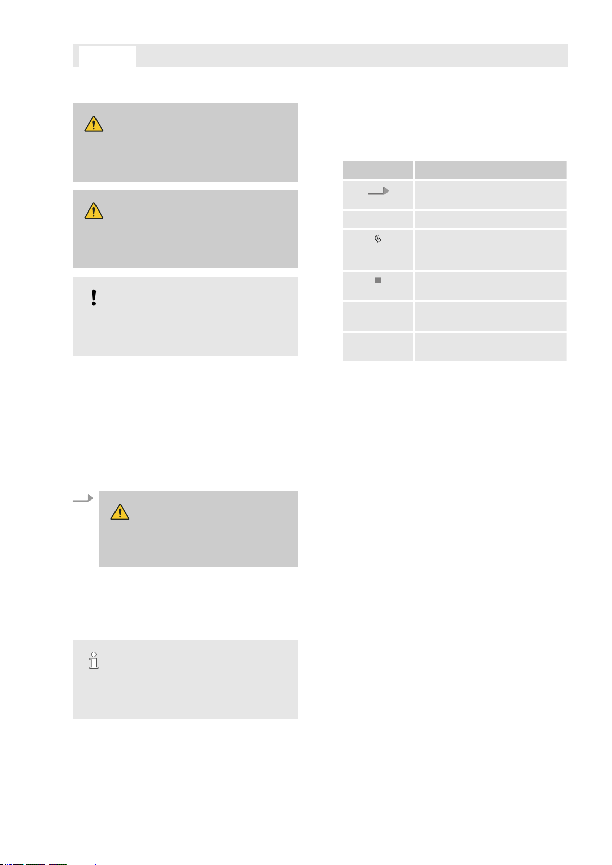
To highlight procedural instructions, results, lists,
references, and other elements, the following
identifiers are used in this manual:
Identifier Explanation
Step-by-step procedural
instructions
ð
[Button] Controls or signals (e.g., dis-
“Display” Screen elements (e.g., buttons,
Results of procedural steps
References to sections of this
manual and to other applicable
documents
Lists without a defined
sequence
play elements or signal lamps)
assignment of function keys)
Safety Instructions in Procedural Instructions
Safety instructions can refer to specific, individual
procedural instructions. Such safety instructions
are embedded in the procedural instructions so
that they do not interrupt the reading flow when
performing the activity. The signal words
described above are used.
Example:
WARNING!
Check temperature before
touching heater jacket. If too hot
let it cool down!
Carefully pull out heater jacket in the direction of the rear panel.
Tips and Recommendations
This symbol highlights useful tips and recommendations, as well as useful information for efficient and fault-free operation.
1.3 Intended Use Statement
Intended Use
The X-STREAM Enhanced Chemiluminescence
Detector (XECLD) is an analyzer intended for
measurement of NO/NO2/NOx concentrations in
exhaust fumes and clean gas mixtures.
The analyzed exhaust fumes may come from all
possible types of power plants with burning processes or from combustion engines.
Furthermore, the XECLD can be used for gas
purity measurements.
In principle, the XECLD is fit for analyzing nonflammable gases and can be set up as a tabletop
unit or as a rackmount device.
The XECLD may only be supplied with power
and gases and be operated in surroundings as
specified in this manual (Ä Chapter 3.1 “Housing
Data, Connection Data, Environmental Conditions and Emissions” on page 43).
The Analyzer is intended for commercial use in
industrial or non-industrial sectors. The intended
use is limited to measuring and testing where
usage in laboratories is included.
Identifiers in this Manual
X-STREAM Enhanced XECLD - Chemiluminescence Detection Gas Analyzer 13
Page 14

Safety Instructions
00809-0100-3975. Rev AB
April 2021
Instruction Manual
Page 14 of 264
Dangerous Misuse
WARNING!
Danger of injury and material damage
due to misuse!
If the device is not used as intended, dangerous situations may occur. Material
assets may be damaged.
– Never use in unventilated locations.
– Only supply Analyzer with gases as
Ä
described in this manual
Chapter
3.1.4 “Gas Supply Data” on page 46.
– Make sure that gas connections are
never unintentionally swapped.
– Always check gas connections and tub-
ings for leakage as described in this
manual Ä Chapter 9.9 “Performing a
Leakage Test” on page 187.
– Only operate the Analyzer within the
boundaries specified in this manual
Ä
Chapter 3 “Technical Data”
on page 42.
– Always check additional operating
boundary restrictions due to individually
ordered configurations.
– The Analyzer may only be operated
indoors in water and dust-protected
environments. Use only in explosionprotected areas.
1.4 Authorized Personnel
Special Training
Authorized personnel who install, operate,
service and maintain the analyzer need to be fully
instructed and trained. Authorized personnel who
install, operate, service and maintain the analyzer
need to be fully instructed and trained by the
qualified personnel of the operating company and
the manufacturer.
Analyzer operator
The Analyzer operator is qualified to perform
basic tasks that do not require the opening of the
Analyzer housing or the use of tools.
The Analyzer operator is trained in safety matters, on-site special features, regulations on-site
and basics of gas measuring in a way that meets
legal and other official requirements to work with
the Analyzer.
Due to personality, experience and education, the
Analyzer operator is capable of working in such a
way as to keep all personnel in the industrial or
laboratory environment safe.
Authorized service personnel
Authorized service personnel are trained and
authorized by Emerson Rosemount to perform
specific service related tasks on the Analyzer.
Authorized service personnel have been extensively trained to understand the Emerson exhaust
measuring product lines and have acquired deep
knowledge about local safety regulations and
technical standards during previous roles or
training. The knowledge and experience gained
enables these authorized service personnel to
identify and avoid potential danger for themselves and others.
Laboratory researchers
Laboratory researchers have a locally recognized
university diploma (Bachelor’s degree equivalent
or higher) qualifying them to analyze automotive
and industrial exhausts. Laboratory researchers
have, in the scope of their activities, already
gained experience in working with technical laboratory equipment (measuring and monitoring
devices). Laboratory researchers are familiar with
locally applicable safety regulations and guidelines for working in a laboratory setting.
Due to their professional experience and their
analytical, methodological and technical knowledge gained through their studies, laboratory
researchers are able to safely perform the following tasks with valid results:
Required Qualifications
TThe following job titles will appear in this manual
allocated to procedures for which they are qualified:
Always make sure that only personnel that meet
the special requirements as described in the following paragraphs are assigned to the described
tasks.
n Erecting safe measurement setups with regard
to the state-of-the-art.
n Designing, evaluating and interpreting a series
of tests.
n Adapting parameters of the measurement
setup in a targeted manner.
X-STREAM Enhanced XECLD - Chemiluminescence Detection Gas Analyzer14
Page 15

Safety Instructions
00809-0100-3975. Rev AB
April 2021
Instruction Manual
Page 15 of 264
The Analyzer-specific knowledge and skills of the
laboratory researcher exceed or at least match
those of an on-site service technician. Therefore
Laboratory researchers may perform all Analyzer-related tasks, an on-site service technician
is required for.
On-site service technician
The on-site service technician is assigned by the
operator to perform service tasks that may
involve opening the Analyzer housing.
On-site service technicians are also capable of
performing comprehensive repair work which
demands manual dexterity and a high level of
mechanical or technical qualification. This qualification enables the on-site service technician to
for example handle fasteners, sheet metal parts,
electrical components and fragile components.
On-site service technicians are trained, have the
expertise, and have familiarity with all applicable
regulations to be able to complete the tasks
entrusted to them. They are also able to independently, detect and avoid any possible hazards
at the Analyzer itself or operation site.
System integrator
Systems integrators are trained specialists, who
are familiar with the interfaces provided by the
Analyzer and its specification. System integrators
are allowed to perform each and every action on
the device in this manual and are able to connect
the device to appropriate external systems for
processing the counting data.
System integrators are familiar with the locally
applicable safety regulations and guidelines for
working in an industrial environment (for example
a power plant or incineration facility) setting.
1.5 Personal Protective Gear
Mandatory Protective Gear on Site
Only Analyzer-specific stipulations can be given
in this manual regarding the protective equipment, since specific regulations on site are not
known.
The required special protective equipment for
working on site must be worn in addition to the
protective equipment described in this manual. If
the protective equipment described in this
manual (for example safety gloves) is the same
as in the operating instructions of other manufacturers, always wear the version which guarantees
the higher standard of safety.
Description of Protective Equipment
The following list describes all protective equipment that must be worn for working with the Analyzer. At the introduction of every step-by-step
instruction, the specific protective equipment that
is to be worn is listed.
Safety gloves
Safety gloves are designed to protect the hands
from friction, abrasions, puncture wounds or
deeper wounds as well as coming into contact
with hot surfaces.
Safety shoes
Safety shoes protect against injuries of the feet
due to falling or pointed objects, as well as
against slipping.
Safety shoes exhibit the following characteristics:
n High skid resistance
n Steel caps as toe protection
n Strong upper material
n Puncture-resistant soles
Safety shoes must satisfy at least the applicable
requirements of protection class 3 according to
ISO 20345 or the requirements of other local regulations such as ASTM F2413-1
1.
1.6 Residual Risks
1.6.1 Unspecified Hazard
Unsuitable spare parts
WARNING!
Danger of injuries when using unsuitable spare parts!
If unsuitable spare parts are used, unforseeable risks may arise. Fire, electrical
shocks, gas poisonings, cuts or other injuries may be the result if unsuitable spare
parts are used.
– Only purchase original spare parts from
the manufacturer.
– Order only and exactly the spare parts
listed on the spare parts list in this
manual or a spare parts list provided by
the manufacturer.
X-STREAM Enhanced XECLD - Chemiluminescence Detection Gas Analyzer 15
Page 16
Safety Instructions
00809-0100-3975. Rev AB
April 2021
Instruction Manual
Page 16 of 264
1.6.2 Electrical Hazard
Electrical Shock
DANGER!
Risk of death due to electric voltage!
The Analyzer works from a mains voltage.
Incorrectly handling the Analyzer or connecting cables can result in a fatal electrical shock.
– Do not operate Analyzer without secure
covers.
– Do not open Analyzer whilst Analyzer is
energized.
– Do not operate with damaged cables.
Replace damaged cables immediately.
– Do not perform any tasks on mains-
voltage-components. Use licensed electricians only!
– Never operate without a protective
earth.
– Do not replace cables or other electrical
components of the Analyzer on your
own. Contact manufacturer.
– Never connect the power supply to any
voltage other than that specified within
Ä
the technical data
“Power Connection Data” on page 45.
High Voltage Components
WARNING!
Risk of electrical shock on high voltage
components!
The Ozonator works with high voltages.
Touching the energized ozonator may
result in an electric shock.
– Do not operate Ozonator without secure
covers.
– Only allow authorized service personnel
to perform tasks on the ozonator.
– Never open any cover while the Ana-
lyzer is connected to a power supply.
Chapter 3.1.3
Wrong Supply Voltage
NOTICE!
Risk of damaged Analyzer when using
wrong supply voltage!
If the Analyzer is supplied with a voltage
other than specified in this manual
(Ä Chapter 3.1.3 “Power Connection Data”
on page 45) it may be damaged irreparably.
– Only connect supply voltages as speci-
fied in technical data.
1.6.3 Chemical Hazard
Harmful Gases
WARNING!
Risk of poisoning by inhalation of
ozone or exhaust fumes!
The Analyzer is supplied with exhaust
fumes and generates Ozone. Ozone is
harmful to health and should not be
inhaled in concentrations above the officially specified limits. Exhaust fumes may
be poisonous.
– Only use the Analyzer in locations that
have adequate ventilation that meet the
local legal requirements.
– Test the gas tightness as described in
this manual.
– Do not operate the Analyzer with a
defective housing fans. Replace defective fan immediately.
– Treat exhaust gases only according to
local regulations.
– Purge analyzer with nitrogen (N2) before
opening housing and gas connections.
– Only open unpressurized Analyzers.
X-STREAM Enhanced XECLD - Chemiluminescence Detection Gas Analyzer16
Page 17

Safety Instructions
00809-0100-3975. Rev AB
April 2021
Instruction Manual
Page 17 of 264
1.6.4 Fire and Burns Hazards
Electrical Fire
WARNING!
Fire hazard due to use of unsuitable
fuses!
If unsuitable fuses are used or fuses are
bridged, electrical fires may occur.
– Only use fuses as described in this
manual.
– Never bridge fuses. Never operate
without fuses.
Flammable Gases
WARNING!
Risk of fire and explosion injuries!
If the Analyzer is supplied with flammable
gases fire and explosions may occur.
– Never supply the Analyzer with flam-
mable gases.
– Always purge gas paths as described in
this manual.
Heated Components
WARNING!
Risk of burns due to temperatures
exceeding specification!
Certain components can reach very high
temperatures on their surfaces. Contact
with these surfaces may cause burns:
Converter (Inner parts): 500 °C (930 °F)
Converter (Housing): 80 °C (176 °F)
Gas-Connectors: 75 °C (170 °F)
Module cover (top side): 90 °C (195 °F)
– Never operate with housing open.
– Never operate with a defective housing
fan.
– Always switch off first and allow to cool
for 60 minutes. Only when the Analyzer
has cooled down:
– Touch top cover.
– Open housing.
– Carry out work on the gas connec-
tions
– Follow the instructions in this manual
exactly for activities inside the housing.
– Observe signage indications of hot sur-
faces.
1.6.5 Mechanical Hazards
Falling Objects
WARNING!
Risk of injuries caused by falling
objects!
If the Analyzer or any components fall (for
example caused by mishandling), injuries
may result.
– Always wear additional protective gear
as described in this manual.
– Handle Analyzer and components with
care.
X-STREAM Enhanced XECLD - Chemiluminescence Detection Gas Analyzer 17
Page 18

Safety Instructions
00809-0100-3975. Rev AB
April 2021
Instruction Manual
Page 18 of 264
Sharp Edges and Corners
CAUTION!
Risk of injuries at edges and corners!
The rack mounting brackets protrude and
bumping them may cause injuries; especially in transit. During activities inside the
housing, contact with sharp-edged components is possible.
– When in transit, remove the mounting
brackets.
– Only carry out activities within the
housing in accordance with the instructions in this manual.
Finger Injuries Caused by Fan
CAUTION!
Risk of injury to fingers on the housing
fan!
If the finger protection is not reinstalled
after working on the housing fan, crushing
and impact injuries may result if fan is
reached into.
– Always install finger protection as
described.
– Never reach into the fan.
1.7 On the use of figures
Product variants
The Analyzer is available in different variants and
configurations. In this manual, a distinct configuration is shown which illustrates all tasks or information provided. In some sections however, the
Analyzer configuration may differ. This will be
more common in gas connector illustrations (for
example, the existence of a purge connector or
the connector type), the usage of optional I/Ocards and screw terminals, and in the distinction
between rack mounting or the use of stand feet.
Please contact customer service if unsure some
information does not apply to your configuration.
X-STREAM Enhanced XECLD - Chemiluminescence Detection Gas Analyzer18
Page 19

2 Technical Description
00809-0100-3975. Rev AB
April 2021
Instruction Manual
Page 19 of 264
Technical Description
2.1 Tools and Consumable Materials
Tools
To work with the Analyzer, use a set of standard
tools (for example, screwdrivers (cross-head and
flat-head) and wrenches.
Additionally the following special tools are
needed:
External hexagon nut with extension (5.5 mm)
The external hexagon nut with extension enables
to unscrew hexagon socket nuts in an distance of
approx. 20 cm (8 in).
The width across flat-head screwdrivers must be
approx. 5.5 mm (0.22 in).
Consumable Materials
The following consumable materials are needed.
Do not use other materials than these described:
Materials:
Converter test gas supply
n
Detergents
n
Leakage test gas supply (N2 or He)
n
Replacement fuse
n
Replacement housing filter
n
Span gas supply
n
USB storage device
n
Zero gas supply (N2)
n
Air-supply gas
n
Air-supply gas
Air-supply gas is pressurized or synthetic air and
meets the technical requirements Ä Chapter
3.1.4 “Gas Supply Data” on page 46.
Do not use pure oxygen as air-supply gas.
Converter test gas supply
Converter test gas has a known concentration of
NO2 (< 500 ppm) and meets the technical
requirements.
A supply of converter test gas can be connected
to the sample-in-line independently from sample
gas or air supply.
Detergents
The detergent is not chemically aggressive, is
free of solvents and does not contain any hydrocarbons.
Leakage test gas supply (N2 or He)
A supply of test gas (N2 or He) which can be connected to the exhaust line independently from
sample gas or air supply (e. g. gas bottle).
The leakage test gas supply must be able to at
least build up pressure of 1,034 hPa (15 psig)
and must provide an option to shut down so that
connected gas lines remain under pressure.
Replacement fuse
The replacement fuse matches the description
and the technical data stated in the spare parts
Ä
list in this manual
Replacement housing filter
The replacement housing filter is available at
Emerson Rosemount.
The filter fits into the seat at the air inlet at the
rear of the housing and meets the requirements
e. g. considering filtered particulate size.
Use replacement filters as listed on the spare
parts list only.
Span gas supply
Span gas has a known concentration of NO and
meets the technical requirements Ä Chapter
3.1.4 “Gas Supply Data” on page 46.
A supply of span gas can be connected to the
sample-in-line independently from sample gas.
Span gas should have a concentration of 80 % to
110 % of the upper measuring range limit to the
gas path. Using lower concentrations may
decrease accuracy when measuring above the
span gas concentration!
USB storage device
The USB-Storage Device is used for external
data backups and must meet the specifications of
USB 1.0 or higher. The device plug must be a
USB male connector (type A).
It is recommended to use storage devices manufactured by renowned brands such as SANDISK,
KINGSTON, TOSHIBA etc..
Always test functionality of USB-Storage Device
before using it for (important) backups.
“Fuses” on page 227.
X-STREAM Enhanced XECLD - Chemiluminescence Detection Gas Analyzer 19
Page 20

Technical Description
00809-0100-3975. Rev AB
April 2021
Instruction Manual
Page 20 of 264
Zero gas supply (N2)
The zero gas supply is N2 of high purity.
The nitrogen should, as a minimum, be of quality
of 5.0, which means nitrogen of purity ≥
99.999 %. If such gas is not available, the substitute must be dry, clean and free of corrosives or
components containing solvents. It has to be free
of components to be measured, to minimize
cross interferences.
The supply of zero gas (N2) can be connected to
the sample gas connector independently from
sample gas or air supply.
The zero gas supply must also meet the technical
Ä
requirements
on page 46.
Chapter 3.1.4 “Gas Supply Data”
2.2 Inputs and Outputs
2.2.1 Inputs and Outputs: General Information
Limits and SELV
All external inputs shall provide reinforced or
double insulation for protection against electric
shock and with output voltages below the limits of
6.3.1 of 61010-1 or 30 V RMS and 42.4 V peak
or 60 V DC.
Connect only secondary circuits that are
designed in a way that under normal and single
fault conditions, the voltage between any two
parts of the SELV circuit does not exceed safe
values.
2.2.2 Inputs and Outputs: Data Connectors
X-STREAM Enhanced XECLD - Chemiluminescence Detection Gas Analyzer20
Page 21

2.2.2.1 Overview of Backpanel Configurations
00809-0100-3975. Rev AB
April 2021
Instruction Manual
Page 21 of 264
Available Configurations
The Following configurations are available for the Analyzer:
Technical Description
Option
no.
1 - -
Optional I/Os Screw Terminal Exten-
sion
Description
Ä
“Data Connectors - Without Optional
I/Os - Without Screw Terminal Extensions”
on page 21
2 Digital I/Os -
Ä
“Data Connectors - With Optional Digital
I/Os - Without Screw Terminal Extensions”
on page 22
3 Analog Input -
Ä
“Data Connectors - With Optional Analog
Inputs - Without Screw Terminal Extensions” on page 22
4 Digital I/Os yes
Ä
“Data Connectors - With Optional Digital
I/Os - With Screw Terminal Extensions”
on page 23
5 Analog Input yes
Ä
“Data Connectors - With Analog Input With Screw Terminal Extensions”
on page 23
Data Connectors - Without Optional I/Os - Without Screw Terminal Extensions
Fig. 6: Option 1
1 USB-port 1 (USB-A)
2 USB-port 2 (mini-USB)
3 RJ45 Ethernet connector (2)
4 RJ45 Ethernet connector (1, process port)
5 CAN interface (reserved for future use)
7 Service port
8 Analog outputs / relay outputs
9 Serial interface (RS 232 / Modbus 485)
X-STREAM Enhanced XECLD - Chemiluminescence Detection Gas Analyzer 21
Page 22

Technical Description
00809-0100-3975. Rev AB
April 2021
Instruction Manual
Page 22 of 264
Data Connectors - With Optional Digital I/Os - Without Screw Terminal Extensions
Fig. 7: Option 2
1 USB-port 1 (USB-A)
2 USB-port 2 (mini-USB)
3 RJ45 Ethernet connector (2)
4 RJ45 Ethernet connector (1, process port)
5 CAN interface (reserved for future use)
6 Digital in- / outputs
7 Service port
8 Analog outputs / relay outputs
9 Serial interface (RS 232 / Modbus 485)
Data Connectors - With Optional Analog Inputs - Without Screw Terminal Extensions
Fig. 8: Option 3
1 USB-port 1 (USB-A)
2 USB-port 2 (mini-USB)
3 RJ45 Ethernet connector (2)
4 RJ45 Ethernet connector (1, process port)
6 9-pin Analog input
7 Service port
8 Analog outputs / relay outputs
9 Serial interface (RS 232 / Modbus 485)
5 CAN interface (reserved for future use)
X-STREAM Enhanced XECLD - Chemiluminescence Detection Gas Analyzer22
Page 23

Technical Description
00809-0100-3975. Rev AB
April 2021
Instruction Manual
Page 23 of 264
Data Connectors - With Optional Digital I/Os - With Screw Terminal Extensions
Fig. 9: Option 4
1 USB-port 1 (USB-A)
2 USB-port 2 (mini-USB)
3 RJ45 Ethernet connector (2)
4 RJ45 Ethernet connector (1, process port)
5 CAN interface (reserved for future use)
6 Screw terminal extension XSTD
7 Screw terminal extension XSTA
8 Ribbon cable connector (XPSA)
9 Ribbon cable connector (XSTA)
Data Connectors - With Analog Input - With Screw Terminal Extensions
Fig. 10: Option 5
1 USB-port 1 (USB-A)
2 USB-port 2 (mini-USB)
3 RJ45 Ethernet connector (2)
4 RJ45 Ethernet connector (1, process port)
5 CAN interface (reserved for future use)
6 Ribbon cable connector (XSTI)
7 Screw terminal extension XSTI)
8 Screw terminal extension (XSTA)
9 Ribbon cable connector (XPSA)
10 Ribbon cable connector (XSTA)
2.2.2.2 Description of Data Connectors
USB connectors
(Fig. 6/1 + 2)
X-STREAM Enhanced XECLD - Chemiluminescence Detection Gas Analyzer 23
Page 24
Technical Description
00809-0100-3975. Rev AB
April 2021
Instruction Manual
Page 24 of 264
Fig. 11: USB-ports
The device is equipped with two USB-connectors. Only one connector can be used at any one
time. The active USB-connector is selected via
software settings.
External data storage devices can be connected
to the USB-A connector (Fig. 11/1). The miniUSB port (Fig. 11/3) is designed to connect
measurement devices (computers).
Ethernet1 can be used to connect the analyzer to
a network.
Ethernet2 can be used to connect a PC directly
via crossover cable.
Fig. 12: RJ45 connector
# Signal
1 TX +
2 TX -
Overview of LED-states: Ä “Status LED”
on page 38
RJ45 Ethernet Connectors
(Fig. 6/3 + 4)
The Ethernet (Modbus) interface offers the same
form of communication with a data acquisition
system as a serial interface. Furthermore, this
interface enables to connect the analyzer to a
network, providing webbrowser access. This
interface is electrically isolated from the unit’s
electronic components and enables the construction of a network of several analyzers.
3 RX +
4 not used
5 not used
6 RX -
7 not used
8 not used
X-STREAM Enhanced XECLD - Chemiluminescence Detection Gas Analyzer24
Page 25

Technical Description
00809-0100-3975. Rev AB
April 2021
Instruction Manual
Page 25 of 264
Option: Analog inputs
(Fig. 8/6)
Instead of having analog inputs the analyzer is optionally available with digital in/outputs.
Optionally, the Analyzer can be equipped with a 9-pin analog input. The pinout is as follows:
Fig. 13: Passive Analog Interface (X5-connector,
option 2)
# Signals Note
A1 BR1 fit a wire bridge here to apply analog signal
A2 BR1
A3 not used -
A4 BR2 fit a wire bridge here to apply analog signal
A5 BR2
in current mode to input 2**
A6 Input 1 high (+) -
A7 Input 1 low (-) -
A8 Input 2 low (-) -
A9 Input 2 high (+) -
*alternatively set jumper P2 on electronics board XASI.
**alternatively set jumper P1 on electronics board XASI.
Electrical specifications of two analog inputs:
n 0–1 (10) V, software selectable; Rin = 100 kΩ
n Optional (requires to fit wire bridges, see figures): 0–20 mA ; Rin = 50 Ω
n Protected against overload up to ± 15 V or ± 20 mA
in current mode to input 1*
X-STREAM Enhanced XECLD - Chemiluminescence Detection Gas Analyzer 25
Page 26

Technical Description
00809-0100-3975. Rev AB
April 2021
Instruction Manual
Page 26 of 264
Fig. 14: Passive Analog Input
1 Passive Analyzer input
2 Input signal, high
3 Wire bridge (optional)
4 Input signal, low
The optional wire bridge is used for current mode selection.
If the Analyzer is equipped with analog inputs, a terminal extension is available Ä “XSTI adapter”
on page 34.
Option: Digital In/Outputs
(Fig. 7/6)
Instead of having digital in/outputs the analyzer is optionally available with an analog inputs.
Optionally, the Analyzer can be equipped with a 37-pin digital in/output interface. The pinout is as follows:
X-STREAM Enhanced XECLD - Chemiluminescence Detection Gas Analyzer26
Page 27

Technical Description
00809-0100-3975. Rev AB
April 2021
Instruction Manual
Page 27 of 264
Fig. 15: Digital in- / outputs (optional)
If the Analyzer is equipped with a digital in/output, a terminal extension is available Ä “XSTD adapter”
on page 34.
Service Port
(Fig. 6/7)
The Service port connector is configured as an
RS 232 connector with pinout as shown here:
Fig. 16: Service port
X-STREAM Enhanced XECLD - Chemiluminescence Detection Gas Analyzer 27
Page 28

Technical Description
00809-0100-3975. Rev AB
April 2021
Instruction Manual
Page 28 of 264
# Signals
1 Common
2 RSD
3 TXD
4 not used
5 Common
# Signals
6 not used
7 not used
8 not used
9 not used
X-STREAM Enhanced XECLD - Chemiluminescence Detection Gas Analyzer28
Page 29

Analog Outputs / Relay Output (X1)
00809-0100-3975. Rev AB
April 2021
Instruction Manual
Page 29 of 264
(Fig. 6/8)
Technical Description
Fig. 17: Analog Outputs / Relay outputs
The X1-Interface is by default configured as shown in Fig. 17.
Five software-configurable analog outputs can be used to supply external devices with analog signals.
The 4 relay-outputs are by default assigned according to NAMUR-specification NE 107 (status signals).
The technical data of analog outputs and relay outputs is as follows:
Data Value Unit
Current, analog output 4 (0)–20 mA
Burden (RB), analog output < 500
Ω
Current, relay output 1 A
Voltage, relay output 30 VDC
Load, relay output 30 W
By default, the Analyzer is fitted with one output, which can transmit data on concentration levels to an
external data acquisition system. Up to five analog outputs can be installed.
The analog outputs support several operation modes, such as 4-20 mA, 0-20 mA, as well as the NAMUR NE
43 specifications (incl. Live Zero). Operation modes can be set in a software menu (6-76).
The factory setting for analog outputs is 4-20 mA.
X-STREAM analyzers support up to five analog outputs that do not always have to be assigned to measurement channels which are physically present.
If a unit features less than five channels, the remaining analog outputs can be used to transmit concentration
levels with a different resolution. For example, the XECLD could be set up as follows:
Output 1: 0 … 10 ppm NO = 4 … 20 mA
Output 2: 0 … 100 ppm NO = 4 … 20 mA
X-STREAM Enhanced XECLD - Chemiluminescence Detection Gas Analyzer 29
Page 30

Technical Description
00809-0100-3975. Rev AB
April 2021
Instruction Manual
Page 30 of 264
Serial Interface (X2)
(Fig. 6/9)
A serial interface with the Modbus protocol allows communication with external data acquisition systems.
The interface enables the exchange and modification of measurement and analyzer signals, analyzer status
monitoring as well as remote activation of procedures.
The serial Interface (X2) may have different signal configurations:
Fig. 18: Serial interface
Signals
# MOD 485/2 wire MOD 485/4 wire RS232
1 Common Common Common
2 not used not used RSD
3 not used not used TXD
4 not used RXD1 (+) not used
5 D1 (+) TXD1 (+) Common
6 not used not used not used
7 not used not used not used
8 not used RXD1 (-) not used
9 D0 (-) TXD1 (-) not used
The active configuration is indicated by a marking on a table below the Serial interface:
X-STREAM Enhanced XECLD - Chemiluminescence Detection Gas Analyzer30
Page 31

Technical Description
00809-0100-3975. Rev AB
April 2021
Instruction Manual
Page 31 of 264
Fig. 19: Configuration table
In the example shown, the X2 connector is configured as an RS 232 interface (Fig. 19).
2.2.2.3 Screw Terminal Extensions (Optional)
Terminal Extensions
Fig. 20: Screw terminal extensions
Screw terminals are available optionally and allow the user to establish individual configurations.
Screw terminal extensions are available for the optional 37-pin connector (Fig. 20/1, alternatively for a 9-pin
analog input and for the 25-pin analog / relay output (Fig. 20/3). Via flat cable the serial interface X2
(Fig. 20/2) can also be connected to the lower part of the right screw terminal extension (Fig. 20/4).
X-STREAM Enhanced XECLD - Chemiluminescence Detection Gas Analyzer 31
Page 32

Technical Description
00809-0100-3975. Rev AB
April 2021
Instruction Manual
Page 32 of 264
Equipotential Bonding
Fig. 21: Cable leads
The shield of cables connected to terminal extensions must be routed through the shield connection
(Fig. 21/2) to establish equipotential bonding. Screw terminals (Fig. 21/1) are described in the following sections.
Connection Data
All screw terminal extensions share the following
technical properties:
Property Value
Stripping length 0.2" (5 mm)
Thread M2
Property Value
Wire gauge, recommended
AWG 26 – AWG 16
(0.14 – 1.5 mm²)
Tightening torque, min 2.21 in lb (0.25 Nm)
X-STREAM Enhanced XECLD - Chemiluminescence Detection Gas Analyzer32
Page 33

XSTA adapter
00809-0100-3975. Rev AB
April 2021
Instruction Manual
Page 33 of 264
Technical Description
Fig. 22: XSTA adapter (Terminal extension)
The Terminal extension for the XSTA adapter allows to individually wire analog outputs and relay outputs (X1
connector). It also offers a possiblilty to connect the X2 connector via flat cable.
The Analog Outputs (Fig. 22/P2.1 – 2.10) can be indiviually configured via software settings.
The configuration of Relay Outputs (Fig. 22/P3.3 – P4.2) is set per factory setting and represents standard
NAMUR status signals. The signals set may also be adapted via software settings.
The Serial Interface (Fig. 22/P4.4 – P4.12) may be set to different modes of operation. For a description of
the possible configurations see Ä Serial Interface (X2) on page 28.
In default configuration, the connectors 2.11 – P3.2 and P4.3 are not used.
When wiring individually, make sure the cable shielding is properly connected to the equipotential
bonding Ä “Equipotential Bonding” on page 32.
X-STREAM Enhanced XECLD - Chemiluminescence Detection Gas Analyzer 33
Page 34

Technical Description
00809-0100-3975. Rev AB
April 2021
Instruction Manual
Page 34 of 264
XSTD adapter
An XSTD adapter can optionally be used to connect digital I/O cables to screw-type terminals instead of
Submin-D plugs and sockets; it is plugged into the digital I/O Submin-D connectors on the unit.
Fig. 23: XSTD adapter (Terminal extension)
XSTI adapter
An XSTI adapter can optionally be used to connect analog input cables to screw-type terminals instead of
Submin-D plugs and sockets; it is plugged into the optional analog input connector on the unit.
X-STREAM Enhanced XECLD - Chemiluminescence Detection Gas Analyzer34
Page 35

Technical Description
00809-0100-3975. Rev AB
April 2021
Instruction Manual
Page 35 of 264
Fig. 24: XSTI adapter (Terminal extension)
2.2.3 Inputs and Outputs: Gas Connectors
Fig. 25: Gas connections
1 EXHAUST
2 SAMPLE IN
3 AIR IN
4 PURGE (optional)
X-STREAM Enhanced XECLD - Chemiluminescence Detection Gas Analyzer 35
Page 36

Technical Description
00809-0100-3975. Rev AB
April 2021
Instruction Manual
Page 36 of 264
Three gas connectors and an optional fourth are located on the back panel of the Analyzer (Fig. 25/1 – 4).
The PURGE gas connector is only available for direct connection of PTFE (e. g. Teflon®) or FKM (e. g. Viton
®
) tubings. EXHAUST, SAMPLE IN and AIR IN connectors can be ordered in two different versions:
n 6 or 10 mm fitting
n 1/4" or 3/8" fitting
Sample gas must be supplied at the SAMPLE IN connector (Fig. 25/2). Pressurized Air as specified within
this manual (Ä Chapter 2.2.3 “Inputs and Outputs: Gas Connectors” on page 35) that can be used to supply
the Ozonator is connected to the AIR IN connector (Fig. 25/3). The exhaust's gas line must be connected to
the EXHAUST connector (Fig. 25/1). Optionally, a PURGE connector (Fig. 25/4) which may be used as a
purge gas inlet can be installed.
Technical specifications on connected gases and systems: Ä Chapter 3.1.4 “Gas Supply Data”
on page 46
2.2.4 Electrical connectors
Power Connector
Fig. 26: Power connector
The Power connector (Fig. 26/1) is located at the
lower left of the backpanel.
Only connect the supplied IEC C13 connector
cable!
Equipotential Bonding Connector
Fig. 27: Equipotential Bonding Connector
The equipotential bonding connector (Fig. 27/1)
is located at the lower left of the backpanel,
directly below the power connector. Use the equipotential bonding connector for grounding the
Analyzer.
2.3 Controls, Signals and Display
ON/OFF switch
Fig. 28: ON/OFF switch
The ON/OFF switch (Fig. 28/1) is located on the
left side of the rear panel, adjacent to the IEC
connector.
X-STREAM Enhanced XECLD - Chemiluminescence Detection Gas Analyzer36
Page 37

The ON/OFF switch connects or disconnects the
00809-0100-3975. Rev AB
April 2021
Instruction Manual
Page 37 of 264
power supply to the Analyzer.
Technical Description
X-STREAM Enhanced XECLD - Chemiluminescence Detection Gas Analyzer 37
Page 38

Technical Description
00809-0100-3975. Rev AB
April 2021
Instruction Manual
Page 38 of 264
Status LED
Fig. 29: Status LEDs
1 LED 1
2 LED 2
The Status LEDs are located on the left side of the backpanel, next to the air inlet of case ventilation and
above the RJ45 connectors. The Status LEDs indicate the Analyzer's status considering software and operational readiness. LED 1 (Fig. 29/1) is labeled "L1" and LED 2 (Fig. 29/2) "L2".
LED state Meaning Recommended action
LED 1: Blinking (green)
Regular state of operation.
LED 2: constantly ON (green)
LED 1: Blinking (red) NAMUR "Failure" state. Check displayed failure descrip-
tion and consult troubleshooting in
the appendix
Ä
Appendix “Trou-
bleshooting” on page 241.
LED 1: constantly ON (green)
LED 2: constantly ON (green)
Analyzer not properly programmed.
Inform customer services.
Let authorized service personnel
program analyzer.
LED 1 and LED 2 : blinking alternately (green)
New program version has just
been loaded. User input is
expected.
Mind displayed messages or let
authorized service personell login
via TELNET.
X-STREAM Enhanced XECLD - Chemiluminescence Detection Gas Analyzer38
Page 39

Technical Description
00809-0100-3975. Rev AB
April 2021
Instruction Manual
Page 39 of 264
POWER LED
Fig. 30: Power LED
1 POWER LED
The POWER LED (Fig. 30/1) is located in the
upper part of the back panel above the X1-Interface. When the Analyzer is connected to the
power grid and the ON/OFF switch is switched to
postition [I] the POWER LED is lit.
Softkeys
WARNING!
Only open housing, when POWER LED
is not lit!
Fig. 31: Softkeys
The softkeys are located in the center of the front
panel. The main function of the soft keys is navigating through the software menu.
Via softkeys the software menu can be accessed,
tasks can be executed and status messages can
be displayed.
Softkey Function (s)
UP Key
n Navigate
up within a
menu
DOWN Key
n Navigate
down within
a menu
RIGHT Key
n Enter the
highlighted
sub menu
X-STREAM Enhanced XECLD - Chemiluminescence Detection Gas Analyzer 39
Page 40

Technical Description
00809-0100-3975. Rev AB
April 2021
Instruction Manual
Page 40 of 264
Softkey Function (s)
LEFT Key
n Return from
a sub-menu
to the
higher level
menu.
Softkey Function (s)
HOME Key
n Return to
home
screen
ENTER Key
n Execute a
function
n Enter a
value
X-STREAM Enhanced XECLD - Chemiluminescence Detection Gas Analyzer40
Page 41

Display
00809-0100-3975. Rev AB
April 2021
Instruction Manual
Page 41 of 264
Technical Description
Fig. 32: Display
The display is located at the center of the front panel (Fig. 32).
The contents displayed are divided in four sections:
In the status symbol section (Fig. 32/1) a selection of symbols describes the states of operation. The menu
title line (Fig. 32/2) indicates the current active menu and – if applicable – the number of the sub-menu
pages. In the Menu sections, menu entries (Fig. 32/3) and their associated values or settings are shown. On
the bottom of the display, the status message line (Fig. 32/4) displays date and time or any pending error
messages.
Refer to Ä Chapter 5.3 “Software” on page 59 for a detailed description.
X-STREAM Enhanced XECLD - Chemiluminescence Detection Gas Analyzer 41
Page 42

Technical Data
00809-0100-3975. Rev AB
April 2021
Instruction Manual
Page 42 of 264
3 Technical Data
Units Rounded
The values in imperal units given in the following are calculated from metric units.
The calculated values are rounded. This
can produce small deviations from the
actual values.
X-STREAM Enhanced XECLD - Chemiluminescence Detection Gas Analyzer42
Page 43

Technical Data
00809-0100-3975. Rev AB
April 2021
Instruction Manual
Page 43 of 264
3.1 Housing Data, Connection Data, Environmental Conditions and Emissions
3.1.1 Housing Data
Dimensions (without screw extensions)
Fig. 33: Dimensions
Data Value Unit
Dimension* (length) 369.6 (14.55) mm (in)
Dimension* (width) 440 (17.32) mm (in)
Dimension* (height) 132 (5.2) mm (in)
Weight 12.3 (27.12) kg (lb)
Mounting, Type A 19" rack mount -
Mounting, Type B Table top -
Ingress protection rating IP20 -
Safety clearance** 1 RU
Air flow, housing fan 0.88 (1.15) m³/min (yd³/min)
*Dimensions without housing feet or rack mounting brackets.
**Make sure there is at least one unoccupied Rack Unit (RU) above and underneath the designated
mounting location.
X-STREAM Enhanced XECLD - Chemiluminescence Detection Gas Analyzer 43
Page 44

Technical Data
00809-0100-3975. Rev AB
April 2021
Instruction Manual
Page 44 of 264
Dimensions (with screw extensions)
Fig. 34: Dimensions
Data Value Unit
Dimension* (length) 411,7 (16.21) mm (in)
Dimension* (width) 440 (17.32) mm (in)
Dimension* (height) 132 (5.2) mm (in)
Weight 12.3 (27.12) kg (lb)
Mounting, Type A 19" rack mount -
Mounting, Type B Table top -
Ingress protection rating IP20 -
Safety clearance** 1 RU
Air flow, housing fan 0.88 (1.15) m³/min (yd³/min)
*Dimensions without housing feet or rack mounting brackets attached.
**Make sure there is at least one unoccupied Rack Unit (RU) above and underneath the designated
mounting location.
X-STREAM Enhanced XECLD - Chemiluminescence Detection Gas Analyzer44
Page 45

3.1.2 Performance Specifications
00809-0100-3975. Rev AB
April 2021
Instruction Manual
Page 45 of 264
Technical Data
Detection limit (4σ)
Linearity
Repeatability
1, 2
1, 2
Response time (t90)
Zero-point drift
1, 2
Span (sensivity) drift
1, 2
3
≤ 2 s for range > 25 ppm
1, 2
≤ 1.0 %
≤ 1.0 %
≤ 0.5 %
4
≤ 4 s for range ≤ 25 ppm
≤ 0.5 % per 24 h
≤ 1.0 % per 24 h
Permissible ambient temperature +5 – +40 °C (+41 – +104 °F)
Zero-point temperature effect
Span (sensitivity) temp. effect
1, 6
1, 6
≤ 2.0 % per 10 K
≤ 3.0 % per 10 K
Maximum gas pressure ≤ 1500 hPa gauge (≤ 21 psig)
Warm-up time
1
Related to full scale.
2
Constant pressure and temperature.
3
From gas analyzer inlet.
4
Electronic damping = 0s.
5
Electronic damping = 3s.
6
Temperature variation: ≤ 10K per hour.
7
Depending on ambient temperature.
7
30 – 60 minutes
5
3.1.3 Power Connection Data
Data Value Unit
Mains overvoltage category, transient II -
Mains connection IEC Connector (C13) -
Mains voltage 100...240 V AC
Net frequency 50 / 60 Hz
Mains cartridge fuse* 5 x 20 (0.2 x 0.79) mm (in)
Power consumption approx. 120 W
Nominal input current, max. 2...1 A
Mains supply voltage fluctuations ± 10 %
Mains Fuse, trip current 4 A
Mains Fuse, nominal voltage 250 V
Mains Fuse, breaking capacity 1500 A @ 250 V AC -
Ä
*Fuses are available from Emerson. Only use fuses listed in the spare parts list
“Fuses” on page 227.
X-STREAM Enhanced XECLD - Chemiluminescence Detection Gas Analyzer 45
Page 46

Technical Data
00809-0100-3975. Rev AB
April 2021
Instruction Manual
Page 46 of 264
3.1.4 Gas Supply Data
Chemical components
NOTICE!
Never apply highly corrosive gases (e. g.
Chlorine or H2S) in concentrations of
approximately 1 % or higher!
X-STREAM Enhanced XECLD - Chemiluminescence Detection Gas Analyzer46
Page 47

Technical Data
00809-0100-3975. Rev AB
April 2021
Instruction Manual
Page 47 of 264
Technical Data
Ä
Only use conditioned gases
Data Value Unit
Sample gas connection, type A 6 mm
Sample gas connection, type B 1/4 in
Air supply connection (ozonator), type A 6 mm
Air supply connection (ozonator), type B 1/4 in
Exhaust outlet, type A 10 mm
Exhaust outlet, type B 3/8 in
Sample gas, pressure 0.6 – 1.5 (8.7 – 21.8) barg (psig)
Chapter 7.6 “Gas Conditioning” on page 165.
Sample gas, flow 500 – 1000 (1831 –
ml/min (in³/h)
3661)
Sample gas, dew point* 0 (23)* °C (°F)
Sample gas, max. temperature 45 (113) °C (°F)
Sample gas, max. particulate size < 2 μm (micron)
Air supply (ozonator), pressure 0.6 – 1.5 (8.7 – 21.8) barg (psig)
Air supply (ozonator), flow 400 – 1000 (1464–
ml/min (in³/h)
3661)
Air supply (ozonator), dew point < -5 (23)* °C (°F)
Air supply (ozonator), max. temperature 45 (113) °C (°F)
Air supply (ozonator), particulate size < 2 μm (micron)
Ozone emission, max.** 3300 ppm
Exhaust emission*** approx. 2000 (7323) ml/min (in³/h)
*Dew points of sample gas must be at least 5 °C (9 °F) below ambient temperature.
**At 300 (1098) ml/min (in³/h) (max. measured laboratory value).
***Contains ozone (O3), NOx and other gases depending on the composition of the sample gas. Exhaust
must be able to freely flow and must not build up back pressure.
Type A or type B connectors are alternatives. Either the Analyzer is fully equipped with type A connectors or it is fully equipped with type B connectors. Mixed configurations with both type A and type Bconnectors are not available.
All pressures stated must be reached directly at the gas connectors. The flow through the analyzer
follows the input pressure.
X-STREAM Enhanced XECLD - Chemiluminescence Detection Gas Analyzer 47
Page 48

Technical Data
00809-0100-3975. Rev AB
April 2021
Instruction Manual
Page 48 of 264
3.1.5 Interface Data
Analog Output / Relay Output (X1)
Data Value Unit
Current, analog output 4 (0) – 20 mA
Burden (RB), analog output < 500
Ω
Current, relay output 1 A
Voltage, relay output 30 V DC
Load, relay output 30 W
Connect only secondary SELV circuits that under normal and single fault conditions, do not exceed
safe values between any two connected components.
Digital Output
Data Value Unit
Voltage, max 30 V
Current, max 1 A
Power, max 30 W
Analog Input
Data Value Unit
Burden (Rin) 100 kΩ
Burden (Rin), wire bridged** 50
Ω
Voltage, range 1* 0 – 1 V DC
Voltage, range 2* 0 – 10 V DC
Input current, wire-bridged** 0 – 20 mA
Overload protection, voltage ±15 V DC
Overload protection, current ±20 mA
*Ranges can be selected in the software menu.
**Optional, if wire bridge is fitted.
X-STREAM Enhanced XECLD - Chemiluminescence Detection Gas Analyzer48
Page 49

Technical Data
00809-0100-3975. Rev AB
April 2021
Instruction Manual
Page 49 of 264
Connect only secondary SELV circuits that under normal and single fault conditions, do not exceed
safe values between any two connected components.
3.1.6 Enviromental Conditions
Data Value Unit
Humidity, at 20°C (68°F) < 90 % (RH)
Humidity, at 40°C (104°F) < 70 % (RH)
Employment height, max* 2000 (6561) m (ft)
Ambient temperature 5 – 45 (41 – 113) °C (°F)
Pollution level, max 2 -
*Above mean sea level.
The Analyzer may only be operated indoors in water and dust-protected environments. Use only in
explosion-protected areas.
3.1.7 Emissions
Dangerous Gas Concentrations
WARNING!
Health problems due to possible
harmful concentrations of gases in
unventilated housings or control cabinets!
If leakages occur and there is no ventilation, dangerous gas concentrations may
occur after short periods of time.
X-STREAM Enhanced XECLD - Chemiluminescence Detection Gas Analyzer 49
Page 50

Technical Data
00809-0100-3975. Rev AB
April 2021
Instruction Manual
Page 50 of 264
Leakage Rate
WARNING!
If leakage is not tested, the stated leakage values are not accurate an may be much higher.
Ä
– Always perform leakage test as specified in this manual
Test” on page 187.
Data Value Unit
Leakage rate, Helium* < 13 (0.79) ml/h (in³/h)
The values stated above are only valid when tightness has been proven by a successful leakage test.
These values represent a theoretical maximum. After a succesful leakage test the maximum helium
leakage is below 13 (0.79) ml/h (in³/h). Due to molecule size properties, ozone and NO leakage will
stay below this value.
Chapter 9.9 “Performing a Leakage
Emission Data
Data Value Unit
Sound emission, housing fan 43 dB(A)
Sample gas, emission* approx.2000 (122.05) ml/h (in³/h)
Air flow, housing fan 0.88 (31.1) m³/min (CFM)
*Contains ozone (O3), NOx and other gases depending on the composition of the sample gas.
Room Ventilation Requirements
Data Value Unit
Air extraction, minimal* 0.88 (1.15) m³/min (yd³/min)
*The room air extraction flow must exceed the air circulation of the housing.
X-STREAM Enhanced XECLD - Chemiluminescence Detection Gas Analyzer50
Page 51

Technical Data
00809-0100-3975. Rev AB
April 2021
Instruction Manual
Page 51 of 264
3.2 Spare parts Data
3.2.1 Storage Battery Data
Fig. 35: Battery
Data Value Unit
Type Number 6032 -
Designation IEC CR 2032 -
System* LiMn -
UL Recognition MH 13654 (N) -
Nominal Voltage 3 V
Typical Capacity C** 230 mAh
Weight, approx 3 (0.1) g (oz)
Volume 0,95 (0.058) cm³ (in³)
Temperature, Storage (min) -55 (-67) °C (°F)
Temperature, Storage (max) 70 (158) °C (°F)
Temperature, Discharge (min) -20 (-4) °C (°F)
Temperature, Discharge (max) 70 (158) °C (°F)
Diameter, overall (A) 19.7 – 20 (0,78 – 0.79) mm (in)
Height, overall (B) 2,9 – 3.2 (0.11 – 0,13) mm (in)
Diameter, shoulder (E) 18.3 (0,72) mm (in)
Height, shoulder (C) 0.7 (0,03) mm (in)
*Li-Manganese dioxide / Organic Electrolyte.
** Load 5.6 kOhm, at 20 °C (68 °F) down to 2 V.
X-STREAM Enhanced XECLD - Chemiluminescence Detection Gas Analyzer 51
Page 52

Technical Data
00809-0100-3975. Rev AB
April 2021
Instruction Manual
Page 52 of 264
3.2.2 Electrical Fuse Data
IEC-Connector Fuse
Data Value Unit
Mains Cardrige Fuse*, dimensions 5 x 20 (0.2 x 0.79) mm (in)
Mains Fuse, trip current 4 A
Mains Fuse, nominal voltage 250 V
Mains Fuse, breaking capacity 1500 A @ 250 VAC -
Internal Power Supply Fuse
Data Value Unit
Internal Cardrige Fuse*, dimensions 5 x 20 (0.2 x 0.79) mm (in)
Internal Fuse, trip current 3.15 A
Internal Fuse, nominal voltage 400 V DC
Internal Fuse, breaking capacity 1500 A @ 400 VAC -
*Fuses are available from Emerson. Only use fuses listed in the spare parts list Ä “Fuses”
on page 227.
X-STREAM Enhanced XECLD - Chemiluminescence Detection Gas Analyzer52
Page 53

4 Measuring Principles
00809-0100-3975. Rev AB
April 2021
Instruction Manual
Page 53 of 264
Chemiluminescence Reaction
Measuring Principles
Fig. 36: Chemiluminescence reaction (schematic)
1 NO molecule
2 O2 molecule
3 NO2 molecule (excitated)
4 NO2 molecule
5 Photon
The measuring principle is based on the chemical reaction of ozone and nitrogen oxide leading to a chemiluminescence reaction of nitrogen dioxide.
Fig. 37: Chemiluminescence reaction (equation
of reaction)
Nitrogen oxide and ozone react to nitrogen dioxide and oxygen. In some cases this reaction can form
nitrogen dioxide in electronically exited state (NO2*). This exited nitrogen dioxide molecule reverts immediately to a ground state and emits a photon. This behavior is called chemiluminescence.
The photon is detected by a photo diode. Using the correct sample and ozone pressure, the number of the
detected photons is proportional to the concentration of nitrogen oxide in the sample gas.
6 Exhaust
7 Photo diode
8 O3 molecule
9 O3 Inlet
10 NO Inlet
X-STREAM Enhanced XECLD - Chemiluminescence Detection Gas Analyzer 53
Page 54

Measuring Principles
00809-0100-3975. Rev AB
April 2021
Instruction Manual
Page 54 of 264
To measure NO
x
To Measure NOx (NO + NO2) any NO2 in the
sample is reduced to NO (at <95% efficiency) by
being continuously passed through a heated bed
of vitreous carbon (this occurs before the sample
gas is presented to the ozone).
Any NO initially present in the sample passes
through this converter stage unchanged before
being routed to the reaction chamber.
X-STREAM Enhanced XECLD - Chemiluminescence Detection Gas Analyzer54
Page 55

5 Startup
00809-0100-3975. Rev AB
April 2021
Instruction Manual
Page 55 of 264
5.1 Introduction
Single-channel operation only
The software shares some features for the
use of multi-channel units with other analyzers from the XSTREAM analyzer family.
For the XECLD, these features are not
applicable. The XECLD is only available
with one measurement channel.
Once the unit has been unpacked and installed, it
is recommended to first check the settings, and if
necessary, adjust them to satisfy user requirements. For examaple:
Startup
n Is the hardware installed per that required?
n Is the unit configured as required (alarms,
inputs, outputs, and so forth.)?
In order for the information in this chapter to be of
any relevance, the unit must have been installed
according to the instructions in chapter 4.
Before starting to follow the steps described on
the next pages, we recommend to carry out a
leakage test for the gas paths (containment
system), to ensure the instrument is in good condition (Ä Chapter 9.9 “Performing a Leakage
Test” on page 187).
The following pages describe how to navigate
through the menus and what is to be observed
when configuring the unit. For the first startup
after installation, follow the step-by-step instructions for navigating the menus, allowing you to
familiarize yourself with the unit and its software,
and if necessary adjust the settings to your own
requirements.
X-STREAM Enhanced XECLD - Chemiluminescence Detection Gas Analyzer 55
Page 56

Startup
00809-0100-3975. Rev AB
April 2021
Instruction Manual
Page 56 of 264
5.2 Front Panel Elements
All X-STREAM XE gas analyzers feature an easy-to-use graphical user interface, which displays measurement values, status and error messages, and menus for the input of parameters. For ease of use, the operator can select one of three languages for the display. By default, all analyzers are configured with English
and German language sets, while a third can optionally be added. Languages currently available are: English, German, French, Spanish, Italian, Portuguese and Polish. The units are operated by six keys on the
front panel.
Fig. 38: Enhanced front panel
5.2.1 Display
Fig. 39: Main Screen
The measurement display can be configured to
display various layouts. The figures examplarly
show a layout (Fig. 39) with additional information
and differing letter sizes.
5.2.2 Status Line and Text Message Line
Fig. 40: Status information
Status information is provided by different icons
in the display's first line:
X-STREAM Enhanced XECLD - Chemiluminescence Detection Gas Analyzer56
Page 57

Startup
00809-0100-3975. Rev AB
April 2021
Instruction Manual
Page 57 of 264
SymbolMeaning
Analyzer is remotely accessed
USB device is attached
Alarm
Failure
Off spec
Maintenance request
Function check
The analyzer's 'heart beat', indicating
the instrument is operating.
5.2.3 Keys
Clear text messages appear in the bottom line,
replaced by current analyzer date and time information if there are no messages to be displayed.
Fig. 41: Softkeys
Six softkeys enable the use of the menu system.
Depending on the active operational mode
(measuring, browsing menus, editing) they have
the following functions:
X-STREAM Enhanced XECLD - Chemiluminescence Detection Gas Analyzer 57
Page 58

Startup
00809-0100-3975. Rev AB
April 2021
Instruction Manual
Page 58 of 264
ENTER Key Mode Function
Measuring Enter main menu
Browsing Open submenu (..) or execute command (!)
Editing Confirm new entry
HOME Key Mode Function
Measuring (no function)
Browsing Return to measurement display
Editing Abort entry
UP/DOWN keys Mode Function
Measuring Enter main menu
Highlight next menu line
Browsing
Open the previous/next page, when a line beginning with 5/6is highlighted
Editing Change current parameter
LEFT key Mode Function
Measuring Enter main menu or open second measurement
display page (if configured)
Browsing Return to the parent level in the menu system
Editing Move cursor 1 char to the left
Leave channel selection
Cancel editing of given parameter
Go to previous menu page, if 5 shows in first
menu line
X-STREAM Enhanced XECLD - Chemiluminescence Detection Gas Analyzer58
Page 59

RIGHT key Mode Function
00809-0100-3975. Rev AB
April 2021
Instruction Manual
Page 59 of 264
Measuring Enter main menu or open second measurement
display page (if configured)
Browsing Open submenu (..)
Startup
Editing
5.3 Software
The analyzer software displays measurement
results and status messages, allows parameters
to be set and edited, and maintenance functions
(e.g. calibration or validation) to be carried out.
The software is organized hierarchically: The topmost level is called MEASUREMENT DISPLAY,
followed by a MAIN MENU; all other menus and
submenus are arranged below.
Menu lines can perform different functions, distinguished by the following characteristics:
Function Description
Text Simple text (not selectable with
cursor).
Go to next menu page, when 6 shows in last
menu line
Move cursor 1 char to the right
Function Description
Executable
command
A command line text ends in an
exclamation mark; pressing
ENTER with such a line highlighted, the command is executed, e.g. a calibration procedure.
Example:
Start calibration !
Selectable
submenu
A menu line text ends in two
dots. Press enter with a menu
line highlighted to open the submenu.
Example:
Setup..
Editable variables/parameters
A variable description displays a
colon; the line can be made up
of up to three elements:
n description
n value (number or text)
n unit (optional)
Examples:
Span gas: 2000 ppm
T
ol.Check: Off
Pressing ENTER in an editable
variable line highlights the value
to be changed.
The optional unit can only be
changed using a setup menu.
Variables shown without a colon
cannot be edited. They are for
information only.
Browsing
Fig. 42: Browsing
X-STREAM Enhanced XECLD - Chemiluminescence Detection Gas Analyzer 59
Page 60

Startup
00809-0100-3975. Rev AB
April 2021
Instruction Manual
Page 60 of 264
Some menus have more entries than can be displayed at once. In these menus, an indicator in
the last (6) and/or first (5) line indicates the
direction the menu continues.
In the example (Fig. 42):
n page 1 continues downwards
n page 4 continues upwards and downwards
n page 8 continues upwards.
To show the next page (indicator 6)
n place the cursor in the last accessible line and
press DOWN or
n press RIGHT, irrespective of where the cursor
is located.
To show the previous page (indicator 5)
n place the cursor in the first accessible line and
press UP or
n press LEFT, irrespective of where the cursor is
located.
HOME: Cancels all settings and changes are
reset to their former values.
Component selection menu
Within the analyzer software, analyzer-related
and component-related menus can be distinguished from one another as follows: the first
contains entries, relevant to the analyzer (e.g.
time setting), the second contains entries relevant to the measurement channel.
5.3.1 Access Levels and Codes
Access levels can be used to prevent changes to
parameters by unauthorized personnel.
The X-STREAM menu system supports four prioritized access levels, which can be activated
and deactivated separately, and should be supplied with their own access codes.
Level four has the highest priority and is used for
factory settings — only qualified EMERSON
service personnel have access to this level.
Editing
The editing mode enables changing parameters.
It is initiated by pressing ENTER.
If the selection is a parameter list, the current
entry is highlighted and may be changed by using
UP and DOWN.
If the selection is a value, the cursor is placed
over the last character.
Use UP and DOWN to change it.
Use LEFT and RIGHT to select another character.
The type of available characters depends on the
position of the cursor:
n It is not possible to select the minus sign or
decimal point as the last character.
n It is not possible to select the decimal point in
integer values.
n For decimal numbers, the decimal point can
be placed anywhere, within certain limits.
There are two ways to exit the data entry mode:
Level three gives access to system admin
parameters, e.g. for configuring data acquisition
systems communication.
Level two allows the expert settings, e.g. basic
settings for calibrations and measurements.
Level one is the user level and includes:
n parameters which should be set by trained
personnel only.
n functions, not to be started by any person (e.g.
start calibrations).
All menus not assigned to one of these levels are
not editable or are of minor relevance.
Within this manual the descriptions of the menus
and procedures also indicate, which level the
menus are assigned to. These assignments
cannot be changed.
Access codes for Levels 1 to 3 can be defined,
activated and deactivated by the client. The analyzer is delivered with the following settings:
ENTER: the entry is verified. If it is accepted, it is
saved and the new value displayed; if not, an
error message is displayed.
X-STREAM Enhanced XECLD - Chemiluminescence Detection Gas Analyzer60
Page 61

Startup
00809-0100-3975. Rev AB
April 2021
Instruction Manual
Page 61 of 264
Level Access Code Status
1 00000001 Off
2 00000002 Off
3 00000003 Off
NOTICE!
We recommend to set new access codes,
if you want to use this option.
If a low level is locked (status On), all
higher levels will also be locked.
If a high level is unlocked (status Off, or
code is entered when requested), all lower
levels will automatically be unlocked also.
For above reasons, it is always possible to
enter a higher code than requested to gain
access to a menu (e.g. if access code 1 is
requested, you may also enter access
code 2).
or
n HOME to exit edit mode and return to the pre-
vious display.
5.3.2 Special Messages
Depending on the last action performed by the
user, one of the following messages may be displayed to assist or inform the user.
Information on incorrect entry:
The value entered by the user is outside valid
limits. The display indicates the limits that apply.
Press ¿ to return to the previous screen to enter
an acceptable value.
Entering access codes
If an access code is required for a menu, a message similar to following appears:
To enter the code, press
n UP/DOWN to change the currently selected
digit
n LEFT/RIGHT to select a different digit
n ENTER to submit the code
Confirmation of execution of function:
Confirms that a function or procedure (e.g. calibration) has been started, or cancelled. The message automatically disappears after a few seconds.
X-STREAM Enhanced XECLD - Chemiluminescence Detection Gas Analyzer 61
Page 62

Startup
00809-0100-3975. Rev AB
April 2021
Instruction Manual
Page 62 of 264
5.4 Powering Up
Summary of Powering Up Procedure
Personnel:
Laboratory researchers
n
System integrator
n
Analyzer operator
n
Laboratory Researchers or System integrators
are required on first startup. Once all parameters
have been set, any Analyzer Operator may initiate startup procedure.
If parameters have to be adapted during later
startup procedures, Laboratory researchers or
System integrators will be required again.
Do not let Analyzer Operators adjust parameters
unassisted.
1. Switch on Analyzer at the ON/OFF switch.
ð
Sample gas and air supplies flow into
ð
the analyzer. The exhaust line leads
away.
8. If no error messages are displayed, the
Analyzer is ready for calibration.
9. If error messages are displayed, eliminate
the cause. Only proceed once error messages have been eliminated.
10. Perform desired calibration procedure
Ä
Chapter 10 “Calibration and Validation
Procedures” on page 196.
Analyzer is fully powered up and cali-
ð
brated. It may now be used to measure
NO/NOx concentrations.
The setup menu enables several additional configurations, e.g.
n 2-pagesmeasurement displays
n different font sizes.
A timer indicates the remaining
time until booting procedure is
completed.
Anlayzer begins the booting procedure:
n System initialization
n Self-check of software and analyzer
components
n Network search
2. Wait until booting procedure has completed.
Display shows Measuring Menu. A
ð
Message displayed at the bottom indicates that Analyzer needs to heat up.
3. Let Analyzer heat up for at least 30 min
(better: 60 min).
The analyzer is ready to take measure-
ð
ments when all temperature related
messages have vanished.
4. Make sure all parameters are set according
to the planned measuring task.
5. Make sure the exhaust line is connected
securely.
6. Establish a sample gas supply and set
pressure according to specified values.
7. Establish air supply.
The very first display line (Fig. 43) shows:
n a flashing heart, showing the instrument is
operating-
n one or more icons to indicate analyzer status.
Some of these are explained by a text message in the last line (see below).
Fig. 43: Display
The bottom line of the display shows plain text
status information (current date and time, errors,
maintenance requests, function checks or offspec performance).
Active messages are stored in an internal buffer.
If there is more than one message in the buffer,
the display will cycle through them.
X-STREAM Enhanced XECLD - Chemiluminescence Detection Gas Analyzer62
Page 63

Most messages also activate a NAMUR relay (if
00809-0100-3975. Rev AB
April 2021
Instruction Manual
Page 63 of 264
a relay has been assigned to that NAMUR function).
There are also functions that activate a
relay, but are not shown on the display.
5.4.1 Boot Sequence
When the unit is powered up, a series of internal
tests is automatically performed. During this time
the front panel keys are disabled while the
remaining time counts down in the display.
5.4.2 Measurement Display
The measurement display is shown:
n automatically on completion of the boot
sequence
n when HOME is pressed
n automatically after a set period of inactivity
(that is, keys have not been used).
Startup
The information to be provided in each of the four
lines of the measurement display must be configured by an expert (access level 2):
n measuring results and measuring units
n secondary measurements, e.g. pressure, gas
flow, temperature
n nothing (empty line)
The factory settings are as follows:
n Line 1: Measured value
n Line 2: Sample pressure
n Line 3: Ozone flow
n Line 4: Converter temperature (option)
5.5 Selecting the Language
If the analyzer is operational and it becomes
clear that the incorrect language has been set,
which is unintelligible to the operator, the following sequence of keypresses (starting at the
measurement display) can be used to set the language.
X-STREAM Enhanced XECLD - Chemiluminescence Detection Gas Analyzer 63
Page 64

Startup
00809-0100-3975. Rev AB
April 2021
Instruction Manual
Page 64 of 264
If the system has been set up correctly, the code
for access Level 1 must be entered at this point
to enable access to the following menu.
The factory setting for this unit is “no code
required”. For ease of operation, it is recommended to use the factory settings for
access codes while setting up the unit for
the first time. In the following sections
therefore, no more reference will be made
to any need for entering a code.
Pressing ENTER for the third time in the
main sequence, highlights the “Language”
line.
– DOWN changes the language.
– ENTER sets this language and the dis-
play is updated accordingly.
– If the selected language is not the
intended, repeat the last three steps
until the intended language is set.
Starting with the measurement display
(Ä Chapter 5.4.2 “Measurement Display”
on page 63), pressing any key except HOME will
access the MAIN MENU. From here, follow these
steps:
If the display is showing anything other
than the measurement display, press
HOME to return to the measurement display first.
If you are unfamiliar with the language set-
Ä
tings:
Chapter 5.5 “Selecting the Language” on page 63 shows the sequence of
keys to set a different language.
5.6 Checking the Settings
The following sections are structured so that the
user can work through them one by one after
powering up the unit. After completing these
steps, the unit will be configured to the user’s
needs and properly functioning.
If the system has been set up correctly, the code
for access Level 1 must be entered at this point
to enable access to the following menu.
The factory setting for this unit is “no code
required”. For ease of operation, it is recommended to use the factory settings for
access codes while setting up the unit for
the first time. In the following sections
therefore, no more reference will be made
to any need for entering a code.
X-STREAM Enhanced XECLD - Chemiluminescence Detection Gas Analyzer64
Page 65

Set the preferred language for the software.
00809-0100-3975. Rev AB
April 2021
Instruction Manual
Page 65 of 264
Startup
5.6.1 Installed Options
All X-STREAM gas analyzers can be fitted with a
variety of optional components. Follow the steps
below to discover which options are available.
Press LEFT to return to SETUP, highlight
"Installed options" and press enter.
NOTICE!
Do not edit any entries in these menus
without special knowledge.
Incorrect entries may result in incorrect
results or impair the performance of the
unit.
Initial access to this menu should be used
to gain information on the configuration of
the unit.
This 2-page menu indicates which optional components are installed in the unit. The values displayed on the unit may differ from those illustrated here.
This menu may show options which are
not available for the XECLD but for other
devices of the XSTREAM analyzer family.
"Licenses.." opens another menu where you can
check or enter license codes to unlock optional
software features.
5.6.2 Configuring the Display
Press LEFT to return to SETUP.
Check the settings for the measurement display,
temperature and pressure units, and for menu
access: press ENTER to open DISPLAY.., select
“Measurement display..” and press ENTER.
X-STREAM Enhanced XECLD - Chemiluminescence Detection Gas Analyzer 65
Page 66

Startup
00809-0100-3975. Rev AB
April 2021
Instruction Manual
Page 66 of 264
If a setting does not meet your requirements,
access that menu and adjust the parameter.
Fig. 44: Display assignments
Select the value to be displayed in each line of
the measurement display. The following options
are available:
n Comp1
n Temp1
n Press1
n Flow1
n Blank (nothing)
The displayed example (Fig. 44) represents default settings.
When entering LABELS.., the channel's label
may be changed, that is, the first text phrase in a
line showing a measurement value. If nothing is
entered here, the default phrase is used.
Notice the headlines of the menus showing
a “1”. This indicates that more than one
display page can be set up.
5.6.3 Calibration/Validation Setup
Once the display settings have been checked,
press left to return to SETUP and open CALIBRATION/VALIDATION to check the calibration
and validation settings.
Additionally the CLD-specific secondary variables
are selectable:
n CLD-Samp-P
n CLD-03-F
n CLD-Conf-T
n CLD-Mfld-T
n CLD-Elect-T
X-STREAM Enhanced XECLD - Chemiluminescence Detection Gas Analyzer66
For more detailed information on calibration procedures: ( Ä Chapter 5.7 “Performing a Calibration” on page 74).
Page 67

Fig. 45: Gases
00809-0100-3975. Rev AB
April 2021
Instruction Manual
Page 67 of 264
In CALIBRATION/VALIDATION - GASES, enter
the values for Zero Gas and Span Gas in the first
two lines:
n See gas supplier's certificate for correct
values.
n Values must be correctly set for results to be
accurate.
Startup
By default the 'CalibDeviat Tolerance' check
option is set to be inactive (Off).
With 'CalibDeviat Tolerance' set to On,
n during calibration the analyzer checks whether
the values set for zero and span gas conform
to the concentration of the gas currently being
supplied.
n If the concentrations differ more than the per-
centage of range entered in the following lines,
the calibration is aborted. This prevents calibration from being performed when the incorrect gas is supplied (e.g. span gas calibration
using zero gas), which would result in an
incorrectly configured unit.
If “AfterCalCheck” is enabled (On), the calibration
procedure adds an additional phase where it
measures and stores the concentration value
shortly after the calibration.
These two lines set zero and span gases
for the current range and the selected
mode of the XECLD (NO or NOx). If you
want to configure multiple ranges or you
want to use both measuring modes refer to
the software chapter for a more detailed
explanation of the configuration of the calibration gases.
Fig. 47: Tolerances 2 of 2
This menu shows the explicit concentration reference and limit values for the calibration and validation procedures for zero and span gas. They
are calculated using the configured zero respective span gas values and their according percentage tolerance.
Press LEFT several times to return to SETUP
and open MEASUREMENT.
Fig. 46: Tolerances 1 of 2
Press left to return to CALIBRATION/VALIDATION, and enter TOLERANCES .
X-STREAM Enhanced XECLD - Chemiluminescence Detection Gas Analyzer 67
Page 68

Startup
00809-0100-3975. Rev AB
April 2021
Instruction Manual
Page 68 of 264
Signal damping (set in DAMPING) enables
smoothing of the output signal, but also affects
the response time of outputs and display:
n The factory setting is dependent on the meas-
uring range of the analyzer being used.
n The maximum possible t90 time is limited by
the size of the internal sampling buffer and the
sampling rate.
Since the XECLD always has an internal pressure sensor, no manual input of the pressure is
required.
5.6.4 Setting the Analog Outputs
Press LEFT to return to SETUP, and then open
IN/OUTPUTS, and from there ANALOG OUTPUTS.
The last line of the second page (Pressure Compensation) enables the user:
n to view the current ambient pressure.
Select the analog output required to be checked.
The following section only in brief
describes the entries currently of interest!
See software description Ä Chapter
6.2.3.4.1 “Set up Analog Outputs”
on page 120 for more detailed information.
X-STREAM Enhanced XECLD - Chemiluminescence Detection Gas Analyzer68
Page 69

"Signal" specifies the value associated with the
00809-0100-3975. Rev AB
April 2021
Instruction Manual
Page 69 of 264
selected output. The following options are available:
Signal Description
None The analog output is deacti-
vated.
0 / 4 mA Either a 0 mA or 4 mA signal
is generated, for example to
be used to test the processing
in a subsequent system. The
actual type of generated signal
is set up in the “Out range”
line.
20 mA A 20 mA signal is generated,
e.g. to test the signal processing in a subsequent
system.
Comp1 Gas concentration
Temp1 Temperature
Press1 Pressure
Flow1 Flow
Calc A…D Result of calculator
RawVal1 Raw value
RangeID1…5 ID of selected range
CLD-NOx-
Selected measuring mode
Mode
CLD-Samp-P Sample pressure
CLD-O3-F Air flow through ozonator
Startup
Signal Description
CLD-Elect-T Internal temperature of meas-
uring module
n Next, select the output range:
– 0-20 mA (dead zero) generates a 20 mA
signal if a concentration is measured at the
upper limit of the signal range. A 0 mA
signal is generated if the sample gas concentration equals the value specified with
"LowScale".
– 4-20 mA (life zero): A 4 mA signal is gener-
ated if the concentration equals the value
specified with "LowScale", thus enabling to
detect e.g. a broken cable.
n Enter a concentration, to equal the low output
limit (0 or 4 mA).
n Enter a concentration, to equal the high output
limit (20 mA).
n Enable (Yes) or disable (No) output
autoscaling.
n "FailMode" selects the behavior of the output
under failure conditions, considering or not,
the NAMUR recommendation NE 43. NE 43
defines output signals enabling detection of
different types of failures or status (Tab. 5-1).
The related information is transmitted as a current signal, but outside the (0)4-20 mA measurement signal range.
Available options:
– Track: NE 43 not considered.
– HIGH +10%: NE 43 failure signal level:
"above".
– LOW -10%: NE 43 failure signal level:
"below".
CLD-Conv-T Converter temperature
CLD-Mfld-T Manifold temperature
X-STREAM Enhanced XECLD - Chemiluminescence Detection Gas Analyzer 69
Page 70

Startup
00809-0100-3975. Rev AB
April 2021
Instruction Manual
Page 70 of 264
Factory setting is “Outrange:” 4-20 mA and
"FailMode" LOW - 10%, unless set otherwise.
The related outputs signals can be finetuned on a second menu page if "FailMode" is set to anything other than Track
(next section).
X-STREAM Enhanced XECLD - Chemiluminescence Detection Gas Analyzer70
Page 71

Startup
00809-0100-3975. Rev AB
April 2021
Instruction Manual
Page 71 of 264
Operational modes conforming to NAMUR 43 recommendations (NE 43)
The common modes for analog outputs do not support the detection of a failure in the measurement system.
In such cases, the behavior of the output signal is undefined; either the last value is held, or a random value
is sent. System failures cannot be detected by an external data capture system.
NE43 includes recommendations for such cases, but also for the configuration of analog outputs to detect
other measurement states. X-STREAM analyzers incorporate these recommendations as follows:
Setting “FailMode” to HIGH + 10% or LOW - 10% defines specific analog output signals in case of a failure.
Since these values are not output under normal operation conditions, a data acquisition system is enabled to
distinguish between the following situations:
n valid measured value (signal within range),
n signal out of range (signal slowly rises or falls towards the limits given, and holds that value until the con-
centration returns to within the measuring range),
n failure (signal out of range, but not 0),
n severed cable (no signal [0 mA]).
Ä Fig. 48 provides a summary of all available operational modes.
Fig. 48: Analog output signals settings and operation modes
The application of values marked * or ** depends on the setting of "Cut Mode".
X-STREAM Enhanced XECLD - Chemiluminescence Detection Gas Analyzer 71
Page 72

Startup
00809-0100-3975. Rev AB
April 2021
Instruction Manual
Page 72 of 264
n "0/4 mA" enables to finetune the analog
output: set "Signal" to 0 mA and, while measuring the output current, adjust it to the
expected value.
Accepted range: -10,000 … +10,000
n "20 mA" enables to finetune the analog output:
set "Signal" to 20 mA and while measuring the
output current, adjust it to the expected value.
Accepted range: -10,000 … +10,000
n "Hold" selects the output's behaviour during
calibrations.
n If set to Yes,
– the analog output is fixed to the last meas-
ured value;
– concentration alarms, which may otherwise
be triggered by the concentrations of the
calibration gases, are suppressed.
n If set to No,
– the analog output signal always corre-
sponds to the actual measured value during
calibration; this may trigger alarms if limits
are exceeded.
This behavior may be undesireable if e.g.
the unit is connected to a data acquisition
system.
5.6.5 Setting Concentration Alarms
Press LEFT until SETUP is displayed, then open
LIMIT ALARMS - CONCENTRATION
Fig. 49: Arrangement of concentration thresholds
Four concentration limits can be set:
n "Lo" and "Hi" enframe the expected gas con-
centration
n "LoLo" equals or is below "Lo"
n "HiHi" equals or is above "Hi"
See the figure (Fig. 49) for an explanation. If you
enter values for any threshold, the above given
order has to be considered. A message is displayed if an entered value does no comply with
this condition.
If concentration alarms are not being used,
continue with
Settings” on page 73.
Ä
Chapter 5.6.6 “Backup the
X-STREAM Enhanced XECLD - Chemiluminescence Detection Gas Analyzer72
HiHi and LoLo are main alarms, Hi and Lo
are pre-alarms.
Page 73

Should the measured concentration go beyond
00809-0100-3975. Rev AB
April 2021
Instruction Manual
Page 73 of 264
one of the threshold levels (areas B, C, D and E
in the figure), a message is displayed in the message line of the measurement display. TheNAMUR pictogram appears (bell) and a corresponding digital output is activated, if assigned.
Startup
This menu provides the choice to either
n make a local backup to a protected memory
area
n restore the factory default settings, or
n make a backup to an external USB device.
A hysteresis avoids oscillating alarms in case the
concentration is fluctuating around a threshold.
You may turn the alarm function On or Off
("Alarm Monitor"). It is also possible to use some
of the thresholds only. In this case, set the not
used to a level outside the range limits (for this,
"Lo" and "LoLo" support entering negative
values). In case of an alarm, you may like to
enter the STATES submenu, to check which one
is triggered.
5.6.6 Backup the Settings
The most important settings have now been
checked and the unit is configured to suite your
needs. A backup copy of this configuration data
can now be saved.
Press LEFT until SETUP and then open SAVELOAD.
For now, make a local backup: Enter LOCAL
BACKUP and then select "Save..".
X-STREAM Enhanced XECLD - Chemiluminescence Detection Gas Analyzer 73
Page 74

Startup
00809-0100-3975. Rev AB
April 2021
Instruction Manual
Page 74 of 264
Confirm the operation (select "Yes!").
Wait until "Progress" shows 100 %, then press
Copying Data ENTER to return to LOCAL
BACKUP.
The check of the unit's settings has now been
completed.
n Press HOME to return to the MEASUREMENT
DISPLAY.
5.7 Performing a Calibration
After start up of the instrument, it is recommended to perform at least a zero calibration to
ensure proper measuring results.
Refer to software description and procedures for
a comprehensive description of calibration procedures.
X-STREAM Enhanced XECLD - Chemiluminescence Detection Gas Analyzer74
Page 75

User Interface and Software Menus
00809-0100-3975. Rev AB
April 2021
Instruction Manual
Page 75 of 264
6 User Interface and Software Menus
This chapter describes the structure and content
of the X-STREAM Enhanced XECLD software
menus. While this chapter describes all software
menus in hierarchical order
explain by practical examples, how to navigate
through the menus to perform certain basic setup
operations, or maintenance functions.
, Chapters 5 and 7
6.1 Symbols and Typographical Conventions
In the following sections, the symbols and typographical conventions described below are used
to describe the software menus and navigation.
Symbol Decription
Within Process Descriptions
Setup Menu title
Setup..
Analog outputs..
Analog outputs..
Output1...5
Setup..
In/Outputs..
Analog outputs..
Parent SETUP and
current menu
ANALOG OUTPUTS
As an example, the
menu for Output1 is
shown; the menus for
outputs 2 to 5 look
similiar.
To access the current
menu, access level
code 3 has to be
entered somewhere in
the menu history.
Access Level 1 (user)
Symbol Decription
MAIN MENU
Menu lines shaded in
gray are optional variants or functions.
Convention Description
Within Text
MENU TITLE For a detailed descrip-
tion of MENU, see
page 6-12
CONTROL Identifies the CON-
TROL menu, e.g.
press ENTER to open
CONTROL
CONTROL-RANGES From within the CON-
TROL menu, select
the RANGES menu
Valves..
Control..
Never, 1 min Values to be selected
0 ... 2000 Value to be entered
ENTER press key (here:
Parameter or menu
line name
ENTER key)
Access Level 2
(expert)
Access Level 3
(administrator)
Access Level 4
(service level)
X-STREAM Enhanced XECLD - Chemiluminescence Detection Gas Analyzer 75
Page 76

User Interface and Software Menus
00809-0100-3975. Rev AB
April 2021
Instruction Manual
Page 76 of 264
6.2 Menu System
This overview only shows menu branches up to the 3rd menu level, not functions nor parameter lines.
For example the lines “Pump” or “Lock menus” of the menu CONTROL are not shown. The XECLD
analyzer shares common software with all XSTREAM Enhanced analyzers. The menu system of the
analyzer has a dynamic behavior in that it does not show entries not supported by the current analyzer
or configuration. Therefore, this overview might show entries hidden in your specific instrument.
This figure applies to software revision 1.7.x and later.
X-STREAM Enhanced XECLD - Chemiluminescence Detection Gas Analyzer76
Page 77

User Interface and Software Menus
00809-0100-3975. Rev AB
April 2021
Instruction Manual
Page 77 of 264
Fig. 50: Software menu structure
X-STREAM Enhanced XECLD - Chemiluminescence Detection Gas Analyzer 77
Page 78

User Interface and Software Menus
00809-0100-3975. Rev AB
April 2021
Instruction Manual
Page 78 of 264
Fig. 51: Software menu structure (continued)
X-STREAM Enhanced XECLD - Chemiluminescence Detection Gas Analyzer78
Page 79

User Interface and Software Menus
00809-0100-3975. Rev AB
April 2021
Instruction Manual
Page 79 of 264
Fig. 52: Software menu structure (continued)
6.2.1 Switching On
When the unit is powered up, a self-test (POST)
is initiated, after which the unit shows the MEASUREMENT DISPLAY.
Clear text messages appear in the bottom
line, replaced by current analyzer date &
time if no messages are to be displayed.
Figures within this manual do not always
consider displaying date&time or messages.
X-STREAM Enhanced XECLD - Chemiluminescence Detection Gas Analyzer 79
Page 80

User Interface and Software Menus
00809-0100-3975. Rev AB
April 2021
Instruction Manual
Page 80 of 264
Press LEFT or RIGHT to switch to the MAIN
MENU and select one of the main submenus:
n “Control” : Start functions or perform actions.
n “Setup” : Setup the instrument.
n “Status” :Get status information.
n “Info” : Some analyzer information.
n “Service” : Get service information.
6.2.2 Control Menu
“System è Control” (Page 1)
“System è Control” (Page 2)
n “Ranges” : Set ranges.
n “Data Logger” : Handle data logger data.
n “Event/Calibration Logger” (optional): Handle
event/calibration and validation logger data.
6.2.2.1 Validation Menu
“System è Control è Validation”
This menu allows the selection of a validation
procedure.
If the system is set up correctly, the access code
for Level 1 must be entered to gain access to this
menu.
Fig. 53: Control Menu
n “NO/NOx Mode” : 'Mode' parameter (NO/NOx)
is shown in the first line.
n “Validation”: Select the validation menu.
n “Calibration” : Select the calibration menu.
n “Apply Gas” : Optional: Apply gases.
n “Lock Menus! ” : Press ENTER in this line to
lock all menus, for which “Code” in MENU
ACCESS has been set to On.
n “Acknowledgements” : Acknowledge mes-
sages.
n “Zero Validation”: Perform a zero validation.
n “Span Validation”: Perform span validation.
n “Advanced Validation”: Optional: Perform
advanced validation.
6.2.2.1.1 Zero Validation Menu
“System è Control è Validation
è Zero Validation”
X-STREAM Enhanced XECLD - Chemiluminescence Detection Gas Analyzer80
Page 81

This menu enables the start and control of a vali-
00809-0100-3975. Rev AB
April 2021
Instruction Manual
Page 81 of 264
dation procedure for the zero gas.
If the system is set up correctly, the access code
for Level 1 must be entered to gain access to this
menu.
n “Cancel!” : Press ENTER to cancel any
ongoing validation.
n “Start!” : Press ENTER to start a zero valida-
tion.
n “Zero Gas” : Nominal zero gas concentration.
n “Zero Valid Tol+-” : Tolerances for the nominal
zero gas concentration.
n “Concentration” : The current measured gas
concentration.
n “Flow” : The current measured gas flow.
n “Status” : Open the submenu 'Status' to see
validation status information.
n “Results” : Open the submenu 'Results' to see
validation results information.
User Interface and Software Menus
n “Validation Status”: The current ongoing pro-
cedure (Purging, Zeroing, Spanning, Ready).
n “Remaining Time” : Remaining time for the
current procedure.
n “Concentration” : The current measured gas
concentration.
n “Zero Gas” : The current channel’s validation
gases setup.
n “Current Range” : Range under validation.
n “Applied Gas” : The current applied gas type.
6.2.2.1.3 Validation Results Single
“System è Control è Validation
è Zero Validation è Results”
This menu gives a summary of results.
If the system is set up correctly, the access code
for Level 1 must be entered to gain access to this
menu.
6.2.2.1.2 Validation Status Single
“System è Control è Validation
è Zero Validation è Status”
This menu gives a status overview.
If the system is set up correctly, the access code
for Level 1 must be entered to gain access to this
menu.
X-STREAM Enhanced XECLD - Chemiluminescence Detection Gas Analyzer 81
Page 82

User Interface and Software Menus
00809-0100-3975. Rev AB
April 2021
Instruction Manual
Page 82 of 264
n “Zero Result” : Result type of last zero valida-
tion (Success, Cancelled, Timeout, Limit
Exceeded, Bad Stability, OutOfLinRange, Not
Allowed, Awaiting Span Cal, Sampling- Fail).
n “Zero Date” : Date of last zero validation.
n “Span Result” : Result type of last span valida-
tion (Success, Cancelled, Timeout, Limit
Exceeded, Bad Stability, OutOfLinRange,
Undefined Spangas, Awaiting SpanCal, Not
Allowed, SamplingFail).
n “Span Date” : Date of last span validation.
n “ZeroValid Dev”: Deviation determined by last
successful zero validation.
n “SpanValid Dev”: Deviation determined by last
successful span validation.
6.2.2.1.4 Span Validation Menu
“System è Control è Validation
è Span Validation”
This menu enables the start and control of a validation procedure for the span gas.
If the system is set up correctly, the access code
for Level 1 must be entered to gain access to this
menu.
n “Cancel!” : Press ENTER to cancel any
ongoing validation.
n “Start!” : Press ENTER to start a span valida-
tion.
n “Span Gas” : Nominal span gas concentration.
n “Span Valid Tol+-” : Tolerances for the nominal
span gas concentration.
n “Concentration” : The current measured gas
concentration.
n “Flow” : The current measured gas flow, if a
flowsensor is installed.
n “Status” : Open the submenu 'Status' to see
validation status information.
n “Results” : Open the submenu 'Results' to see
validation results information.
6.2.2.1.5 Advanced Validation
“System è Control è Validation
è Advanced Validation”
The Analyzer offers single channel operation only. Therefore, functionality of single
channel advanced validation and all
channel validation is identical.
This menu enables the start and control of a
valve supported validation procedures.
This menu is only available if “Valves” in
SETUP - INSTALLED OPTIONS is set to a
value other than none.
If the system is set up correctly, the access code
for Level 1 must be entered to gain access to this
menu.
X-STREAM Enhanced XECLD - Chemiluminescence Detection Gas Analyzer82
Page 83

User Interface and Software Menus
00809-0100-3975. Rev AB
April 2021
Instruction Manual
Page 83 of 264
n “Cancel!” : Press ENTER to cancel any
ongoing validation.
n “Zero&Span Validation Single”: Open the sub-
menu 'Zero & Span Validation Single' to carry
out a zero and span validation for a single
channel.
n Highlight any of the next three lines and press
enter to start the related validation procedure:
– “Zero Validation All!”: Zero all channels
– “Span Validation All!”: Span all channels
– “Zero&Span Validation All!”: Zero and span
all channels
n “Zero&Span Validation All!”: Press ENTER:
Starts a programmed validation sequence. For
information on how to program a sequence
Ä
Chapter 6.2.3.2.6 “Set up Calibration and
Validation Procedure” on page 106.
n “Status” : Open the submenu 'Status' to see
validation status summary for all channels.
n “Results” : Open the submenu 'Results' to see
validation results summary for all channels.
n “Next Automatic Validations”: Open the sub-
menu 'Next Automatic Validations' to view the
scheduled dates for next automatically performed validation.
n “Cancel!” : Press ENTER to cancel any
ongoing validation.
n “Start!” : Press ENTER to start a zero & span
validation procedure
n “Zero Gas” : Nominal zero gas concentration.
n “Span Gas” : Nominal span gas concentration.
n “Concentration” : The current measured gas
concentration.
n “Status” : Open the submenu 'Status' to see
validation status summary for the selected
channel.
n “Results” : Open the submenu 'Results' to see
validation results summary for the selected
channel.
6.2.2.1.7 Validation Status Summary
“System è Control è Validation
è Advanced Validation è Status”
This menu gives an overview on the validation
status.
6.2.2.1.6 Zero & Span Validation Single
“System è Control è Validation
è Advanced Validation
è Zero&Span Validation single”
This menu enables the start and control of a
valve supported validation procedure for zero and
span.
X-STREAM Enhanced XECLD - Chemiluminescence Detection Gas Analyzer 83
Page 84

User Interface and Software Menus
00809-0100-3975. Rev AB
April 2021
Instruction Manual
Page 84 of 264
n “Validation Status Single”: Open the submenu
'Validation Status Single' to see detailed validation status information for a specific component (to be selected in a next step).
n “Current Action” : The current ongoing proce-
dure (Purging, Zeroing, Spanning, Ready,
None).
n “Action Detail” : The current procedure, or Off.
n “Current Duration” : Remaining time for the
current procedure.
n “Prev. Duration” : The duration of the previous
procedure.
6.2.2.1.8 Validation Results Summary
“System è Control è Validation
è Advanced Validation è Results”
This menu shows detailed information on validation results.
If the system is set up correctly, the access code
for Level 1 must be entered to gain access to this
menu.
n “Excecution” : Information about whether the
validation procedure has been performed.
n “Any ZeroValid Fail” + “Any SpanValid Fail” :
Information about failures during the validation
procedures.
n “Validation Results Single”: Open the sub-
menu VALIDATION RESULTS SINGLE.
6.2.2.1.9 Next Automatic Validation
“System è Control è Validation
è Advanced Validation
è Next Automatic Validation”
This menu shows the date and time for the next
validation, that will be carried out automatically.
This menu is only available if “Valves” in
SETUP - INSTALLED OPTIONS is set to a
value other than none.
If the system is set up correctly, the access code
for Level 1 must be entered to gain access to this
menu.
X-STREAM Enhanced XECLD - Chemiluminescence Detection Gas Analyzer84
Page 85

n “Zero All” : Information about when the next
00809-0100-3975. Rev AB
April 2021
Instruction Manual
Page 85 of 264
automatic zero validation is to be performed.
n “Zero & Span All” : Information about when the
next automatic zero and span validations are
to be performed.
6.2.2.2 Calibration Menu
“System è Control è Calibration”
If the system is set up correctly, the access code
for Level 1 must be entered to gain access to this
menu.
n “Zero Calibration” : Open a submenu to per-
form a zero calibration.
n “Span Calibration” : Open a submenu to per-
form a span calibration.
n “Advanced Calibration:” Optional: Open the
submenu ADVANCED CALIBRATION to perform an advanced calibration.
6.2.2.3 Zero Calibration Menu
“System è Control è Calibration
è Zero Calibration”
This menu allows to start and control a calibration
procedure for the zero gas.
If the system is set up correctly, the access code
for Level 1 must be entered to gain access to this
menu.
User Interface and Software Menus
n “Cancel!” : Press ENTER to cancel any
ongoing calibration.
n “Start!” : Press ENTER to start a zero calibra-
tion.
n “Zero Gas” : Nominal zero gas concentration
can be set in SETUP.
n “Concentration” : The current measured gas
concentration.
n “Flow” : The current measured gas flow.
n “Status” : Open the submenu STATUS to see
calibration status information.
n “Results” : Open the submenu RESULTS to
see calibration results information.
n “Restore” : Press ENTER to restore calibration
data to the last known good data set.
A confirmation screen appears, before the
function is executed.
6.2.2.4 Span Calibration Menu
“System è Control è Calibration
è Span Calibration”
This menu allows to start and control a calibration
procedure for the span gas.
If the system is set up correctly, the access code
for Level 1 must be entered to gain access to this
menu.
X-STREAM Enhanced XECLD - Chemiluminescence Detection Gas Analyzer 85
Page 86

User Interface and Software Menus
00809-0100-3975. Rev AB
April 2021
Instruction Manual
Page 86 of 264
n “Cancel!” : Press ENTER to cancel any
ongoing calibration.
n “Start!” : Press ENTER to start a span calibra-
tion.
n “Span Gas” : Nominal span gas concentration
can be set in SETUP.
n “Concentration” : The current measured gas
concentration.
n “Flow” : The current measured gas flow.
n “Status” : Open the submenu STATUS to see
calibration status information.
n “Results” : Open the submenu RESULTS to
see calibration results information.
n “Restore” : Press ENTER to restore calibration
data to the last known good data set.
A confirmation screen appears, before the
function is executed.
6.2.2.5 Advanced Calibration Menu
“System è Control è Calibration
è Advanced Calibration”
The Analyzer offers single channel operation only. Therefore, functionality of single
channel advanced calibration and all
channel calibration is identical.
If the system is set up correctly, the access code
for Level 1 must be entered to gain access to this
menu.
n “Cancel!” : Press ENTER to cancel any
ongoing calibration.
n “Zero & Span Single” : Zero & span a single
channel (Ä Chapter 6.2.2.5.1 “Zero & Span
Single Menu” on page 87)
n Highlight any of the next three lines and press
ENTER to start the related calibration procedure:
– zero calibration
– span calibration
– zero and span calibration
n “Programmed Sequence!” : Press ENTER to
start a programmed calibration sequence
(Ä Chapter 6.2.3.2.8 “Set up Calibration and
Validation Program Sequence” on page 108).
n “Blowback!” : Press ENTER to start a blow-
back procedure.
his menu enables the start and control of valve
supported calibration procedures.
This menu is only available if “Valves” in
SETUP - INSTALLED OPTIONS is set to a
value other than none.
X-STREAM Enhanced XECLD - Chemiluminescence Detection Gas Analyzer86
Page 87

User Interface and Software Menus
00809-0100-3975. Rev AB
April 2021
Instruction Manual
Page 87 of 264
n “Status” : Open the submenu STATUS to see
calibration status summary for all channels
(Ä Chapter 6.2.2.5.2 “Calibration Status Summary” on page 87).
n “Results” : Open the submenu RESULTS to
see calibration results summary for all channels (Ä Chapter 6.2.2.5.4 “Calibration Results”
on page 88).
n “Next Automatic Calibrations” : Open the sub-
menu NEXT AUTOMATIC CALIBRATIONS to
view the scheduled dates for next automatically performed calibrations (Ä Chapter
6.2.4.6.8 “Next Automatic Calibrations Menu”
on page 156).
6.2.2.5.1 Zero & Span Single Menu
“System è Control è Calibration
è Advanced Calibration è Zero & Span Single”
This menu enables the start and control of a
valve supported calibration procedure for zero
and span.
If the system is set up correctly, the access code
for Level 1 must be entered to gain access to this
menu.
n “Cancel!” : Press ENTER to cancel any
ongoing calibration.
n “Start!” : Press ENTER to start a zero & span
calibration procedure.
n “Zero Gas” : Nominal zero gas concentration
can be set in SETUP.
n “Span Gas” : Nominal span gas concentration
can be set in SETUP.
n “Blowback!” : Immediately start a blowback
procedure.
n “Concentration” : The current measured gas
concentration.
n “Status” : Open the submenu STATUS to see
calibration status summary.
n “Results” : Open the submenu RESULTS to
see calibration results summary.
6.2.2.5.2 Calibration Status Summary
“System è Control è Calibration
è Advanced Calibration è Status”
This menu gives an overview on the ongoing calibration procedure.
If the system is set up correctly, the access code
for Level 1 must be entered to gain access to this
menu.
X-STREAM Enhanced XECLD - Chemiluminescence Detection Gas Analyzer 87
Page 88

User Interface and Software Menus
00809-0100-3975. Rev AB
April 2021
Instruction Manual
Page 88 of 264
n “Calibration Status Single” : Open the sub-
menu CALIBRATION STATUS SINGLE to see
detailed calibration status information.
n “Current Action” : The current ongoing proce-
dure (Purging, Zeroing, Spanning, Ready).
n “Action Detail” : The current procedure, or Off.
n “Current Duration” : Remaining time for the
current procedure.
n “Prev. Duration” : Time for the previous proce-
dure.
n “Current Step” : Information about the step
currently being carried out.
6.2.2.5.3 Calibration Status Single
“System è Control è Calibration
è Advanced Calibration è Status
è Calibration Status Single”
This menu gives a status overview.
If the system is set up correctly, the access code
for Level 1 must be entered to gain access to this
menu.
n “Cancel!” : Press ENTER to cancel any
ongoing calibration.
n “CalibrStatus” : Indicates the current ongoing
procedure (Purging, Zeroing, Spanning,
Ready).
n “Remaining Time” : Shows the remaining time
for the current procedure.
n “Concentration” : The current measured gas
concentration.
n “Zero Gas” and “Span Gas” : The current
channel's calibration gases setup.
n “Current Range” : Range under calibration.
6.2.2.5.4 Calibration Results
“System è Control è Calibration
è Advanced Calibration è Results”
This menu gives an overall calibration results
summary.
If the system is set up correctly, the access code
for Level 1 must be entered to gain access to this
menu.
X-STREAM Enhanced XECLD - Chemiluminescence Detection Gas Analyzer88
Page 89

n “Calibration Resuls Single” : Open the sub-
00809-0100-3975. Rev AB
April 2021
Instruction Manual
Page 89 of 264
menu CALIBRATION RESULTS SINGLE to
see detailed calibration results information.
6.2.2.6 Calibration Results Single
“System è Control è Calibration
è Advanced Calibration è Results
è Calibration Results Single”
This menu gives s summary of results.
If the system is set up correctly, the access code
for Level 1 must be entered to gain access to this
menu.
User Interface and Software Menus
n “Span Result” : Result type of last span cali-
bration (Success, Canceled, Timeout, Limit
Exceeded, Bad Stability, OutOfLinRange,
Undefined Spangas, Awaiting SpanCal, Not
Allowed, Sampling Fail).
n “Span Date” : Date of last span calibration.
n “CalibrRanges” : None, 1, 2, 3, 4, 1+2, 1+3,
1+4, 2+3, 2+4, 3+4, 1+2+3, 1+2+4, 1+3+4,
2+3+4, 1+2+3+4
n “Deviations” : Open the submenu DEVIA-
TIONS to view calibration result deviations
information.
6.2.2.6.1 Calibration Deviations
“System è Control è Calibration
è Advanced Calibration è Results
è Calibration Results Single è Deviations”
This menu gives a summary of deviations of calibration results.
This menu is a submenu of CALIBRATION
RESULTS SINGLE, which can be opened
from several higher-level menu.
If the system is set up correctly, the access code
for Level 1 must be entered to gain access to this
menu.
n “Zero Result” : Result type of last zero calibra-
tion (Success, Canceled, Timeout, Limit
Exceeded, Bad Stability, OutOfLinRange, Not
Allowed, Awaiting SpanCal, Sampling Fail).
n “Zero Date” : Date of last zero calibration.
Example:
The CLD shows zero drift of 10 ppm per week.
It is calibrated once a week. After the third zero
calibration, DEVIATIONS shows:
ZeroDev: 10 ppm (=last calibr.)
ZeroDevSum: 30 ppm (=summary of three calibrations carried out within three weeks)
In the context of this menu, deviation means the
value a calibration corrected the zero or respectively the span calibration value.
X-STREAM Enhanced XECLD - Chemiluminescence Detection Gas Analyzer 89
Page 90

User Interface and Software Menus
00809-0100-3975. Rev AB
April 2021
Instruction Manual
Page 90 of 264
“ZeroDev.” or “SpanDev.” in concentration units,
give the correction of the last corresponding calibration.
A short time after the calibration procedure has
been performed, the calibration quality is tested.
“AfterZeroConc” and “AfterSpanConc” show the
deviations from the nominal value.
“ZeroDevSum” or “SpanDevSum” in concentration units give the total (sum of) corrections of the
corresponding calibrations since the last time
deviations had been reset ( SETUP - CALIBRA-
Ä
TION/VALIDATION - DEVIATIONS (
Chapter
6.2.3.2.11 “Set up Calibration and Validation
Deviations” on page 111).
6.2.2.7 Apply Gas Menu
“System è Control è Apply gas”
If the analyzer is connected to external valves,
this menu allows to apply a specific gas to the
analyzer, e.g. for maintenance purposes.
If the system is set up correctly, the access code
for Level 1 must be entered to gain access to this
menu.
n “Applied Gas” : Select the gas to be applied.
Available options:
– Sample Gas
– ZeroGas
– SpanGas1
– SpanGas2
– SpanGas3
– SpanGas4
– Blowback
– All Closed
n “Flow” : The current gas flow.
n “Concentration” : The current measured gas
concentration.
6.2.2.8 Acknowledgements Menu
“System è Control è Acknowledgements”
This submenu provides function lines either to
acknowledge status messages and alarms, separately (lines 1 to 5) or simultaneously (last line).
If the system is set up correctly, the access code
for Level 1 must be entered to gain access to this
menu.
X-STREAM Enhanced XECLD - Chemiluminescence Detection Gas Analyzer90
Page 91

User Interface and Software Menus
00809-0100-3975. Rev AB
April 2021
Instruction Manual
Page 91 of 264
n “Current Range” : Select the measuring range
to be used.
Available options:
– Range1
– Range2
– Range3
– Range4
n “Range Start” and “Range End” : Show the
corresponding range limits.
n “Concentration” : Shows the current measured
value.
n To acknowledge status messages, highlight
the relevant line and press ENTER.
Some failures can cause a safety switchoff of heaters and valves. Make sure the
underlying problem is solved and acknowledge the alert to bring the device back to
normal operation.
6.2.2.9 Ranges Menu
“System è Control è Ranges”
This menu allows to check the measuring range.
If the system is set up correctly, the access code
for Level 1 must be entered to gain access to this
menu.
To change range limits see Ä Chapter
6.2.3.3.1 “Set up Measurement Ranges”
on page 112.
6.2.2.10 Data Logger
“System è Control è Data Logger”
This menu enables data logger data to be
exported to an external device for further processing.
If the system is set up correctly, the access code
for Level 1 must be entered to gain access to this
menu.
n Export logged data (=total entries) to a USB
device.
X-STREAM Enhanced XECLD - Chemiluminescence Detection Gas Analyzer 91
Page 92

User Interface and Software Menus
00809-0100-3975. Rev AB
April 2021
Instruction Manual
Page 92 of 264
Make sure, there’s a memory device connected! Before the data is exported, all
“Cached entries” are copied to the “Total
entries” file.
n “Cached Entries” : Number of entries currently
in RAM, not yet saved to the internal data
logger (total entries) file.
Data is written to the internal file every 30
min, or the moment “Logging” is turned Off
(SETUP - DATA LOGGER).
n “Total Entries” : Total number of entries in the
internal data logger file.
6.2.2.11 Event/Calibration Logger
“System è Control è Event/Calibration Logger”
This menu allows to export event, calibration
logger data and validation logger data as well to
an external device for further processing.
This menu is available only, if an optional
software features license code has been
purchased and installed (Ä Chapter
6.2.3.7.1 “Set up Installed Options
Licenses” on page 137).
If the system is set up correctly, the access code
for Level 1 must be entered to gain access to this
menu.
n “Export Event Data to USB!” : Export logged
event data to a USB device.
Make sure, there’s a memory device connected!
n “Total Entries” : Total number of entries in the
internal event logger file.
n “Export Calib Data to USB!” : Export logged
calibration data to a USB device.
Make sure, there’s a memory device connected!
n “Total Entries” : Total number of entries in the
internal calibration logger file. The calibration
logger file includes calibration and validation
entries.
6.2.3 Setup Menu
“System è Setup”
"This menu enables the basic analyzer settings
to be changed.
X-STREAM Enhanced XECLD - Chemiluminescence Detection Gas Analyzer92
Page 93

n “Display” : Set up display layout, language and
00809-0100-3975. Rev AB
April 2021
Instruction Manual
Page 93 of 264
more.
n “Calibration/Validation”: Set up calibration and
validation parameters.
n “Measurement” : Set up channel specific
parameters.
n “In/Outputs” : Configure In- and Outputs.
n “Communication” : Set up communication
parameters.
n “Limit Alarms” : Configure concentration
alarms.
n “Installed Options” : Configure installed
options and enter licence codes for software
options.
n “Save-Load” : Backup and restore analyzer
configurations.
User Interface and Software Menus
n “PLC” : PLC setup (optional).
n “Calculator” : Calculator setup (optional).
n “CLD System” : Specific CLD related configu-
ration.
6.2.3.1 Display Setup Menu
“System è Setup è Display”
From within this menu you can set up how measuring results show up, control menu access, and
more.
If the system is set up correctly, the access code
for Level 1 must be entered to gain access to this
menu.
n “Operation Hours Meter” : Operation hours
meter.
n “Identification” : System identification.
n “Time” : Set up date/time.
n “USB Interface” : USB interface setup.
n “Data Logger” : Data logger setup (optional).
n “Event Logger” : Event logger setup (optional).
X-STREAM Enhanced XECLD - Chemiluminescence Detection Gas Analyzer 93
Page 94

User Interface and Software Menus
00809-0100-3975. Rev AB
April 2021
Instruction Manual
Page 94 of 264
n “Contrast” : Adjust the display’s contrast.
n “Language” : Selects the preferred language
for the analyzer software. Available options
vary according to the analyzer configuration.
Currently available:
– English
– French
– German
– Italian
– Polish
– Portuguese
– Spanish
n “Phrase Version”: Phrases file version.
n “Measurements” : Configure how measure-
ment results are displayed.
n “Measurement Display” : Set up the measure-
ment display.
n “Menu Access” : Configure menu access
authorizations.
n “Auto Home” : This parameter determines the
time period without user activity, before
returning to the measurement display from any
submenu.
Available options:
– Never
– 1 min
– 10 min
6.2.3.1.1 Display Contrast Setup Menu
“System è Setup è Display è Contrast”
This menu allows to set up the contrast of the
display.
If the system is set up correctly, the access code
for Level 1 must be entered to gain access to this
menu.
n “Default!” : Press ENTER to reset to the
default value.
n “Increase!” and “Decrease!” : Increase/
decrease contrast by a value of three, each
time enter is pressed in either of these lines.
Limits: 82 ... 208
n “Contrast” : Shows the currently used contrast
value and is updated each time ENTER is
pressed in one of the above menu lines.
If by mistake characters are not visible any
longer, reset the contrast to the default
value. The display’s contrast is temperature dependent. If needed, re-adjust. The
default value gives an acceptable result for
the analyzer’s permitted operating temperature range.
6.2.3.1.2 Display Measurements Setup Menu
“System è Setup è Display è Measurements”
This menu allows to setup measurement tags,
units, precision and more for primary and secondary measurements. This specifies how the
measured values are displayed.
If the system is set up correctly, the access code
for Level 2 must be entered to gain access to this
menu.
X-STREAM Enhanced XECLD - Chemiluminescence Detection Gas Analyzer94
Page 95

User Interface and Software Menus
00809-0100-3975. Rev AB
April 2021
Instruction Manual
Page 95 of 264
Configure the parameters for:
n “Component” : Gas measurement.
n “Temperature” : Temperature measurement
(optional).
n “Pressure” : Pressure measurement (optional).
n “Flow” : Flow measurement (optional).
Temperature, pressure and flow are
referred to as "secondary measurements".
6.2.3.1.3 Display Component Setup Menu
“System è Setup è Display è Measurements
è Component”
This menu enables the specification of how the
measured gas concentration values are displayed.
If the system is set up correctly, the access code
for Level 2 must be entered to gain access to this
menu.
n “Unit” : Configure the measuring unit of the
component.
n “Precision” : Configure the precision of the dis-
played measurements.
Selectable options:
– 0.
– 0.1
– 0.12
– 0.123
– 0.1234
(this means that the fraction part can be setup
between zero and four digits).
n “Gas Name” : Specify the gas name to show
up on the measurement display.
Maximum length: 12 characters.
n “Range Tag” : Shows the current range tag.
n “Concentration” : The last line shows the cur-
rent settings for the component, depending on
the settings above, and is updated if settings
are changed.
Fig. 54: Measurement display elements
X-STREAM Enhanced XECLD - Chemiluminescence Detection Gas Analyzer 95
Page 96

User Interface and Software Menus
00809-0100-3975. Rev AB
April 2021
Instruction Manual
Page 96 of 264
6.2.3.1.4 Component Unit Setup Menu
“System è Setup è Display è Measurements
è Component è Unit”
This menu enables the configuration of the component's unit used for measurement results.
All changes on span gas unit, text, custom
factor or custom offset are only taken for
the current measurement mode (NO or
NOx). For a global configuration of gases
for NO and NOx mode and all ranges, go to
Ä
Chapter 6.2.3.2.1 “Set up Calibration
and Validation Gases” on page 103.
n “Span Unit Text” : Set the text for the meas-
uring unit of the span gas: each character
must be set separately.
1)
n “Custom Factor” : Gas concentrations are
internally calculated as ppm.
To use other units, the corresponding factor
must always be specified, e.g. 0.0001 to calculate from ppm to %.
2)
n “Custom Offset” : If necessary, enter an offset
here, to be added to the measured value.
2)
n “Span Gas” and “Concentration” : Show how
the settings affect the display of measurements.
n “Unit” : Select the measuring unit for the com-
ponent.
Available options:
– ppm
– ppb
– Vol%
– Custom
n “Unit Text” : Set the text for the measuring unit
of the component, to be shown in the measuring screen: each character must be set separately.
1)
n “Span Gas Unit” : Select the measuring unit
for the span gas.
Available options:
– ppm
– ppb
– Vol%
– Custom
Zero gas unit and zero gas unit text are
always as configured for the component
(first two menu lines).
Texts for units, and values for “Custom
Factor” and “Custom Offset ” are not
checked for plausibility. Any arbitrary value
can be set.
1)
Configuring individual text strings is permitted
only if “Unit” or “Span gas unit” is set to Custom.
2)
“Custom factor ” and “Custom offset” are
visible and editable only if “Unit ” or “ Span gas
unit” is set to Custom. For all other options, conversion factors and offsets are pre-defined.
6.2.3.1.5 Display Temperature Setup Menu
“System è Setup è Display è Measurements
è Temperature”
This menu allows to set up the unit of the temperature.
X-STREAM Enhanced XECLD - Chemiluminescence Detection Gas Analyzer96
Page 97

User Interface and Software Menus
00809-0100-3975. Rev AB
April 2021
Instruction Manual
Page 97 of 264
n “Unit” : Select the temperature unit to be used
for all measurements.
Available options:
– °C
– °F
– K
n “Precision” : Configure the precision of tem-
perature displays
Accepted values: 0., 0.1, 0.12
– 0.
– 0.1
– 0.12
n “XSP-T1” : Example for the current settings.
Conversion factors for the different units
are pre-defined.
6.2.3.1.6 Display Pressure Setup Menu
“System è Setup è Display è Measurements
è Pressure”
This menu allows to set up the unit of the pressure.
n “Unit” : Select the pressure unit to be used for
all measurements.
Available options:
– hPa
– mbar
– bar
– psig
– Pa
n “Precision” : Configure the precision of pres-
sure displays
Accepted values:
– 0.
– 0.1
– 0.12
n “XCP-P1” : Example for the current settings.
Conversion factors for the different units
are pre-defined.
6.2.3.1.7 Display Flow Setup Menu
“System è Setup è Display è Measurements
è Flow”
This menu allows to set up the unit of the flow.
X-STREAM Enhanced XECLD - Chemiluminescence Detection Gas Analyzer 97
Page 98

User Interface and Software Menus
00809-0100-3975. Rev AB
April 2021
Instruction Manual
Page 98 of 264
n “Unit” : Select the flow unit to be used for all
measurements.
Available options:
– l/min
– l/h
– ml/min,
– gal/min
1 gal = 1 US.liq.gal. = 3.7853 l
n “Precision” : Configure the precision of flow
displays.
Accepted values:
– 0.
– 0.1
– 0.12
If the system is set up correctly, the access code
for Level 2 must be entered to gain access to this
menu.
The MEASUREMENT DISPLAY may be configured as a single or dual page version, where the
content of each page can be configured separately by a related page within this setup menu.
The first setup menu page (Display 1 Assignments) configures the first MEASUREMENT DISPLAY page. Up to five measurements may be set
up to be displayed on the page.
The display adjusts the layout to the number of
configured lines.
Enter the second menu page (Display 2 Assignments) to set up a second MEASUREMENT DISPLAY page.
n “XSP-F1” : Example for the current settings.
Conversion factors for the different units
are pre-defined.
6.2.3.1.8 Measurement Display Setup Menu
“System è Setup è Display
è Measurement Display”
This menu allows to configure the measurement
display.
X-STREAM Enhanced XECLD - Chemiluminescence Detection Gas Analyzer98
The primary measurement is the measured
gas concentration. Secondary measurements are pressure, flow, temperature;
these are always displayed smaller.
Page 99

n “Line 1 – Line 5” : On either setup menu page,
00809-0100-3975. Rev AB
April 2021
Instruction Manual
Page 99 of 264
highlight the line to be configured, press
ENTER and then select the parameter to be
displayed in the related line by means of up/
down.
Available options:
– Comp1
– Temp1
– Flow1
– Press1
– CalcA ... CalcD
– CLD-Samp-P
– CLD-O3-F
– CLD-Conv-T
– CLD-Mfld-T
– CLD-Elect-T
– Blank
n “Labels” : Configure the labels (see below).
User Interface and Software Menus
X-STREAM Enhanced XECLD - Chemiluminescence Detection Gas Analyzer 99
Page 100

User Interface and Software Menus
00809-0100-3975. Rev AB
April 2021
Instruction Manual
Page 100 of 264
6.2.3.1.9 Set up Measurement Display Labels
“System è Setup è Display è Measurement Display è Labels”
For each MEASUREMENT DISPLAY line you may enter an individual text, called “Label” .
Specifications:
n free alphanumeric text
n maximum length: eight characters
Labels:
n show up on the MEASUREMENT DISPLAY only,
n may be set up for primary and secondary measurements, as they refer to the MEASUREMENT DISPLAY
line, and not to the parameter.
“Display 1 Labels/Display 2 Labels” : Within this menu, to configure a label, enter the related menu line and
enter the text.
There are separate DISPLAY LABELS menus for each MEASUREMENT DISPLAY.
Differing from labels, tags are used to identify a measurement (primary or secondary), and for this reason:
X-STREAM Enhanced XECLD - Chemiluminescence Detection Gas Analyzer100
 Loading...