

Model Solu Comp
™
Xmt-C
Two-Wire Contacting Conductivity Transmitter
Instruction Manual
PN 51-Xmt-C/rev.E
January 2011

Emerson Process Management
2400 Barranca Parkway
Irvine, CA 92606 USA
Tel: (949) 757-8500
Fax: (949) 474-7250
http://www.raihome.com
© Rosemount Analytical Inc. 2011
ESSENTIAL INSTRUCTIONS
READ THIS PAGE BEFORE PROCEEDING!
Rosemount Analytical designs, manufactures, and tests its products to meet many national and international
standards. Because these instruments are sophisticated technical products, you must properly install, use, and
maintain them to ensure they continue to operate within their normal specifications. The following instructions
must be adhered to and integrated into your safety program when installing, using, and maintaining Rosemount
Analytical products. Failure to follow the proper instructions may cause any one of the following situations to
occur: Loss of life; personal injury; property damage; damage to this instrument; and warranty invalidation.
• Read all instructions prior to installing, operating, and servicing the product. If this Instruction Manual is not the
correct manual, telephone 1-800-654-7768 and the requested manual will be provided. Save this Instruction
Manual for future reference.
• If you do not understand any of the instructions, contact your Rosemount representative for clarification.
• Follow all warnings, cautions, and instructions marked on and supplied with the product.
• Inform and educate your personnel in the proper installation, operation, and maintenance of the product.
• Install your equipment as specified in the Installation Instructions of the appropriate Instruction Manual and per
applicable local and national codes. Connect all products to the proper electrical and pressure sources.
• To ensure proper performance, use qualified personnel to install, operate, update, program, and maintain the
product.
• When replacement parts are required, ensure that qualified people use replacement parts specified by
Rosemount. Unauthorized parts and procedures can affect the product’s performance and place the safe
operation of your process at risk. Look alike substitutions may result in fire, electrical hazards, or improper
operation.
• Ensure that all equipment doors are closed and protective covers are in place, except when maintenance is
being performed by qualified persons, to prevent electrical shock and personal injury.
NOTICE
If a Model 375 Universal Hart® Communicator is used with these transmitters, the software within the Model 375 may require
modification. If a software modification is required, please contact your local Emerson Process Management Service Group
or National Response Center at 1-800-654-7768.
About This Document
This manual contains instructions for installation and operation of the Model Xmt-C Two-Wire
Contacting Conductivity Transmitter. The following list provides notes concerning all revisions of this
document.
Rev. Level Date Notes
A 3/05 This is the initial release of the product manual. The manual has been
reformatted to reflect the Emerson documentation style and updated to reflect
any changes in the product offering. This manual contains information on
HART Smart and F
OUNDATION Fieldbus versions of Model Solu Comp Xmt-C.
B 9/05 Add Foundation fieldbus agency approvals and FISCO version.
C 2/06 Revised section 1.0, page 1, and the case specification on page 2. Added new
drawings of FF and FI on section 4.0, pages 24-35.
D 12/10 Removed mention of patent, “Liquid Division” on address, and updated DNV logo.
E 1/11 Updated DWG no 9241581-00 pg 22 from rev A to rev B.
QUICK START GUIDE
FOR MODEL SOLU COMP Xmt-C TRANSMITTER
5. Choose the desired language. Choose >> to show more choices.
6. Choose measurement: Conductivity, Resistivity, Total Dissolved Solids, or
Custom.
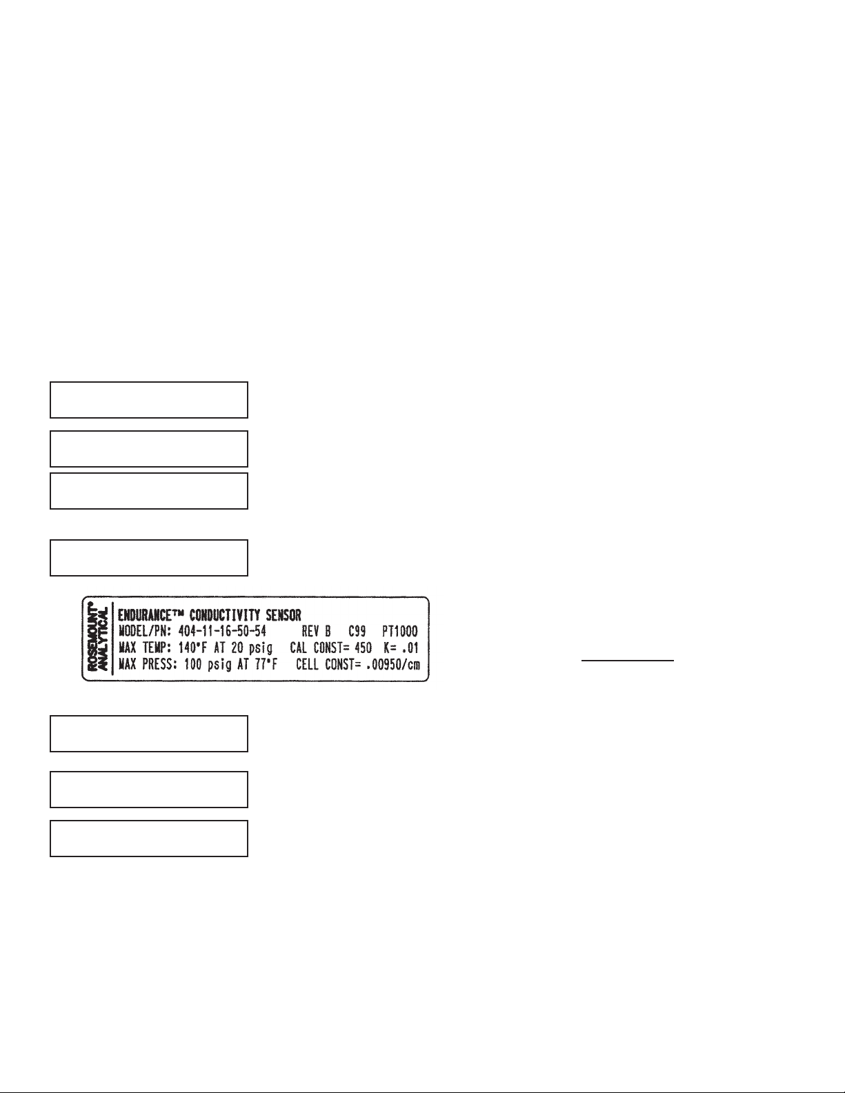
7. Enter the cell constant. See label attached to sensor.
8. Choose temperature units: °C or °F.
9. If you selected Custom, you must enter the appropriate conductivity and concentration data points. From the main display, press MENU. Choose Program fol-
lowed by Measurement and Custom. The screen shown at left appears. Select
Enter Data Pts. Follow the prompts and enter the display units, the number of
data points, and enter the concentration and conductivity data points. Enter the
reference temperature and the temperature coefficient (slope). Once the analyzer has been configured, press EXIT. For a guide to the program menu, see the
menu trees on pages 5 & 6.
10. To change output settings, to scale the 4-20 mA output, to change measurementrelated settings from the default values, and to set security codes, press MENU.
Select Program and follow the prompts. Refer to the menu tree on pages 5 & 6.
11. To return the transmitter to default settings, choose ResetAnalyzer in the
Program menu.
Enter Data Pts
Ref Temp Slope
Cell Constant?
1.0000/cm
Temperature in?
° C ° F
Concentration
Units?
% ppm none
1. Refer to page 11 for installation instructions.
2. Wire conductivity sensor to the transmitter. Refer to the sensor instruction sheet for details.
3. Once connections are secure and verified, apply DC power to the transmitter.
4. When the transmitter is powered up for the first time, Quick Start screens appear. Using Quick Start is easy.
a. A blinking field shows the position of the cursor.
b. Use the t or u key to move the cursor left or right. Use the p or q key to move the cursor up or down or to
increase or decrease the value of a digit. Use the p or q key to move the decimal point.
c. Press ENTER to store a setting. Press EXIT to leave without storing changes. Pressing EXIT also returns the
display to the previous screen.
&
If there is no cell constant on the label, calculate it
from the equation:
cell const = K
500 + cal const
1000
e
j
Measure?
Cond
Resistivity >>
Measure?
TDS Custom >>
English
Français
Español >>


i
MODEL XMT-C TABLE OF CONTENTS
MODEL XMT-C TWO-WIRE CONDUCTIVITY TRANSMITTER
TABLE OF CONTENTS
Section Title Page
1.0 DESCRIPTION AND SPECIFICATIONS ................................................................ 1
1.1 Features and Applications........................................................................................ 1
1.2 Specifications........................................................................................................... 2
1.3 Hazardous Location Approval.................................................................................. 4
1.4 Menu Tree for Model XMT-C-HT.............................................................................. 5
1.5 Menu Tree for Model XMT-C-FF .............................................................................. 6
1.6 HART Communications............................................................................................ 7
1.7 FOUNDATION Fieldbus .............................................................................................. 7
1.8 Asset Management Solutions ................................................................................. 8
1.9 Ordering Information ............................................................................................... 10
1.10 Accessories ............................................................................................................. 10
2.0 INSTALLATION ....................................................................................................... 11
2.1 Unpacking and Inspection........................................................................................ 11
2.2 Installation................................................................................................................ 11
3.0 WIRING.................................................................................................................... 15
3.1 Power Supply / Current Loop — Model XMT-C-HT ................................................. 15
3.2 Power Supply Wiring for Model XMT-C-FF.............................................................. 16
3.2 Sensor Wiring .......................................................................................................... 17
4.0 INTRINSICALLY SAFE INSTALLATION................................................................. 18
5.0 DISPLAY AND OPERATION................................................................................... 36
5.1 Display ..................................................................................................................... 36
5.2 Keypad..................................................................................................................... 36
5.3 Programming and Calibrating the Model Xmt — Tutorial......................................... 37
5.4 Menu Trees.............................................................................................................. 38
5.5 Diagnostic Messages............................................................................................... 38
5.6 Security .................................................................................................................... 41
5.7 Using Hold ............................................................................................................... 41
6.0 OPERATION WITH MODEL 375............................................................................. 42
6.1 Note on Model 375 HART and Foundation Fieldbus Communicator....................... 42
6.2 Connecting the HART and Foundation Fieldbus Communicator ............................. 42
6.3 Operation ................................................................................................................. 43
7.0 CALIBRATION — TEMPERATURE........................................................................ 47
7.1 Introduction .............................................................................................................. 47
7.2 Calibrating Temperature........................................................................................... 47
8.0 CALIBRATION — CONDUCTIVITY ....................................................................... 48
8.1 Introduction .............................................................................................................. 48
8.2 Entering the Cell Constant ....................................................................................... 49
8.3 Zeroing the Instrument............................................................................................. 50
8.4 Calibrating the Sensor in a Conductivity Standard................................................... 51
8.5 Calibrating the Sensor to a Laboratory Instrument .................................................. 52

MODEL XMT-C TABLE OF CONTENTS
TABLE OF CONTENTS CONT’D
ii
9.0 PROGRAMMING THE TRANSMITTER.................................................................. 53
9.1 General .................................................................................................................... 53
9.2 Changing Start-up Settings...................................................................................... 53
9.3 Configuring and Ranging the Output ....................................................................... 54
9.4 Choosing and Configuring the Analytical Measurement .......................................... 57
9.5 Choosing Temperature Units & Manual or Automatic Temperature Compensation. 58
9.6 Setting a Security Code ........................................................................................... 59
9.7 Making HART-related Settings................................................................................. 60
9.8 Resetting Factory Calibration and Factory Default Settings .................................... 60
9.9 Selecting a Default Screen and Screen Contrast .................................................... 61
10.0 MAINTENANCE ...................................................................................................... 62
10.1 Overview .................................................................................................................. 62
10.2 Replacement Parts .................................................................................................. 62
11.0 THEORY OF OPERATION ...................................................................................... 63
11.1 Conductivity / Resistivity / % Concentration............................................................. 63
11.2 Temperature Correction ........................................................................................... 63
12.0 THEORY — REMOTE COMMUNICATIONS........................................................... 65
12.1 Overview of HART Communications........................................................................ 65
12.2 HART Interface Devices........................................................................................... 65
12.2 Asset Management Solutions .................................................................................. 66
13.0 RETURN OF MATERIAL......................................................................................... 67

MODEL XMT-C TABLE OF CONTENTS
LIST OF FIGURES
Number Title Page
1-1 Menu Tree — XMT-C-HT ......................................................................................... 5
1-2 Menu Tree — XMT-C-FF.......................................................................................... 6
1-3 Configuring Model XMT Transmitter with FOUNDATION Fieldbus .............................. 7
1-4 HART and FOUNDATION Fieldbus Communicators ................................................... 8
1-5 AMS Main Menu Tools ............................................................................................. 9
2-1 Removing the Knockouts ......................................................................................... 11
2-2 Power Supply / Current Loop Wiring ........................................................................ 11
2-3 Panel Mount Installation ........................................................................................... 12
2-4 Pipe Mount Installation ............................................................................................. 13
2-5 Surface Mount Installation........................................................................................ 14
3-1 Load/Power Supply Requirements........................................................................... 15
3-2 Power Supply / Current Loop Wiring ........................................................................ 15
3-3 Typical Fieldbus Network Electrical Wiring Configuration ........................................ 16
3-4 Loop Power and Sensor Wiring................................................................................ 16
4-1 FM Intrinsically Safe Label for Model XMT-C-HT..................................................... 18
4-2 FM Intrinsically Safe Installation for Model XMT-C-HT............................................. 19
4-3 CSA Intrinsically Safe Label for Model XMT-C-HT ................................................... 20
4-4 CSA Intrinsically Safe Installation for Model XMT-C-HT........................................... 21
4-5 ATEX Intrinsically Safe Label for Model XMT-C-HT ................................................. 22
4-6 ATEX Intrinsically Safe Installation for Model XMT-C-HT......................................... 23
4-7 FM Intrinsically Safe Label for Model XMT-C-FF ..................................................... 24
4-8 FM Intrinsically Safe Installation for Model XMT-C-FF ............................................. 25
4-9 CSA Intrinsically Safe Label for Model XMT-C-FF ................................................... 26
4-10 CSA Intrinsically Safe Installation for Model XMT-C-FF ........................................... 27
4-11 ATEX Intrinsically Safe Label for Model XMT-C-FF ................................................. 28
4-12 ATEX Intrinsically Safe Installation for Model XMT-C-FF ......................................... 29
4-13 FM Intrinsically Safe Label for Model XMT-C-FI....................................................... 30
4-14 FM Intrinsically Safe Installation for Model XMT-C-FI .............................................. 31
4-15 CSA Intrinsically Safe Label for Model XMT-C-FI..................................................... 32
4-16 CSA Intrinsically Safe Installation for Model XMT-C-FI ............................................ 33
4-17 ATEX Intrinsically Safe Label for Model XMT-C-FI................................................... 34
4-18 ATEX Intrinsically Safe Installation for Model XMT-C-FI .......................................... 35
5-1 Displays During Normal Operation........................................................................... 36
5-2 Solu Comp Xmt Keypad ........................................................................................... 36
5-3 Menu Tree for Model XMT-C-HT .............................................................................. 39
5-4 Menu Tree for Model XMT-C-FF .............................................................................. 40
6-1 Connecting the Model 375 Communicator .............................................................. 42
6-2 XMT-C-HT HART / Model 375 Menu Tree................................................................ 44
12-1 HART Communicators ............................................................................................. 65
12-2 AMS Main Menu Tools ............................................................................................. 66

1
MODEL XMT-C SECTION 1.0
DESCRIPTION AND SPECIFICATIONS
SECTION 1.0
DESCRIPTION AND SPECIFICATIONS
Model Xmt Family of Two-wire Transmitters
• CHOICE OF COMMUNICATION PROTOCOLS:
HART
®
or FOUNDATION®Fieldbus
• CLEAR, EASY-TO-READ two-line display shows commissioning menus
and process measurement displays in English
• SIMPLE TO USE MENU STRUCTURE
• CHOICE OF PANEL OR PIPE/SURFACE MOUNTING
• NON-VOLATILE MEMORY retains program settings and calibration
data during power failures
• SIX LOCAL LANGUAGES - English, French, German, Italian, Spanish and Portuguese
1.1 FEATURES AND APPLICATIONS
The Solu Comp Model Xmt family of transmitters can be
used to measure pH, ORP, conductivity (using either contacting or toroidal sensors), resistivity, oxygen (ppm and
ppb level), free chlorine, total chlorine, monochloramine
and ozone in a variety of process liquids. The Xmt is compatible with most Rosemount Analytical sensors. See the
Specification sections for details.
The transmitter has a rugged, weatherproof, corrosionresistant enclosure (NEMA 4X and IP65). The panel mount
version fits standard ½ DIN panel cutouts, and its shallow
depth is ideally suited for easy mounting in cabinet-type
enclosures. A panel mount gasket is included to maintain
the weather rating of the panel. Surface/pipe mount enclosure includes self-tapping screws for surface mounting. A
pipe mounting accessory kit is available for mounting to a
2-inch pipe.
The transmitter has a two-line 16-character display. Menu
screens for calibrating and registering choices are simple
and intuitive. Plain language prompts guide the user
through the procedures. There are no service codes to
enter before gaining access to menus.
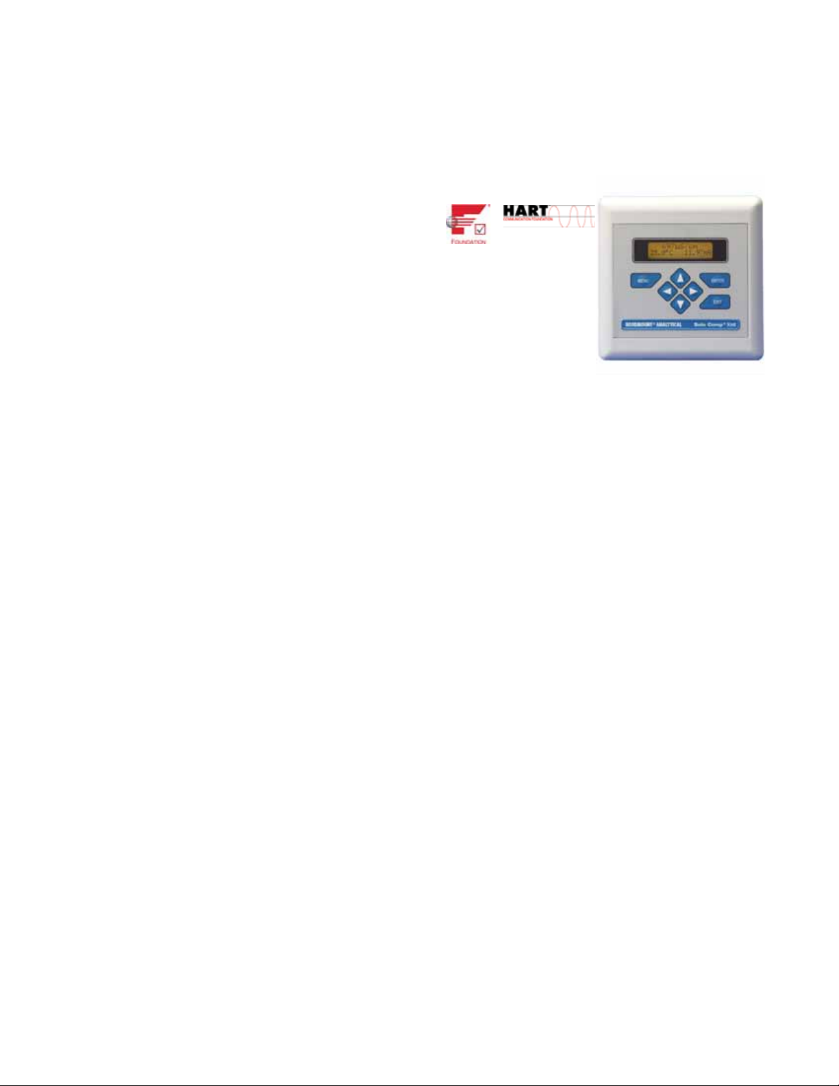
Two digital communication protocols are available: HART
(model option -HT) and F
OUNDATION fieldbus (model option
-FF or -FI). Digital communications allow access to AMS
(Asset Management Solutions). Use AMS to set up and
configure the transmitter, read process variables, and troubleshoot problems from a personal computer or host anywhere in the plant.
The seven-button membrane-type keypad allows local programming and calibrating of the transmitter. The HART
Model 375 communicator can also be used for programming and calibrating the transmitter.
The Model Xmt-C Transmitter with the appropriate sensor
measures dissolved oxygen (ppm and ppb level), free
chlorine, total chlorine, monochloramine, and ozone in
water and aqueous solutions. The transmitter is compatible with Rosemount Analytical 499A amperometric sensors for oxygen, chlorine, monochloramine, and ozone;
and with Hx438, Bx438, and Gx448 steam-sterilizable oxygen sensors.
For free chlorine measurements, both automatic and manual pH correction are available. pH correction is necessary
because amperometric free chlorine sensors respond only
to hypochlorous acid, not free chlorine, which is the sum of
hypochlorous acid and hypochlorite ion. To measure free
chlorine, most competing instruments require an acidified
sample. Acid lowers the pH and converts hypochlorite ion
to hypochlorous acid. The Model Xmt-C eliminates the
need for messy and expensive sample conditioning by
measuring the sample pH and using it to correct the chlorine sensor signal. If the pH is relatively constant, a fixed
pH correction can be used, and the pH measurement is
not necessary. If the pH is greater than 7.0 and fluctuates
more than about 0.2 units, continuous measurement of pH
and automatic pH correction is necessary. See
Specifications section for recommended pH sensors.
Corrections are valid to pH 9.5.
The transmitter fully compensates oxygen, ozone, free
chlorine, total chlorine, and monochloramine readings for
changes in membrane permeability caused by temperature changes.
For pH measurements — pH is available with free chlorine
only — the Xmt-C features automatic buffer recognition
and stabilization check. Buffer pH and temperature data
for commonly used buffers are stored in the transmitter.
Glass impedance diagnostics warn the user of an aging or
failed pH sensor.
2
MODEL XMT-C SECTION 1.0
DESCRIPTION AND SPECIFICATIONS
1.2 SPECIFICATIONS
1.2.1 GENERAL SPECIFICATIONS
Case: ABS (panel mount), polycarbonate (pipe/wall mount);
NEMA 4X/CSA 4 (IP65)
Dimensions
Panel (code -10): 6.10 x 6.10 x 3.72 in. (155 x
155 x 94.5 mm)
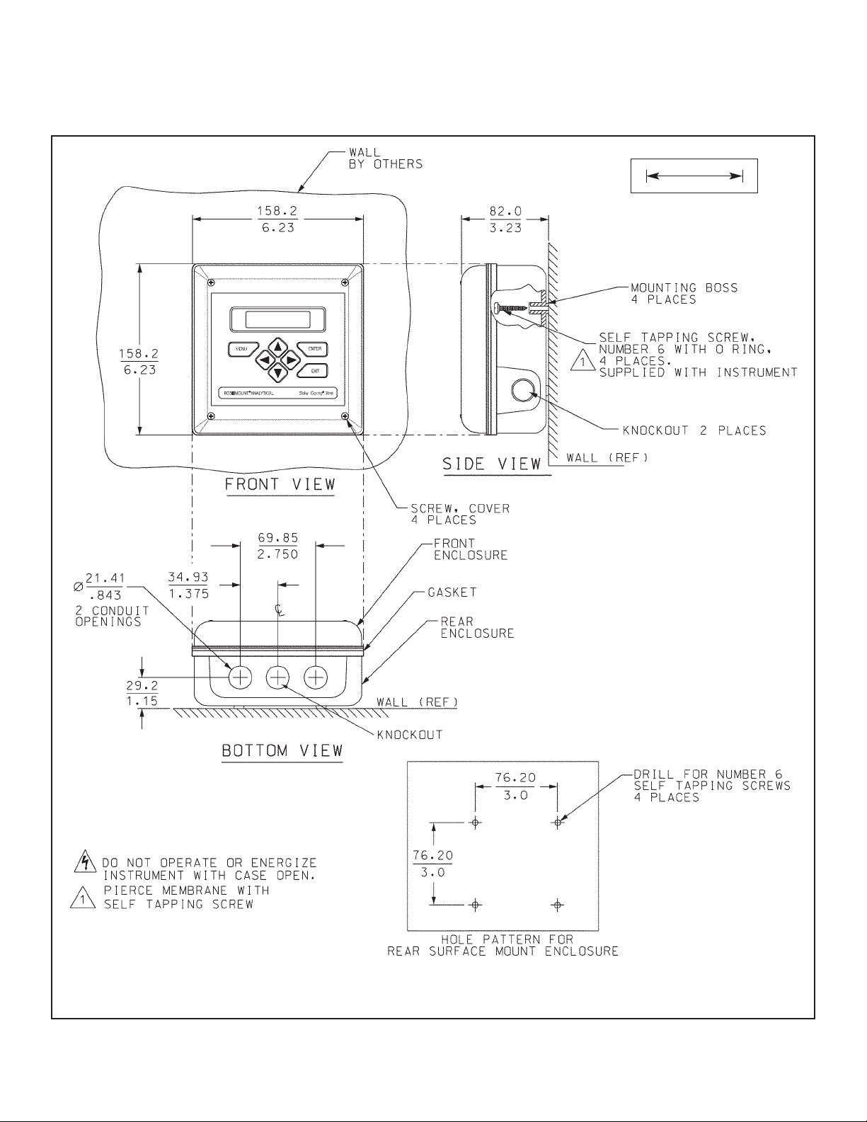
Surface/Pipe (code -11): 6.23 x 6.23 x 3.23 in. (158
x 158 x 82 mm); see page 15 for dimensions of pipe
mounting bracket.
Conduit openings: Accepts PG13.5 or 1/2 in. conduit fit-
tings
Ambient Temperature: 32 to 122°F (0 to 50°C). Some
degradation of display above 50°C.
Storage Temperature: -4 to 158°F (-20 to 70°C)
Relative Humidity: 10 to 90% (non-condensing)
Weight/Shipping Weight: 2 lb/3 lb (1 kg/1.5 kg)
Display: Two line, 16-character display. Character height:
4.8 mm; first line shows process variable, second line
shows process temperature and output current. Fault
and warning messages, when triggered, alternate with
temperature and output readings.
During calibration and programming, messages,
prompts, and editable values appear on the two-line
display.
Temperature resolution: 0.1°C (≤99.9°C);
1°C (≥100°C)
Hazardous Location Approval: For details, see specifi-
cations for the measurement of interest.
RFI/EMI: EN-61326
DIGITAL COMMUNICATIONS:
HART —
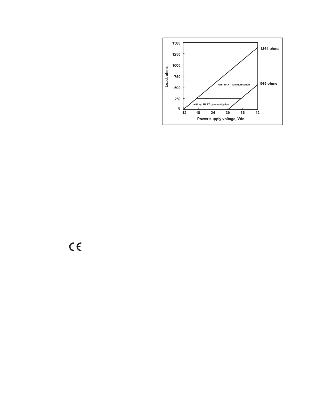
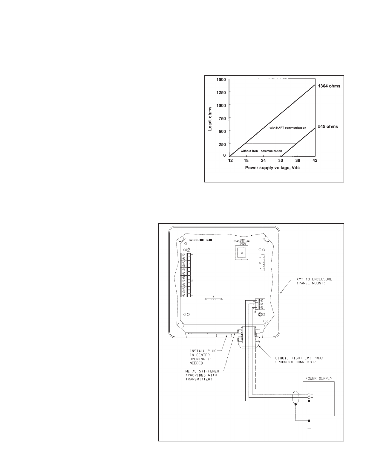
Power & Load Requirements: Supply voltage at the
transmitter terminals should be at least 12 Vdc.
Power supply voltage should cover the voltage
drop on the cable plus the external load resistor
required for HART communications (250 Ω minimum). Minimum power supply voltage is 12 Vdc.
Maximum power supply voltage is 42.4 Vdc. The
graph shows the supply voltage required to
maintain 12 Vdc (upper line) and 30 Vdc (lower
line) at the transmitter terminals when the current is 22 mA.
Analog Output: Two-wire, 4-20 mA output with
superimposed HART digital signal. Fully scalable
over the operating range of the sensor.
Output accuracy: ±0.05 mA
F
OUNDATION fieldbus —
Power & Load Requirements: A power supply volt-
age of 9-32 Vdc at 13 mA is required.
Fieldbus Intrinsically Safe COncept/FISCO-compliant
versions of Model Xmt Foundation Fieldbus transmitters are available.
Solu Comp is a trademark of Rosemount Analytical.
Xmt is a trademark of Rosemount Analytical.
HART is a registered trademark of the HART Communication Foundation.
FOUNDATION is a registered trademark of Fieldbus Foundation.
MODEL XMT-C SECTION 1.0
DESCRIPTION AND SPECIFICATIONS
3
1.2.2 FUNCTIONAL SPECIFICATIONS
Automatic Temperature Compensation:
3-wire Pt 100 or Pt 1000 RTD
Conductivity: 0 to 200°C (32 to 392°F)
Resistivity: 0 to 100°C (32 to 212°F)
Low Conductivity: 0 to 100°C (32 to 212°F)
Diagnostics: The internal diagnostics can detect:
Calibration Error ROM Failure
Temperature Slope Error Zero Error
High Temperature Warning CPU Failure
Low Temperature Warning Input Warning
Once one of the above is diagnosed, the Xmt-C will
display a message describing the problem.
Digital Communications:
HART: PV, SV, and TV assignable to measurement
(conductivity, resistivity, or concentration), temperature, and raw conductivity. Raw conductivity is measured conductivity before temperature correction.
Fieldbus: Three AI blocks assignable to measurement
(conductivity, resistivity, or concentration), temperature, and raw conductivity. Raw conductivity is measured conductivity before temperature correction.
Execution time 75 msec. One PID block; execution
time 150 msec. Device type: 4084. Device revision: 1.
Certified to ITK 4.5.
1.2.3 TRANSMITTER SPECIFICATIONS @ 25°C
Measured Range: 0-20,000 µS/cm
Accuracy: ± 0.7% of reading and ± 0.002 µS/cm
Repeatability: ± 0.25% of reading
Temperature Accuracy: ± 0.2°C between 0 and 50°C;
± 0.5°C above 50°C (excludes inaccuracies in sensor)
Temperature Compensation: Slope 0-5%/°C, ultra-pure
water, cation conductivity, or raw (uncompensated)
conductivity.
Compatible RTD: 100Ω or 1000Ω with automatic recogni-
tion
Ambient Temperature Coefficient:
± 0.05% of reading/°C
Maximum Cable Length: 200 ft (61 m)
1.2.4 LOOP SPECIFICATIONS
Accuracy: under controlled laboratory conditions at 25°C
(77°F) with perfectly calibrated ENDURANCE sensor of
appropriate cell constant:
Calibration: Calibrate against previously calibrated stan-
dard sensor and analyzer, or calibrate against solution
of known conductivity.
1.2.5 SENSOR SELECTION GUIDELINES
Note: The conductivity values shown in the above chart are for
UNCOMPENSATED (or RAW) conductivity at 25°C.
Maximum range values will vary due to temperature compensation selection, process temperature, and other process
conditions.
RECOMMENDED SENSORS:
Model 140 Retractable Conductivity
Model 141 Insertion High Conductivity
Model 142 Insertion Low Conductivity
Model 150 Insertion/Submersion Conductivity
Model 400/VP Screw-In Low Conductivity
Model 401 Screw-In High Conductivity
Model 402/VP Retractable Conductivity
Model 403/VP Sanitary Conductivity
Model 404 Low Flow Conductivity
Cell Constant Range Loop accuracy
0.01/cm up to 50 µS/cm ±0.7% of reading
±0.002 µS/cm
0.1/cm 0.4 to 50 µS/cm ±0.7% of reading
50 to 200 µS/cm ±2% of reading
1.0/cm 4 to 5000 µS/cm ±0.7% of reading
5000 to 20,000 µS/cm ±2% of reading
Cell Constant Suggested Conductivity Range
0.01/cm up to 50 µS/cm
0.1/cm 0.4 to 500 µS/cm
1.0/cm 4 to 20,000 µS/cm

4
MODEL XMT-C SECTION 1.0
DESCRIPTION AND SPECIFICATIONS
1.3 HAZARDOUS LOCATION APPROVALS
Intrinsic Safety:
Class I, II, III, Div. 1
Groups A-G
T4 Tamb = 50°C
Class I, II, III, Div. 1
Groups A-G
T4 Tamb = 50°C
ATEX 1180
II 1 G
Baseefa04ATEX0214X
EEx ia IIC T4
Tamb = 0°C to 50°C
Non-Incendive:
Class I, Div. 2, Groups A-D
Dust Ignition Proof
Class II & III, Div. 1, Groups E-G
NEMA 4/4X Enclosure
Class I, Div. 2, Groups A-D
Dust Ignition Proof
Class II & III, Div. 1, Groups E-G
NEMA 4/4X Enclosure
T4 Tamb = 50°C
MODEL XMT-C SECTION 1.0
DESCRIPTION AND SPECIFICATIONS
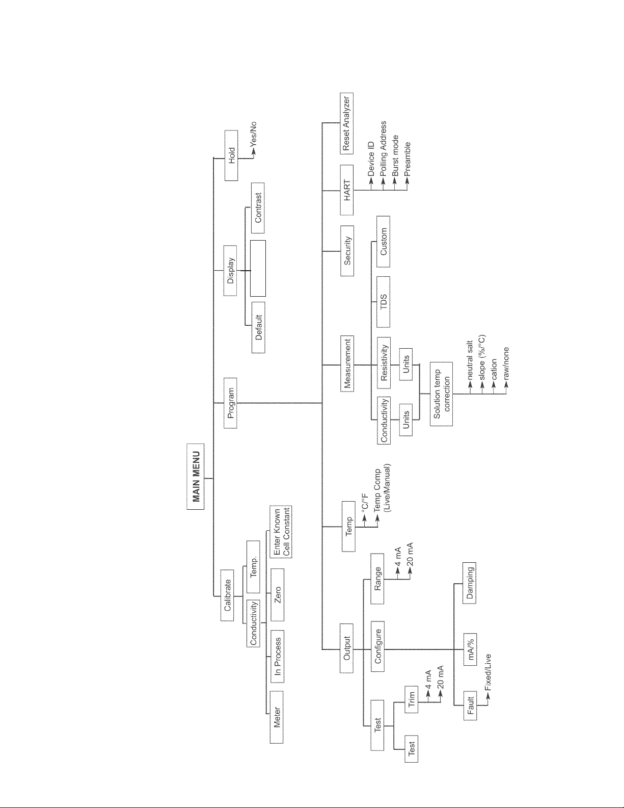
FIGURE 1-1. MENU TREE FOR MODEL SOLU COMP XMT-C-HT TRANSMITTER
1.4 MENU TREE FOR MODEL XMT-C-HT
5
Language
MODEL XMT-C SECTION 1.0
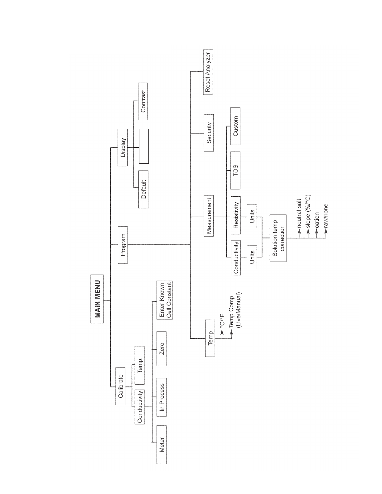
DESCRIPTION AND SPECIFICATIONS
FIGURE 1-2. MENU TREE FOR MODEL SOLU COMP XMT-C-FF TRANSMITTER
1.5 MENU TREE FOR MODEL XMT-C-FF
6
Language
7
MODEL XMT-C SECTION 1.0
DESCRIPTION AND SPECIFICATIONS
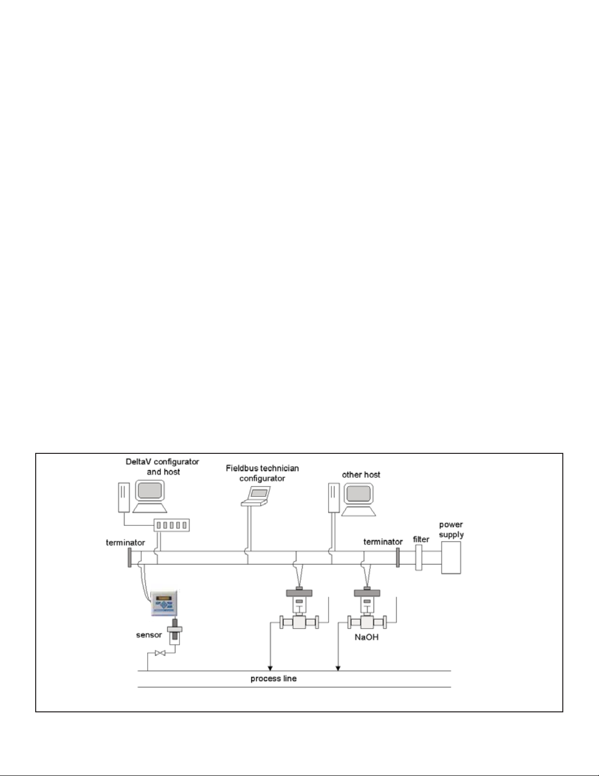
1.7 FOUNDATION FIELDBUS
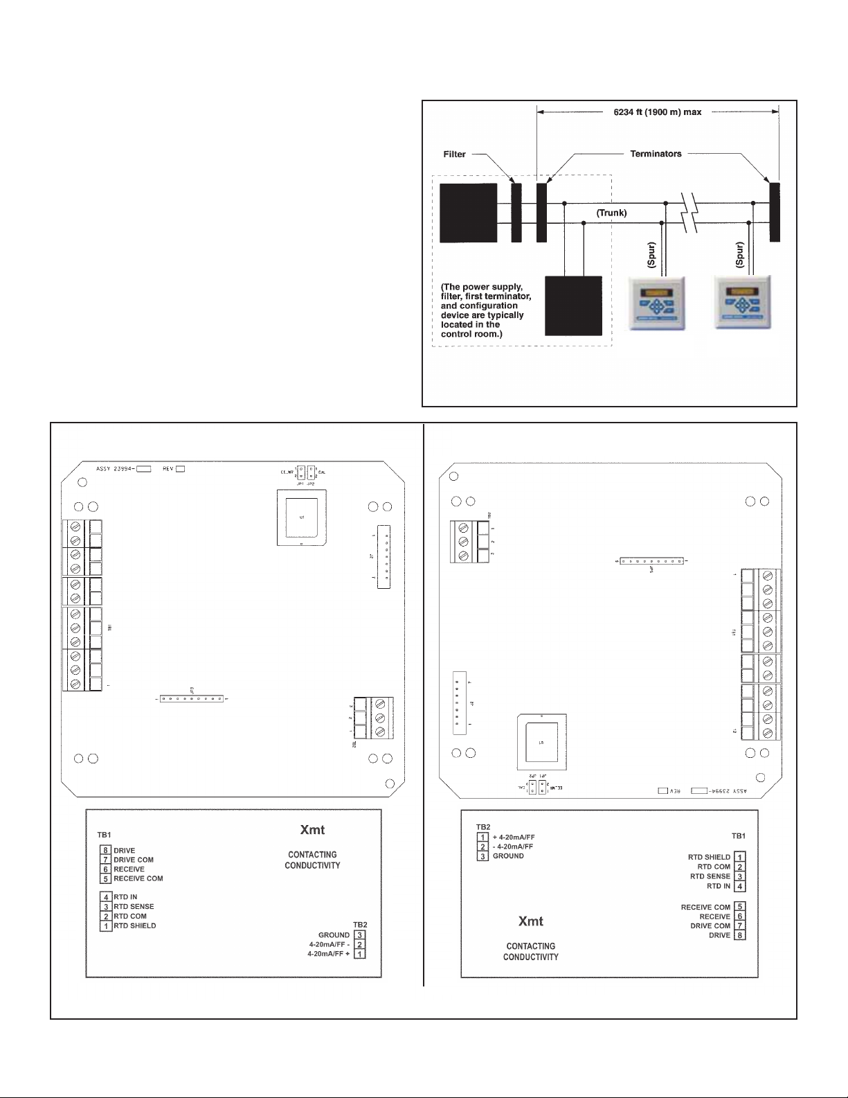
Figure 1-3 shows a Xmt-C-FF being used to measure conductivity. The figure also shows three ways in which Fieldbus
communication can be used to read process variables and configure the transmitter.
FIGURE 1-3. CONFIGURING MODEL XMT-C TRANSMITTER WITH FOUNDATION FIELDBUS
1.6 HART COMMUNICATIONS
1.6.1 OVERVIEW OF HART COMMUNICATION
HART (highway addressable remote transducer) is a digital communication system in which two frequencies are superimposed on the 4 to 20 mA output signal from the transmitter. A 1200 Hz sine wave represents the digit 1, and a 2400 Hz
sine wave represents the digit 0. Because the average value of a sine wave is zero, the digital signal adds no dc component to the analog signal. HART permits digital communication while retaining the analog signal for process control.
The HART protocol, originally developed by Fisher-Rosemount, is now overseen by the independent HART
Communication Foundation. The Foundation ensures that all HART devices can communicate with one another. For more
information about HART communications, call the HART Communication Foundation at (512) 794-0369. The internet
address is http://www.hartcomm.org.
1.6.2 HART INTERFACE DEVICES
The Model 375 HART Communicator is a hand-held device that provides a common link to all HART SMART instruments and allows access to AMS (Asset Management Solutions). Use the HART communicator to set up and control the
XMT-C-HT and to read measured variables. Press ON to display the on-line menu. All setup menus are available
through this menu.
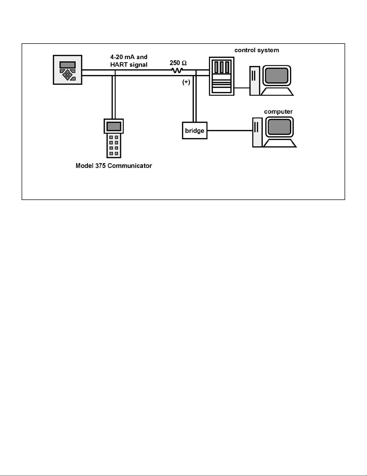
HART communicators allow the user to view measurement data (conductivity, TDS, resistivity, and temperature), program
the transmitter, and download information from the transmitter for transfer to a computer for analysis. Downloaded information can also be sent to another HART transmitter. Either a hand-held communicator, such as the Rosemount Model 375, or
a computer can be used. HART interface devices operate from any wiring termination point in the 4 - 20 mA loop. A minimum load of 250 ohms must be present between the transmitter and the power supply. See Figure 1-4.
If your communicator does not recognize the Model XMT-C transmitter, the device description library may need updating.
Call the manufacturer of your HART communication device for updates.
XMT-C-FF
conductivity
HCl
8
MODEL XMT-C SECTION 1.0
DESCRIPTION AND SPECIFICATIONS
FIGURE 1-4. HART and FOUNDATION™ Fieldbus Communicators.
Both the Rosemount Model 375 (or 275) and a computer can be used to communicate with a HART transmitter. The 250 ohm load
(minimum) must be present between the transmitter and the power supply.
1.8 ASSET MANAGEMENT SOLUTIONS
Asset Management Solutions (AMS) is software that helps plant personnel better monitor the performance of analytical
instruments, pressure and temperature transmitters, and control valves. Continuous monitoring means maintenance personnel can anticipate equipment failures and plan preventative measures before costly breakdown maintenance is
required.
AMS uses remote monitoring. The operator, sitting at a computer, can view measurement data, change program settings,
read diagnostic and warning messages, and retrieve historical data from any HART-compatible device, including the Model
XMT-C transmitter. Although AMS allows access to the basic functions of any HART compatible device, Rosemount
Analytical has developed additional software for that allows access to all features of the Model Xmt-C transmitter.
AMS can play a central role in plant quality assurance and quality control. Using AMS Audit Trail, plant operators can track
calibration frequency and results as well as warnings and diagnostic messages. The information is available to Audit Trail
whether calibrations were done using the infrared remote transmitter, the Model 375 HART communicator, or AMS software.
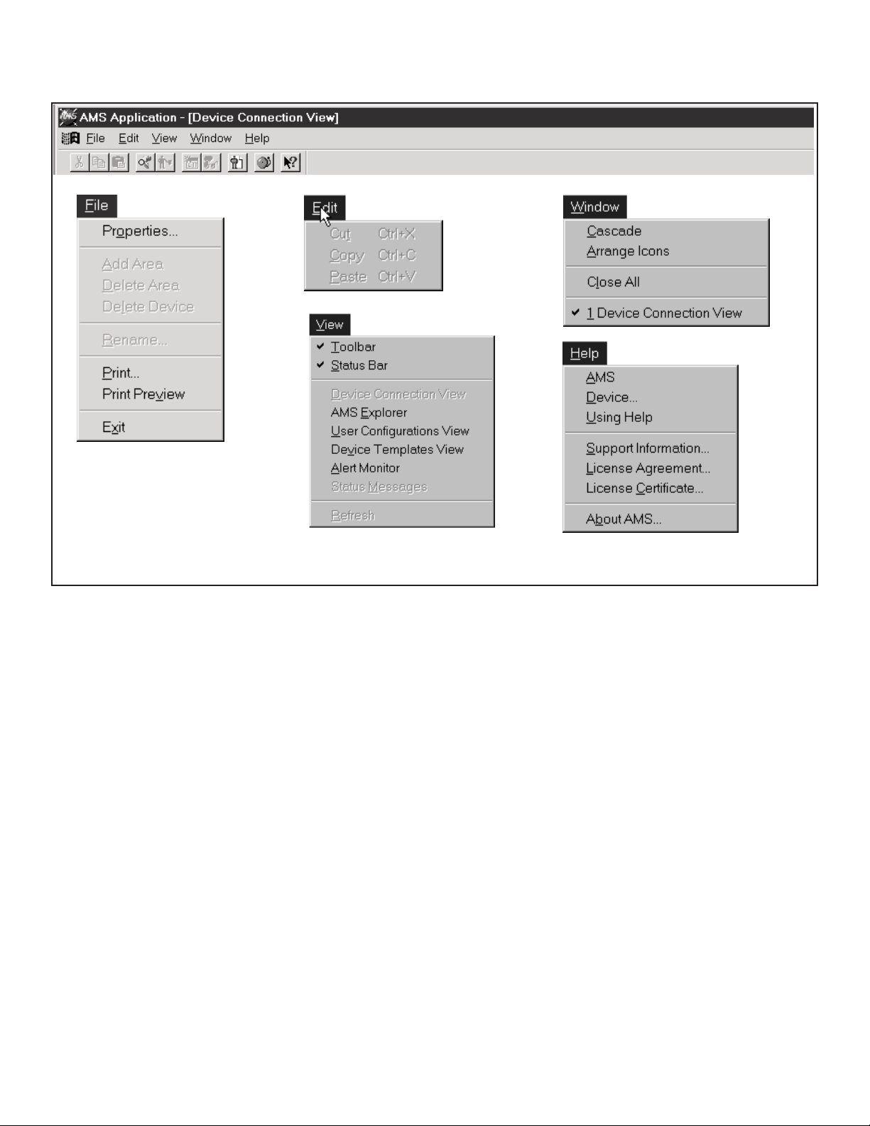
AMS operates in Windows 2000, NT, and XP operating systems. See Figure 1-5 for a sample screen. AMS communicates
through a HART-compatible modem with any HART transmitters, including those from other manufacturers. AMS is also
compatible with FOUNDATION Fieldbus, which allows future upgrades to Fieldbus instruments.
Rosemount Analytical AMS windows provide access to all transmitter measurement and configuration variables. The
user can read raw data, final data, and program settings and can reconfigure the transmitter from anywhere in the plant.
Model XMT-C
MODEL XMT-C SECTION 1.0
DESCRIPTION AND SPECIFICATIONS
FIGURE 1-5. AMS MAIN MENU TOOLS
9

10
MODEL XMT-C SECTION 1.0
DESCRIPTION AND SPECIFICATIONS
1.10 ACCESSORIES
POWER SUPPLY: Use the Model 515 Power Supply to provide dc loop power to the transmitter. The Model 515 pro-
vides two isolated sources at 24Vdc and 200 mA each. For more information refer to product data sheet 71-515.
ALARM MODULE: The Model 230A alarm Module receives the 4-20 mA signal from the XMT-C-HT transmitter and acti-
vates two alarm relays. High/high, low/low, and high/low are available. Hysteresis (deadband) is also adjustable. For
more information, refer to product data sheet 71-230A.
HART COMMUNICATOR: The Model 375 HART communicator allows the user to view measurement values as well as
to program and configure the transmitter. The Model 375 attaches to any wiring terminal across the output loop. A
minimum 250 Ω load must be between the power supply and transmitter. Order the Model 375 communicator from
Emerson Process Management. Call (800) 999-9307.
1.9 ORDERING INFORMATION
The Solu Comp Model Xmt Two-Wire Transmitter is intended for conductivity and resistivity measurements using con-
tacting conductivity sensors.
ACCESSORIES
MODEL/PN DESCRIPTION
515 DC loop power supply (see product data sheet 71-515)
230A Alarm module (see product data sheet 71-230A)
23820-00 2-in. pipe mounting kit
9240048-00 Stainless steel tag, specify marking
23554-00 Gland fittings PG 13.5, 5 per package
CODE REQUIRED SELECTION
HT Analog 4-20 mA output with superimposed HART digital signal
FF Foundation fieldbus digital output
FI Foundation fieldbus digital output with FISCO
CODE REQUIRED SELECTION
10 Panel mounting enclosure
11 Pipe/Surface mounting enclosure (pipe mounting requires accessory kit PN 23820-00)
CODE AGENCY APPROVALS
60 No approval
67 FM approved intrinsically safe and non-incendive (when used with appropriate sensor and safety barrier)
69 CSA approved intrinsically safe and non-incendive (when used with appropriate sensor and safety barrier)
73 ATEX approved intrinsically safe (when used with appropriate sensor and safety barrier)
CODE REQUIRED SELECTION
P pH/ORP
MODEL
Xmt SMART TWO-WIRE MICROPROCESSOR TRANSMITTER
Xmt-P-HT-10-67 EXAMPLE
11
MODEL XMT-C SECTION 2.0
INSTALLATION
SECTION 2.0
INSTALLATION
2.1 Unpacking and Inspection
2.2 Installation
2.1 UNPACKING AND INSPECTION
Inspect the shipping container. If it is damaged, contact the shipper immediately for instructions. Save the box. If there is no apparent damage, remove
the transmitter. Be sure all items shown on the packing list are present. If
items are missing, immediately notify Rosemount Analytical.
Save the shipping container and packaging. They can be reused if it is later
necessary to return the transmitter to the factory.
2.2 INSTALLATION
1. Although the transmitter is suitable for outdoor use, do not install it in
direct sunlight or in areas of extreme temperatures.
2. Install the transmitter in an area where vibrations and electromagnetic
and radio frequency interference are minimized or absent.
3. Keep the transmitter and sensor wiring at least one
foot from high voltage conductors. Be sure there is
easy access to the transmitter.
4. The transmitter is suitable for panel (Figure 2-3), pipe
(Figure 2-4), or surface (Figure 2-5) mounting.
5. The transmitter case has two 1/2-inch (PG13.5) conduit openings and either three or four 1/2-inch knockouts. The panel mount XMT-C-HT has four knockouts.
The pipe/surface mount transmitter has three knockouts*. One conduit opening is for the power/output
cable; the other opening is for the sensor cable.
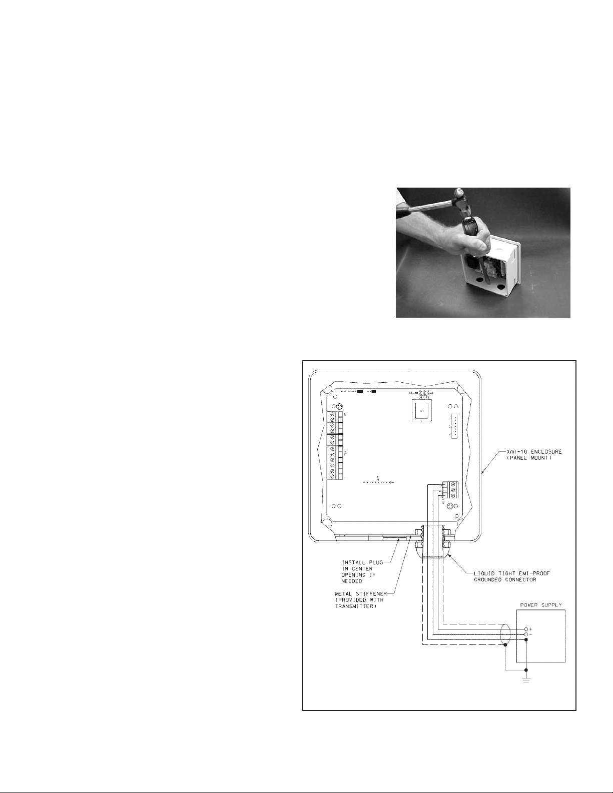
Figure 1 shows how to remove a knockout. The knockout grooves are on the outside of the case. Place the
screwdriver blade on the inside of the case and align it
approximately along the groove. Rap the screwdriver
sharply with a hammer until the groove cracks. Move
the screwdriver to an uncracked portion of the groove
and continue the process until the knockout falls out.
Use a small knife to remove the flash from the inside
of the hole.
6. Use weathertight cable glands to keep moisture out to
the transmitter. If conduit is used, plug and seal the
connections at the transmitter housing to prevent
moisture from getting inside the instrument.
7. To reduce the likelihood of stress on wiring connections, do not remove the hinged front panel (-11 models) from the base during wiring installation. Allow sufficient wire leads to avoid stress on conductors.
*NEMA plug may be supplied instead of knockout for
pipe/surface version.
FIGURE 2-1. Removing the Knockouts
FIGURE 2-2. Power Supply/Current Loop Wiring

12
MODEL XMT-C SECTION 2.0
INSTALLATION
FIGURE 2-3. Panel Mount Installation
Access to the wiring terminals is through the rear cover. Four screws hold the cover in place.
Panel Mounting.
MILLIMETER
INCH
13
MODEL XMT-C SECTION 2.0
INSTALLATION
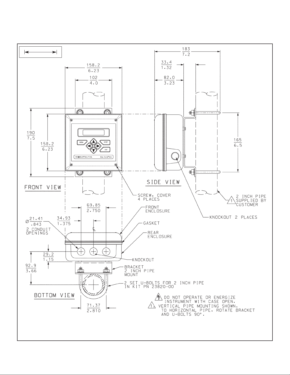
FIGURE 2-4. Pipe Mount Installation
The front panel is hinged at the bottom. The panel swings down for access to the wiring terminals.
Pipe Mounting.
MILLIMETER
INCH
14
MODEL XMT-C SECTION 2.0
INSTALLATION
FIGURE 2-5. Surface Mount Installation
The front panel is hinged at the bottom. The panel swings down for access to the wiring terminals.
Surface Mounting.
MILLIMETER
INCH
15
MODEL XMT-C SECTION 3.0
WIRING
3.1 POWER SUPPLY/CURRENT LOOP —
MODEL XMT-C-HT
3.1.1 Power Supply and Load Requirements.
Refer to Figure 3-1.
The supply voltage must be at least 12.0 Vdc at the transmitter terminals. The power supply must be able to cover the voltage drop on
the cable as well as the load resistor (250 Ω minimum) required for
HART communications. The maximum power supply voltage is
42.0 Vdc. For intrinsically safe installations, the maximum power
supply voltage is 30.0 Vdc. The graph shows load and power supply requirements. The upper line is the power supply voltage needed to provide 12 Vdc at the transmitter terminals for a 22 mA current. The lower line is the power supply voltage needed to provide
30 Vdc for a 22 mA current.
The power supply must provide a surge current during the first 80 milliseconds of startup. The maximum current is about
24 mA.
For digital communications, the load must be at least 250 ohms. To supply the 12.0 Vdc lift off voltage at the transmitter,
the power supply voltage must be at least 17.5 Vdc.
FIGURE 3-1. Load/Power Supply Requirements
FIGURE3-2. Power Supply/Current Loop Wiring
3.1.2 Power Supply-Current Loop Wiring.
For general purpose areas, wire power as
shown in Figure 3-2. For hazardous areas,
please see hazardous area installation drawings.
Run the power/signal wiring through the opening nearest TB-2.
For optimum EMI/RFI protection . . .
1. Use shielded power/signal cable and ground
the shield at the power supply.
2. Use a metal cable gland and be sure the
shield makes good electrical contact with the
gland.
3. Use the metal backing plate when attaching
the gland to transmitter enclosure.
The power/signal cable can also be enclosed in
an earth-grounded metal conduit.
Do not run power supply/signal wiring in the
same conduit or cable tray with AC power lines
or with relay actuated signal cables. Keep
power supply/signal wiring at least 6 ft (2 m)
away from heavy electrical equipment.
SECTION 3.0
WIRING
16
MODEL XMT-C SECTION 3.0
WIRING
3.2 POWER SUPPLY WIRING FOR
MODEL XMT-C-FF
3.2.1 Power Supply Wiring. For general purpose areas,
wire power as shown in Figure 3-4. For hazardous areas,
please see hazardous area installation drawings. Refer to
Figure 3-3 and Figure 3-4.
Run the power/signal wiring through the opening nearest
TB2. Use shielded cable and ground the shield at the
power supply. To ground the transmitter, attach the shield
to TB2-3.
NOTE
For optimum EMI/RFI immunity, the power supply/output cable should be shielded and enclosed
in an earth-grounded metal conduit.
Do not run power supply/signal wiring in the same conduit
or cable tray with AC power lines or with relay actuated
signal cables. Keep power supply/signal wiring at least
6 ft (2 m) away from heavy electrical equipment.
FIGURE 3-3. Typical Fieldbus Network Electrical
Wiring Configuration
XMT-C
Transmitter
XMT-C
Transmitter
FIGURE 3-4. Loop Power and Sensor Wiring
Panel Mount Pipe/Surface Mount

17
MODEL XMT-C SECTION 3.0
WIRING
3.3 SENSOR WIRING
Keep sensor wiring separate from power wiring. For best EMI/RFI protection, use shielded output signal cable in an
earth-grounded metal conduit. See Figure 3-4. Refer to the Instruction Sheet provided with each sensor for specific
wiring instructions.
3.1.1 WIRING THROUGH A JUNCTION BOX
The sensor can be wired to the analyzer through a remote junction box (PN 23550-00). Wire the extension cable and sensor cable point-to-point. See Figure 3-4. Refer to the sensor instruction manual for more details.
Factory-terminated (PN 23294-05) and unterminated (PN 9200276) connecting cable are available. The use of factory-terminated cable is strongly recommended. To prepare unterminated cable for use, follow the instructions in the sensor
instruction manual.
For maximum EMI/RFI protection, the outer braid of the sensor cable should be connected to the outer braided shield of
the extension cable. At the instrument, connect the outer braid of the extension cable to earth ground.
3.1.2 SENSOR SELECTION
All Rosemount Analytical contacting conductivity sensors with PT100 RTD or PT1000 RTD are compatible with the Model
Xmt-C transmitter. Refer to the Instruction Sheet provided with each sensor for specific wiring instructions.
Choose a contacting conductivity sensor that is appropriate for your process conditions and range of conductivity measurement.
TABLE 3-1. Model Xmt-C Sensor Selection
Cell Constant Range
0.01/cm 0 to 50 µS/cm
0.1/cm 1 to 500 µS/cm
1.0/cm 10 to 20,000 µS/cm

18
For FM Intrinsically Safe Label, see Figure 4-1.
For FM Intrinsically Safe Installation, see Figure 4-2.
For CSA Intrinsically Safe Label, see Figure 4-3.
For CSA Intrinsically Safe Installation, see Figure 4-4.
For ATEX Intrinsically Safe Label, see Figure 4-5.
For ATEX Intrinsically Safe Installation, see Figure 4-6.
MODEL XMT-C SECTION 4.0
INTRINSICALLY SAFE INSTALLATION
SECTION 4.0
INTRINSICALLY SAFE INSTALLATION
INTRINSICALLY SAFE INSTALLATIONS FOR MODEL XMT-C-HT
FIGURE 4-1. FM Intrinsically Safe Label for Model Xmt-C-HT

19
MODEL XMT-C SECTION 4.0
INTRINSICALLY SAFE INSTALLATION
FIGURE 4-2. FM Intrinsically Safe Installation for Model Xmt-C-HT

MODEL XMT-C SECTION 4.0
INTRINSICALLY SAFE INSTALLATION
FIGURE 4-3. CSA Intrinsically Safe Label for Model Xmt-C-HT
20

MODEL XMT-C SECTION 4.0
INTRINSICALLY SAFE INSTALLATION
FIGURE 4-4. CSA Intrinsically Safe Installation for Model Xmt-C-HT
21

MODEL XMT-C SECTION 4.0
INTRINSICALLY SAFE INSTALLATION
22
FIGURE 4-5. ATEX Intrinsically Safe Label for Model Xmt-C-HT

MODEL XMT-C SECTION 4.0
INTRINSICALLY SAFE INSTALLATION
23
FIGURE 4-6. ATEX Intrinsically Safe Installation for Model Xmt-C-HT

24
FIGURE 4-7. FM Intrinsically Safe Label for Model Xmt-C-FF
9241566-00
B
CHK
DATE
BY
REVISIONS
DESCRIPTION
THIS DOCUMENT IS
CERTIFIED BY
A
FM
06-01
A
QTY
REV
REV
REV
REV
REV
REV
W/O AGENCY APPROVAL
REVISIONS NOT PERMITTED
2400 Barranca Pkwy
Rosemount Analytical Division
Emerson Process Management,
Irvine, CA 92606
REV
12
SHEET OF
XMT-C-FF
LABEL, I.S. FM
DESCRIPTION
9241566-00
2:1
DWG NO
REV
RELEASE DATE ECO NO
ECO
LTR
10-6-04 9042 A
FM
APPROVED
10 /6 /04
10 /6 /04
J. FLOCK
PROJECT
CHECKED
2
10 /6 /04
J. FLOCK
THIS DWG CONVERTED TO
ENGR APVD
FINISH
B
SOLID EDGE
SIZE
SCALE
Emerson
TITLE
BILL OF MATERIAL
DATE
10/ 1/03
PART NO
B. JOHNSON
APPROVALS
R .060
4X
9241566-00/A
ITEM
TOLERANCES
UNLESS OTHERWISE SPECIFIED
.030
+
.XX
DRAWN
1/2
-
+
ANGLES
DIMENSIONS ARE IN INCHES
NOMINAL SURFACE FINISH 125
MACHINED FILLET RADII .020 MAX
.010
REMOVE BURRS & SHARP EDGES .020 MAX
-
-
+
.XXX
MATERIAL
to those who may compete with Rosemount Analytical.
Rosemount Analytical, and is n ot to be made available
This document contains information proprietary to
2.50
R
Rosemount Analytical
MODEL
XMT-C-FF-67
NORMAL OPERATING TEMPERATURE RANGE: 0-50vC
SUPPLY 9-32 VDC @ 22 mA
°CT4 Tamb = 50
INTRINSICALLY SAFE FOR CLASS I, II & III, DIVISION 1,
GROUPS A, B, C, D, E, F & G
HAZARDOUS AREA WHEN CONNECTED PER DWG. 1400244
1.50
NON-INCENDIVE CLASS I, DIVISION 2 GROUPS A, B, C & D
DUST IGNITION PROOF CLASS II AND III, DIVISION 1,
GROUPS E, F & G
WARNING: COMPONENT SUBSTITUTION MAY IMPAIR INTRINSIC
SAFETY OR SUITABILITY FOR DIVISION 2
NEMA 4/4X ENCLOSURE
4. NO CHANGE WITHOUT FM APPROVAL.
ON LABEL TO BE BLACK HELVETICA
MEDIUM. BACKGROUND TO BE WHITE.
3. ALL ALPHA AND NUMERIC CHARACTERS
(WHITE VINYL FACESTOCK) OR POLYESTER,
2 MATERIAL: 3M SCOTCHCAL #3650-10
SEE BLANK LABEL PN 9241406-01.
SUPER PREMIUM BLACK THERMAL TRANSFER RIBBON)
NOMENCLATURE TO BE PRINTED USING INTERMEC
PRESSURE SENSITIVE ACRYLIC ADHESIVE.
PN L7211210, 2 MIL GLOSS WHITE POLYESTER WITH
THICKNESS. PRESSURE SENSITIVE ADHESIVE,
(.002 REFERENCE THICKNESS CLEAR MATTE
FARSIDE AND SPLIT LINER) OR (INTERMEC
MYLAR OVERLAMINATE, .002-.005 FINISH
1. ARTWORK IS SHEET 2 OF 2.
NOTES: UNLESS OTHERWISE SPECIFIED

25
FIGURE 4-8. FM Intrinsically Safe Installation for Model Xmt-C-FF
D
1
REVISION
2
3
4
1400244
CHK
DATE
BYDESCRIPTION
ECO
LTR
HAZARDOUS AREA
C
REV
REV
CERTIFIED BY
FM A
DISCONNECT POWER BEFORE SERVICING.
TO PREVENT IGNITION OF FLAMMABLE OR COMBUSTIBLE ATMOSPHERES,
WARNING-
THIS DOCUMENT IS
TB1-1 THRU 12
MODEL XMT-C-FF
TABLE II
OUTPUT
PARAMETERS
La
(mH)
Ca
(uF)
TABLE I
OUTPUT PARAMETERS
GROUPS
GAS
24V TYP
UNSPECIFIED
POWER SUPPLY
30 VDC MAX FOR IS
LOAD
NON-HAZARDOUS AREA
SAFETY BARRIER
(SEE NOTES 1 & 9)
SUITABILITY FOR DIVISION 2.
SUBSTITUTION OF COMPONENTS MAY IMPAIR INTRINSIC SAFETY OR
WARNING-
GROUPS A, B, C, D, E, F, G;
IS CLASS I, II, III,
DIVISION 1,
B
REV
REV
REV
7.71V
Uo
0.865
0.85
A, B
REV
W/O AGENCY APPROVAL
REVISIONS NOT PERMITTED
0
336.19mW
174.42mA
Po
Io
7.16
2.66
9978
128
C
D
Li (mH)
0.4
Ci (nF)
1.3
Pmax (W)
300
Imax (mA)
TABLE III
XMT-C-FF ENTITY PARAMETERS
30
SUPPLY / SIGNAL TERMINALS TB2-1, 2 AND 3
Vmax (Vdc)
XMT-C-FF
MODEL NO.
Isc max OUT:uA
Voc max OUT: Vdc
Li (mH)
Ci (uF)
Pamx IN: W
Imax IN:mA
ENTITY PARAMETERS: REMOTE TRANSMITTER INTERFACE
Vmax IN: Vdc
MODEL NO.
32
1.9
0.0
0.0
1.0
20030
375
A
10-96
A
SCHEMATIC, INSTALLATION
TITLE
9/15/04
B. JOHNSON
DRAWN
CHECKED
NOMINAL SURFACE FINISH 125
MACHINED FILLET RADII .020 MAX
MATERIAL
10/6/04
J. FLOCK
REV
1
1
SHEET OF
1
TYPE
1400244
(FM APPROVALS)
MOD XMT-C-FF XMTR
DWG NO.
NONE
D
SIZE
SCALE
10/6/04
J. FLOCK
PROJECT
2
SOLID EDGE
THIS DWG CONVERTED TO
ENGR APVD
3
FINISH
A
REVECO NO.
9064
4
10-6-04
RELEASE DATE
QTY
2400 Barranca Pkwy
Irvine, CA 92606
Uniloc Division
Rosemount Analytical,
DESCRIPTION
BILL OF MATERIAL
Uniloc
DATE
PART NO.
APPROVALS
ITEM
1/2
-
+
ANGLES
TOLERANCES
DIMENSIONS ARE IN INCHES
.030
.010
REMOVE BURRS & SHARP EDGES .020 MAX
-
+
-
+
UNLESS OTHERWISE SPECIFIED
.XX
.XXX
23456 78 9 1011121
321
ROSEMOUNT MODEL 375
5
IRONMENTS.
6
NG THE FOLLOWING OUTPUT PARAMETERS:
TED TO THE SENSOR TERMINALS MUST NOT EXCEED THE VALUES
THE INTRINSICALLY SAFE APPARATUS,
T ALLOWS INTERCONNECTION OF INTRINSICALLY SAFE DEVICES
Voc, Vt OR Uo;
Ca, Ct OR Co
Isc, It OR lo;
Po;
TABLE III)
(SEE NOTE 2 AND
CLASS I AREA ONLY
FIELD COMMUNICATOR
INTERFACE FOR USE IN
REMOTE TRANSMITTER
OF SIMPLE APPARATUS AS DEFINED IN ANSI/ISA RP12.6
La, Lt OR Lo
La Li (SENSOR) + Lcable.
WHERE Ca Ci (SENSOR) + Ccable;
7
8
HE ASSOCIATED APPARATUS MUST BE FM APPROVED.
MORE THAN 250 Vrms OR Vdc.
FM APPROVAL.
13. METAL CONDUIT IS NOT REQUIRED BUT IF USED BONDING BETWEEN CONDUIT IS NOT
AUTOMATIC AND MUST BE PROVIDED AS PART OF THE INSTALLATION.
12. NO REVISION TO DRAWING W ITHOUT PRIOR
WHEN INSTALLING THIS EQUIPMENT.
WITH ASSOCIATED APPARATUS WHEN THE FOLLOWING IS TRUE:
9. ASSOCIATED APPARATUS MANUFACTURER'S INSTALLATION DRAWING MUST BE FOLLOW ED
10. CONTROL EQUIPMENT CONNECTED TO ASSOCIATED APPARATUS MUST NOT USE OR GENERATE
11. T
FIELD DEVICE INPUT ASSOCIATED APPARATUS OUTPUT
8. THE INTRINSICALLY SAFE ENTITY CONCEP
Vmax OR Ui
Ci+ Ccable;
Pmax OR Pi
Imax OR Ii
Li+ Lcable.
C
AND THE NEC, ANSI/NFPA 70. THEY CAN NOT GENERATE NOR STORE MORE THAN 1.5V, 100mA, 25mW OR A
PASSIVE COMPONENT THAT DOES NOT DISSIPATE MORE THAN 1.3W.
5. SENSORS SHALL MEET THE REQUIREMENTS
6. DUST-TIGHT CONDUIT SEAL MUST BE USED WHEN INSTALLED IN CLASS II AND CLASS III ENV
7. RESISTANCE BETWEEN INTRINSICALLY SAFE GROUND AND EARTH GROUND MUST BE LESS THAN 1.0 Ohm.
B
4. INSTALLATION SHOULD BE IN ACCORDANCE WITH ANSI/ISA RP12.06.01 "INSTALLATION OF INTRINSICALLY SAFE
HE VOLTAGE (Vmax) AND CURRENT (Imax) OF THE INTRINSICALLY SAFE APPARATUS MUST BE
AND ASSOCIATED APPARATUS (SAFETY BARRIER) SHALL MEET THE FOLLOWING REQUIREMENTS:
T
UNPROTECTED CAPACITANCE (Ci) AND INDUCTANCE (Li) OF
EQUAL TO OR GREATER THAN THE VOLTAGE (Voc OR Vt) AND CURRENT (Isc OR It) WHICH CAN BE
SYSTEMS FOR HAZARDOUS (CLASSIFIED) LOCATIONS" AND THE NATIONAL ELECTRICAL CODE (ANSI/NFPA 70) SECTIONS 504 AND 505.
3. INTRINSICALLY SAFE APPARATUS (MODEL XMT-C-FF, IRC TRANSMITTER AND MODEL 375)
DELIVERED BY THE ASSOCIATED APPARATUS (SAFETY BARRIER). IN ADDITION, THE MAXIMUM
INCLUDING INTERCONNECTING WIRING, MUST BE EQUAL OR LESS THAN THE CAPACITANCE (Ca) AND
INDUCTANCE (La) WHICH CAN BE SAFELY CONNECTED TO THE APPARATUS. (REF. TABLES I, II AND III).
2. THE CAPACITANCE AND INDUCTANCE OF THE LOAD CONNEC
SPECIFIED IN TABLE I
Voc OR Vt NOT GREATER THAN 30 V
SUPPLY/SIGNAL TERMINALS TB2-1, 2 AND 3.
Isc OR It NOT GREATER THAN 200 mA
Pmax NOT GREATER THAN 0.9 W
1. ANY SINGLE SHUNT ZENER DIODE SAFETY BARRIER APPROVED BY FM HAVI
A
NOTES: UNLESS OTHERWISE SPECIFIED
5
6
XMTR
MODEL
XMT-C-FF
7
SENSOR
CONDUCTIVITY
FM APPROVED DEVICE
OR SIMPLE APPARATUS
8
Rosemount Analytical, and is not to be made available
This document contains information proprietary to
to those who may compete with Rosemount Analytical.
D

26
FIGURE 4-9. CSA Intrinsically Safe Label for Model Xmt-C-FF
9241574-00
B
CHK
DATE
BY
REVISIONS
DESCRIPTION
THIS DOCUMENT IS
CERTIFIED BY
06-01
A
QTY
REV
REV
REV
REV
REV
REV
CSA A
REVISIONS NOT PERMITTED
W/O AGENCY APPROVAL
Irvine, CA 92606
2400 Barranca Pkwy
Rosemount Analytical Division
Emerson Process Management,
REV
12
SHEET OF
XMT-C-FF
LABEL, I.S. CSA
DESCRIPTION
9241574-00
2:1
DWG NO
REV
RELEASE DATEECO NO
ECO
LTR
10-6-04 903 3 A
10 /6 /04
J. FLOCK
PROJECT
CHECKED
2
10 /6 /04
J. FLOCK
THIS DWG CONVERTED TO
ENGR APVD
FINISH
B
SIZE
SCALE
SOLID EDGE
Emerson
TITLE
BILL OF MATERIAL
DATE
9/24/03
PART NO
B. JOHNSON
APPROVALS
R .060
4X
9241574-00/A
-LR 34186
R
ITEM
TOLERANCES
UNLESS OTHERWISE SPECIFIED
.030
+
.XX
DRAWN
1/2
-
+
ANGLES
DIMENSIONS ARE IN INCHES
NOMINAL SURFACE FINISH 125
MACHINED FILLET RADII .020 MAX
.010
REMOVE BURRS & SHARP EDGES .020 MAX
-
-
+
.XXX
MATERIAL
to those who may compete with Rosemount Analytical.
Rosemount Analytical, and is n ot to be made available
This document contains information proprietary to
2.50
R
Rosemount Analytical
°CT4 Tamb = 50
NORMAL OPERATING TEMPERATURE RANGE: 0-50vC
SUPPLY 9-32 VDC @ 22 mA
MODEL
XMT-C-FF-69
GROUPS A, B, C, D, E, F & G
INTRINSICALLY SAFE FOR CLASS I, II & III, DIVISION 1,
NON-INCENDIVE CLASS I, DIVISION 2 GROUPS A, B, C & D
HAZARDOUS AREA WHEN CONNECTED PER DWG. 1400260
1.50
GROUPS E, F & G
DUST IGNITION PROOF CLASS II AND III, DIVISION 1,
NEMA 4/4X ENCLOSURE
SAFETY OR SUITABILITY FOR DIVISION 2
WARNING: COMPONENT SUBSTITUTION MAY IMPAIR INTRINSIC
4. NO CHANGE WITHOUT CSA APPROVAL.
3. ALL ALPHA AND NUMERIC CHARACTERS
MEDIUM. BACKGROUND TO BE WHITE.
ON LABEL TO BE BLACK HELVETICA
2 MATERIAL: 3M SCOTCHCAL #3650-10
YLAR OVERLAMINATE, .002-.005 FINISH
PN L7211210, 2 MIL GLOSS WHITE POLYESTER WITH
THICKNESS. PRESSURE SENSITIVE ADHESIVE,
(.002 REFERENCE THICKNESS CLEAR MATTE
(WHITE VINYL FACESTOCK) OR POLYESTER,
FARSIDE AND SPLIT LINER) OR (INTERMEC
M
SEE BLANK LABEL PN 9241406-01.
SUPER PREMIUM BLACK THERMAL TRANSFER RIBBON)
NOMENCLATURE TO BE PRINTED USING INTERMEC
PRESSURE SENSITIVE ACRYLIC ADHESIVE.
1. ARTWORK IS SHEET 2 OF 2.
NOTES: UNLESS OTHERWISE SPECIFIED

27
FIGURE 4-10. CSA Intrinsically Safe Installation for Model Xmt-C-FF
D
1
REVISION
2
3
4
1400260
CHK
DATE
BYDESCRIPTION
ECO
LTR
HAZARDOUS AREA
C
B
A
REV
REV
REV
REV
REV
24V TYP
UNSPECIFIED
POWER SUPPLY
30 VDC MAX FOR IS
REV
CERTIFIED BY
CSA
THIS DOCUMENT IS
W/O AGENCY APPROVAL
REVISIONS NOT PERMITTED
32
Isc max OUT:uA
1.9
Li (mH)
Ci (nF)
Pmax (W)
0
Voc max OUT: Vdc
0.0
Li (mH)
0.4
0.0
Ci (uF)
1.3
1.0
NON-HAZARDOUS AREA
SAFETY BARRIER
(SEE NOTES 1 & 9)
LOAD
MODEL XMT-C-FF
336.19mW
174.42mA
7.71V
TB1-1 THRU 12
TABLE II
Uo
Io
OUTPUT
Po
PARAMETERS
Pmax IN: W
XMT-C-FF ENTITY PARAMETERS
300
Imax (mA)
Imax IN:mA
ENTITY PARAMETERS: REMOTE TRANSMITTER INTERFACE
20030
30
SUPPLY / SIGNAL TERMINALS TB2-1, 2 AND 3
Vmax (Vdc)
SUBSTITUTION OF COMPONENTS MAY IMPAIR INTRINSIC SAFETY OR
DISCONNECT POWER BEFORE SERVICING.
TO PREVENT IGNITION OF FLAMMABLE OR COMBUSTIBLE ATMOSPHERES,
SUITABILITY FOR DIVISION 2.
WARNING-
WARNING-
La
7.16
2.66
0.865
(mH)
Ca
(uF)
128
0.85
TABLE I
OUTPUT PARAMETERS
TABLE III
9978
Vmax IN: Vdc
D
C
A, B
GROUPS
GAS
MODEL NO.
IS CLASS I, GRPS A-D
CLASS III
CLASS II, GRPS E-G
375
XMT-C-FF
MODEL NO.
A
10-96
A
SCHEMATIC, INSTALLATION
TITLE
9/15/04
10/6/04
B. JOHNSON
DRAWN
CHECKED
NOMINAL SURFACE FINISH 125
MATERIAL
J. FLOCK
REV
1
1
SHEET OF
1
TYPE
(CSA)
1400260
MOD XMT-C-FF XMTR
DWG NO.
NONE
D
SIZE
SCALE
PROJECT
10/6/04
J. FLOCK
ENGR APVD
2
SOLID EDGE
THIS DWG CONVERTED TO
3
FINISH
A
REVECO NO.
9047
4
10-6-04
RELEASE DATE
QTY
2400 Barranca Pkwy
Uniloc Division
Irvine, CA 92606
Rosemount Analytical,
DESCRIPTION
BILL OF MATERIAL
Uniloc
DATE
PART NO.
APPROVALS
ITEM
1/2
-
+
ANGLES
TOLERANCES
DIMENSIONS ARE IN INCHES
MACHINED FILLET RADII .020 MAX
.030
.010
REMOVE BURRS & SHARP EDGES .020 MAX
-
+
-
+
UNLESS OTHERWISE SPECIFIED
.XX
.XXX
5
321
5
PARAMETERS:
23456 78 9 1011121
6
MODEL
XMT-C-FF
XMTR
TRINSICALLY SAFE DEVICES
AS DEFINED IN ANSI/ISA RP12.6
SAFE APPARATUS,
6
TH GROUND MUST BE LESS THAN 1.0 Ohm.
INTRINSICALLY SAFE APPARATUS MUST BE
7
7
La Li (SENSOR) + Lcable.
Voc, Vt OR Uo;
Ca, Ct OR Co
La, Lt OR Lo
Po;
Isc, It OR lo;
SENSOR
CONDUCTIVITY
OR SIMPLE APPARATUS
CSA APPROVED DEVICE
ROSEMOUNT MODEL 375
TABLE III)
(SEE NOTE 2 AND
CLASS I AREA ONLY
FIELD COMMUNICATOR
INTERFACE FOR USE IN
REMOTE TRANSMITTER
8
Rosemount Analytical, and is not to be made available
This document contains information proprietary to
to those who may compete with Rosemount Analytical.
D
CSA APPROVAL.
MORE THAN 250 Vrms OR Vdc.
WHEN INSTALLING THIS EQUIPMENT.
WITH ASSOCIATED APPARATUS WHEN THE FOLLOWING IS TRUE:
9. ASSOCIATED APPARATUS MANUFACTURER'S INSTALLATION DRAWING MUST BE FOLLOW ED
11. THE ASSOCIATED APPARATUS MUST BE CSA APPROVED.
10. CONTROL EQUIPMENT CONNECTED TO ASSOCIATED APPARATUS MUST NOT USE OR GENERATE
12. NO REVISION TO DRAWING WITHOUT PRIOR
C
Vmax OR Ui
FIELD DEVICE INPUT ASSOCIATED APPARATUS OUTPUT
Li+ Lcable.
Ci+ Ccable;
Pmax OR Pi
Imax OR Ii
8. THE INTRINSICALLY SAFE ENTITY CONCEPT ALLOWS INTERCONNECTION OF IN
7. RESISTANCE BETWEEN INTRINSICALLY SAFE GROUND AND EAR
6. DUST-TIGHT CONDUIT SEAL MUST BE USED WHEN INSTALLED IN CLASS II AND CLASS III ENVIRONMENTS.
B
SYSTEMS FOR HAZARDOUS (CLASSIFIED) LOCATIONS" AND THE CANADIAN ELECTRICAL CODE, CSA C22.1, PART 1, APPENDIX F.
4. INSTALLATION SHOULD BE IN ACCORDANCE WITH ANSI/ISA RP12.06.01 "INSTALLATION OF INTRINSICALLY SAFE
AND ASSOCIATED APPARATUS (SAFETY BARRIER) SHALL MEET THE FOLLOWING REQUIREMENTS:
DELIVERED BY THE ASSOCIATED APPARATUS (SAFETY BARRIER). IN ADDITION, THE MAXIMUM
EQUAL TO OR GREATER THAN THE VOLTAGE (Voc OR Vt) AND CURRENT (Isc OR It) WHICH CAN BE
THE VOLTAGE (Vmax) AND CURRENT (Imax) OF THE
3. INTRINSICALLY SAFE APPARATUS (MODEL XMT-C-FF, IRC TRANSMITTER AND MODEL 375)
AND THE NEC, ANSI/NFPA 70. THEY CAN NOT GENERATE NOR STORE MORE THAN 1.5V, 100mA, 25mW OR A
PASSIVE COMPONENT THAT DOES NOT DISSIPATE MORE THAN 1.3W.
5. SENSORS SHALL MEET THE REQUIREMENTS OF SIMPLE APPARATUS
WHERE Ca Ci (SENSOR) + Ccable;
8
UNPROTECTED CAPACITANCE (Ci) AND INDUCTANCE (Li) OF THE INTRINSICALLY
INDUCTANCE (La) WHICH CAN BE SAFELY CONNECTED TO THE APPARATUS. (REF. TABLES I, II AND III).
INCLUDING INTERCONNECTING WIRING, MUST BE EQUAL OR LESS THAN THE CAPACITANCE (Ca) AND
SPECIFIED IN TABLE I
SUPPLY/SIGNAL TERMINALS TB2-1, 2 AND 3.
Voc OR Vt NOT GREATER THAN 30 V
Pmax NOT GREATER THAN 1.3 W
2. THE CAPACITANCE AND INDUCTANCE OF THE LOAD CONNECTED TO THE SENSOR TERMINALS MUST NOT EXCEED THE VALUES
Isc OR It NOT GREATER THAN 300 mA
1. ANY SINGLE SHUNT ZENER DIODE SAFETY BARRIER APPROVED BY CSA HAVING THE FOLLOWING OUTPUT
A
NOTES: UNLESS OTHERWISE SPECIFIED

28
FIGURE 4-11. ATEX Intrinsically Safe Label for Model Xmt-C-FF
9241582-00
2:1
12
SHEET OF
SCALE
B
CHK
DATE
BY
A
A
REV
REV
REV
REV
REV
REV
QTY
Rosemount Analytical Division
Emerson Process Management,
2400 Barranca Pkwy
Irvine, CA 92606
REV
REVISIONS
RELEASE DATE ECO NO
CERTIFIED BY
Baseefa
THIS DOCUMENT IS
W/O AGENCY APPROVAL
REVISIONS NOT PERMITTED
XMT-C-FF
10/6 /04
J. FLOCK
ENGR APVD
PROJECT
2
DWG NO
THIS DWG CONVERTED TO
9241582-00
B
SIZE
SOLID EDGE
FINISH
DESCRIPTION
DESCRIPTION
BILL OF MATERIAL
Related Drawing
the Authorized Person
without the approval of
Baseefa Certified Product
ECO
LTR
REV
No modifications permitted
PART NO
LABEL, I.S. Baseefa
Emerson
TITLE
DATE
10/ 1/03
10/6 /04
B. JOHNSON
J. FLOCK
APPROVALS
R .060
4X
6-30-05 906 6 A
II 1 G
9241582-00/A
P
ITEM
TOLERANCES
UNLESS OTHERWISE SPECIFIED
1180
Li= 0mH
Po = 280mW
Io = 221mA
Uo = 7.16V
SIGNAL INPUTSUPPLY
Ci= 8.81 F
DRAWN
CHECKED
1/2
-
+
ANGLES
DIMENSIONS ARE IN INCHES
NOMINAL SURFACE FINISH 125
MACHINED FILLET RADII .020 MAX
.030
.010
REMOVE BURRS & SHARP EDGES .020 MAX
-
+
-
+
.XX
.XXX
MATERIAL
This document contains information proprietary to
2.50
°C°C TO +50Tamb = 0
R
Pi = 1.3 W
Li= 0 μH
Ci= 0.4 nF
Ui = 30 VDC
BAS04ATEX0214X
EEx ia IIC T4
MODEL XMT-C-FF-73
Rosemount Analytical
to those who may compete with Rosemount Analytical.
Rosemount Analytical, and is n ot to be made available
Ii = 300 mA
1.50
4. NO CHANGE WITHOUT Baseefa APPROVAL.
MEDIUM. BACKGROUND TO BE WHITE.
ON LABEL TO BE BLACK HELVETICA
(WHITE VINYL FACESTOCK) OR POLYESTER,
2 MATERIAL: 3M SCOTCHCAL #3650-10
3. ALL ALPHA AND NUMERIC CHARACTERS
(.002 REFERENCE THICKNESS CLEAR MATTE
THICKNESS. PRESSURE SENSITIVE ADHESIVE,
MYLAR OVERLAMINATE, .002-.005 FINISH
FARSIDE AND SPLIT LINER).
1. ARTWORK IS SHEET 2 OF 2.
NOTES: UNLESS OTHERWISE SPECIFIED

29
FIGURE 4-12. ATEX Intrinsically Safe Installation for Model Xmt-C-FF
D
1
REVISION
2
3
1400276
CHK
DATE
BYDESCRIPTION
ECO
LTR
C
REV
REV
CERTIFIED BY
THIS DOCUMENT IS
24V TYP
UNSPECIFIED
POWER SUPPLY
30 VDC MAX FOR IS
LOAD
UNCLASSIFIED AREA
SAFETY BARRIER
(SEE NOTES 1 & 9)
SUITABILITY FOR DIVISION 2.
SUBSTITUTION OF COMPONENTS MAY IMPAIR INTRINSIC SAFETY OR
TO PREVENT IGNITION OF FLAMMABLE OR COMBUSTIBLE ATMOSPHERES,
WARNING-
(ZONE 0)
WARNING-
Baseefa A
TB1-1 THRU 12
MODEL XMT-C-FF
TABLE II
OUTPUT
PARAMETERS
DISCONNECT POWER BEFORE SERVICING.
La
(uH)
Ca
(uF)
TABLE I
OUTPUT PARAMETERS
B
REV
REV
REV
7.16V
REV
W/O AGENCY APPROVAL
REVISIONS NOT PERMITTED
P
0mH
280mW
8.81 F
221mA
Po
Uo
Io
Li
Ci
300
300
800
13
240
240
Li (mH)
Ci (nF)
Pmax (W)
Imax (mA)
TABLE III
XMT-C-FF ENTITY PARAMETERS
SUPPLY / SIGNAL TERMINALS TB2-1, 2 AND 3
Vmax (Vdc)
32
Isc max OUT:uA
1.9
0
Voc max OUT: Vdc
0.0
Li (mH)
0.4
0.0
Ci (uF)
1.3
1.0
Pamx IN: W
300
20030
Imax IN:mA
ENTITY PARAMETERS: REMOTE TRANSMITTER INTERFACE
30
Vmax IN: Vdc
A
10-96
A
SCHEMATIC, INSTALLATION
TITLE
10/6/ 04
9/ 30 /03
B. JOHNSON
DRAWN
CHECKED
NOMINAL SURFACE FINISH 125
MATERIAL
REV
1
1
SHEET OF
1
TYPE
1400276
ATEX ZONE 0
MOD XMT-C-FF XMTR
DWG NO.
NONE
D
SIZE
SCALE
10/6/ 04
J. FLOCK
J. FLOCK
ENGR APVD
PROJECT
2
SOLID EDGE
THIS DWG CONVERTED TO
3
FINISH
A
REVECO NO.
9065
QTY
2400 Barranca Pkwy
Irvine, CA 92606
Uniloc Division
Rosemount Analytical,
DESCRIPTION
BILL OF MATERIAL
Uniloc
DATE
PART NO.
APPROVALS
ITEM
1/2
-
+
ANGLES
TOLERANCES
DIMENSIONS ARE IN INCHES
MACHINED FILLET RADII .020 MAX
.030
.010
REMOVE BURRS & SHARP EDGES .020 MAX
-
+
-
+
UNLESS OTHERWISE SPECIFIED
.XX
.XXX
4
1180
EEx ia IIC T4
Baseefa04ATEX0214X
II 1 G
GAS
MODEL NO.
XMT-C-FF
375
MODEL NO.
Baseefa Certified Product
without the approval of
No modifications permitted
Related Drawing
the Authorized Person
4
6-30-05
RELEASE DATE
IIA
IIB
IIC
GROUPS
HAZARDOUS AREA
23456 78 9 1011121
321
ROSEMOUNT MODEL 375
5
6
TED TO THE SENSOR TERMINALS MUST NOT EXCEED THE VALUES
IFIED IN TABLE II ARE VALID FOR EITHER PREAMPLIFIER.
ED TO THE APPARATUS. (REF. TABLES I, II AND III).
9
Vt OR Uo;
La, Lt OR Lo
Ca, Ct OR Co
TABLE III)
(SEE NOTE 2 AND
CLASS I AREA ONLY
FIELD COMMUNICATOR
INTERFACE FOR USE IN
REMOTE TRANSMITTER
WHEN INSTALLING THIS EQUIPMENT.
11. PROCESS RESISTIVITY MUST BE LESS THAN 10 OHMS.
8. ASSOCIATED APPARATUS MANUFACTURER'S INSTALLATION DRAWING MUST BE FOLLOWED
10. THE ASSOCIATED APPARATUS MUST BE Baseefa APPROVED.
9. CONTROL EQUIPMENT CONNECTED TO ASSOCIATED APPARATUS MUST NOT USE OR GENERATE
MORE THAN 250 Vrms OR Vdc.
7. THE ENTITY CONCEPT ALLOWS INTERCONNECTION OF INTRINSICALLY SAFE APPARATUS
WITH ASSOCIATED APPARATUS WHEN THE FOLLOWING IS TRUE:
C
C
Li+ Lcable.
Ci+ Ccable;
Pmax OR Pi Po;
Vmax OR Ui Voc,
Imax OR Ii Isc, It OR Io;
FIELD DEVICE INPUT ASSOCIATED APPARATUS OUTPUT
RP12.6 AND THE NEC, ANSI/NFPA 70. THEY CAN NOT
DOES NOT DISSIPATE MORE THAN 1.3W.
LESS THAN 1.0 Ohm.
6. RESISTANCE BETWEEN INTRINSICALLY SAFE GROUND AND EARTH GROUND MUST BE
4. PREAMPLIFIER TYPE 23546-00, 23538-00 OR 23561-00 MAY BE UTILIZED INSTEAD OF THE MODEL XM T-P-FF
AS DEFINED IN ANSI/ISA
GENERATE NOR STORE MORE THAN 1.5V, 100mA, 25mW OR A PASSIVE COMPONENT THAT
5. SENSORS WITHOUT PREAMPS SHALL MEET THE REQUIREMENTS OF SIMPLE APPARATUS
B
B
OF THE INTRINSICALLY SAFE APPARATUS MUST BE
VERED BY THE ASSOCIATED APPARATUS (SAFETY BARRIER). IN ADDITION, THE MAXIMUM
NTRINSICALLY SAFE APPARATUS (MODEL XMT-P-FF, MODEL 375)
UNPROTECTED CAPACITANCE (Ci) AND INDUCTANCE (Li) OF THE INTRINSICALLY SAFE APPARATUS,
EQUAL TO OR GREATER THAN THE VOLTAGE (Voc OR Vt) AND CURRENT (Isc OR It) WHICH CAN BE
INDUCTANCE (La) WHICH CAN BE SAFELY CONNECT
DELI
THE VOLTAGE (Vmax) AND CURRENT (Imax)
AND ASSOCIATED APPARATUS (SAFETY BARRIER) SHALL MEET THE FOLLOWING REQUIREMENTS:
3. I
23546-00 REMOTE PREAMPLIFIER.
TRANSMITTER INTEGRAL PREAMPLIFIER CIRCUITRY. A WEATHER RESISTANT ENCLOSURE MUST HOUSE THE TYPE
INCLUDING INTERCONNECTING WIRING, MUST BE EQUAL OR LESS THAN THE CAPACITANCE (Ca) AND
2. THE MODEL XMT-P-FF TRANSMITTER INCLUDES INTEGRAL PREAMPLIFIER CIRCUITRY. AN EXTERNAL PREAMPLIFIER
MAY BE ALSO USED. THE OUTPUT PARAMETERS SPEC
THE CAPACITANCE AND INDUCTANCE OF THE LOAD CONNEC
La Li (SENSOR) + Lcable.
WHERE Ca Ci (SENSOR) + Ccable;
T ZENER DIODE SAFETY BARRIER APPROVED BY CSA HAVING THE FOLLOWING OUTPUT PARAMETERS:
1. ANY SINGLE SHUN
Voc OR Vt NOT GREATER THAN 30 V
SUPPLY/SIGNAL TERMINALS TB2-1, 2 AND 3.
SPECIFIED IN TABLE I
A
A
7
8
Pmax NOT GREATER THAN 0.9 W
Isc OR It NOT GREATER THAN 200 mA
NOTES: UNLESS OTHERWISE SPECIFIED
5
6
XMTR
MODEL
XMT-C-FF
7
SENSOR
CONDUCTIVITY
8
Rosemount Analytical, and is not to be made available
This document contains information proprietary to
to those who may compete with Rosemount Analytical.
D

30
FIGURE 4-13. FM Intrinsically Safe Label for Model Xmt-C-FI
9241605-00
B
CHK
DATE
BY
REVISIONS
DESCRIPTION
06-01
A
LABEL, I.S. FM
REV
1 2
SHEET OF
XMT-C-FI
9241605-00
2:1
DWG NO
A
REV
REV
REV
REV
REV
REV
FM
CERTIFIED BY
THIS DOCUMENT IS
REVISIONS NOT PERMITTED
QTY
Emerson Process Management,
Irvine, CA 92606
2400 Barranca Pkwy
Rosemount Analytical Division
W/O AGENCY APPROVAL
DESCRIPTION
ECO
LTR
REV
9042A
RELEASE DATEECO NO
10-6-04
FM
APPROVED
10 /6 /04
J. FLOCK
PROJECT
CHECKED
2
10 /6 /04
J. FLOCK
THIS DWG CONVERTED TO
ENGR APVD
FINISH
B
SOLID EDGE
SIZE
SCALE
Emerson
TITLE
BILL OF MATERIAL
DATE
09/20/04
PART NO
B. JOHNSON
APPROVALS
R .060
4X
9241605-00/A
ITEM
TOLERANCES
UNLESS OTHERWISE SPECIFIED
.XX
.030
+
DRAWN
1/2
-
+
ANGLES
DIMENSIONS ARE IN INCHES
NOMINAL SURFACE FINISH 125
MACHINED FILLET RADII .020 MAX
.010
REMOVE BURRS & SHARP EDGES .020 MAX
-
-
+
.XXX
MATERIAL
to those who may compete with Rosemount Analy tical.
Rosemount Analytical, and is n ot to be made available
This document contains information proprietary to
2.50
R
Rosemount Analytical
ON 2 GROUPS A, B, C & D
°CT4 Tamb = 50
NORMAL OPERATING TEMPERATURE RANGE: 0-50vC
SUPPLY 9-17.5 VDC @ 22 mA (FISCO)
XMT-C-FI-67
MODEL
NON-INCENDIVE CLASS I, DIVISI
DUST IGNITION PROOF CLASS II AND III, DIVISION 1,
INTRINSICALLY SAFE FOR CLASS I, II & III, DIVISION 1,
GROUPS E, F & G
GROUPS A, B, C, D, E, F & G
WARNING: COMPONENT SUBSTITUTION MAY IMPAIR INTRINSIC
HAZARDOUS AREA WHEN CONNECTED PER DWG. 1400301
SAFETY OR SUITABILITY FOR DIVISION 2
NEMA 4/4X ENCLOSURE
BLACK THERMAL TRASFER RIBBON).
1.50
THICKNESS. PRESSURE SENSITIVE ADHESIVE,
2 MATERIAL: 3M SCOTCHCAL #3650-10
(WHITE VINYL FACESTOCK) OR POLYESTER,
MYLAR OVERLAMINATE, .002-.005 FINISH
FARSIDE AND SPLIT LINER) OR (INTERMEC
(.002 REFERENCE THICKNESS CLEAR MATTE
PN L7211210, 2 MIL GLOSS WHITE POLYESTER
SEE BLANK LABEL PN 9241406-01).
WITH PRESSURE SENSITIVE ACRYLIC ADHESIVE.
NOMENCLATURE TO BE PRINTED USING INTERMEC
SUPER PREMIUM
1. ARTWORK IS SHEET 2 OF 2.
NOTES: UNLESS OTHERWISE SPECIFIED
MEDIUM. BACKGROUND TO BE WHITE.
ON LABEL TO BE BLACK HELVETICA
3. ALL ALPHA AND NUMERIC CHARACTERS
4. NO CHANGE WITHOUT FM APPROVAL.
31
FIGURE 4-14. FM Intrinsically Safe Installation for Model Xmt-C-FI
D
1
REVISION
2
3
4
1400301
CHK
DATE
BYDESCRIPTION
ECO
LTR
HAZARDOUS AREA
C
REV
X
17.5 VDC MA
UNSPECIFIED
POWER SUPPLY
LOAD
NON-HAZARDOUS AREA
SAFETY BARRIER
(SEE NOTES 1 & 9)
GROUPS A, B, C, D, E, F, G;
IS CLASS I, II, III,
DIVISION 1,
LE OR COMBUSTIBLE ATMOSPHERES,
TO PREVENT IGNITION OF FLAMMAB
DISCONNECT POWER BEFORE SERVICING.
SUITABILITY FOR DIVISION 2.
SUBSTITUTION OF COMPONENTS MAY IMPAIR INTRINSIC SAFETY OR
WARNING-
WARNING-
REV
CERTIFIED BY
FM A
THIS DOCUMENT IS
TB1-1 THRU 12
MODEL XMT-C-FI
TABLE II
OUTPUT
PARAMETERS
La
(mH)
Ca
(uF)
TABLE I
OUTPUT PARAMETERS
GROUPS
GAS
B
REV
REV
REV
REV
W/O AGENCY APPROVAL
REVISIONS NOT PERMITTED
0
64.15mA
7.71V
123.65mW
Uo
Io
Po
29.965
7.965
59.965
0.85
9978
128
C
D
A, B
Li (mH)
0.4
Ci (nF)
5.32
Pmax (W)
Imax (mA)
TABLE III
XMT-C-FI ENTITY PARAMETERS
17.5
Vmax (Vdc)
SUPPLY / SIGNAL TERMINALS TB2-1, 2 AND 3
MODEL NO.
32
Isc max OUT:uA
1.9
Voc max OUT: Vdc
0.0
Li (mH)
0.0
Ci (uF)
1.0
Pamx IN: W
380
20030
Imax IN:mA
ENTITY PARAMETERS: REMOTE TRANSMITTER INTERFACE
Vmax IN: Vdc
375
XMT-C-FI
MODEL NO.
A
10-96
A
QTY
Irvine, CA 92606
2400 Barranca Pkwy
Uniloc Division
Rosemount Analytical,
DESCRIPTION
BILL OF MATERIAL
Uniloc
DATE
PART NO.
APPROVALS
ITEM
1/2
-
+
ANGLES
TOLERANCES
DIMENSIONS ARE IN INCHES
.030
.010
REMOVE BURRS & SHARP EDGES .020 MAX
-
+
-
+
UNLESS OTHERWISE SPECIFIED
.XX
.XXX
REV
1
1
SHEET OF
1
TYPE
1400301
(FM APPROVALS)
MOD XMT-C-FI XMTR
DWG NO.
SCHEMATIC, INSTALLATION
TITLE
10/6/04
9/15/04
B. JOHNSON
J. FLOCK
DRAWN
CHECKED
NOMINAL SURFACE FINISH 125
MACHINED FILLET RADII .020 MAX
MATERIAL
NONE
D
SIZE
SCALE
10/6/04
J. FLOCK
PROJECT
2
SOLID EDGE
THIS DWG CONVERTED TO
ENGR APVD
3
FINISH
A
REVECO NO.
9064
4
RELEASE DATE
10-6-04
5
6
XMTR
MODEL
XMT-C-FI
7
SENSOR
CONDUCTIVITY
FM APPROVED DEVICE
OR SIMPLE APPARATUS
8
This document contains information proprietary to
to those who may compete with Rosemount Ana lytical.
Rosemount Analytical, and is not to be made available
D
3 2 1
5
HE VALUES
2 34567 8 9 10 11 121
R A
THAN 1.0 Ohm.
6
ON OF INTRINSICALLY SAFE DEVICES
ER AND MODEL 375)
HE CAPACITANCE (Ca) AND
BARRIER). IN ADDITION, THE MAXIMUM
7
oc, Vt OR Uo;
V
Ca, Ct OR Co
Isc, It OR lo;
La, Lt OR Lo
Po;
N ACCORDANCE WITH ANSI/ISA RP12 .06.01 "INSTALLATION OF INTRINSICALLY SAFE
CURRENT (Imax) OF THE INTRINSICALLY SAFE APPARATUS MUST BE
TABLE III)
(SEE NOTE 2 AND
CLASS I AREA ONLY
FIELD COMMUNICATOR
INTERFACE FOR USE IN
REMOTE TRANSMITTER
ROSEMOUNT MODEL 375
FM APPROVAL.
AUTOMATIC AND MUST BE PROVIDED AS PART OF THE INSTALLATION.
13. METAL CONDUIT IS NOT REQUIRED BUT IF USED BONDING BETWEEN CONDUIT IS NOT
12. NO REVISION TO DRAWING W ITHOUT PRIOR
C
APPARATUS MANUFACTURER'S INSTALLATION DRAWING MUST BE FOLLOWED
MORE THAN 250 Vrms OR Vdc.
10. CONTROL EQUIPMENT CONNECTED TO ASSOCIATED APPARATUS MUST NOT USE OR GENERATE
11. THE ASSOCIATED APPARATUS MUST BE FM APPROVED.
FIELD DEVICE INPUT ASSOCIATED APPARATUS OUTPUT
WHEN INSTALLING THIS EQUIPMENT.
WITH ASSOCIATED APPARATUS WHEN THE FOLLOWING IS TRUE:
9. ASSOCIATED
Vmax OR Ui
Ci+ Ccable;
Imax OR Ii
Pmax OR Pi
8. THE INTRINSICALLY SAFE ENTITY CONCEPT ALLOWS INTERCONNECTI
Li+ Lcable.
AND THE NEC, ANSI/NFPA 70. THEY CAN NOT GENERATE NOR STORE MORE THAN 1.5V, 100mA, 25mW O
PASSIVE COMPONENT THAT DOES NOT DISSIPATE MORE THAN 1.3W.
5. SENSORS SHALL MEET THE REQUIREMENTS OF SIMPLE APPARATUS AS DEFINED IN ANSI/ISA RP12.6
6. DUST-TIGHT CONDUIT SEAL MUST BE USED WHEN INSTALLED IN CLASS II AND CLASS III ENVIRONMENTS.
7. RESISTANCE BETWEEN INTRINSICALLY SAFE GROUND AND EARTH GROUND MUST BE LESS
AND ASSOCIATED APPARATUS (SAFETY BARRIER) SHALL MEET THE FOLLOWING REQUIREMENTS:
THE VOLTAGE (Vmax) AND
UNPROTECTED CAPACITANCE (Ci) AND INDUCTANCE (Li) OF THE INTRINSICALLY SAFE APPARATUS,
EQUAL TO OR GREATER THAN THE VOLTAGE (Voc OR Vt) AND CURRENT (Isc OR It) WHICH CAN BE
SYSTEMS FOR HAZARDOUS (CLASSIFIED) LOCATIONS" AND THE NATIONAL ELECTRICAL CODE (ANSI/NFPA 70) SECTIONS 504 AND 505.
4. INSTALLATION SHOULD BE I
DELIVERED BY THE ASSOCIATED APPARATUS (SAFETY
3. INTRINSICALLY SAFE APPARATUS (MODEL XMT-C-FI, IRC TRANSMITT
B
La Li (SENSOR) + Lcable.
WHERE Ca Ci (SENSOR) + Ccable;
INGLE SHUNT ZENER DIODE SAFETY BARRIER APPROVED BY FM HAVING THE FOLLOWING OUTPUT PARAMETERS:
INCLUDING INTERCONNECTING WIRING, MUST BE EQUAL OR LESS THAN T
INDUCTANCE (La) WHICH CAN BE SAFELY CONNECTED TO THE APPARATUS. (REF. TABLES I, II AND III).
SPECIFIED IN TABLE I
2. THE CAPACITANCE AND INDUCTANCE OF THE LOAD CONNECTED TO THE SENSOR TERMINALS MUST NOT EXCEED T
Voc OR Vt NOT GREATER THAN 30 V
SUPPLY/SIGNAL TERMINALS TB2-1, 2 AND 3.
1. ANY S
A
8
Pmax NOT GREATER THAN 0.9 W
Isc OR It NOT GREATER THAN 200 mA
NOTES: UNLESS OTHERWISE SPECIFIED

32
FIGURE 4-15. CSA Intrinsically Safe Label for Model Xmt-C-FI
9241609-00
B
CHK
DATE
BY
REVISIONS
DESCRIPTION
06-01
A
QTY
REV
REV
REV
REV
REV
REV
CERTIFIED BY
CSA A
THIS DOCUMENT IS
REVISIONS NOT PERMITTED
W/O AGENCY APPROVAL
2400 Barranca Pkwy
Rosemount Analytical Division
Emerson Process Management,
Irvine, CA 92606
REV
1 2
SHEET OF
XMT-C-FI
9241609-00
LABEL, I.S. CSA
DESCRIPTION
2:1
DWG NO
REV
RELEASE DATEECO NO
LTR
ECO
9033 A
10-6-04
10/ 6 /04
10/ 6 /04
J. FLOCK
J. FLOCK
PROJECT
CHECKED
2
B
SIZE
SCALE
SOLID EDGE
THIS DWG CONVERTED TO
ENGR APVD
FINISH
Emerson
TITLE
BILL OF MATERIAL
DATE
09/21/04
PART NO
B. JOHNSON
APPROVALS
R .060
4X
9241609-00/A
-LR 34186
R
ITEM
TOLERANCES
UNLESS OTHERWISE SPECIFIED
DRAWN
1/2
-
+
ANGLES
DIMENSIONS ARE IN INCHES
NOMINAL SURFACE FINISH 125
MACHINED FILLET RADII .020 MAX
.030
.010
REMOVE BURRS & SHARP EDGES .020 MAX
-
+
-
+
.XX
.XXX
MATERIAL
to those who may compete with Rosemount Analy tical.
Rosemount Analytical, and is n ot to be made available
This document contains information proprietary to
2.50
R
Rosemount Analytical
ON 2 GROUPS A, B, C & D
°CT4 Tamb = 50
NORMAL OPERATING TEMPERATURE RANGE: 0-50vC
SUPPLY 9-17.5 VDC @ 22 mA (FISCO)
XMT-C-FI-69
MODEL
NON-INCENDIVE CLASS I, DIVISI
DUST IGNITION PROOF CLASS II AND III, DIVISION 1,
INTRINSICALLY SAFE FOR CLASS I, II & III, DIVISION 1,
GROUPS E, F & G
GROUPS A, B, C, D, E, F & G
WARNING: COMPONENT SUBSTITUTION MAY IMPAIR INTRINSIC
HAZARDOUS AREA WHEN CONNECTED PER DWG. 1400305
SAFETY OR SUITABILITY FOR DIVISION 2
NEMA 4/4X ENCLOSURE
3650-10
LACK THERMAL TRASFER RIBBON).
1.50
ON LABEL TO BE BLACK HELVETICA
MEDIUM. BACKGROUND TO BE WHITE.
3. ALL ALPHA AND NUMERIC CHARACTERS
4. NO CHANGE WITHOUT CSA APPROVAL.
2 MATERIAL: 3M SCOTCHCAL #
(WHITE VINYL FACESTOCK) OR POLYESTER,
THICKNESS. PRESSURE SENSITIVE ADHESIVE,
MYLAR OVERLAMINATE, .002-.005 FINISH
(.002 REFERENCE THICKNESS CLEAR MATTE
FARSIDE AND SPLIT LINER) OR (INTERMEC
PN L7211210, 2 MIL GLOSS WHITE POLYESTER
SEE BLANK LABEL PN 9241406-01).
WITH PRESSURE SENSITIVE ACRYLIC ADHESIVE.
NOMENCLATURE TO BE PRINTED USING INTERMEC
SUPER PREMIUM B
1. ARTWORK IS SHEET 2 OF 2.
NOTES: UNLESS OTHERWISE SPECIFIED
33
FIGURE 4-16. CSA Intrinsically Safe Installation for Model Xmt-C-FI
D
1
REVISION
2
3
4
1400305
CHK
DATE
BYDESCRIPTION
ECO
LTR
HAZARDOUS AREA
C
A
REV
REV
CERTIFIED BY
CSA
THIS DOCUMENT IS
UNSPECIFIED
17.5 VDC MAX
POWER SUPPLY
LOAD
TB1-1 THRU 12
NON-HAZARDOUS AREA
(SEE NOTE 8)
SAFETY BARRIER
IS CLASS I, GRPS A-D
CLASS III
CLASS II, GRPS E-G
NT IGNITION OF FLAMMABLE OR COMBUSTIBLE ATMOSPHERES,
DISCONNECT POWER BEFORE SERVICING.
TO PREVE
SUITABILITY FOR DIVISION 2.
SUBSTITUTION OF COMPONENTS MAY IMPAIR INTRINSIC SAFETY OR
WARNING-
WARNING-
MODEL XMT-C-FI
TABLE II
OUTPUT
PARAMETERS
La
(mH)
Ca
(uF)
TABLE I
OUTPUT PARAMETERS
GROUPS
GAS
B
REV
REV
REV
REV
W/O AGENCY APPROVAL
REVISIONS NOT PERMITTED
7.71V
64.15mA
123.65mW
Uo
Io
Po
59.965
29.965
7.965
0.85
128
9978
D
C
A, B
Li (mH)
Ci (nF)
Pmax (W)
ALS TB2-1, 2 AND 3
Imax (mA)
TABLE III
XMT-C-FF ENTITY PARAMETERS
Vmax (Vdc)
SUPPLY / SIGNAL TERMIN
MODEL NO.
32
Isc max OUT:uA
1.9
05.32
Voc max OUT: Vdc
0.0
0.4
Li (mH)
0.0
Ci (uF)
1.0
Pmax IN: W
380
20030
Imax IN:mA
ENTITY PARAMETERS: REMOTE TRANSMITTER INTERFACE
17.5
Vmax IN: Vdc
375
XMT-C-FI
MODEL NO.
A
10-96
A
QTY
2400 Barranca Pkwy
Irvine, CA 92606
Uniloc Division
Rosemount Analytical,
DESCRIPTION
BILL OF MATERIAL
Uniloc
DATE
PART NO.
APPROVALS
ITEM
1/2
-
+
ANGLES
TOLERANCES
DIMENSIONS ARE IN INCHES
.030
.010
REMOVE BURRS & SHARP EDGES .020 MAX
-
+
-
+
UNLESS OTHERWISE SPECIFIED
.XX
.XXX
REV
1
1
SHEET OF
1
TYPE
1400305
MOD XMT-C-FI XMTR
(CSA)
SCHEMATIC, INSTALLATION
DWG NO.
NONE
D
TITLE
9/15/04
B. JOHNSON
DRAWN
NOMINAL SURFACE FINISH 125
MACHINED FILLET RADII .020 MAX
SIZE
SCALE
10/6/04
10/6/04
10/6/04
J. FLOCK
J. FLOCK
ENGR APVD
PROJECT
CHECKED
2
SOLID EDGE
THIS DWG CONVERTED TO
3
FINISH
MATERIAL
A
REVECO NO.
9047
4
RELEASE DATE
10-6-04
5
6
XMTR
MODEL
XMT-C-FI
7
SENSOR
CONDUCTIVITY
OR SIMPLE APPARATUS
CSA APPROVED DEVICE
8
Rosemount Analytical, and is not to be made available
This document contains information proprietary to
to those who may compete with Rosemount Analytical.
D
3 2 1
5
2 3 4 5 6 7 8 9 1011121
0 Ohm.
ERMINALS MUST NOT EXCEED THE VALUES
HE CAPACITANCE (Ca) AND
MORE THAN 1.5V, 100mA, 25mW OR A
BARRIER). IN ADDITION, THE MAXIMUM
ANSI/ISA RP12.06.01 "INSTALLATION OF INTRINSICALLY SAFE
6
7
Voc, Vt OR Uo;
Ca, Ct OR Co
La, Lt OR Lo
Po;
Isc, It OR lo;
TABLE III)
(SEE NOTE 1 AND
CLASS I AREA ONLY
FIELD COMMUNICATOR
INTERFACE FOR USE IN
REMOTE TRANSMITTER
ROSEMOUNT MODEL 375
EQUIPMENT.
CURRENT (Imax) OF THE INTRINSICALLY SAFE APPARATUS MUST BE
La Li (SENSOR) + Lcable.
WHERE Ca Ci (SENSOR) + Ccable;
8
CSA APPROVAL.
MORE THAN 250 Vrms OR Vdc.
WHEN INSTALLING THIS
WITH ASSOCIATED APPARATUS WHEN THE FOLLOWING IS TRUE:
8. ASSOCIATED APPARATUS MANUFACTURER'S INSTALLATION DRAWING MUST BE FOLLOW ED
10. THE ASSOCIATED APPARATUS MUST BE CSA APPROVED.
9. CONTROL EQUIPMENT CONNECTED TO ASSOCIATED APPARATUS MUST NOT USE OR GENERATE
11. NO REVISION TO DRAWING W ITHOUT PRIOR
C
7. THE INTRINSICALLY SAFE ENTITY CONCEPT ALLOWS INTERCONNECTION OF INTRINSICALLY SAFE DEVICES
Vmax OR Ui
FIELD DEVICE INPUT ASSOCIATED APPARATUS OUTPUT
Ci+ Ccable;
Li+ Lcable.
Pmax OR Pi
Imax OR Ii
5. DUST-TIGHT CONDUIT SEAL MUST BE USED WHEN INSTALLED IN CLASS II AND CLASS III ENVIRONMENTS.
6. RESISTANCE BETWEEN INTRINSICALLY SAFE GROUND AND EARTH GROUND MUST BE LESS THAN 1.
B
SYSTEMS FOR HAZARDOUS (CLASSIFIED) LOCATIONS" AND THE CANADIAN ELECTRICAL CODE, CSA C22.1, PART 1, APPENDIX F.
AND ASSOCIATED APPARATUS (SAFETY BARRIER) SHALL MEET THE FOLLOWING REQUIREMENTS:
DELIVERED BY THE ASSOCIATED APPARATUS (SAFETY
THE VOLTAGE (Vmax) AND
EQUAL TO OR GREATER THAN THE VOLTAGE (Voc OR Vt) AND CURRENT (Isc OR It) WHICH CAN BE
AND THE NEC, ANSI/NFPA 70. THEY CAN NOT GENERATE NOR STORE
PASSIVE COMPONENT THAT DOES NOT DISSIPATE MORE THAN 1.3W.
3. INSTALLATION SHOULD BE IN ACCORDANCE WITH
4. SENSORS SHALL MEET THE REQUIREMENTS OF SIMPLE APPARATUS AS DEFINED IN ANSI/ISA RP12.6
UNPROTECTED CAPACITANCE (Ci) AND INDUCTANCE (Li) OF THE INTRINSICALLY SAFE APPARATUS,
INDUCTANCE (La) WHICH CAN BE SAFELY CONNECTED TO THE APPARATUS. (REF. TABLES I, II AND III).
INCLUDING INTERCONNECTING WIRING, MUST BE EQUAL OR LESS THAN T
SPECIFIED IN TABLE I
2. INTRINSICALLY SAFE APPARATUS (MODEL XMT-C-FI, IRC TRANSMITTER AND MODEL 375)
1. THE CAPACITANCE AND INDUCTANCE OF THE LOAD CONNECTED TO THE SENSOR T
A
NOTES: UNLESS OTHERWISE SPECIFIED

34
FIGURE 4-17. ATEX Intrinsically Safe Label for Model Xmt-C-FI
9241613-00
B
CHK
DATE
BY
06-01
A
A
REV
REV
REV
REV
REV
REV
QTY
Rosemount Analytical Division
Emerson Process Management,
Irvine, CA 92606
2400 Barranca Pkwy
REV
12
SHEET OF
REVISIONS
REV
RELEASE DATE ECO NO
DESCRIPTION
ECO
LTR
9066 A
6-30-05
II 1 G
1180
CERTIFIED BY
Baseefa
THIS DOCUMENT IS
W/O AGENCY APPROVAL
REVISIONS NOT PERMITTED
XMT-C-FI
9241613-00
DESCRIPTION
BILL OF MATERIAL
Related Drawing
the Authorized Person
without the approval of
Baseefa Certified Product
No modifications permitted
PART NO
R .060
UNLESS OTHERWISE SPECIFIED
ITEM
TOLERANCES
1/2
-
+
ANGLES
.030
.010
-
+
-
+
.XX
.XXX
4X
9241613-00/A
P
Po = 280mW
Io = 221mA
Uo = 7.16V
Li= 0mH
Ci= 8.81 F
DIMENSIONS ARE IN INCHES
DATE
APPROVALS
LABEL, I.S. Baseefa
2:1
DWG NO
Emerson
TITLE
09/21/04
B. JOHNSON
DRAWN
NOMINAL SURFACE FINISH 125
MACHINED FILLET RADII .020 MAX
REMOVE B URRS & SHARP EDGES .020 MAX
MATERIAL
B
SIZE
SCALE
10/6/ 04
10 /6 /04
J. FLOCK
J. FLOCK
THIS DWG CONVERTED TO
SOLID EDGE
ENGR APVD
PROJECT
CHECKED
2
FINISH
2.50
°C°C TO +50
R
MODEL XMT-C- FI-73
BAS04ATEX0214X
EEx ia IIC T4
Rosemount Analytical
Ui = 17.5 VDC
SUPPLY SIGNAL INPUT
Tamb = 0
1.50
to those who may compete with Rosemount Analytical.
Rosemount Analytical, and is not to be made available
This document contains information proprietary to
Ii = 380 mA
Li= 0 μH
Pi = 5.32 W
Ci = 0.4 nF
MEDIUM. BACKGROUND TO BE WHITE.
ON LABEL TO BE BLACK HELVETICA
(WHITE VINYL FACESTOCK) OR POLYESTER,
3. ALL ALPHA AND NUMERIC CHARACTERS
4. NO CHANGE WITHOUT Baseefa APPROVAL.
2 MATERIAL: 3M SCOTCHCAL #3650-10
FARSIDE AND SPLIT LINER).
THICKNESS. PRESSURE SENSITIVE ADHESIVE,
MYLAR OVERLAMINATE, .002-.005 FINISH
(.002 REFERENCE THICKNESS CLEAR MATTE
1. ARTWORK IS SHEET 2 OF 2.
NOTES: UNLESS OTHERWISE SPECIFIED

35
FIGURE 4-18. ATEX Intrinsically Safe Installation for Model Xmt-C-FI
D
1
REVISION
2
3
1400309
CHK
DATE
BYDESCRIPTION
ECO
LTR
C
REV
REV
CERTIFIED BY
THIS DOCUMENT IS
Baseefa A
UNSPECIFIED
17.5 VDC MAX
POWER SUPPLY
LOAD
TB1-1 THRU 12
UNCLASSIFIED AREA
SAFETY BARRIER
(SEE NOTES 1 & 9)
SUITABILITY FOR DIVISION 2.
SUBSTITUTION OF COMPONENTS MAY IMPAIR INTRINSIC SAFETY OR
DISCONNECT POWER BEFORE SERVICING.
TO PREVENT IGNITION OF FLAMMABLE OR COMBUSTIBLE ATMOSPHERES,
WARNING-
(ZONE 0)
WARNING-
MODEL XMT-C-FI
TABLE II
OUTPUT
PARAMETERS
La
(uH)
Ca
(uF)
TABLE I
OUTPUT PARAMETERS
B
REV
REV
REV
7.16V
Uo
800
13
REV
W/O AGENCY APPROVAL
REVISIONS NOT PERMITTED
P
280mW
221mA
0mH
8.81 F
Ci (nF)
Li
Po
Io
Ci
300
300
240
240
Pmax (W)
Imax (mA)
TABLE III
XMT-C-FI ENTITY PARAMETERS
Vmax (Vdc) Li (mH)
SUPPLY / SIGNAL TERMINALS TB2-1, 2 AND 3
32
Isc max OUT:uA
1.9
Voc max OUT: Vdc
0
0.0
Li (mH)
0.4
0.0
Ci (uF)
5.32
1.0
Pamx IN: W
380
20030
Imax IN:mA
ENTITY PARAMETERS: REMOTE TRANSMITTER INTERFACE
17.5
Vmax IN: Vdc
A
10-96
A
SCHEMATIC, INSTALLATION
TITLE
9/ 30 /03
9/ 30 /03
B. JOHNSON
DRAWN
NOMINAL SURFACE FINISH 125
MACHINED FILLET RADII .020 MAX
MATERIAL
CHECKED
10 /6 /04
J. FLOCK
REV
1
1
SHEET OF
1
TYPE
1400309
ATEX ZONE 0
MOD XMT-C-FI XMTR
DWG NO.
NONE
D
SIZE
SCALE
10 /6 /04
J. FLOCK
PROJECT
2
SOLID EDGE
THIS DWG CONVERTED TO
ENGR APVD
3
FINISH
A
REVECO NO.
9065
QTY
2400 Barranca Pkwy
Irvine, CA 92606
Uniloc Division
Rosemount Analytical,
DESCRIPTION
BILL OF MATERIAL
Uniloc
DATE
PART NO.
APPROVALS
ITEM
1/2
-
+
ANGLES
TOLERANCES
DIMENSIONS ARE IN INCHES
.030
.010
REMOVE BURRS & SHARP EDGES .020 MAX
-
+
-
+
UNLESS OTHERWISE SPECIFIED
.XX
.XXX
4
1180
EEx ia IIC T4
Baseefa04ATEX0214X
II 1 G
GAS
MODEL NO.
375
XMT-C-FI
MODEL NO.
Baseefa Certified Product
No modifications permitted
Related Drawing
the Authorized Person
without the approval of
4
RELEASE DATE
6-30-05
IIA
IIB
IIC
GROUPS
HAZARDOUS AREA
5
321
5
2 3 4 5 6 7 8 9 10 11 121
6
XMTR
MODEL
XMT-C-FI
CONNECTED TO THE SENSOR TERMINALS MUST NOT EXCEED THE VALUES
ED TO THE APPARATUS. (REF. TABLES I, II AND III).
7
SENSOR
CONDUCTIVITY
SENSOR
AMPEROMETRIC
FIELD COMMUNICATOR
ROSEMOUNT MODEL 375
9
La, Lt OR Lo
Ca, Ct OR Co
Voc, Vt OR Uo;
TABLE III)
(SEE NOTE 2 AND
CLASS I AREA ONLY
INTERFACE FOR USE IN
REMOTE TRANSMITTER
RP12.6 AND THE NEC, ANSI/NFPA 70. THEY CAN NOT
OF THE INTRINSICALLY SAFE APPARATUS MUST BE
8
Rosemount Analytical, and is not to be made available
This document contains information proprietary to
to those who may compete with Rosemount Analytical.
11. PROCESS RESISTIVITY MUST BE LESS THAN 10 OHMS.
10. THE ASSOCIATED APPARATUS MUST BE Baseefa APPROVED.
D
WHEN INSTALLING THIS EQUIPMENT.
8. ASSOCIATED APPARATUS MANUFACTURER'S INSTALLATION DRAWING MUST BE FOLLOW ED
9. CONTROL EQUIPMENT CONNECTED TO ASSOCIATED APPARATUS MUST NOT USE OR GENERATE
MORE THAN 250 Vrms OR Vdc.
C
C
Vmax OR Ui
FIELD DEVICE INPUT ASSOCIATED APPARATUS OUTPUT
WITH ASSOCIATED APPARATUS WHEN THE FOLLOWING IS TRUE:
7. THE ENTITY CONCEPT ALLOWS INTERCONNECTION OF INTRINSICALLY SAFE APPARATUS
6. RESISTANCE BETWEEN INTRINSICALLY SAFE GROUND AND EARTH GROUND MUST BE
Pmax OR Pi Po;
Li+ Lcable.
Ci+ Ccable;
Imax OR Ii Isc, It OR Io;
DOES NOT DISSIPATE MORE THAN 1.3W.
23546-00 REMOTE PREAMPLIFIER.
4. PREAMPLIFIER TYPE 23546-00, 23538-00 OR 23561-00 MAY BE UTILIZED INSTEAD OF THE MODEL XMT-P-FI
LESS THAN 1.0 Ohm.
5. SENSORS WITHOUT PREAMPS SHALL MEET THE REQUIREMENTS OF SIMPLE APPARATUS
TRANSMITTER INTEGRAL PREAMPLIFIER CIRCUITRY. A WEATHER RESISTANT ENCLOSURE MUST HOUSE THE TYPE
AS DEFINED IN ANSI/ISA
GENERATE NOR STORE MORE THAN 1.5V, 100mA, 25mW OR A PASSIVE COMPONENT THAT
B
B
VERED BY THE ASSOCIATED APPARATUS (SAFETY BARRIER). IN ADDITION, THE MAXIMUM
NTRINSICALLY SAFE APPARATUS (MODEL XMT-P-FI, MODEL 375)
EQUAL TO OR GREATER THAN THE VOLTAGE (Voc OR Vt) AND CURRENT (Isc OR It) WHICH CAN BE
AND ASSOCIATED APPARATUS (SAFETY BARRIER) SHALL MEET THE FOLLOWING REQUIREMENTS:
DELI
THE VOLTAGE (Vmax) AND CURRENT (Imax)
3. I
SPECIFIED IN TABLE II ARE VALID FOR EITHER PREAMPLIFIER.
La Li (SENSOR) + Lcable.
WHERE Ca Ci (SENSOR) + Ccable;
SHUNT ZENER DIODE SAFETY BARRIER APPROVED BY CSA HAVING THE FOLLOWING OUTPUT PARAMETERS:
2. THE MODEL XMT-P-FI TRANSMITTER INCLUDES INTEGRAL PREAMPLIFIER CIRCUITRY. AN EXTERNAL PREAMPLIFIER
MAY BE ALSO USED. THE OUTPUT PARAMETERS
1. ANY SINGLE
SUPPLY/SIGNAL TERMINALS TB2-1, 2 AND 3.
Pmax NOT GREATER THAN 0.9 W
Isc OR It NOT GREATER THAN 200 mA
UNPROTECTED CAPACITANCE (Ci) AND INDUCTANCE (Li) OF THE INTRINSICALLY SAFE APPARATUS,
INCLUDING INTERCONNECTING WIRING, MUST BE EQUAL OR LESS THAN THE CAPACITANCE (Ca) AND
INDUCTANCE (La) WHICH CAN BE SAFELY CONNECT
SPECIFIED IN TABLE I
THE CAPACITANCE AND INDUCTANCE OF THE LOAD
Voc OR Vt NOT GREATER THAN 30 V
NOTES: UNLESS OTHERWISE SPECIFIED
A
A
7
86

36
MODEL XMT-C SECTION 5.0
DISPLAY AND OPERATION
SECTION 5.0
DISPLAY AND OPERATION
5.1. DISPLAY
The Model Xmt-C has a two-line display. Generally, the user can program the transmitter to show one of
four displays. If the transmitter has
been configured to measure total
dissolved solids, resistivity, or percent conductivity, similar displays
are available. Figure 5-1 shows the
displays available for conductivity.
The transmitter has information
screens that supplement the data in
the main display. Press q to view
the information screens. The first
information screen shows the type
of measurement being made (conductivity, resistivity, TDS, custom).
The last information screen is the
software version number.
During calibration and programming, key presses cause different
displays to appear. The displays are
self-explanatory and guide the user
step-by-step through the procedure.
5.2 KEYPAD
Figure 5-2 shows the Solu Comp
Xmt keypad.
FIGURE 5-1. Displays During Normal Operation
Screen A shows the conductivity reading, the temperature, and the output current generated by the transmitter. Screen B shows the same information as
Screen A except conductivity is shown as percent of scale. Screen C shows
conductivity as parts per million total dissolved solids. Screen D displays conductivity as resistivity in mega-ohms per cm (MΩ-cm).
FIGURE 5-2. Solu Comp Xmt Keypad
Four arrow keys move the cursor around the screen. A blinking word or numeral show the position of the cursor. The arrow keys are also used to change the
value of a numeral. Pressing ENTER stores numbers and settings and moves
the display to the next screen. Pressing EXIT returns to the previous screen
without storing changes. Pressing MENU always causes the main menu
screen to appear. Pressing MENU followed by EXIT causes the main display
to appear.

MODEL XMT-C SECTION 5.0
DISPLAY AND OPERATION
5.3 PROGRAMMING AND CALIBRATING THE MODEL XMT
- TUTORIAL
Setting up and calibrating the Model Xmt is easy. The following tutorial
describes how to move around in the programming menus. For practice, the
tutorial also describes how to assign values to the 4 and 20 mA output.
1. If the menu screen (shown at the left) is not already showing, press
MENU. Calibrate is blinking, which means the cursor is on Calibrate.
2. To assign values to the current output, the Program sub-menu must be
open. Press q. The cursor moves to Program (Program blinking.)
Press ENTER. Pressing ENTER opens the Program sub-menu.
3. The Program sub-menu permits the user to configure and assign val-
ues to the 4-20 mA output, to test and trim the output, to change the
type of measurement from what was selected during Quick Start, to set
manual or automatic temperature correction for membrane permeability,
and to set security codes. When the sub-menu opens, Output is blinking, which means the cursor is on Output. Press q or u (or any arrow
key) to move the cursor around the display. Move the cursor to >> and
press ENTER to cause a second screen with more program items to
appear. There are three screens in the Program sub-menu. Pressing
>> and ENTER in the third screen cause the display to return to the first
screen (Output, Temp, Measurement).
4. For practice, assign values to the 4 and 20 mA output. Move the cursor
to Output and press ENTER.
5. The screen shown at left appears. Test is blinking. Move the cursor to
Range and press ENTER.
6. The screen shown at left appears. + is blinking, which means the cursor
is on +.
a. To toggle between + and - press p or q.
b. To move from one digit to the next, press t or u.
c. To increase or decrease the value of a digit, press p or q.
d. To move the decimal point, press t or u until the cursor is on the
decimal point. Press p to move the decimal to the right. Press q to
move the decimal point to the left.
e. Press ENTER to store the number.
7. The screen shown at left appears. Use this screen to assign a full scale
value to the 20 mA output. Use the arrow keys to change the number to
the desired value. Press ENTER to store the setting.
8. The screen shown at left appears. To configure the output or to test the
output, move the cursor to the appropriate place and press ENTER.
9. To return to the main menu, press MENU. To return to the main display,
press MENU then EXIT, or press EXIT repeatedly until the main display
appears. To return to the previous display, press EXIT.
NOTE
To store values or settings, press ENTER before pressing EXIT.
Calibrate
Hold
Program Display
Calibrate Hold
Program
Display
Output
Temp
Measurement >>
Security
HART
ResetAnalyzer >>
Output Range?
20mA 2
000μS/cm
Output Range?
4mA
0
.000μS/cm
Output?
Test
Configure Range
Output? Test
Configure
Range
37

38
MODEL XMT-C SECTION 5.0
DISPLAY AND OPERATION
5.4 MENU TREES
The Model Xmt-C-HT transmitter has four menus: CALIBRATE, PROGRAM, HOLD, and DISPLAY. Under the
Calibrate and Program menus are several sub-menus. For example, under CALIBRATE, the sub-menus are
Conductivity and Temperature. Under each sub-menu are prompts. Under PROGRAM, the sub-menus for
Xmt-C-HT are Output, Temp, Measurement, Security, HART, and Reset Analyzer. The HOLD menu (HART
only) enables or disables the 4-20 mA outputs. The DISPLAY menu allows the user to configure the main display information fields and to adjust the LCD display contrast. Figure 5-3 shows the complete menu tree for
Model Xmt-C-HT. Figure 5-4 shows the complete menu tree for Model Xmt-C-FF.
5.5 DIAGNOSTIC MESSAGES
Whenever a warning or fault limit has been exceeded, the transmitter displays diagnostic messages to aid in troubleshooting. “Fault” or “Warn” appears in the main display to alert the user of an adverse condition. The display
alternates between the regular display and the Fault or Warning message. If more than one warning or fault message has been generated, the messages appear alternately.

MODEL XMT-C SECTION 5.0
DISPLAY AND OPERATION
FIGURE 5-3. MENU TREE FOR MODEL SOLU COMP XMT-C-HT TRANSMITTER
39

40
MODEL XMT-C SECTION 5.0
DISPLAY AND OPERATION
FIGURE 5-4. MENU TREE FOR MODEL SOLU COMP XMT-C-FF TRANSMITTER

MODEL XMT-C SECTION 5.0
DISPLAY AND OPERATION
1. If a security code has been programmed, pressing MENU causes the security screen to appear.
2. Enter the three-digit security code.
a. If a security code has been assigned to configure only, entering it will
unlock all the menus.
b. If separate security codes have been assigned to calibrate and config-
ure, entering the calibrate code will allow the user access to only the calibrate and hold menus; entering the configuration code will allow the user
access to all menus.
3. If the entered code is correct, the main menu screen appears. If the code is
incorrect, the Invalid Code screen appears. The Enter Security Code
screen reappears after two seconds.
Enter Security
Code:
0
00
Invalid Code
Calibrate
Hold
Program Display
Hold Outputs?
Yes
No
5.6 SECURITY
5.6.1 How the Security Code Works
Use security codes to prevent accidental or unwanted changes to program settings, displays, and calibration. Two
three-digit security codes can be used to do the following…
a. Allow a user to view the default display and information screens only.
b. Allow a user access to the calibration and hold menus only.
c. Allow a user access to all the menus.
5.6.2 Bypassing the Security Code
Enter 555. The main menu will open.
5.6.3 Setting a Security Code
See Section 7.6.
5.7 USING HOLD (HART version only)
5.7.1 Purpose
The transmitter output is always proportional to the process variable (conductivity or resistivity). To prevent improper
operation of control systems or dosing pumps, place the transmitter in hold before removing the sensor for maintenance. Be sure to remove the transmitter from hold once the work is complete and the sensor has been returned to
the process liquid. During hold the transmitter current goes to the value programmed by the user. Once in hold, the
transmitter remains there indefinitely. While in hold, the word "hold" appears periodically in the display.
5.7.2 Using the Hold Function
1. Press MENU. The main menu screen appears. Choose Hold.
2. The Hold Output screen appears. Choose Yes to put the transmitter in hold.
3. The top line in the display is the present current output. Use the arrow keys
to change the number in the second line to the desired current during hold.
4. The main display screen appears.
5. To take the transmitter out of hole, repeat steps 1 and 2 and choose No in
step 2.
Live 10.00mA
Hold at
2
1.00mA
41

42
MODEL XMT-C SECTION 6.0
OPERATION WITH MODEL 375
SECTION 6.0
OPERATION WITH MODEL 375
6.1 Note on Model 375 HART and Foundation Fieldbus Communicator
The Model 375 HART Communicator is a product of Emerson Process Management, Rosemount Inc. This section
contains selected information on using the Model 375 with the Rosemount Analytical Model XMT-C-HT Transmitter
and Model XMT-C-FF Transmitter. For complete information on the Model 375 Communicator, see the Model 375
instruction manual. For technical support on the Model 375 Communicator, call Rosemount Inc. at (800) 999-9307
within the United States. Support is available worldwide on the internet at http://rosemount.com.
6.2 Connecting the HART and Foundation Fieldbus Communicator
Figure 6-1 shows how the Model 275 or 375 Communicator connects to
the output lines from the Model XMT-C Transmitter.
CAUTION
For intrinsically safe CSA and FM
wiring connections, see the Model
375 instruction manual.
FIGURE 6-1. Connecting the Model 375 Communicator
Model XMT-C

MODEL XMT-C SECTION 6.0
OPERATION WITH MODEL 375
6.3 Operation
6.3.1 Off-line and On-line Operation
The Model 375 Communicator features off-line and on-line communications. On-line means the communicator is
connected to the transmitter in the usual fashion. While the communicator is on line, the operator can view measurement data, change program settings, and read diagnostic messages. Off-line means the communicator is not
connected to the transmitter. When the communicator is off line, the operator can still program settings into the
communicator. Later, after the communicator has been connected to a transmitter, the operator can transfer the
programmed settings to the transmitter. Off-line operation permits settings common to several transmitters to be
easily stored in all of them.
6.3.2 Making HART related settings from the keypad
6.3.3 Menu Tree
The menu tree for the Model 275 and Model 375 HART communicators are on the following pages.
1. Press MENU. The main menu screen appears. Choose Program.
2. Choose >>.
3. Choose HART.
4. To display the device ID, choose DevID. To change the polling address,
choose PollAddrs. To make burst mode settings, choose Burst. To
change the preamble count, choose Preamble.
Calibrate Hold
Program
Display
Output Temp
Measurement
>>
Security
HART
>>
DevID
PollAddrs
Burst Preamble
43

44
MODEL XMT-C SECTION 6.0
OPERATION WITH MODEL 375
Device setup
Process variables
Cond *
Raw
Conductance
Temp
Temp res
View status
Diag/Service
Test device
Loop test
View status
Master reset
Fault history
Hold mode
Calibration
Calibrate sensor
Zero in air
Zero in solution **
Adjust temperature
Calibrate input *...
Cell constant
Temp slope ***
D/A trim
Diagnostic vars
Cond *
Temp
Cell constant
Zero offset
Soln offset **
Temp slope ***
Input cal factor
Basic setup
Ta g
PV range values
PV LRV
PV URV
PV
PV % rnge
Device information
Distributor
Model
Dev id
Ta g
Date
Physicl signl code
Write protect
Snsr text
Descriptor
Message
Revision #'s
Universal rev
Fld dev rev
Software rev
Hardware rev
FIGURE 6-2. XMT-C-HT HART/Model 375 Menu Tree (1 of 3)

MODEL XMT-C SECTION 6.0
OPERATION WITH MODEL 375
Detailed setup
Sensors
Main sensor
PV Type [Conductivity, Resistivity, 0-12% NaOH, 0-15% HCl, 0-25% H2SO4, 96-99.7% H2SO4,
0-20% NaCl, TDS, Custom]
PV Snsr unit [uS/cm, uS/m, mS/cm, mS/m, Mohm-cm, %, ppm, _]
Cond unit [uS/cm, uS/m, mS/cm, mS/m] ****
Define curve ****
View custom points ****
Cell constant
Temp comp type [Linear, Neutral salt, Cation, None/Off] *..
Temp slope ***
Ref temp *** AND *. , ****
PV sensor type
Sensor information
LSL
USL
Min span
Temperature
ATC [On, Off]
Man temp
Temp unit [ºC, ºF]
Temp snsr [RTD PT100, RTD PT1000, Manual]
Diag override
PV>display limit [ON, OFF]
EE write Error [ON, OFF]
EE chksum Error [ON, OFF]
EE buf overflow [ON, OFF]
% out of range [ON, OFF]
Need zero cal [ON, OFF]
Temperature high [ON, OFF]
Temperature low [ON, OFF]
Sense line open [ON, OFF]
Need factory cal [ON, OFF]
Input Overrange [ON, OFF]
A2D Read Error [ON, OFF]
RTDohm overrange [ON, OFF]
RTD open [ON, OFF]
Signal condition
LRV
URV
AO Damp
% rnge
Xfer fnctn
AO1 lo end point
AO1 hi end pt
Output condition
Analog output
AO1
AO Alrm typ
Fixed
Fault mode [Fixed, Live]
Fault
Loop test
D/A trim
FIGURE 6-2. XMT-C-HT HART/Model 375 Menu Tree (2 of 3)
45

46
MODEL XMT-C SECTION 6.0
OPERATION WITH MODEL 375
HART output
PV is Process
SV is Temperature
TV is Raw process
Poll addr
Burst option [PV, %range/current, Process vars/crnt]
Burst mode [Off, On]
Num req preams
Num resp preams
Device information
Distributor
Model
Dev id
Ta g
Date
Physicl signl code
Write protect
Snsr text
Descriptor
Message
Revision #'s
Universal rev
Fld dev rev
Software rev
Hardware rev
Local Display
AO LOI units [mA, %]
LOI cfg code
LOI cal code
Load Default Conf.
Review
PV
PV AO
PV LRV
PV URV
--------------------------------------------------------------------------------
Notes:
* Can be Cond, Res, NaOH, HCl, H2SO4, NaCl, TDS or Custom
** Valid only when PV Type = NaOH, HCl, 0-25% H2SO4, or NaCl
*** Valid only when Temp comp type = Linear
**** Valid only when PV Type = Custom
*. Valid only when PV Sensor Type = Toroidal
*.. Valid only when PV Type = Conductivity or Resistivity. For contacting sensors,
the item list is [Linear, Neutral salt, Cation, None/off].
For toroidal sensors, the item list is [Linear, None/off].
*... Valid only when PV Sensor Type = Contacting
/* Xmt CT done */
FIGURE 6-2. XMT-C-HT HART/Model 375 Menu Tree (3 of 3)

47
MODEL XMT-C SECTION 7.0
CALIBRATION — TEMPERATURE
SECTION 7.0
CALIBRATION — TEMPERATURE
7.1 INTRODUCTION
The Calibrate Menu allows the user to calibrate the conductivity readings and temperature response of the
sensor.
7.2 CALIBRATING TEMPERATURE
7.2.1 Purpose
This procedure is used to ensure an accurate temperature measurement by the temperature sensor. It enables the
instrument to display process temperature accurately as well as to compensate for the effect of temperature on
the conductivity reading when the temperature in your process changes. The following steps should be performed
with the sensor in the process or in a grab sample near the operating temperature of the process.
7.2.2 Procedure
1. Check the instrument temperature reading (main display) to make sure the sensor has acclimated to the
process temperature. Compare the instrument temperature to a calibrated temperature reading device.
Proceed to the next step if the reading requires adjustment.
2. Press MENU. The menu screen appears. Choose Calibrate.
3. Choose Temperature.
4. To calibrate the temperature, change the number in the second line to
match the temperature measured in the process. Press ENTER.
5. Press MENU then EXIT to return to the main display.
Cal? Conductivity
Temperature
Calibrate
Hold
Program Display
Live 25.0ºC
Cal
+
025.0ºC

48
MODEL XMT-C SECTION 8.0
CALIBRATION — CONDUCTIVITY
SECTION 8.0
CALIBRATION — CONDUCTIVITY
The following procedures are described in this section:
• Entering the cell constant (Section 8.1)
• Zeroing the transmitter (Section 8.2)
• Calibrating the sensor in a Conductivity Standard (Section 8.3)
• Calibrating the sensor to a Conductivity Meter (Section 8.4)
• Entering the temperature slope (Section 8.5)
INTRODUCTION
Calibration is the process of adjusting or standardizing the transmitter to a lab test (such as free acid titration) or
a calibrated laboratory instrument, or standardizing to some known reference (such as a commercial chemical
standard). Calibration ensures that the transmitter reads an accurate, and therefore, repeatable reading of conductivity and temperature. This section contains procedures for the first time use and for routine calibration of the
Model Xmt-C transmitter.
Since conductivity measurements are affected by temperature, the Model Xmt-C reads the temperature at the
probe and compensates for the changing temperature by referencing all conductivity measurements to 25°C
(77°F).
To ensure the transmitter's accuracy, it is important to perform all the calibration procedures provided in this section if you are:
• installing this unit for the first time
• changing or replacing a probe
• troubleshooting
After the initial calibration, the accuracy of the conductivity reading should be checked periodically against some
known standard of conductivity and temperature.
Entering the cell constant, zeroing the instrument, and calibrating the sensor should be done when first commissioning the Xmt and when changing the conductivity probe. These operations should be conducted with the conductivity probe wired to the transmitter with full length of extension cable (if any) for best results.

49
MODEL XMT-C SECTION 8.0
CALIBRATION — CONDUCTIVITY
8.1 ENTERING THE CELL CONSTANT
The cell constant should be entered:
• When the unit is installed for the first time
• When the probe is replaced
• During troubleshooting
All cell constants can be located on the cable label of the conductivity probe.
1. Press MENU. The main menu appears. Choose Calibrate. Press
ENTER.
2. Choose Conductivity. The screen at the left will appear. Press
ENTER.
3. Scroll right with the right arrow key. The screen at the left will appear.
4. Choose Enter Cell Constant. The screen at the left will appear.
5. Enter the actual cell constant as printed on the sensor tag attached to
the sensor cable.
NOTE
For sensors that show a "cal constant" on the label, the
actual cell constant can be calculated by adding 500 to
the cal constant, multiply this value by the nominal cell
constant, then divide the result by 1000.
6. Press ENTER. All conductivity readings will reference this sensor-specific cell constant.
7. Press EXIT once.
NOTE
The cell constant you have entered is changed after the
Standardizing Conductivity procedure is performed. For
inductive sensors and contacting sensors that only
show nominal cell constants, do not change it back to
the value as shown on the probe label.
Enter Cell Const
Temp Slope >>
Cal?
InProcess
Meter Zero >>
Cal?
Conductivity
Temperature
Cell Constant?
1
.0000/cm
If there is no cell constant on the label, calculate it
from the equation:
cell const = K
500 + cal const
1000
e
j

50
MODEL XMT-C SECTION 8.0
CALIBRATION — CONDUCTIVITY
8.2 ZEROING THE INSTRUMENT
This procedure is used to compensate for small offsets to the conductivity signal that are present even when there
is no conductivity to be measured. This procedure is affected by the length of extension cable and should always
be repeated if any changes in extension cable or sensor have been made. Electrically connect the conductivi-
ty probe as it will actually be used and place the measuring portion of the probe in air.
Complete the following procedure. Verify that the sensor is actually in air. If the displayed value is not very
close to zero, then press ENTER. The transmitter will establish a new zero.
1. If continuing from the previous procedure, the screen on the left will
appear.
2. Choose Conductivity. Press ENTER.
3. Choose Zero. Press ENTER. The screens at the left will appear briefly
during zeroing.
After a few seconds, the display will return to a value of 0 µS/cm and
may then change slightly. A slight variation from zero is to be expected, and the procedure may be repeated several times, if necessary. A
successful zero is indicated with a message of "Sensor Zero Done".
An unsuccessful zero will result if the conductivity reading is more than
1000 µS/cm or if the reading is too unstable. The "Zero offset error"
message indicates the reading is too high for the zero routine. If
repeated attempts do not result in an acceptable zero, there is a good
chance that there is a wiring problem.
4. After electronic zeroing, the Conductivity menu screen will appear.
Live 0.000μS
Sensor Zero Done
Live 1.000μS
Zeroing
Wait
Calibrate
Hold
Program Display
Cal?
Conductivity
Temperature
Ca? InProcess
Meter
Zero
>>

51
MODEL XMT-C SECTION 8.0
CALIBRATION — CONDUCTIVITY
8.3 CALIBRATING THE SENSOR IN A CONDUCTIVITY STANDARD
This procedure is used to check and correct the conductivity reading of the Model Xmt-C to ensure that the reading is accurate. This is done by submerging the probe in the sample of known conductivity, then adjusting the displayed value, if necessary, to correspond to the conductivity value of the sample.
This procedure must always be done after cleaning the probe. The temperature reading must also be checked and
standardized if necessary, prior to performing this procedure.
Important: If you are submerging the probe in the commercial conductivity standard solution, follow steps 1
through 3 below. If you are leaving the probe submerged in a chemical solution bath and checking conductivity against a laboratory instrument, complete the meter cal procedure in Section 8.4.
1. Be sure that the probe has been cleaned of heavy deposits of dirt, oils, or chemical residue.
2. Commercial standards are referenced to a known temperature, for example, 4000 micromhos at 25°C (77°F).
As the temperature of the standard changes, the conductivity will change. Therefore it is recommended that
this procedure be performed at a temperature between 22 and 28 °C. Be sure the probe has reached a sta-
ble temperature before standardizing.
3. Pour the standard into a clean container. Submerge the clean probe in the standard. Place the probe so that
a minimum of 1 in. of liquid surrounds the probe. Do not allow the probe to be closer than 1 in. to the sides
or bottom of the container. Shake the probe slightly to eliminate any trapped air bubbles. Observe the displayed conductivity to determine if the sensor needs to be moved.
Alternatively, the probe can be calibrated while inserted in the process. This is done by adjusting the Model Xmt-C
conductivity reading to the known conductivity of the process water which is close to the probe to be calibrated.
a. Choose In Process. Press ENTER. The screen at the left will appear.
b. Using the arrow keys, enter the actual conductivity of the conductivity
standard in µS/cm. Press ENTER. The screens at the left will appear
during this standardization process.
The conductivity reading in the display will change to the new value and
the cell constant or cell factor will be recalculated. The cell factor can be
viewed in the information screens.
If too large an adjustment is attempted, the transmitter will display
"calibration error" and no change will be made.
Updated Cell
Const: 1.0013/cm
Cal in progress.
Please wait.
Live 10.00μS/cm
Cal
1
0.00μS/cm

52
MODEL XMT-C SECTION 8.0
CALIBRATION — CONDUCTIVITY
8.4 CALIBRATING THE SENSOR TO A LABORATORY INSTRUMENT
This procedure is used to check the and correct the conductivity reading of the Model Xmt-C using a laboratory
conductivity instrument. This is done by submerging the conductivity probe in a bath and measuring the conductivity of a grab sample of the same bath water with a separate laboratory instrument. The Model Xmt-C reading is
then adjusted to match the conductivity reading of the lab instrument.
1. Choose Meter. Press ENTER. The screens at the left will appear.
2. Take a grab sample that is as close to the sensor as possible.
3. Using a calibrated laboratory instrument with automatic temperature
compensation, determine the conductivity of the process or grab sample (as close to actual process temperature as possible). Continue with
the following step if an adjustment is needed.
4. Using the arrow keys, enter the conductivity that appears on the laboratory instrument. Press ENTER. The screens at the left will appear
during this standardization process.
Cal in progress.
Please wait.
Live 50.00k^
Input 5
0.00k^
Use precision
resistors only
8.5 CALIBRATING TEMPERATURE SLOPE
Conductivity is temperature-compensated per a constant linear slope of 0-5%/°C. The temperature slope currently
being used by the transmitter is displayed. If this value is acceptable, press EXIT. 2%/°C is a good value for natural waters. To change the temperature slope, complete the following procedure.
1. If continuing from the previous steps, the screen on the left will appear.
2. Scroll right until the screen at the left appears. Choose Temp Slope.
Press ENTER.
3. Enter the percent change of conductivity (µS/cm) per degrees
Centigrade. Press ENTER. All conductivity readings will be temperature compensated according to the linear slope constant that you have
manually entered.
Temperature
Slope?
2
.00%/°C
Enter Cell Const
Temp Slope >>
Cal?
InProcess
Meter Zero >>

53
MODEL XMT-C SECTION 9.0
PROGRAMMING THE TRANSMITTER
SECTION 9.0
PROGRAMMING THE TRANSMITTER
9.1 GENERAL
This section describes how to program the transmitter using the keypad.
1. Configure and assign values to the 4-20 mA output [-HT version only] (Section 9.3)
2. Test and trim the current output [-HT version only] (Section 9.3)
3. Select the measurement to be made [conductivity, resistivity, or TDS] (Section 9.4)
4. Choose temperature units and automatic or manual temperature mode (Section 9.5)
5. Set a security code (Section 9.6)
6. Resetting factory default settings (Section 9.8)
7. Selecting a default display screen and adjusting screen contrast (Section 9.9)
9.2 CHANGING START-UP SETTINGS
When the Solu Comp Xmt is powered up for the first time, startup screens appear. The screens prompt the
user to enter the measurement being made, to enter the cell constant, and to select temperature units. If incorrect settings were entered at startup, enter the correct settings now. To change the measurement, refer to
Section 9.4.

54
MODEL XMT-C SECTION 9.0
PROGRAMMING THE TRANSMITTER
9.3 CONFIGURING AND RANGING THE OUTPUT (-HT version only)
9.3.1 Purpose
1. Configuring an output means
a. displaying the output reading in units of mA or percent of full scale.
b. changing the time constant for output dampening.
c. assigning the value the output current will take if the transmitter detects a fault in itself or the sensor.
2. Ranging the output means assigning values to the 4 mA and 20 mA outputs.
3. Testing an output means entering a test value from the keypad to check the operation of recorders or transmitters.
4. Trimming an output means calibrating the 4 and 20 mA current outputs against a referee milliammeter.
9.3.2 Definitions
1. CURRENT OUTPUT. The transmitter provides a continuous 4-20 mA output current directly proportional to
the pH of the sample.
2. FAULT. The transmitter continuously monitors itself and the sensor for faults. If the transmitter detects a
fault, the 4-20 mA output can be programmed to go to a fixed value or it can be programmed to continue
to display the live current reading. In any event Fault appears intermittently in the second line of the display.
3. DAMPEN. Output dampening smooths out noisy readings. But it also increases the response time of the output. To estimate the time (in minutes) required for the output to reach 95% of the final reading following a step
change, divide the setting by 20. Thus, a setting of 140 means that, following a step change, the output takes
about seven minutes to reach 95% of final reading. The output dampen setting does not affect the response
time of the process display. The maximum setting is 255.
4. TEST. The transmitter can be programmed to generate a test current.

55
MODEL XMT-C SECTION 9.0
PROGRAMMING THE TRANSMITTER
9.3.3 Procedure: Configuring the Output
1. Press MENU. The menu screen appears. Choose Program.
2. Choose Output.
3. Choose Configure.
4. Choose Fault.
5. Choose Fixed or Live.
6. If you chose Fixed, the screen at left appears. Use the arrow keys to
change the fault current to the desired value. The limits are 4.00 to 22.00
mA. If you chose Live, there are no settings to make.
7. The screen at left appears. Choose mA/%.
8. Choose mA or percent. Percent means the display will show percent of
full scale reading.
9. The screen at left appears. Choose Damping.
10. Use the arrow keys to change the blinking display to the desired time constant.
1. From the main display, press MENU. The menu screen appears. Choose
Program.
2. Choose Output.
3. Choose Range.
4. Assign a value to the 4 mA output and press ENTER. Then assign a value
to the 20 mA output. Press ENTER. Use the arrow keys to change the
flashing display to the desired value.
Calibrate Hold
Program
Display
Display Output?
mA
percent
Output
Temp
Measurement° >>
Configure?
Fault
mA/% Damping
Configure? Fault
mA/%
Damping
Configure? Fault
mA/%
Damping
Set to value?
Fixed
Live
Current Output
if Fault:
2
2.00mA
Damping? 000−255
0
00 sec
Output range?
4mA
0
.000μS/cm
Output? Test
Configure
Range
Output
Temp
Measurement° >>
Output? Test
Configure
Range
7.3.4 Procedure: Ranging the output
Calibrate Hold
Program
Display

56
MODEL XMT-C SECTION 9.0
PROGRAMMING THE TRANSMITTER
Current Output
for Test:
1
2.00mA
Output
Temp
Measurement° >>
Test Output
Trim Output
Output?
Test
Configure Range
9.3.5 Procedure: Testing the output
Calibrate Hold
Program
Display
1. From the main display, press MENU. The menu screen appears. Choose
Program.
2. Choose Output.
3. Choose Test.
4. Choose Test Output.
5. Use the arrow keys to change the displayed current to the desired value.
Press ENTER. The output will change to the value just entered.
6. To return to normal operation, press EXIT. The output will return to the
value determined by the process variable.
7. To return to the main display, press MENU then EXIT.
Meter reading:
0
4.00mA
Meter reading:
2
0.00mA
Trim Complete
Output
Temp
Measurement >>
Test Output
Trim Output
Output?
Test
Configure Range
9.3.6 Procedure: Trimming the output
Calibrate Hold
Program
Display
1. Connect an accurate milliammeter in series with the current output.
2. Press MENU. The menu screen appears. Choose Program.
3. Choose Output.
4. Choose Test.
5. Choose Trim Output.
6. The output goes to 4.00 mA. If the milliammeter does not read 4.00 mA,
use the arrow keys to change the display to match the current measured
by the milliammeter. Press ENTER.
7. The output goes to 20.00 mA. If the milliammeter does not read 20.00
mA, use the arrow keys to change the display to match the current measured by the milliammeter. Press ENTER.
8. To return to the main display, press MENU then EXIT.

57
MODEL XMT-C SECTION 9.0
PROGRAMMING THE TRANSMITTER
9.4 CHOOSING AND CONFIGURING THE ANALYTICAL MEASUREMENT
9.4.1 Purpose
This section describes how to do the following:
1. Configure the transmitter to measure conductivity, resistivity, or TDS.
2. If resistivity was selected, one of the following temperature corrections must be selected:
a. Neutral salt
b. Slope
c. Cation conductivity
d. Raw/no temp correction
9.4.3 Procedure: Measurement.
To choose a menu item, move the cursor to the item and press ENTER.
To store a number or setting, press ENTER.
1. Press MENU. The main menu screen appears. Choose Program.
2. Choose Measurement.
3. Choose Conductivity, Resistivity, TDS, or Custom.
If you chose Conductivity or Resistivity, do steps 5 through 7.
If you chose TDS, no further measurement programming is required.
If you chose Custom, see Quick Start, step 8.
4. For Conductivity, select measurement units: (µS, mS)/cm or (µS, mS,
S)/m
5. Choose slope, cation, raw/none, or neutral salt for temperature correction.
6. If you chose Slope, enter the linear conductivity change in percent per
degrees (C or F). Press ENTER.
7. To return to the main display, press MENU followed by EXIT.
Calibrate Hold
Program
Display
Measure?
Cond
Resistivity >>
Unit? (
μS, mS)/cm
(μS, mS, S)/m
Temp Correction?
Slope Cation
>>
Temp Correction?
Raw/None
>>
Temp Correction?
NeutralSalt
>>
Measure?
TDS Custom >>
Temperature
Slope?
2
.00%/°C
Outputs Temp
Measurement
>>

MODEL XMT-C SECTION 9.0
PROGRAMMING THE TRANSMITTER
58
9.5.3 Procedure: Temperature.
To choose a menu item, move the cursor to the item and press ENTER.
To store a number or setting, press ENTER.
1. Press MENU. The main menu screen appears. Choose Program.
2. Choose Temp.
3. Choose °C/F to change temperature units. Choose Live/Manual to turn
on (Live) or turn off (Manual) automatic temperature compensation.
a. If °C/F is chosen, select °C or °F in the next screen.
b. If Live/Manual is chosen, select Live or Manual in the next screen.
c. If Manual is chosen, enter the temperature in the next screen. The
temperature entered in this step will be used in all subsequent measurements, no matter what the process temperature is.
Calibrate Hold
Program
Display
Config Temp?
°
C/F
Live/Manual
Outputs
Temp
Measurement >>
9.5 CHOOSING TEMPERATURE UNITS AND MANUAL OR AUTOMATIC TEMPERATURE
COMPENSATION
9.5.1 Purpose
This section describes how to do the following:
1. Choose temperature display units (°C or °F).
2. Choose automatic or manual temperature compensation.
3. Enter a temperature for manual temperature compensation
9.5.2 Definitions
1. AUTOMATIC TEMPERATURE COMPENSATION. The analyzer uses a temperature-dependent factor to con-
vert raw conductivity to temperature-compensated conductivity. In automatic temperature compensation, the
analyzer measures the temperature and automatically calculates the correct conversion factor unless Slope
(user-entered) or Raw/None was selected. For maximum accuracy, use automatic temperature compensation.
2. MANUAL TEMPERATURE COMPENSATION. In manual temperature compensation, the analyzer converts
raw conductivity to temperature-compensated conductivity using the temperature entered by the user. It does
not use the actual process temperature. Do NOT use manual temperature compensation unless the process
temperature varies no more than about ±2°C or the pH is between 6 and 8. Manual temperature compensation is useful if the sensor temperature element has failed and a replacement sensor is not available. If manual temperature correction is selected, the display will not show the measured temperature. It will show the
manually entered value.

59
MODEL XMT-C SECTION 9.0
PROGRAMMING THE TRANSMITTER
Outputs Temp
Measurement
>>
Security
HART
Reset Analyzer >>
9.6.2 Procedure: Setting a security code
Calibrate Hold
Program
Display
Lock?
Calib
Config
1. Press MENU. The menu screen appears. Choose Program.
2. Choose >>.
3. Choose Security.
4. Choose Calib or Config.
a. If you chose Calib, enter a three-digit security code.
b. If you chose Config, enter a three-digit security code.
5. To return to the main display, press MENU the EXIT.
9.6 SETTING A SECURITY CODE
9.6.1 Purpose
This section describes how to set a security code. There are three levels of security:
a. A user can view the default display and information screens only.
b. A user has access to the calibration and hold menus only.
c. A user has access to all menus.
The security code is a three-digit number. The table shows what happens when security codes are assigned to
Calib (calibration) and Config (configure). In the table XXX and YYY are the assigned security codes. To bypass
security, enter 555.
Code assignments
Calib Config What happens
000 XXX User enters XXX and has access to all menus.
XXX YYY User enters XXX and has access to calibration and hold menus only. User enters YYY and has access to all
menus.
XXX 000 User needs no security code to have access to all menus.
000 000 User needs no security code to have access to all menus.

60
MODEL XMT-C SECTION 9.0
PROGRAMMING THE TRANSMITTER
9.7 MAKING HART RELATED SETTINGS
For more information refer to Section 6.0.
9.8 RESETTING FACTORY CALIBRATION AND FACTORY DEFAULT SETTINGS
9.8.1 Purpose
This section describes how to install factory calibration and default values. The process also clears all fault messages and returns the display to the first quick start screen.
9.8.2 Procedure: Installing default settings
Outputs Temp
Measurement
>>
Security HART
Reset Analyzer
>>
Calibrate Hold
Program
Display
Load factory
settings?
Yes
No
1. Press MENU. The menu screen appears. Choose Program.
2. Choose >>.
3. Choose ResetTransmitter.
4. Choose Yes or No. Choosing Yes clears previous settings and calibrations and returns the transmitter to the first quick start screen.

61
MODEL XMT-C SECTION 9.0
PROGRAMMING THE TRANSMITTER
Default Display
Display Contrast
9.9.2 Procedure: Choosing a display screen.
Calibrate Hold
Program Display
1. Press MENU. The menu screen appears. Choose Display.
2. Choose Default Display.
3. Press êuntil the desired screen appears. Press ENTER. One of two display screen layouts can be selected for any measurement selected.
4. The display returns to the screen in step 2. Press MENU then EXIT to
return to the main display.
9.9 SELECTING A DEFAULT SCREEN AND SCREEN CONTRAST
9.9.1 Purpose
This section describes how to do the following:
1. Set a default screen. The default screen is the screen shown during normal operation. The Solu Comp Xmt
allows the user to choose from a number of screens. Which screens are available depends on the measurement the transmitter is making.
2. Change the screen contrast.
Default Display
Display Contrast
Display contrast
Lighter
Darker
9.9.3 Procedure: Changing screen contrast.
Calibrate Hold
Program
Display
1. Press MENU. The menu screen appears. Choose Display.
2. Choose Display Contrast.
3. To increase the contrast, select darker. Press ENTER. Each key press
increases the contrast. To reduce the contrast, select lighter, Press
ENTER. Each key press decreases the contrast.
4. To return to the main display, press MENU then EXIT.
NOTE:
Screen contrast can also be adjusted from the main display. Press MENU
and é at the same time to increase contrast. Press MENU and êat the
same time to decrease contrast. Repeatedly pressing the arrow key increases or reduces the contrast.

62
MODEL Xmt-C SECTION 10.0
MAINTENANCE
SECTION 10.0
MAINTENANCE
REPLACEMENT PARTS FOR SOLU COMP XMT (PANEL MOUNT VERSION)
PART NUMBER DESCRIPTION SHIPPING WEIGHT
23823-00 Panel mounting kit, includes four brackets and four set screws 1 lb/0.5 kg
33654-00 Gasket, front, for panel mount version 1 lb/0.5 kg
33658-00 Gasket, rear cover, for panel mount version 1 lb/0.5 kg
REPLACEMENT PARTS FOR SOLU COMP XMT (PIPE/SURFACE MOUNT VERSION)
PART NUMBER DESCRIPTION SHIPPING WEIGHT
33655-00 Gasket for pipe/surface mount version 1 lb/0.5 kg
23833-00 Surface mount kit, consists of four self tapping screws and 1 lb/0.5 kg
four O-rings
10.1 OVERVIEW
The Solu Comp Xmt needs little routine maintenance. The calibration of the analyzer and sensor should be
checked periodically. To recalibrate the sensor and analyzer, refer to sections 7 through 9.
10.2 REPLACEMENT PARTS
Only a few components of the analyzer are replaceable. Refer to the tables below. Circuit boards, display, and
enclosure are not replaceable.

63
MODEL XMT-C SECTION 11.0
THEORY OF OPERATION
SECTION 11.0
THEORY OF OPERATION
11.1 CONDUCTIVITY / RESISTIVITY / % CONCENTRATION
Liquids can only conduct electrical currents when they contain particles that carry charges. These particles are
called ions, and they are produced when acids, bases, and salts are mixed with water. The conductivity of a substance determines how well it can carry electrical currents and is used to indicate the concentration of acids, bases,
and salts in water.
Conductance is the reciprocal of resistance. The traditional unit of conductance is mho, a term representing the
reciprocal of ohm. Recently, the unit siemen has replaced the mho, but the amount of conductance is exactly the
same. Liquid water has relatively low conductivity, so measurements are expressed in millisiemens (.001 siemen)
or microsiemens (.000001 siemen), and abbreviated as mS or µS, respectively.
The Model Xmt-C conductivity transmitter is a device used to measure conductivity in most chemical processes.
Conductivity is a function of ion concentration, ionic charge, and ion mobility. Ions in water conduct current when
an electrical potential is applied across electrodes immersed in the solution.
Model Xmt-C conductivity transmitter uses conductivity probes with electrodes (contacting). Model Xmt-T is
designed for use with inductive (toroidal) probes for measurement of high conductivity. Generally, contacting (electrode) probes are used for conductivity below 200 microsiemens, such as water rinses in metal finishing or ultrapure boiler water applications. The electrode design is more sensitive for low level measurement and these water
solutions tend to be non-fouling.
For % concentration measurement, the Model Xmt-C transmitter uses the measured temperature and absolute
conductivity and applies specific algorithms that have been developed for each of the substances available in the
instrument.
11.2 TEMPERATURE CORRECTION
The conductivity of an electrolyte solution depends strongly on temperature. To allow comparison among measurements made at different temperatures, conductivity values are usually converted to the value at 25°C. The
Model Xmt-C performs the correction automatically following one of three temperature correction algorithms.
1. User-programmable linear temperature coefficient (slope)
2. Ultra-pure water
3. Cation conductivity (dilute hydrochloric acid)
Temperature correction can also be turned off. If temperature correction is off, the Model Xmt-C displays the raw
or non-temperature corrected conductivity. Temperature corrections apply whether the measurement is in conductivity or resistivity units.

64
MODEL XMT-C SECTION 11.0
THEORY OF OPERATION
DEFINITIONS
1. LINEAR TEMPERATURE COEFFICIENT OR TEMPERATURE SLOPE. The change in the conductivity of most
electrolyte solutions having conductivity greater than about 5 mS/cm at 25°C can be expressed by the following
equation:
C25=
In the equation, C
25
is the conductivity at 25°C, Ctis the conductivity at t°C, and a is the linear temperature coefficient. The linear temperature coefficient, sometimes called the temperature slope, has units of %/°C. In the equation, the temperature coefficient is expressed as a decimal fraction. The linear temperature coefficient depends to
some extent on both the temperature and the concentration of the salt solution. The temperature coefficient also
varies from salt to salt.
For maximum accuracy, the temperature coefficient must be appropriate for the salt or salts in solution, their concentration, and the temperature. Frequently the relationship must be determined by experiment. Fortunately, for
most dilute neutral electrolyte solutions, a linear temperature coefficient of 2.00%/°C (0.0200) works reasonably
well. The table below gives typical ranges for different electrolytes.
Slope (%/°C)
Neutral salts 1.8 - 3.0
Acids 1.0 - 1.6
Bases 1.8 - 2.2
High purity water Use standard correction
Temperature compensated conductivity measurements are important in the power industry. The table lists temperature slopes for different types of treatment chemicals. The slopes apply across the range of concentrations
typically encountered.
Slope (%/°C)
Condensate treated with ammonia 2.00
Boiler water treated with phosphate/caustic 2.00
2. CATION TEMPERATURE CORRECTION. Cation conductivity, sometimes called acid conductance, is used in
steam power plants to measure salt contamination in the boiler feedwater and steam. The Model Xmt-C automatically corrects for the variation in the conductivity of extremely dilute hydrochloric acid with temperature and
displays cation conductivity measurements. Cation conductivity temperature also applies to semiconductor
etch rinse baths, which contain trace amounts of acids.
3. RAW. Raw conductivity is the conductivity of the sample at the measurement temperature.
C
t
1 + a(t- 25)
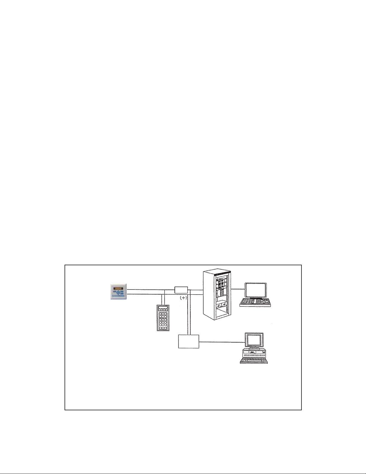
12.1 OVERVIEW OF HART COMMUNICATION
HART (highway addressable remote transducer) is a digital communication system in which two frequencies are
superimposed on the 4 to 20 mA output signal from the transmitter. A 1200 Hz sine wave represents the digit 1,
and a 2400 Hz sine wave represents the digit 0. Because the average value of a sine wave is zero, the digital signal adds no dc component to the analog signal. HART permits digital communication while retaining the analog
signal for process control.
The HART protocol, originally developed by Fisher-Rosemount, is now overseen by the independent HART
Communication Foundation. The Foundation ensures that all HART devices can communicate with one another.
For more information about HART communications, call the HART Communication Foundation at (512) 794-0369.
The internet address is http://www.hartcomm.org.
12.2 HART INTERFACE DEVICES
HART communicators allow the user to view measurement data (conductivity readings and temperature), program
the transmitter, and download information from the transmitter for transfer to a computer for analysis. Downloaded
information can also be sent to another HART transmitter. Either a hand-held communicator, such as the Rosemount
Model 275, or a computer can be used. HART interface devices operate from any wiring termination point in the
4 - 20 mA loop. A minimum load of 250 ohms must be present between the transmitter and the power supply. See
Figure 12-1.
If your communicator does not recognize the Model XMT-C transmitter, the device description library may need
updating. Call the manufacturer of your HART communication device for updates.
MODEL XMT-C SECTION 12.0
THEORY - REMOTE COMMUNICATIONS
SECTION 12.0
THEORY - REMOTE COMMUNICATIONS
4-20 mA + Digital
250
ohm
Control System
Computer
Model XMT
Smart
Transmitter
Bridge
Hand Held
Communicator
(“Configurator”)
FIGURE 12-1. HART Communicators.
Both the Rosemount Model 375 or 275 and a computer can be used to communicate
with a HART transmitter. The 250 ohm load (minimum) must be present between the
transmitter and the power supply.
65

66
MODEL XMT-C SECTION 12.0
THEORY - REMOTE COMMUNICATIONS
12.3 ASSET MANAGEMENT SOLUTIONS
Asset Management Solutions (AMS) is software that helps plant personnel better monitor the performance of analytical
instruments, pressure and temperature transmitters, and control valves. Continuous monitoring means maintenance personnel can anticipate equipment failures and plan preventative measures before costly breakdown maintenance is
required.
AMS uses remote monitoring. The operator, sitting at a computer, can view measurement data, change program settings,
read diagnostic and warning messages, and retrieve historical data from any HART-compatible device, including the Model
XMT-C transmitter. Although AMS allows access to the basic functions of any HART compatible device, Rosemount
Analytical has developed additional software for that allows access to all features of the Model XMT-C transmitter.
AMS can play a central role in plant quality assurance and quality control. Using AMS Audit Trail, plant operators can track
calibration frequency and results as well as warnings and diagnostic messages. The information is available to Audit Trail
whether calibrations were done using the infrared remote controller, the Model 375 or 275 HART communicator, or AMS
software.
AMS operates in Windows 95. See Figure 12-2 for a sample screen. AMS communicates through a HART-compatible
modem with any HART transmitters, including those from other manufacturers. AMS is also compatible with
FOUNDATION™ Fieldbus, which allows future upgrades to Fieldbus instruments.
For more information about AMS, including upgrades, renewals, and training, call Fisher-Rosemount Systems, Inc. at (612)
895-2000.
FIGURE 12-2. AMS Main Menu Tools

MODEL XMT-C SECTION 13.0
RETURN OF MATERIAL
SECTION 13.0
RETURN OF MATERIAL
13.1 GENERAL.
To expedite the repair and return of instruments, proper
communication between the customer and the factory
is important. Call 1-949-757-8500 for a Return
Materials Authorization (RMA) number.
13.2 WARRANTY REPAIR.
The following is the procedure for returning instruments still under warranty:
1. Call Rosemount Analytical for authorization.
2. To verify warranty, supply the factory sales order
number or the original purchase order number. In
the case of individual parts or sub-assemblies, the
serial number on the unit must be supplied.
3. Carefully package the materials and enclose your
“Letter of Transmittal” (see Warranty). If possible,
pack the materials in the same manner as they
were received.
4. Send the package prepaid to:
Emerson Process Management
Liquid Division
2400 Barranca Parkway
Irvine, CA 92606
Attn: Factory Repair
RMA No. ____________
Mark the package: Returned for Repair
Model No. ____
13.3 NON-WARRANTY REPAIR.
The following is the procedure for returning for repair
instruments that are no longer under warranty:
1. Call Rosemount Analytical for authorization.
2. Supply the purchase order number, and make
sure to provide the name and telephone number
of the individual to be contacted should additional
information be needed.
3. Do Steps 3 and 4 of Section 13.2.
NOTE
Consult the factory for additional information regarding service or repair.
67


WARRANTY
Goods and part(s) (excluding consumables) manufactured by Seller are warranted to be free from defects in workmanship and material under normal use and service for a period of twelve (12) months from the date of shipment by Seller.
Consumables, pH electrodes, membranes, liquid junctions, electrolyte, O-rings, etc. are warranted to be free from defects
in workmanship and material under normal use and service for a period of ninety (90) days from date of shipment by Seller.
Goods, part(s) and consumables proven by Seller to be defective in workmanship and / or material shall be replaced or
repaired, free of charge, F.O.B. Seller's factory provided that the goods, parts(s), or consumables are returned to Seller's
designated factory, transportation charges prepaid, within the twelve (12) month period of warranty in the case of goods
and part(s), and in the case of consumables, within the ninety (90) day period of warranty. This warranty shall be in effect
for replacement or repaired goods, part(s) and consumables for the remaining portion of the period of the twelve (12)
month warranty in the case of goods and part(s) and the remaining portion of the ninety (90) day warranty in the case of
consumables. A defect in goods, part(s) and consumables of the commercial unit shall not operate to condemn such commercial unit when such goods, parts(s) or consumables are capable of being renewed, repaired or replaced.
The Seller shall not be liable to the Buyer, or to any other person, for the loss or damage, directly or indirectly, arising
from the use of the equipment or goods, from breach of any warranty or from any other cause. All other warranties,
expressed or implied are hereby excluded.
IN CONSIDERATION OF THE STATED PURCHASE PRICE OF THE GOODS, SELLER GRANTS ONLY THE ABOVE
STATED EXPRESS WARRANTY. NO OTHER WARRANTIES ARE GRANTED INCLUDING, BUT NOT LIMITED TO,
EXPRESS AND IMPLIED WARRANTIES OF MERCHANTABILITY AND FITNESS FOR A PARTICULAR PURPOSE.
RETURN OF MATERIAL
Material returned for repair, whether in or out of warranty, should be shipped prepaid to:
Emerson Process Management
Liquid Division
2400 Barranca Parkway
Irvine, CA 92606
The shipping container should be marked:
Return for Repair
Model
_______________________________
The returned material should be accompanied by a letter of transmittal which should include the following information
(make a copy of the "Return of Materials Request" found on the last page of the Manual and provide the following thereon):
1. Location type of service, and length of time of service of the device.
2. Description of the faulty operation of the device and the circumstances of the failure.
3. Name and telephone number of the person to contact if there are questions about the returned material.
4. Statement as to whether warranty or non-warranty service is requested.
5. Complete shipping instructions for return of the material.
Adherence to these procedures will expedite handling of the returned material and will prevent unnecessary additional
charges for inspection and testing to determine the problem with the device.
If the material is returned for out-of-warranty repairs, a purchase order for repairs should be enclosed.

Credit Cards for U.S. Purchases Only.
The right people,
the right answers,
right now.
ON-LINE ORDERING NOW AVAILABLE ON OUR WEB SITE
http://www.raihome.com
Specifications subject to change without notice.
Emerson Process Management
2400 Barranca Parkway
Irvine, CA 92606 USA
Tel: (949) 757-8500
Fax: (949) 474-7250
http://www.raihome.com
© Rosemount Analytical Inc. 2011
8
 Loading...