

Page 1
Reference Manual
00809-0100-4045, Rev AB
Rosemount™ Wireless Pressure Gauge
with WirelessHART® Protocol
March 2016
Page 2

Page 3

Reference Manual
00809-0100-4045, Rev AB
Contents
1Section 1: Introduction
2Section 2: Hardware Installation
Table of Contents
March 2016
1.1 Using this manual. . . . . . . . . . . . . . . . . . . . . . . . . . . . . . . . . . . . . . . . . . . . . . . . . . . . . . 3
1.2 Models covered . . . . . . . . . . . . . . . . . . . . . . . . . . . . . . . . . . . . . . . . . . . . . . . . . . . . . . . 3
1.3 Product recycling/disposal . . . . . . . . . . . . . . . . . . . . . . . . . . . . . . . . . . . . . . . . . . . . . .3
2.1 Overview . . . . . . . . . . . . . . . . . . . . . . . . . . . . . . . . . . . . . . . . . . . . . . . . . . . . . . . . . . . . . 5
2.2 Safety messages. . . . . . . . . . . . . . . . . . . . . . . . . . . . . . . . . . . . . . . . . . . . . . . . . . . . . . . 5
2.3 Considerations . . . . . . . . . . . . . . . . . . . . . . . . . . . . . . . . . . . . . . . . . . . . . . . . . . . . . . . . 6
2.3.1 Pre-installation . . . . . . . . . . . . . . . . . . . . . . . . . . . . . . . . . . . . . . . . . . . . . . . . . . 6
2.3.2 Installation . . . . . . . . . . . . . . . . . . . . . . . . . . . . . . . . . . . . . . . . . . . . . . . . . . . . . . 7
2.3.3 Mechanical . . . . . . . . . . . . . . . . . . . . . . . . . . . . . . . . . . . . . . . . . . . . . . . . . . . . . . 7
2.3.4 Electrical . . . . . . . . . . . . . . . . . . . . . . . . . . . . . . . . . . . . . . . . . . . . . . . . . . . . . . . . 7
2.3.5 Environmental . . . . . . . . . . . . . . . . . . . . . . . . . . . . . . . . . . . . . . . . . . . . . . . . . . . 7
2.4 Installation procedure . . . . . . . . . . . . . . . . . . . . . . . . . . . . . . . . . . . . . . . . . . . . . . . . . .8
2.4.1 Seal and protect threads . . . . . . . . . . . . . . . . . . . . . . . . . . . . . . . . . . . . . . . . . . 8
2.4.2 Mount device. . . . . . . . . . . . . . . . . . . . . . . . . . . . . . . . . . . . . . . . . . . . . . . . . . . . 8
2.4.3 Turn on device. . . . . . . . . . . . . . . . . . . . . . . . . . . . . . . . . . . . . . . . . . . . . . . . . . . 9
2.5 Impulse piping considerations. . . . . . . . . . . . . . . . . . . . . . . . . . . . . . . . . . . . . . . . . . . 9
2.5.1 Best practices . . . . . . . . . . . . . . . . . . . . . . . . . . . . . . . . . . . . . . . . . . . . . . . . . . . 9
2.5.2 Mounting requirements . . . . . . . . . . . . . . . . . . . . . . . . . . . . . . . . . . . . . . . . .10
2.6 Process connection . . . . . . . . . . . . . . . . . . . . . . . . . . . . . . . . . . . . . . . . . . . . . . . . . . .11
2.7 Rosemount manifolds. . . . . . . . . . . . . . . . . . . . . . . . . . . . . . . . . . . . . . . . . . . . . . . . .11
2.7.1 Installation procedure . . . . . . . . . . . . . . . . . . . . . . . . . . . . . . . . . . . . . . . . . . .11
2.7.2 Manifold operation . . . . . . . . . . . . . . . . . . . . . . . . . . . . . . . . . . . . . . . . . . . . . .12
3Section 3: Configuration
3.1 Overview . . . . . . . . . . . . . . . . . . . . . . . . . . . . . . . . . . . . . . . . . . . . . . . . . . . . . . . . . . . .15
3.2 Safety messages. . . . . . . . . . . . . . . . . . . . . . . . . . . . . . . . . . . . . . . . . . . . . . . . . . . . . .15
3.3 System readiness . . . . . . . . . . . . . . . . . . . . . . . . . . . . . . . . . . . . . . . . . . . . . . . . . . . . .16
3.3.1 Confirm correct device driver . . . . . . . . . . . . . . . . . . . . . . . . . . . . . . . . . . . . .16
3.4 Configuration basics . . . . . . . . . . . . . . . . . . . . . . . . . . . . . . . . . . . . . . . . . . . . . . . . . .16
3.4.1 Configuration tools . . . . . . . . . . . . . . . . . . . . . . . . . . . . . . . . . . . . . . . . . . . . . 16
Table of Contents
3.4.2 Connection diagrams. . . . . . . . . . . . . . . . . . . . . . . . . . . . . . . . . . . . . . . . . . . . 17
3.5 Basic gauge setup . . . . . . . . . . . . . . . . . . . . . . . . . . . . . . . . . . . . . . . . . . . . . . . . . . . .17
3.5.1 Eliminate mounting effects. . . . . . . . . . . . . . . . . . . . . . . . . . . . . . . . . . . . . . . 17
i
Page 4

Table of Contents
March 2016
Reference Manual
00809-0100-4045, Rev AB
3.5.2 Activate wireless . . . . . . . . . . . . . . . . . . . . . . . . . . . . . . . . . . . . . . . . . . . . . . . .17
3.5.3 Considerations for devices with percent of range engineering unit . . . . 18
3.6 Configuration verification. . . . . . . . . . . . . . . . . . . . . . . . . . . . . . . . . . . . . . . . . . . . . .18
3.6.1 Review pressure information . . . . . . . . . . . . . . . . . . . . . . . . . . . . . . . . . . . . .18
3.6.2 Review device information . . . . . . . . . . . . . . . . . . . . . . . . . . . . . . . . . . . . . . . 19
3.6.3 Review radio information . . . . . . . . . . . . . . . . . . . . . . . . . . . . . . . . . . . . . . . . 19
3.6.4 Review operating parameters . . . . . . . . . . . . . . . . . . . . . . . . . . . . . . . . . . . .19
3.7 Advanced device parameter setup . . . . . . . . . . . . . . . . . . . . . . . . . . . . . . . . . . . . . .20
3.7.1 Write protect . . . . . . . . . . . . . . . . . . . . . . . . . . . . . . . . . . . . . . . . . . . . . . . . . . .20
3.7.2 Wireless update rate . . . . . . . . . . . . . . . . . . . . . . . . . . . . . . . . . . . . . . . . . . . .21
3.7.3 Dial update rate. . . . . . . . . . . . . . . . . . . . . . . . . . . . . . . . . . . . . . . . . . . . . . . . .21
3.8 Notifications and service. . . . . . . . . . . . . . . . . . . . . . . . . . . . . . . . . . . . . . . . . . . . . . .21
3.8.1 Simulating device variables. . . . . . . . . . . . . . . . . . . . . . . . . . . . . . . . . . . . . . . 21
3.8.2 Device reset . . . . . . . . . . . . . . . . . . . . . . . . . . . . . . . . . . . . . . . . . . . . . . . . . . . . 22
3.8.3 Join status . . . . . . . . . . . . . . . . . . . . . . . . . . . . . . . . . . . . . . . . . . . . . . . . . . . . . .22
3.9 Advanced configuration . . . . . . . . . . . . . . . . . . . . . . . . . . . . . . . . . . . . . . . . . . . . . . .22
3.9.1 Overpressure notification . . . . . . . . . . . . . . . . . . . . . . . . . . . . . . . . . . . . . . . . 22
3.9.2 Acknowledge and reset overpressure notification . . . . . . . . . . . . . . . . . . . 25
4Section 4: Operation and Maintenance
4.1 Overview . . . . . . . . . . . . . . . . . . . . . . . . . . . . . . . . . . . . . . . . . . . . . . . . . . . . . . . . . . . .27
4.2 Safety messages. . . . . . . . . . . . . . . . . . . . . . . . . . . . . . . . . . . . . . . . . . . . . . . . . . . . . .27
4.3 Pressure signal trimming . . . . . . . . . . . . . . . . . . . . . . . . . . . . . . . . . . . . . . . . . . . . . .27
4.3.1 Determining necessary sensor trims. . . . . . . . . . . . . . . . . . . . . . . . . . . . . . .28
4.3.2 Sensor trim overview . . . . . . . . . . . . . . . . . . . . . . . . . . . . . . . . . . . . . . . . . . . . 28
4.3.3 Sensor trim. . . . . . . . . . . . . . . . . . . . . . . . . . . . . . . . . . . . . . . . . . . . . . . . . . . . . 30
4.3.4 Dial adjustment. . . . . . . . . . . . . . . . . . . . . . . . . . . . . . . . . . . . . . . . . . . . . . . . . 31
4.3.5 Recall factory trim—sensor trim . . . . . . . . . . . . . . . . . . . . . . . . . . . . . . . . . . .31
4.4 Replacing the battery . . . . . . . . . . . . . . . . . . . . . . . . . . . . . . . . . . . . . . . . . . . . . . . . .32
4.5 Local device status and notifications . . . . . . . . . . . . . . . . . . . . . . . . . . . . . . . . . . . .33
5Section 5: Troubleshooting
5.1 Service support. . . . . . . . . . . . . . . . . . . . . . . . . . . . . . . . . . . . . . . . . . . . . . . . . . . . . . .35
5.2 Local troubleshooting . . . . . . . . . . . . . . . . . . . . . . . . . . . . . . . . . . . . . . . . . . . . . . . . .36
5.3 Remote troubleshooting . . . . . . . . . . . . . . . . . . . . . . . . . . . . . . . . . . . . . . . . . . . . . .37
ii
Table of Contents
Page 5

Reference Manual
00809-0100-4045, Rev AB
AAppendix A: Specifications and Reference Data
Table of Contents
March 2016
A.1 Physical specifications. . . . . . . . . . . . . . . . . . . . . . . . . . . . . . . . . . . . . . . . . . . . . . . . .41
A.1.1 Material selection . . . . . . . . . . . . . . . . . . . . . . . . . . . . . . . . . . . . . . . . . . . . . . . 41
A.1.2 Dial size. . . . . . . . . . . . . . . . . . . . . . . . . . . . . . . . . . . . . . . . . . . . . . . . . . . . . . . . 41
A.1.3 Scale ranges . . . . . . . . . . . . . . . . . . . . . . . . . . . . . . . . . . . . . . . . . . . . . . . . . . . .41
A.1.4 Process connections. . . . . . . . . . . . . . . . . . . . . . . . . . . . . . . . . . . . . . . . . . . . .41
A.1.5 Field Communicator connections . . . . . . . . . . . . . . . . . . . . . . . . . . . . . . . . . 41
A.1.6 Material of construction . . . . . . . . . . . . . . . . . . . . . . . . . . . . . . . . . . . . . . . . . 41
A.1.7 Shipping weight . . . . . . . . . . . . . . . . . . . . . . . . . . . . . . . . . . . . . . . . . . . . . . . .41
A.2 Operating specifications. . . . . . . . . . . . . . . . . . . . . . . . . . . . . . . . . . . . . . . . . . . . . . .42
A.2.1 Conformance to specification (±3 [Sigma]). . . . . . . . . . . . . . . . . . . . . . . . . 42
A.2.2 Accuracy . . . . . . . . . . . . . . . . . . . . . . . . . . . . . . . . . . . . . . . . . . . . . . . . . . . . . . .42
A.2.3 Temperature limits. . . . . . . . . . . . . . . . . . . . . . . . . . . . . . . . . . . . . . . . . . . . . . 42
A.2.4 Electrical connections/battery . . . . . . . . . . . . . . . . . . . . . . . . . . . . . . . . . . . . 42
A.2.5 Overpressure limit . . . . . . . . . . . . . . . . . . . . . . . . . . . . . . . . . . . . . . . . . . . . . . 42
A.2.6 Burst pressure limit. . . . . . . . . . . . . . . . . . . . . . . . . . . . . . . . . . . . . . . . . . . . . . 42
A.2.7 Minimum span limits for percent of range engineering unit . . . . . . . . . . 42
A.2.8 Ambient temperature effect per 18 °F (10 °C). . . . . . . . . . . . . . . . . . . . . . . 42
A.2.9 Digital zero trim . . . . . . . . . . . . . . . . . . . . . . . . . . . . . . . . . . . . . . . . . . . . . . . . 42
A.2.10Humidity limits. . . . . . . . . . . . . . . . . . . . . . . . . . . . . . . . . . . . . . . . . . . . . . . . .42
A.2.11Electromagnetic compatibility (EMC) . . . . . . . . . . . . . . . . . . . . . . . . . . . . .42
A.2.12Status indication. . . . . . . . . . . . . . . . . . . . . . . . . . . . . . . . . . . . . . . . . . . . . . . .42
A.2.13Output . . . . . . . . . . . . . . . . . . . . . . . . . . . . . . . . . . . . . . . . . . . . . . . . . . . . . . . . 43
A.2.14Wireless radio (internal antenna) . . . . . . . . . . . . . . . . . . . . . . . . . . . . . . . . . 43
A.2.15Wireless update rate . . . . . . . . . . . . . . . . . . . . . . . . . . . . . . . . . . . . . . . . . . . . 43
A.2.16Vibration effect. . . . . . . . . . . . . . . . . . . . . . . . . . . . . . . . . . . . . . . . . . . . . . . . .43
A.2.17Dial update rate . . . . . . . . . . . . . . . . . . . . . . . . . . . . . . . . . . . . . . . . . . . . . . . . 43
A.3 Wireless connectivity out-of-the-box . . . . . . . . . . . . . . . . . . . . . . . . . . . . . . . . . . . .43
A.4 Spare parts. . . . . . . . . . . . . . . . . . . . . . . . . . . . . . . . . . . . . . . . . . . . . . . . . . . . . . . . . . .43
A.5 Pressure scale ranges. . . . . . . . . . . . . . . . . . . . . . . . . . . . . . . . . . . . . . . . . . . . . . . . . .48
BAppendix B: Product Certifications
B.1 European Union Directive Information . . . . . . . . . . . . . . . . . . . . . . . . . . . . . . . . . .51
B.2 Telecommunication compliance. . . . . . . . . . . . . . . . . . . . . . . . . . . . . . . . . . . . . . . .51
B.3 FCC and IC . . . . . . . . . . . . . . . . . . . . . . . . . . . . . . . . . . . . . . . . . . . . . . . . . . . . . . . . . . .51
B.4 Ordinary location certification from CSA. . . . . . . . . . . . . . . . . . . . . . . . . . . . . . . . .51
Table of Contents
B.5 Installing in North America. . . . . . . . . . . . . . . . . . . . . . . . . . . . . . . . . . . . . . . . . . . . .51
B.5.1 USA . . . . . . . . . . . . . . . . . . . . . . . . . . . . . . . . . . . . . . . . . . . . . . . . . . . . . . . . . . .52
iii
Page 6

Table of Contents
March 2016
CAppendix C: Field Communicator Menu Trees
DAppendix D: Network Design Best Practices
EAppendix E: Device Variable Index
Reference Manual
00809-0100-4045, Rev AB
B.5.2 Canada . . . . . . . . . . . . . . . . . . . . . . . . . . . . . . . . . . . . . . . . . . . . . . . . . . . . . . . .52
B.5.3 Europe. . . . . . . . . . . . . . . . . . . . . . . . . . . . . . . . . . . . . . . . . . . . . . . . . . . . . . . . . 52
B.5.4 International . . . . . . . . . . . . . . . . . . . . . . . . . . . . . . . . . . . . . . . . . . . . . . . . . . . 52
C.1 Overview . . . . . . . . . . . . . . . . . . . . . . . . . . . . . . . . . . . . . . . . . . . . . . . . . . . . . . . . . . . .55
D.1 Overview . . . . . . . . . . . . . . . . . . . . . . . . . . . . . . . . . . . . . . . . . . . . . . . . . . . . . . . . . . . .59
D.2 Effective range . . . . . . . . . . . . . . . . . . . . . . . . . . . . . . . . . . . . . . . . . . . . . . . . . . . . . . .59
E.1 Messages and descriptions. . . . . . . . . . . . . . . . . . . . . . . . . . . . . . . . . . . . . . . . . . . . .61
iv
Table of Contents
Page 7

Reference Manual
NOTICE
00809-0100-4045, Rev AB
Rosemount™ Wireless Pressure
Gauge
The products described in this document are NOT designed for nuclear-qualified
applications. Using non-nuclear qualified products in applications that require
nuclear-qualified hardware or products may cause inaccurate readings.
For information on Emerson
contact your local Rosemount Sales Representative.
This device complies with Part 15 of the FCC Rules. Operation is subject to the
following conditions: This device may not cause harmful interference. This device must
accept any interference received, including interference that may cause undesired
operation.
Changes or modification not expressly approved by Rosemount Inc. could void the
user’s authority to operate the equipment.
Using the Rosemount Wireless Pressure Gauge in a manner other than what is specified
by the manufacturer may impair the protection provided by the equipment.
This device must be installed to ensure a minimum antenna separation distance of
20 cm (8 in.) from all persons.
Shipping considerations
The unit is shipped with the battery installed.
Each device contains one “D” size primary lithium-thionyl chloride battery. Primary 5.0
gram lithium batteries are regulated in transportation by the U.S. Department of
Transportation, and are also covered by IATA (International Air Transport Association),
ICAO (International Civil Aviation Organization), and ARD (European Ground
Transportation of Dangerous Goods). It is the responsibility of the shipper to ensure
compliance with these or any other local requirements. Consult current regulations
and requirements before shipping.
™
Process Management nuclear-qualified products,
Title Page
March 2016
Title Page
1
Page 8
Title Page
March 2016
Reference Manual
00809-0100-4045, Rev AB
Explosions could result in death or serious injury.
Installation of device in an explosive environment must be in accordance with
appropriate local, national and international standards, codes, and practices.
Ensure device is installed in accordance with intrinsically safe or non-incendive
field practices.
Before connecting a Field Communicator in an explosive atmosphere, make sure
the instruments are installed in accordance with intrinsically safe or
non-incendive field wiring practices.
Verify the operating atmosphere of the device is consistent with the appropriate
hazardous locations certifications.
Electrical shock can result in death or serious injury.
Care must be taken during transportation of device to prevent electrostatic
charge build-up.
Device must be installed to ensure a minimum antenna separation distance of
8 in. (20 cm) from all persons.
Process leaks could result in death or serious injury.
Handle the device carefully.
Failure to follow safe installation guidelines could result in death or serious injury.
Only qualified personnel should install the equipment.
Apply wrench only to the flats, not on housing.
The battery is not replaceable in a hazardous location.
Keep the vent path free of any obstruction, including but not limited to paint, dust, and
lubrication by mounting the device so the process can drain away.
Interfering or blocking the atmospheric reference port will cause the device to output
erroneous pressure values.
Keep the vent path free of any obstruction, including but not limited to paint, dust, and
lubrication by mounting the device so the process can drain away.
Absolute pressure devices are calibrated at the factory. Trimming adjusts the position of
the factory characterization curve. It is possible to degrade performance of the device if
any trim is done improperly or with inaccurate equipment.
Individuals who handle products exposed to a hazardous substance can avoid injury if
they are informed of and understand the hazard. The product being returned will require
a copy of the required Material Safety Data Sheet (MSDS) for each substance must be
included with the returned goods.
2
Title Page
Page 9

Reference Manual
00809-0100-4045, Rev AB
Section 1 Introduction
1.1 Using this manual
The sections in this manual provide information on installing, operating, and maintaining
the Rosemount
organized as follows:
Section 2: Hardware Installation contains mechanical and electrical installation instructions
and considerations.
Section 3: Configuration provides instruction on commissioning and operating the gauge.
Information on software functions, configuration parameters, and online variables are also
included.
Section 4: Operation and Maintenance contains operation and maintenance techniques.
Section 5: Troubleshooting provides troubleshooting techniques for the most common
operating problems.
™
Wireless Pressure Gauge with WirelessHART® protocol. The sections are
Introduction
March 2016
Appendix A: Specifications and Reference Data supplies reference and specification data, as
well as ordering information.
Appendix B: Product Certifications contains approval information.
Appendix C: Field Communicator Menu Trees provides full menu trees and abbreviated fast
key sequences for commissioning tasks.
Appendix D: Network Design Best Practices provides information on how to optimize
network reliability and performance.
1.2 Models covered
This manual covers the Rosemount Wireless Pressure Gauge.
Measures gage/absolute/compound/vacuum pressure up to 4000 psi (275 bar)
1.3 Product recycling/disposal
Recycling of equipment and packaging should be taken into consideration and disposed of
in accordance with local and national legislation/regulations.
Introduction
3
Page 10

Introduction
March 2016
Reference Manual
00809-0100-4045, Rev AB
4
Introduction
Page 11

Reference Manual
00809-0100-4045, Rev AB
Hardware Installation
Section 2 Hardware Installation
Overview . . . . . . . . . . . . . . . . . . . . . . . . . . . . . . . . . . . . . . . . . . . . . . . . . . . . . . . . . . . . . . . . page 5
Safety messages . . . . . . . . . . . . . . . . . . . . . . . . . . . . . . . . . . . . . . . . . . . . . . . . . . . . . . . . . . page 5
Considerations . . . . . . . . . . . . . . . . . . . . . . . . . . . . . . . . . . . . . . . . . . . . . . . . . . . . . . . . . . . page 6
Installation procedure . . . . . . . . . . . . . . . . . . . . . . . . . . . . . . . . . . . . . . . . . . . . . . . . . . . . . page 8
Impulse piping considerations . . . . . . . . . . . . . . . . . . . . . . . . . . . . . . . . . . . . . . . . . . . . . . page 9
Process connection . . . . . . . . . . . . . . . . . . . . . . . . . . . . . . . . . . . . . . . . . . . . . . . . . . . . . . . page 11
Rosemount manifolds . . . . . . . . . . . . . . . . . . . . . . . . . . . . . . . . . . . . . . . . . . . . . . . . . . . . . page 11
2.1 Overview
The information in this section covers installation considerations. A Quick Start Guide
(document number 00825-0100-4045) is shipped with every device to describe basic
installation and startup procedures. Dimensional drawings for the Rosemount
Pressure Gauge can be found in Appendix A: Specifications and Reference Data.
March 2016
™
Wireless
2.2 Safety messages
Procedures and instructions in this section may require special precautions to ensure the
safety of the personnel performing the operation. Information that raises potential safety
issues is indicated with a warning symbol ( ). Refer to the following safety messages
before performing an operation preceded by this symbol.
Explosions could result in death or serious injury.
Installation of device in an explosive environment must be in accordance with
appropriate local, national and international standards, codes, and practices.
Ensure device is installed in accordance with intrinsically safe or non-incendive field
practices.
Electrical shock can result in death or serious injury.
Care must be taken during transportation of device to prevent electrostatic charge
build-up.
Device must be installed to ensure a minimum antenna separation distance of 8 in.
(20 cm) from all persons.
Process leaks could result in death or serious injury.
Handle the device carefully.
Failure to follow safe installation guidelines could result in death or serious injury.
Only qualified personnel should install the equipment.
Hardware Installation
5
Page 12
Hardware Installation
March 2016
2.3 Considerations
2.3.1 Pre-installation
Optional: power/device check
The device is designed to be installation-ready. To check device battery prior to installation,
perform the following:
1. Perform “Turn on device” on page 9.
2. Slide the ON/OFF switch to the OFF position until ready for use.
Network design best practices
When mounting the device, recommended practices should be considered to achieve the
best wireless performance. See Appendix D: Network Design Best Practices for more
information on recommend practices.
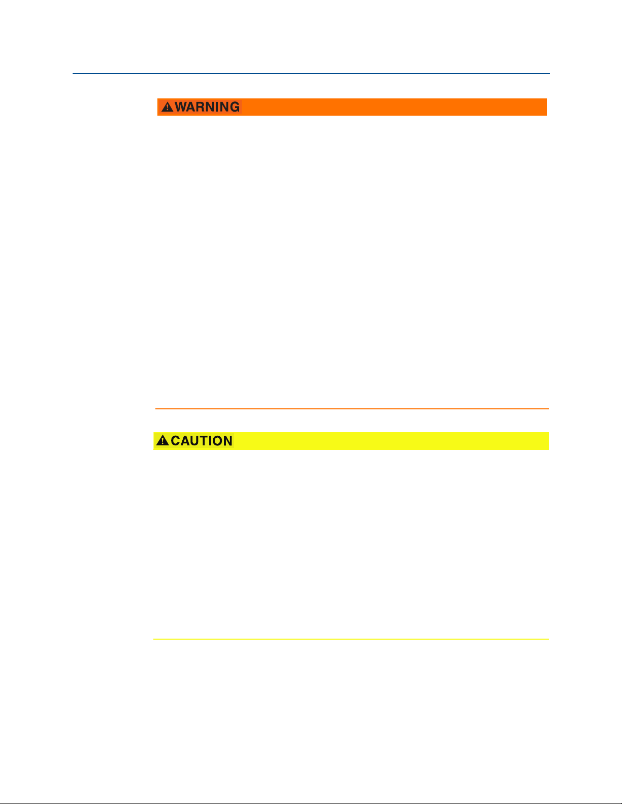
Field Communicator connections
Reference Manual
00809-0100-4045, Rev AB
The device needs to be on in order for the Field Communicator to interface with the
Rosemount Wireless Pressure Gauge. The Field Communicator connection is located to the
right of the ON/OFF switch. To communicate with the device, connect the Field
Communicator to connections labeled “COMM”. Field communication with this device
requires a HART-based tool using the correct Rosemount Wireless Pressure Gauge device
driver (DD). Refer to Figure 2-1 for instructions on connecting the Field Communicator to
the device.
Figure 2-1. Connect to Device
A
123
645
8709
B
A. Field Communicator
B. HART modem
C. AMS Wireless Configurator
C
6
Hardware Installation
Page 13

Reference Manual
00809-0100-4045, Rev AB
2.3.2 Installation
Measurement performance depends upon proper installation of the device and impulse
piping. Mount the device close to the process and use a minimum of piping to achieve best
performance. Also, consider the need for easy access, personnel safety, and a suitable
device environment. Install the device to minimize vibration, shock, and temperature
fluctuation.
2.3.3 Mechanical
Location
When choosing an installation location and position, take into account the direction of the
device for future access to the COMM connections and readability of the analog display.
Electronics cover
The electronics cover is tightened so that polymer contacts polymer. When removing the
electronics cover, ensure that there is no damage done to the o-ring. If damaged replace
before reattaching cover, ensuring polymer contacts polymer (i.e. no O-ring visible).
Hardware Installation
March 2016
2.3.4 Electrical
Battery
The Rosemount Wireless Pressure Gauge is self-powered. The battery contains
approximately five grams of lithium. Under normal conditions, the battery materials are
self-contained and are not reactive as the as the battery is maintained inside the enclosure
of the device. Care should be taken to prevent thermal, electrical, or mechanical damage.
Contacts should be protected to prevent premature discharge.
Use caution when handling the battery, it may be damaged if dropped.
The battery should be stored in a clean dry area, For maximum battery life, storage
temperature should not exceed 86 °F (30 °C).
2.3.5 Environmental
Verify the operating atmosphere of the device is consistent with the appropriate hazardous
locations certifications.
Temperature effects
The device will operate within specifications for ambient temperatures as outlined on
page 42 in the specifications section. Heat from the process is transferred to the device
housing. If the process temperature is high, the ambient temperature will need to be lower
to account for heat transferred to the device housing. See Temperature limits for process
temperature derating.
Hardware Installation
7
Page 14
Hardware Installation
OR
March 2016
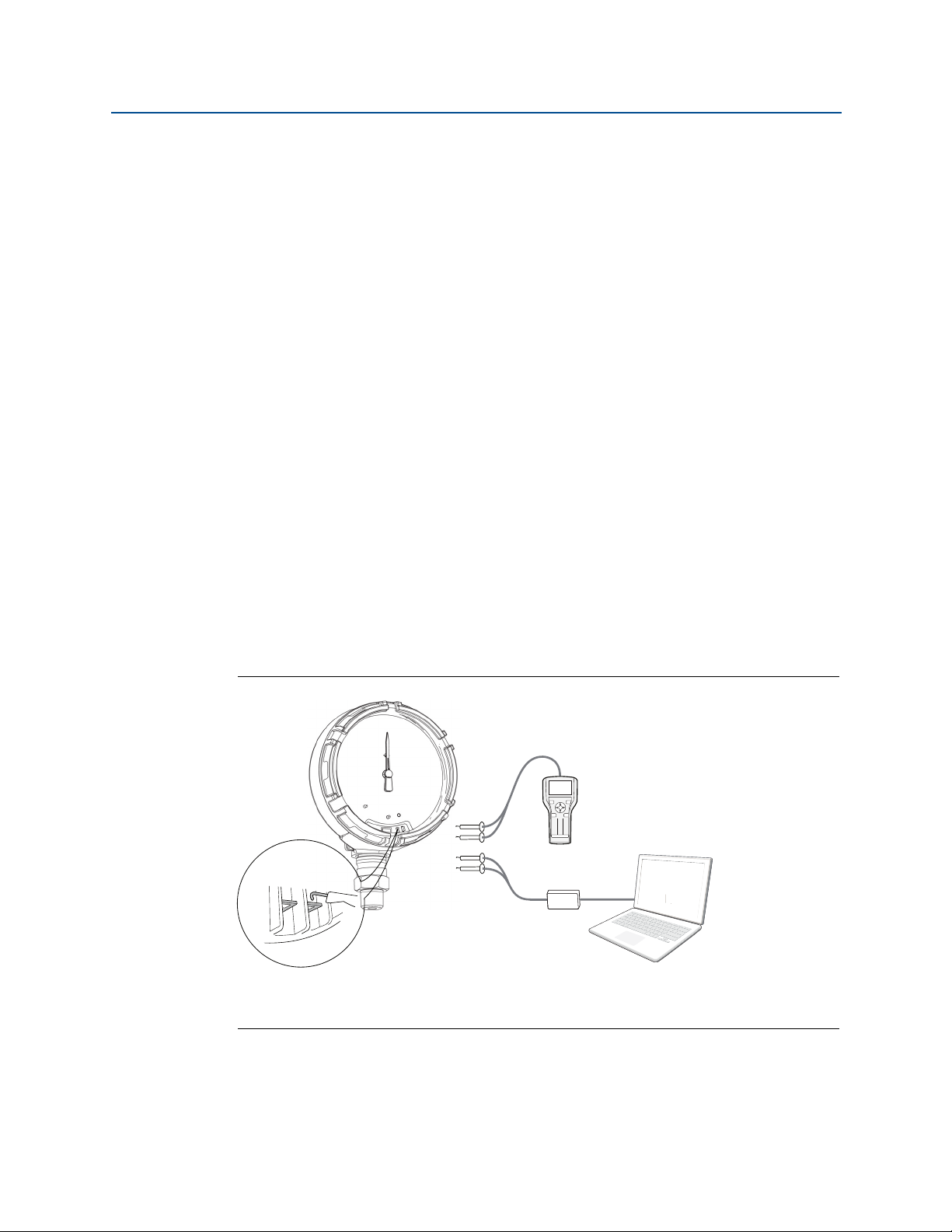
2.4 Installation procedure
Figure 2-2. Installation Flowchart
2.4.1 Seal and protect threads
Reference Manual
00809-0100-4045, Rev AB
2.4.2 Mount device
Note
Use wrench on flats, not on housing.
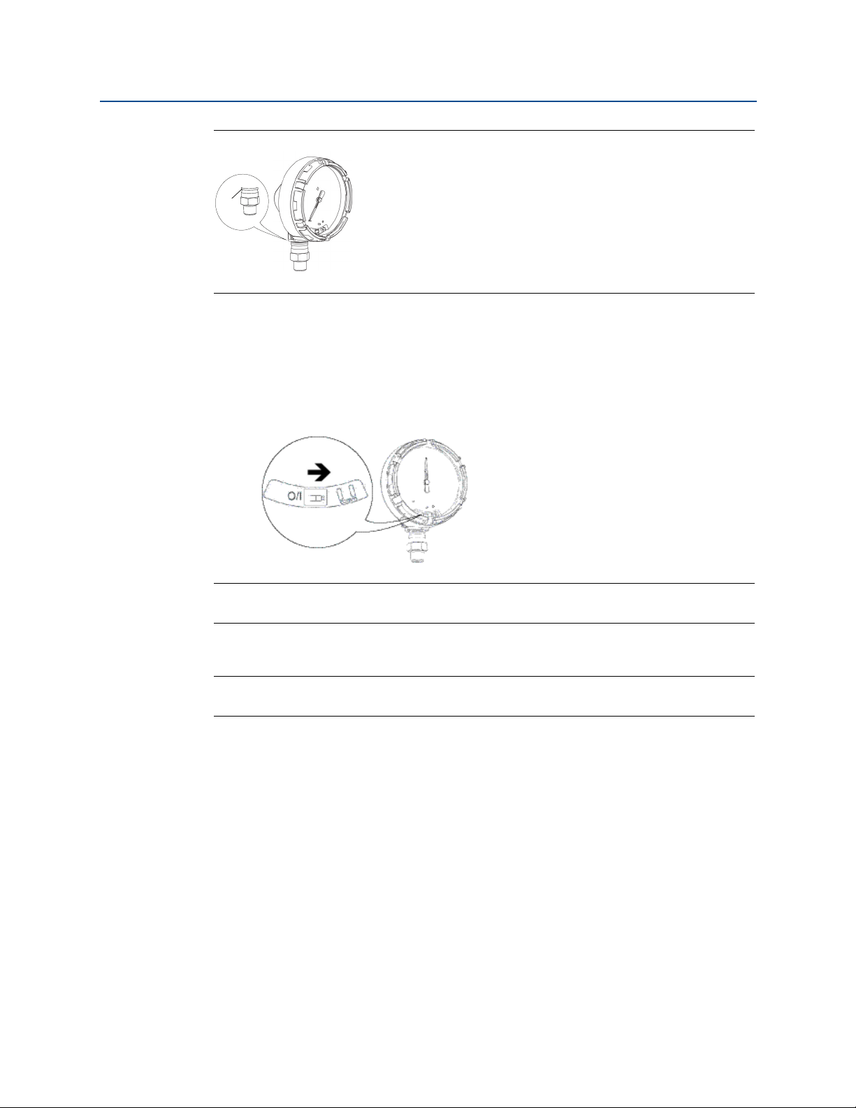
Mounting orientation
The low side pressure port (atmospheric reference) on the process pressure gauge is
located in the neck of the device behind the housing. The vent path is between the housing
and sensor. (See Figure 2-3.)
Keep the vent path free of any obstruction, including but not limited to paint, dust, and
lubrication by mounting the device so the process can drain away.
8
Hardware Installation
Page 15
Reference Manual
A
00809-0100-4045, Rev AB
Figure 2-3. Low Side Pressure Port
A. Low side pressure port (atmospheric reference)
2.4.3 Turn on device
Check to ensure the device and battery are working properly.
1. Twist the cover counterclockwise to remove it.
2. Slide the OFF/ON switch to the ON position to initiate the power sequence.
Hardware Installation
March 2016
Note
During the power sequence, the dial tests full range of motion and LED flashes amber.
3. Once the power sequence ends, verify the LED flashes green.
Note
The LED may display several colors; see Table 4-2 on page 33 for device statuses.
2.5 Impulse piping considerations
2.5.1 Best practices
The piping between the process and the device must accurately transfer the pressure to
obtain accurate measurements. There are five possible sources of error: leaks, friction loss
(particularly if purging is used), trapped gas in a liquid line, liquid in a gas line, and density
variations between the legs.
Hardware Installation
9
Page 16

Hardware Installation
March 2016
The best location for the device in relation to the process pipe depends on the process itself.
Use the following guidelines to determine device location and placement of impulse piping:
Keep impulse piping as short as possible.
For liquid service, slope the impulse piping at least 1 inch per foot (8 cm per m)
For gas service, slope the impulse piping at least 1 inch per foot (8 cm per m)
Avoid high points in liquid lines and low points in gas lines.
Make sure both impulse legs are the same temperature.
Use impulse piping large enough to avoid friction effects and blockage.
Vent all gas from liquid piping legs.
When using a sealing fluid, fill both piping legs to the same level.
When purging, make the purge connection close to the process taps and purge
Keep corrosive or hot (above 250 °F [121 °C]) process material out of direct contact
Prevent sediment deposits in the impulse piping.
Reference Manual
00809-0100-4045, Rev AB
upward from the device toward the process connection.
downward from the device toward the process connection.
through equal lengths of the same size pipe. Avoid purging through the device.
with the sensor module and flanges.
Keep the liquid head balanced on both legs of the impulse piping.
Avoid conditions that might allow process fluid to freeze within the process flange.
2.5.2 Mounting requirements
Liquid flow measurement
Place taps to the side of the line to prevent sediment deposits on the process
isolators.
Mount the device beside or below the taps so gases vent into the process line.
Mount drain/vent valve upward to allow gases to vent.
Gas flow measurement
Place taps in the top or side of the line.
Mount the device beside or above the taps so to drain liquid into the process line.
Steam flow measurement
Place taps to the side of the line.
Mount the device below the taps to ensure that impulse piping will remain filled
with condensate.
Fill impulse lines with water to prevent steam from contacting the device directly
and to ensure accurate measurement start-up.
10
Note
For steam or other elevated temperature services, it is important that temperatures do not
exceed 250 °F (121 °C) for devices with silicone fill. For vacuum service, these temperature
limits are reduced to 220 °F (104 °C) for silicone fill.
Hardware Installation
Page 17
Reference Manual
A
00809-0100-4045, Rev AB
2.6 Process connection
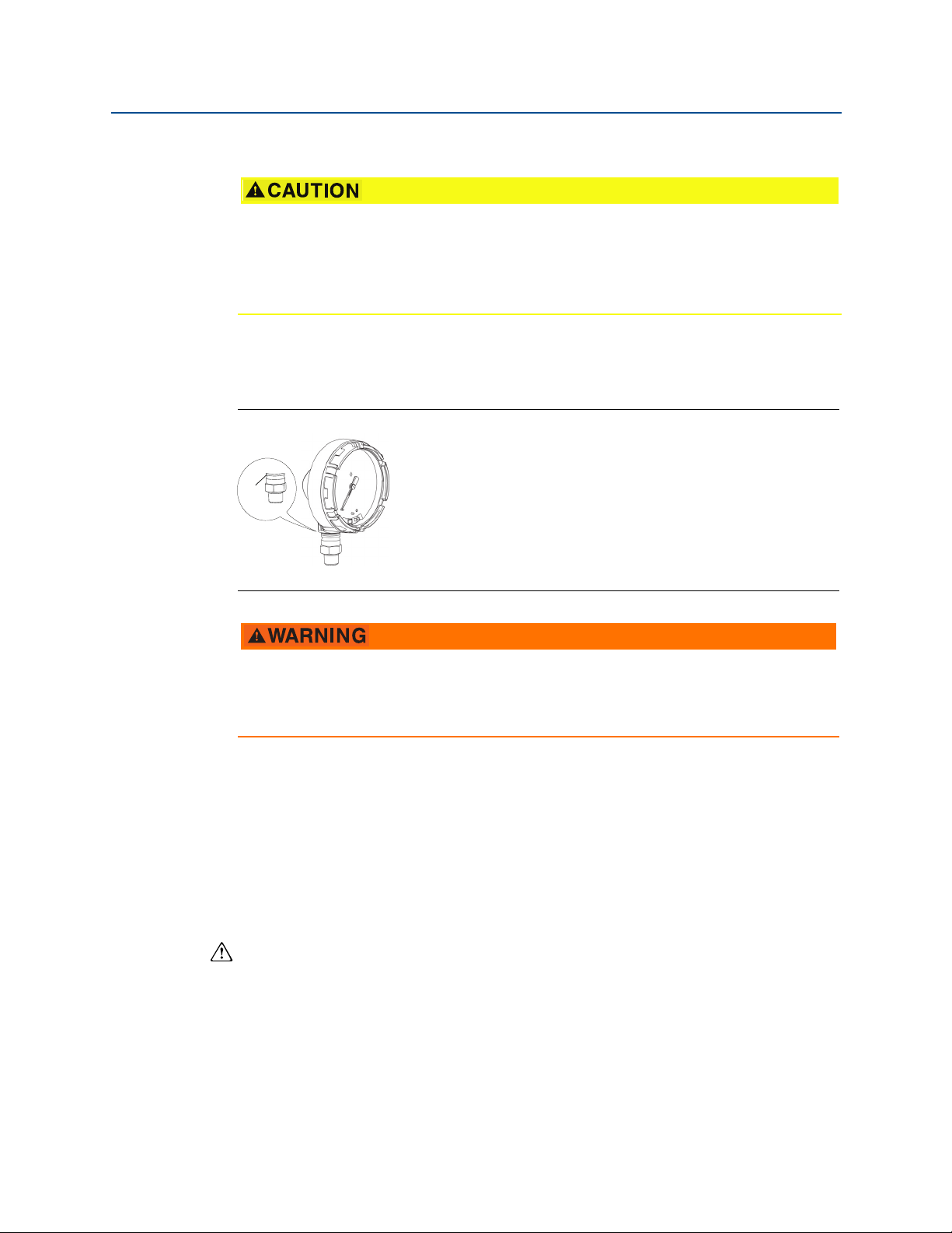
Interfering or blocking the atmospheric reference port will cause the device to output
erroneous pressure values.
Keep the vent path free of any obstruction, including but not limited to paint, dust, and
lubrication by mounting the device so the process can drain away.
The low side pressure port (atmospheric reference) on the process pressure gauge is
located in the neck of the device behind the housing. The vent path is between the housing
and sensor. (See Figure 2-3.)
Figure 2-4. Low Side Pressure Port
Hardware Installation
March 2016
A. Low side pressure port (atmospheric reference)
a
Do not apply torque directly to the sensor module. Rotation between the sensor
module and the process connection can damage the electronics. To avoid damage,
apply torque only to the hex-shaped process connection.
2.7 Rosemount manifolds
The Rosemount 306 Integral Manifold mounts directly to the device. The manifold is used
with this device to provide block-and-bleed valve capabilities of up to 4000 psi (275 bar).
2.7.1 Installation procedure
The Rosemount 306 Manifold is for use only with a Rosemount Wireless Pressure Gauge.
Assemble the Rosemount 306 Manifold to the device with a thread sealant.
1. Place device into holding fixture.
2. Apply appropriate thread paste or tape to threaded instrument end of the
manifold.
3. Count total threads on the manifold before starting assembly.
4. Start turning the manifold by hand into the process connection on the device.
Hardware Installation
11
Page 18
Hardware Installation
Device
Test/vent
(closed)
Isolate
Process
(open)
March 2016
Note
If using thread tape, be sure the thread tape does not strip when the manifold assembly is
started.
5. Wrench tighten manifold into process connection (minimum toque value is
425 in-lbs).
6. Count how many threads are still showing (minimum engagement is 3
revolutions).
7. Subtract the number of threads showing (after tightening) from the total threads
to calculate the revolutions engaged. Further tighten until a minimum of 3
rotations is achieved.
8. For block and bleed manifold, verify the bleed screw is installed and tightened. For
2-valve manifold, verify the vent plug is installed and tightened.
9. Leak-check assembly to maximum pressure range of device.
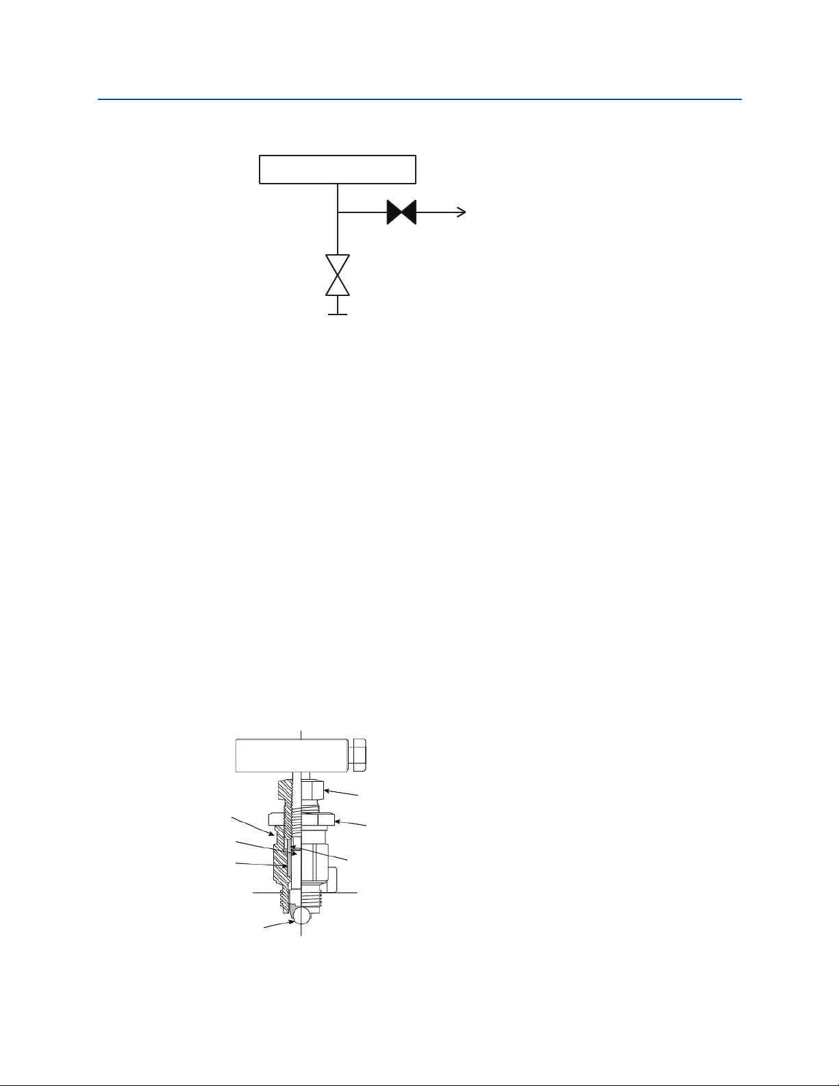
2.7.2 Manifold operation
Reference Manual
00809-0100-4045, Rev AB
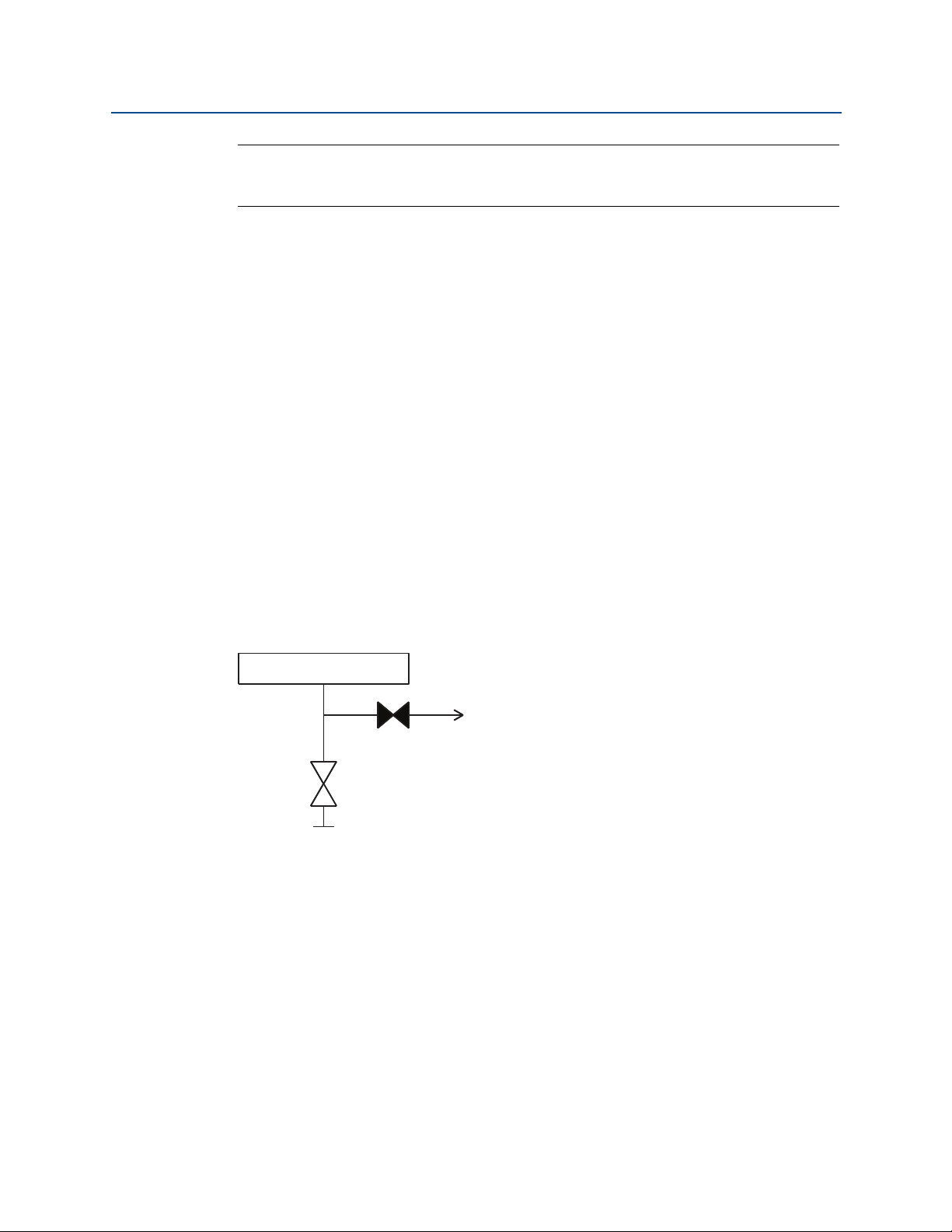
2-Valve and Block and Bleed Style Manifolds
Isolating the device
In normal operation the Isolate (block) valve between the process port and device will be
open and the Test/Vent valve will be closed. On a block and bleed style manifold, a single
block valve provides device isolation and a bleed screw provides drain/vent capabilities.
12
Hardware Installation
Page 19
Reference Manual
Device
Test/vent
(closed)
Isolate
Process
(closed)
Device
Test/vent
(open)
Isolate
Process
(closed)
Device
Test/vent
(closed)
Isolate
Process
(closed)
00809-0100-4045, Rev AB
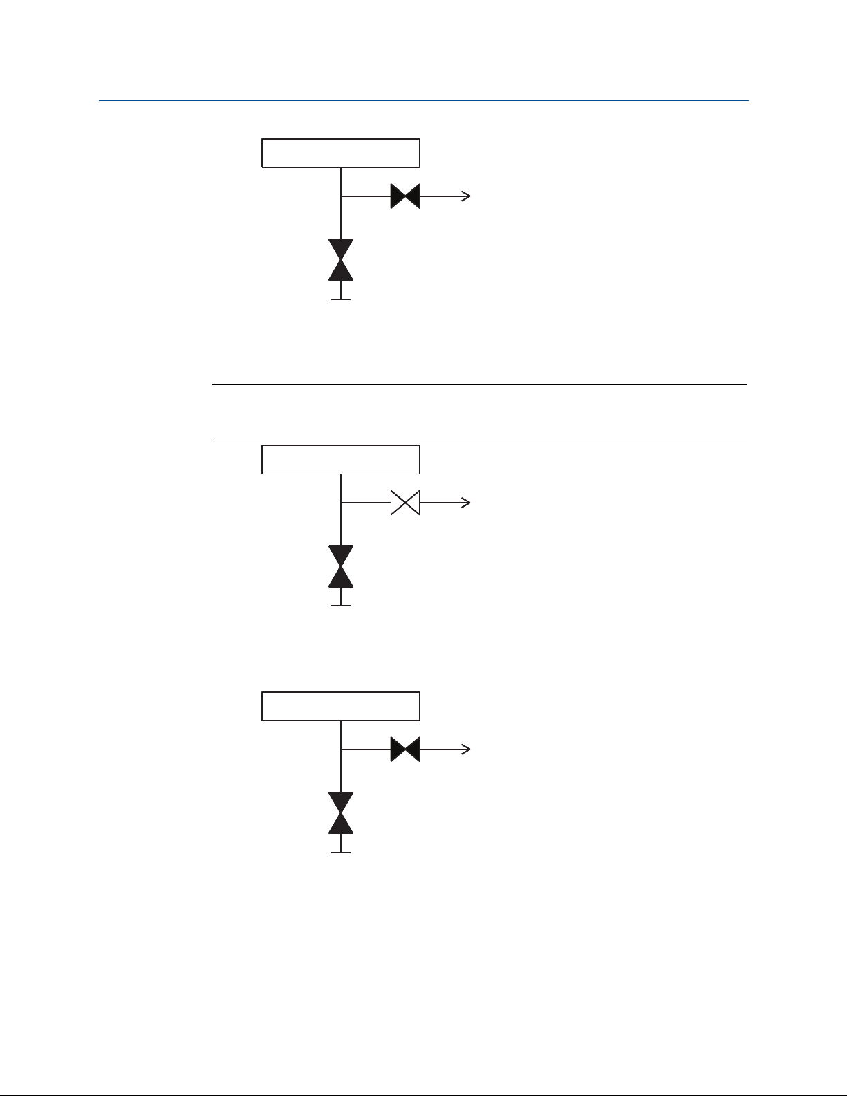
1. To isolate the device, close the isolate valve.
2. To bring the device to atmospheric pressure, open the vent valve or bleed screw.
Note:
1
A
/4-in. male NPT pipe plug may be installed in the test/vent port and will need to be
removed with a wrench in order to vent the manifold properly.
Hardware Installation
March 2016
Hardware Installation
3. After venting to atmosphere, perform any required calibration and then close the
test/vent valve or replace the bleed screw.
13
Page 20
Hardware Installation
Device
Test/vent
(closed)
Isolate
Process
(open)
A
B
C
D
E
F
G
March 2016
4. Open the Isolate (block) valve to return the device to service.
Adjusting valve packing
Over time, the packing material inside a Rosemount manifold may require adjustment in
order to continue to provide proper pressure retention. Not all Rosemount manifolds have
this adjustment capability. The Rosemount manifold model number will indicate what type
of stem seal or packing material has been used.
Reference Manual
00809-0100-4045, Rev AB
The following steps are provided as a procedure to adjust valve packing.
1. Remove all pressure from device.
2. Loosen manifold valve jam nut.
3. Tighten manifold valve packing adjuster nut
1
/4 turn.
4. Tighten manifold valve jam nut.
5. Re-apply pressure and check for leaks.
6. Above steps can be repeated, if necessary.
If the above procedure does not result in proper pressure retention, the complete manifold
should be replaced.
14
A. Bonnet
B. Stem
C. Packing
D. Ball seat
E. Packing adjuster
F. J am nut
G. Packing follower
Hardware Installation
Page 21

Reference Manual
00809-0100-4045, Rev AB
Section 3 Configuration
Overview . . . . . . . . . . . . . . . . . . . . . . . . . . . . . . . . . . . . . . . . . . . . . . . . . . . . . . . . . . . . . . . . page 15
Safety messages . . . . . . . . . . . . . . . . . . . . . . . . . . . . . . . . . . . . . . . . . . . . . . . . . . . . . . . . . . page 15
System readiness . . . . . . . . . . . . . . . . . . . . . . . . . . . . . . . . . . . . . . . . . . . . . . . . . . . . . . . . . page 16
Configuration basics . . . . . . . . . . . . . . . . . . . . . . . . . . . . . . . . . . . . . . . . . . . . . . . . . . . . . . page 16
Basic gauge setup . . . . . . . . . . . . . . . . . . . . . . . . . . . . . . . . . . . . . . . . . . . . . . . . . . . . . . . . . page 17
Configuration verification . . . . . . . . . . . . . . . . . . . . . . . . . . . . . . . . . . . . . . . . . . . . . . . . . . page 18
Advanced device parameter setup . . . . . . . . . . . . . . . . . . . . . . . . . . . . . . . . . . . . . . . . . . page 20
Notifications and service . . . . . . . . . . . . . . . . . . . . . . . . . . . . . . . . . . . . . . . . . . . . . . . . . . . page 21
3.1 Overview
This section contains information on commissioning and tasks.
Configuration
March 2016
Field Communicator and AMS
configuration functions.
Full Field Communicator menu trees are available in Appendix C: Field Communicator Menu
Tr ee s.
™
3.2 Safety messages
Procedures and instructions in this section may require special precautions to ensure the
safety of the personnel performing the operation. Information that raises potential safety
issues is indicated with a warning symbol ( ). Refer to the following safety messages
before performing an operation preceded by this symbol.
Explosions could result in death or serious injury.
Installation of this device in an explosive environment must be in accordance with
the appropriate local, national, and international standards, codes, and practices.
Review the approvals section of the Wireless Pressure Gauge Reference Manual
for any restrictions associated with a safe installation.
Before connecting a Field Communicator in an explosive atmosphere, make sure
the instruments are installed in accordance with intrinsically safe or
non-incendive field wiring practices.
Verify the operating atmosphere of the device is consistent with the appropriate
hazardous locations certifications.
Device Manager Instructions are given to perform
Configuration
15
Page 22

Configuration
NOTICE
March 2016
This device complies with Part 15 of the FCC Rules. Operation is subject to the following
conditions: This device may not cause harmful interference. This device must accept
any interference received, including interference that may cause undesired operation.
This device must be installed to ensure a minimum antenna separation distance of
20 cm (8 in.) from all persons.
3.3 System readiness
3.3.1 Confirm correct device driver
Verify the latest Device Description (DD/DTM) is loaded on your systems to ensure proper
communications.
Reference Manual
00809-0100-4045, Rev AB
1. Download the latest DD at EmersonProcess.com or hartcomm.org
2. In the Browse by Member dropdown menu, select Rosemount business unit of
Emerson Process Management.
3. Select desired product.
a. Within Ta b le 3 - 1 , use the HART Universal Revision and Device Revision numbers to
find the correct Device Description.
Table 3-1. Rosemount Wireless Pressure Gauge Device Revisions and Files
Identify device Find device driver
Software
release date
January 2016 1.0.0 3 7 1
1. NAMUR Software Revision is located on the hardware tag of the device.
2. HART Software Revision can be read using a HART capable configuration tool.
3. Device Driver file names use Device and DD Revision, e.g. 10_01. HART Protocol is designed to enable legacy device driver revisions to continue to
communicate with new HART devices. To access new functionality, the new Device Driver must be downloaded. It is recommended to download new
Device Driver files to ensure full functionality.
NAMUR
software
revision
(1)
HART
software
revision
(2)
HART
universal
revision
Device
revision
(3)
Review
instructions
Manual
document
number
00809-0100-
4045
.
Review
functionality
Changes to
software
Initial release
3.4 Configuration basics
3.4.1 Configuration tools
Configuration requires a Field Communicator, AMS Device Manager, or any WirelessHART®
Communicator. Connect the Field Communicator leads to the terminals labeled “COMM”
on the front of the device (see Figure 2-1).
16
Configuration
Page 23

Reference Manual
00809-0100-4045, Rev AB
When using a Field Communicator, any configuration changes made must be sent to the
device by using the Send key (F2). AMS Device Manager configuration changes are
implemented when the Apply button is selected.
AMS Wireless Configurator
AMS Wireless Configurator is capable of connecting to devices either directly, using a HART
modem, or wirelessly via the wireless Gateway. When configuring the device, double click
the device icon or right click and select Configure.
3.4.2 Connection diagrams
Figure 2-1 on page 6 illustrates the wiring for a field hook-up with a Field Communicator or
AMS Device Manager. The Field Communicator or AMS Device Manager may be connected
at “COMM” on the device.
3.5 Basic gauge setup
3.5.1 Eliminate mounting effects
Configuration
March 2016
Devices are factory-calibrated. Once installed, it is recommended to perform this step to
eliminate potential error caused by mounting position or static pressure. Instructions for
using a Field Communicator are listed below.
1. Vent the device.
2. Connect the Field Communicator.
3. From the HOME screen, enter the HART Fast Key sequence.
Fast Keys
4. Follow the commands to perform the procedure.
3.5.2 Activate wireless
Do not activate wireless until Emerson Wireless Gateway is installed and functioning
properly; toggling off and on reduces battery life.
Join device to network
1. Obtain Network ID and Join Key for the wireless network (available in wireless
gateway).
2. From the HOME screen, enter the HART Fast Key sequence.
2, 1, 1
Configuration
Fast Keys
3. Follow the commands to perform the procedure.
4. Select Overview>Status.
5. Verify communication status displays Connected.
2, 1, 2
17
Page 24

Reference Manual
00809-0100-4045, Rev AB
Note
Joining the device to the network could take several minutes.
Configuration
3.5.3 Considerations for devices with percent of range
engineering unit
Set range points
The range values command sets the lower and upper range values used for the percent of
range engineering unit.
Note
Devices are shipped from Emerson fully calibrated to the factory default of full scale (scale
range = upper range limit).
From the HOME screen, enter the Fast Key sequence.
March 2016
Fast Keys
1. Select lower or upper range value as applicable.
2. Follow the commands to perform the procedure.
2, 2, 1, 2
3.6 Configuration verification
The following is a list of factory default configurations that can be viewed by using the Field
Communicator or AMS Device Manager. Follow the steps below to review the gauge
configuration information.
Note
Information and procedures in this section that make use of Field Communicator Fast Key
sequences and AMS Device Manager assume the gauge and communication equipment are
connected, powered, and operating correctly.
3.6.1 Review pressure information
From the HOME screen, enter the Fast Key sequence.
Fast Keys
1, 3
Configuration
1. From the Home screen, select 1: Overview.
2. Select 3: Pressure.
18
Page 25

Reference Manual
00809-0100-4045, Rev AB
3.6.2 Review device information
From the HOME screen, enter the Fast Key sequence.
Configuration
March 2016
Fast Keys
1. From the Home screen, select 1: Overview.
2. Select 9: Device Information.
3. Select from the corresponding number to view each field:
1 Identification
2 Revisions
3 Radio
4 Materials of Construction
5 Security
6 Dial Faceplate
7 Capabilities
3.6.3 Review radio information
From the HOME screen, enter the Fast Key sequence.
Fast Keys
1. From the Home screen, select 1: Overview.
2. Select 9: Device Information.
1, 9
1, 9, 3
3. Select 3: Radio.
4. Select from the corresponding number to view each field:
1 MAC Address
2 Manufacturer
3 Device Type
4 Device Revision
5 Software Revision
6 Hardware Revision
7 Xmit Power Level
8 Min Brdcst Rate
3.6.4 Review operating parameters
The pressure output value in both engineering units and percent of range will reflect the
applied pressure even when the applied pressure is outside of the configured range as long
as the applied pressure is between the upper and lower range limit of the device. For
example, if a scale range 0 - 150 psi (LRL = 0 psi, URL = 150 psi) is ranged from 0 to 100 psi,
an applied pressure of 150 psi will return a % of range output of 150%.
Configuration
19
Page 26

Configuration
March 2016
Reference Manual
00809-0100-4045, Rev AB
From the HOME screen, enter the Fast Key sequence.
Fast Keys
1. From the Home screen, select 3: Service Tools.
2. Select 2: Variables.
The Operating Parameters menu displays the following information pertaining to the device:
Mapped Variables
- Primary Variable
- Secondary Variable
- Ter tiar y Va riable
- Quaternary Variable
All Variables
- Pressure
- Pressure Quality
- Custom Scale
- Cust Scale Quality
- Percent of Range
- Percent of Rng Quality
- Sensor Temp
- Sensor Temp Quality
- Supply Voltage
- Supply Voltage Quality
3, 2
3.7 Advanced device parameter setup
3.7.1 Write protect
The device has a software write protect security feature.
From the HOME screen, enter the Fast Key sequence.
Fast Keys
1. Select Write Protect to enable.
2. Right click on device and select 2: Configure.
3. Select 2: Advanced Setup.
4. Select the tab labeled 4: Security.
5. Select Write Protect to enable this feature.
20
2, 2, 4, 1
Configuration
Page 27

Reference Manual
00809-0100-4045, Rev AB
3.7.2 Wireless update rate
From the HOME screen, enter the Fast Key sequence.
Configuration
March 2016
Fast Keys
1. From the Home screen, select 2: Configure.
2. Select 2: Advanced Setup.
3. Select 3: Wireless.
4. Select 2: Update Rate.
5. Follow the commands to perform the procedure.
3.7.3 Dial update rate
From the HOME screen, enter the Fast Key sequence.
Fast Keys
1. From the Home screen, select 2: Configure.
2. Select 2: Advanced Setup.
3. Select 1: Measurements.
4. Select 1: Dial/Pressure.
2, 2, 3, 2
2, 2, 1, 1, 2
5. Select 2: Dial Update Rate.
6. Follow the commands to perform the procedure.
3.8 Notifications and service
Notifications and service functions listed below are primarily for the user after field
installation. The device simulation feature is designed to verify proper operating
functionality, and can be performed either on the bench or in the field.
3.8.1 Simulating device variables
From the HOME screen, enter the Fast Key sequence.
Fast Keys
1. From the Home screen, select 3: Service Tools.
2. Select 5: Simulate.
Configuration
3, 5
21
Page 28

Configuration
March 2016
Note
The following parameters pertaining to the device can be simulated:
Pressure, Sensor Temperature, and Supply Voltage
3.8.2 Device reset
The master reset function will reset the device electronics. To perform a device reset:
From the HOME screen, enter the Fast Key sequence.
Reference Manual
00809-0100-4045, Rev AB
Fast Keys
1. From the Home screen, select 3: Service Tools.
2. Select 4: Maintenance
3. Select 1: Device Reset
3.8.3 Join status
From the HOME screen, enter the Fast Key sequence.
Fast Keys
1. From the Home screen, select 3: Service Tools.
2. Select 3: Communications.
3. Select 1: Join Status.
Wireless devices join the secure network through a four-step process:
Step 1. Network Found
Step 2. Network Security Clearance Granted
Step 3. Network Bandwidth Allocated
Step 4. Network Join Complete
3, 4, 1
3, 3, 1
3.9 Advanced configuration
3.9.1 Overpressure notification
This notification can be used to know if a process pressure higher than 105% of the devices
maximum working pressure (MWP) has been measured. The overpressure notification must
be configured to latched mode to activate the notification. If this event occurs when the
device is configured to latch the dial will be driven to the Red X and the LED will blink red.
Additionally, it is required to acknowledge and reset the overpressure notification after an
overpressure event before the dial can move back to an on-scale position.
22
Configuration
Page 29

Reference Manual
00809-0100-4045, Rev AB
Table 3 -2 contains further information on device specific MWP as it correlates to the device
specific scale range.
Table 3-2. Maximum Working Pressure
Configuration
March 2016
Scale range
Vacuum to 30 psi 30 psi 31.5 psi 750 psi
151 – 800 psi 800 psi 840 psi 1,600 psi
801 – 4,000 psi 4,000 psi 4,200 psi 6,000 psi
Table 3 -3 demonstrates the different dial locations based on configuration of the
overpressure notification (Unlatched vs Latched).
Table 3-3. Dial Locations
Measured process
pressure
Within scale range
Maximum working
pressure (MWP)
31 – 150 psi 150 psi 157.5 psi 1,500 psi
105% of MWP
Maximum
overpressure limit
Parameter configuration
Unlatched (factory default) Latched
Beyond scale range
and <105% of MWP
Configuration
LED Color: Green
Dial Location: On-Scale
LED Color: Green
Dial Location: Off-scale
LED Color: Green
Dial Location: On-Scale
LED Color: Green
Dial Location: Off-scale
23
Page 30

Configuration
March 2016
Table 3-3. Dial Locations
Reference Manual
00809-0100-4045, Rev AB
Measured process
pressure
>105% MWP
See Local device status and notifications for more information.
From the HOME screen, enter the Fast Key sequence
Fast Keys
Parameter Configuration
Unlatched (factory default) Latched
LED Color: Green
Dial Location: Off-scale
2, 2, 1, 1, 3
LED Color: Red
Dial Location: Red X
1. From the Home screen, select 2: Configure
2. Select 2: Advance Setup
3. Select 1: Measurements
4. Select 1: Dial/Pressure
5. Select 3: Over-Press Ind
6. Follow the commands to perform the procedure.
Note
When the parameter has been set to activate, the notification must be acknowledged and
cleared for the device to return to normal operation.
24
Configuration
Page 31

Reference Manual
00809-0100-4045, Rev AB
Configuration
3.9.2 Acknowledge and reset overpressure notification
From the HOME screen, enter the Fast Key sequence
March 2016
Fast Keys
1. From the Home screen, select 3: Service Tools.
2. Select 4: Maintenance.
3. Select 3: Acknowledge Over-Pressure.
4. Follow the commands to perform the procedure.
3, 4, 3
Configuration
25
Page 32

Configuration
March 2016
Reference Manual
00809-0100-4045, Rev AB
26
Configuration
Page 33

Reference Manual
00809-0100-4045, Rev AB
Operation and Maintenance
March 2016
Section 4 Operation and Maintenance
Overview . . . . . . . . . . . . . . . . . . . . . . . . . . . . . . . . . . . . . . . . . . . . . . . . . . . . . . . . . . . . . . . . page 27
Safety messages . . . . . . . . . . . . . . . . . . . . . . . . . . . . . . . . . . . . . . . . . . . . . . . . . . . . . . . . . . page 27
Pressure signal trimming . . . . . . . . . . . . . . . . . . . . . . . . . . . . . . . . . . . . . . . . . . . . . . . . . . page 27
Replacing the battery . . . . . . . . . . . . . . . . . . . . . . . . . . . . . . . . . . . . . . . . . . . . . . . . . . . . . . page 32
Local device status and notifications . . . . . . . . . . . . . . . . . . . . . . . . . . . . . . . . . . . . . . . . . page 33
4.1 Overview
This section contains information on commissioning and operating Wireless Pressure
Gauges.
Field Communicator and AMS
™
Device Manager instructions are provided for convenience.
4.2 Safety messages
Procedures and instructions in this section may require special precautions to ensure the
safety of the personnel performing the operation. Information that raises potential safety
issues is indicated with a warning symbol ( ). Refer to the following safety messages
before performing an operation preceded by this symbol.
4.3 Pressure signal trimming
Calibrating a Rosemount™ Wireless Pressure Gauge may include the sensor trim procedure
to adjust for mounting effects.
Sensor trimming requires an accurate pressure input and adds additional compensation
that adjusts the position of the factory trim to optimize performance over a specific
pressure range.
Note
Sensor trimming adjusts the position of the factory trim. It is possible to degrade the
performance of the gauge if the trim is done improperly or with inaccurate equipment.
Operation and Maintenance
Absolute pressure devices are calibrated at the factory. Trimming adjusts the position
of the factory characterization curve. It is possible to degrade performance of the
device if any trim is done improperly or with inaccurate equipment.
27
Page 34

Operation and Maintenance
March 2016
Table 4-1. Recommended Calibration Tasks
Measurement type Ta sk s
Gage
Compound
Vacu um
Absolute
1. Reconfigure parameters if necessary.
2. Zero trim the device to compensate for mounting effects or static pressure
effects.
3. Optional: Perform a sensor trim. (Accurate pressure source required.)
1. Reconfigure parameters if necessary.
2. Perform low trim value section of the sensor trim procedure to correct for
mounting position effects.
3. Optional: Perform a sensor trim if equipment available (accurate absolute
pressure source required), otherwise perform the low trim value section of the
sensor trim procedure.
Note
For devices with absolute measurement type, an accurate absolute pressure source is
required.
Reference Manual
00809-0100-4045, Rev AB
4.3.1 Determining necessary sensor trims
Bench calibrations allow for calibrating the instrument for its desired range of operation.
Straight forward connections to pressure source allow for a full calibration at the planned
operating points. Exercising the device over the desired pressure range allows for
verification of the output value. “Sensor trim” on page 30 discusses how the trim operations
change the calibration. It is possible to degrade the performance of the device if a trim is
done improperly or with inaccurate equipment. The device can be set back to factory
settings using the Recall Factory Trim command in “Recall factory trim—sensor trim” on
page 31.
For devices that are field installed, the manifolds discussed in “Manifold operation” on
page 12 allow the device to be zeroed using the zero trim function. This field calibration will
eliminate any pressure offsets caused by mounting effects (head effect of the oil fill) and
static pressure effects of the process.
Determine the necessary trims with the following steps.
1. Apply pressure.
2. Check pressure. If the pressure does not match the applied pressure, perform a
digital zero trim. See “Sensor trim” on page 30.
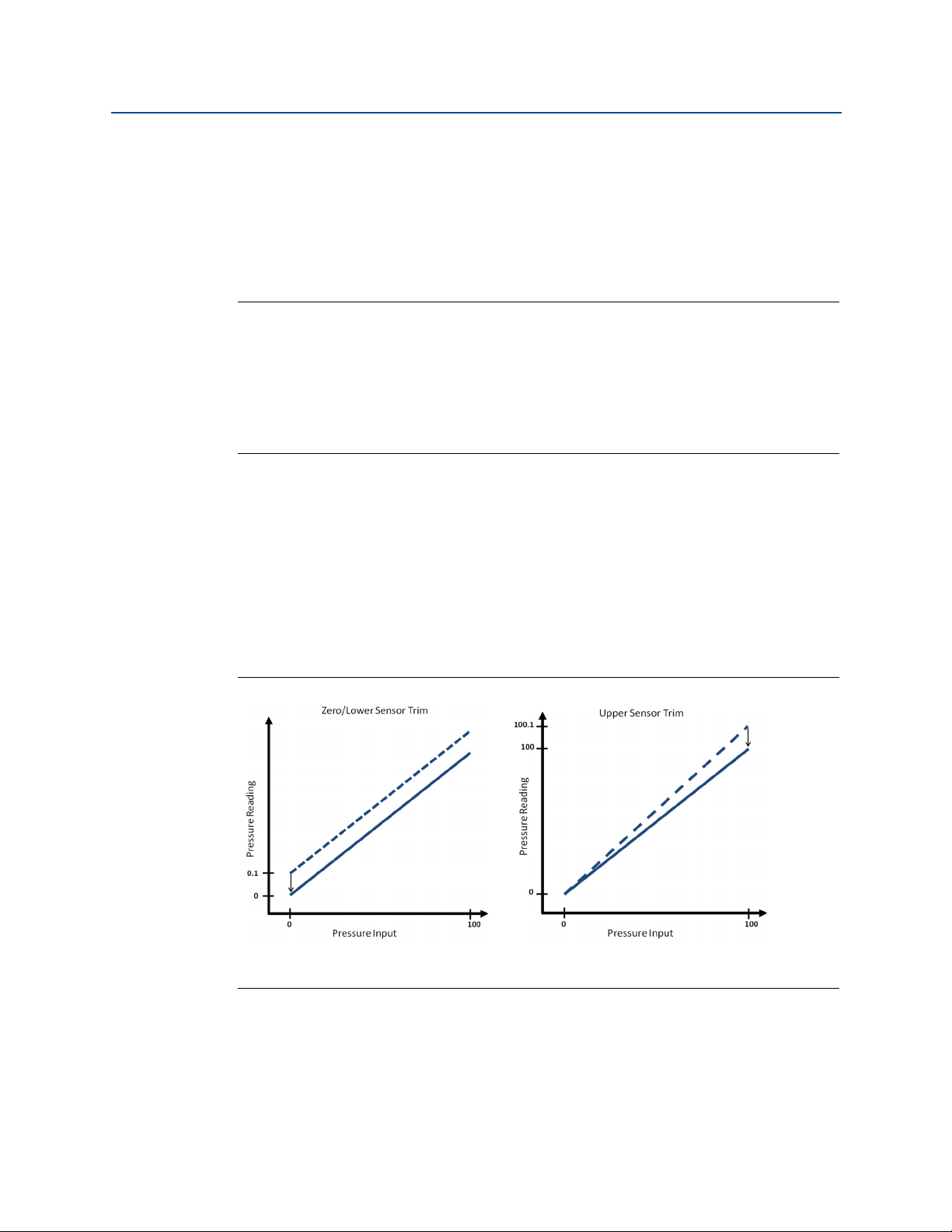
4.3.2 Sensor trim overview
28
A sensor trim corrects the pressure offset and pressure range to match a pressure standard.
The upper sensor trim corrects the pressure range and the lower sensor trim (zero trim)
corrects the pressure offset. An accurate pressure standard is required for full calibration. A
zero trim can be performed if the process is vented.
Operation and Maintenance
Page 35
Reference Manual
A
B
B
A
00809-0100-4045, Rev AB
Zero trim is a single-point offset adjustment. It is useful for compensating for mounting
position effects and is most effective when performed with the device installed in its final
mounting position. Since this correction maintains the slope of the characterization curve,
it should not be used in place of a sensor trim over the full sensor range.
When performing a zero trim, ensure that the equalizing valve is open and all wet legs are
filled to the correct levels. Line pressure should be applied to the device during a zero trim
to eliminate line pressure errors. Refer to “Manifold operation” on page 12.
Note
Do not perform a zero trim on the Rosemount Wireless Pressure Gauge with absolute
measurement type. Zero trim uses a zero reference against ambient air pressure for gage,
vacuum, and compound pressure devices. While absolute pressure devices reference
absolute zero. To correct mounting position effects on a Wireless Pressure Gauge with
absolute measurement type, perform a low trim within the sensor trim function. The low
trim function provides an offset correction similar to the zero trim function, but it does not
require zero-based input.
Sensor trim is a two-point sensor calibration where two end-point pressures are applied,
and all output is linearized between them. Always adjust the low trim value first to establish
the correct offset. Adjustment of the high trim value provides a slope correction to the characterization curve based on the low trim value. The trim values allow you to optimize
performance over your specified measuring range at the calibration temperature.
Operation and Maintenance
March 2016
During a trim operation, the device is placed in high power refresh mode, which provides
frequent pressure measurement updates. This behavior allows for more accurate
calibration of the device. When the device is in high power refresh mode, the battery power
supply will be depleted more rapidly.
Figure 4-1. Sensor Trim Example
A. Before trim
B. After trim
Operation and Maintenance
29
Page 36

Operation and Maintenance
March 2016
4.3.3 Sensor trim
When performing a sensor trim, both the upper and lower limits can be trimmed. If both
upper and lower trims are to be performed, the lower trim must be done before the upper
trim.
Note
Use a pressure input source at least four times more accurate than the device, and allow the
input pressure to stabilize for 60 seconds before entering any values.
From the HOME screen, enter the Fast Key sequence
Reference Manual
00809-0100-4045, Rev AB
Fast Keys
1. Assemble and power the entire calibration system including the gauge, Field
Communicator or AMS Device Manager, power supply, pressure input source, and
readout device.
2. From the Home screen, select 2: Configure.
3. Select 2: Advanced Setup.
4. Select 1: Measurements.
5. Select 1: Dial/Pressure.
6. Select 1: Verify/Calibrate.
Note
Select pressure points so that lower and upper values are equal to or outside the expected
process operation range.
7. Follow the on-screen instructions to complete the adjustment of the lower value.
8. Repeat the procedure for the upper value.
2, 2, 1, 1, 1
Performing a digital zero trim
30
Devices are factory-calibrated. Once installed, it is recommended to perform this step to
eliminate potential error caused by mounting position or static pressure. Instructions for
using a Field Communicator are listed below.
1. Vent the device.
2. Connect the Field Communicator.
3. From the HOME screen, enter the HART
Fast Keys
4. Follow the commands to perform the procedure.
2, 1, 1
®
Fast Key sequence.
Operation and Maintenance
Page 37

Reference Manual
00809-0100-4045, Rev AB
4.3.4 Dial adjustment
Dial adjustment can be used to adjust the dial above or below zero and allows for
adjustments up to 13% of span.
Note
Dial adjustment adjusts the position of the factory dial calibration. It is possible to degrade
the performance of the gauge if the operation is done improperly or inaccurately.
From the HOME screen, enter the Fast Key sequence
Operation and Maintenance
March 2016
Fast Keys
2, 2, 1, 1, 1, 1
1. Select 2: Configure.
2. Select 2: Advanced Setup.
3. Select 1: Measurements.
4. Select 1: Dial/Pressure.
5. Select 1: Verify/Calibrate.
6. Select 1: Verify/Calibrate Dial+Digital Pressure.
7. Adjust dial indicator until it points to lower endpoint.
The following adjustments are available and can be used to complete the dial adjustment.
Fine counter-clockwise (0.1% of Span)
Fine clockwise (0.1% of Span)
Coarse counter-clockwise (0.3% of Span)
Coarse clockwise (0.3% of Span)
8. Select 5: Save Dial.
4.3.5 Recall factory trim—sensor trim
The recall factory trim—sensor trim command allows the restoration of the as-shipped
factory settings of the sensor trim. This command can be useful for recovering from an
inadvertent zero trim of an absolute pressure unit or inaccurate pressure source.
From the HOME screen, enter the Fast Key sequence
Fast Keys
1. Select 3: Service Tools.
2. Select 4: Maintenance.
3. Select 2: Restore to Default Settings.
4. Follow the screen prompts to recall sensor and dial trim.
Operation and Maintenance
3, 4, 2
31
Page 38

Operation and Maintenance
March 2016
4.4 Replacing the battery
The Rosemount Wireless Pressure Gauge shall be used only with the battery
(00G45-9000-0001) supplied by Rosemount. This battery has been officially tested
with the device as required by the I.S. standards during the assessment of the
Rosemount Wireless Pressure Gauge.
The battery is not replaceable in a hazardous location.
Dispose of battery in accordance with local and national jurisdictions.
Procedure to replace the battery:
1. Remove enclosure cover.
2. Switch the device “OFF”.
3. Loosen the screw holding the electronics assembly to the enclosure.
Note
Use caution as the electronics assembly is connected to the pressure sensor via a cable. Take
care not to over stretch this cable as this could damage the device.
Reference Manual
00809-0100-4045, Rev AB
4. Release battery connection from electronics board.
5. Loosen the two screws on the battery holder and slide the battery holder to the
left.
Note
The screws holding down the electronics board do not need to be removed, just loosened.
Take care not to let the battery fall out of the enclosure.
6. Remove battery from enclosure.
7. Installation of new b attery is the reverse of the removal.
32
Operation and Maintenance
Page 39
Reference Manual
Operation and Maintenance
00809-0100-4045, Rev AB
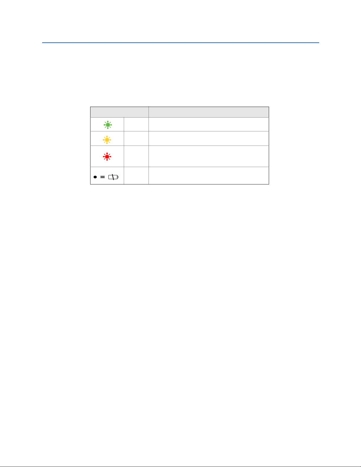
4.5 Local device status and notifications
The flashing LED indicates device status using the colors described in Ta bl e 4 -2 . For start up
considerations, refer to “Turn on device” on page 9.
Table 4-2. Status Descriptions
LED color Device status
Green Functioning properly
Amber Batter y is low, battery replacement recommend ed
Battery replacement required
Red
Device is malfunctioning
No
color
No power, verify ON/OFF switch is in “on” position
If the dial is pointing towards the red “X”, refer to Section 5: Troubleshooting for more
information.
OR
March 2016
Operation and Maintenance
33
Page 40

Operation and Maintenance
March 2016
Reference Manual
00809-0100-4045, Rev AB
34
Operation and Maintenance
Page 41

Reference Manual
00809-0100-4045, Rev AB
Section 5 Troubleshooting
Service support . . . . . . . . . . . . . . . . . . . . . . . . . . . . . . . . . . . . . . . . . . . . . . . . . . . . . . . . . . . page 35
Local troubleshooting . . . . . . . . . . . . . . . . . . . . . . . . . . . . . . . . . . . . . . . . . . . . . . . . . . . . . page 36
Remote troubleshooting . . . . . . . . . . . . . . . . . . . . . . . . . . . . . . . . . . . . . . . . . . . . . . . . . . . page 37
5.1 Service support
To expedite the return process outside of the United States, contact the nearest Emerson™
Process Management representative.
Within the United States, call the Emerson Process Management Instrument and Valve
Response Center using the 1-800-654-RSMT (7768) toll-free number. This center, available
24 hours a day, will assist with any needed information or materials.
Troubleshooting
March 2016
The center will ask for product model and serial numbers, and will provide a Return Material
Authorization (RMA) number. The center will also ask for the process material to which the
product was last exposed.
For inquiries outside of the United States, contact the nearest Emerson Process
Management representative for RMA instructions.
Individuals who handle products exposed to a hazardous substance can avoid injury if
they are informed of and understand the hazard. The product being returned will
require a copy of the required Material Safety Data Sheet (MSDS) for each substance
must be included with the returned goods.
Emerson Process Management Instrument and Valve Response Center representatives will
explain the additional information and procedures necessary to return goods exposed to
hazardous substances.
Troubleshooting
35
Page 42

Troubleshooting
March 2016
Reference Manual
00809-0100-4045, Rev AB
5.2 Local troubleshooting
Table 5-1. Interpreting Local Notifications
LED color Dial location Device status Recommended action(s)
Green
Amber
Red
Black, no color
Functioning properly No action required.
Battery is low Battery replacement recommended.
Investigate active notification via a HART®
Battery is low, device is
malfunctioning
Battery replacement required
OR
Device is malfunctioning
N/A No power Verify ON/OFF switch is in “ON” position.
Communicator. Replace battery if device is
determined to be functioning properly and
notifications have been verified.
Investigate active notification via a HART
Communicator. Replace battery if device is
determined to be functioning properly and
notifications have been verified.
36
Troubleshooting
Page 43

Reference Manual
00809-0100-4045, Rev AB
5.3 Remote troubleshooting
Table 5-2. Interpreting PlantWeb™ Statuses
Troubleshooting
March 2016
PlantWeb
status
Good None Functioning properly No action required
Advisory
Notification Description Recommended action(s)
Database
Storage Error
High Power
Active
Simulate
Active
Non-Critical
User Data
The device has failed to
write to the database
memory at some point in
the past. Any data written
during this time may have
been lost.
The device is operating in a
high power mode. This is
not recommended for this
device.
The device is in simulation
mode and may not be
reporting actual
information.
A user written parameter
does not match its
expected value.
1. Perform a Device Reset.
2. If logging dynamic data is not needed, this advisory
alert can be safely ignored.
3. If the condition persists, replace the device.
1. Disable high power mode.
1. Verify that simulation is no longer required.
2. Disable simulation mode.
3. Reset the device.
1. Restart the device.
2. Reconfirm all configuration items in the device.
3. Restore the default settings and reconfigure device.
4. If the condition persists, replace the device.
Troubleshooting
37
Page 44

Troubleshooting
March 2016
Table 5-2. Interpreting PlantWeb™ Statuses
Reference Manual
00809-0100-4045, Rev AB
PlantWeb
status
Maintenance
Notification Description Recommended action(s)
1. Verify process and ambient temperature is within
the device’s operating range.
Sensor
Tem pe ra tu re
Out of Limits
Pressure Out of
Limits
Vol tage
Conditions Out
of Range
Environmental
Conditions Out
of Range
Capacity
Denied
The sensor temperature
has exceeded its safe
operating range.
The pressure has exceed
the maximum
measurement range.
The supply voltage is low
and may soon affect device
operation.
The device is outside its
normal environmental
operating conditions
which may affect accuracy
and/or proper operation.
The device has failed to
acquire the wireless
communication
bandwidth necessary to
support the configured
update rates.
2. Remote mount the device away from process and
environmental conditions.
3. Reset the device.
4. If the condition persists, replace the device.
1. Check the pressure applied to ensure it is within the
sensor limits.
2. Check the device pressure connection to make sure
it is not plugged or that the isolating diaphragms
are not damaged.
3. If the condition persists, replace the device.
1. Replace the battery.
1. Verify process and ambient temperature is within
the device’s operating range.
2. Remote mount the device away from process and
environmental conditions.
3. Reset the device.
4. If the condition persists, replace the device.
1. Obtaining the bandwidth may take some time
depending on the configured update rates and
other devices in the network. Wait several minutes
to see if the error resolves itself.
2. There may be too many devices attached to the
WirelessHART network, or the update rates may be
too fast. Try using a different network, or slowing
down the update rate on one or more devices.
38
Troubleshooting
Page 45

Reference Manual
00809-0100-4045, Rev AB
Table 5-2. Interpreting PlantWeb™ Statuses
Troubleshooting
March 2016
PlantWeb
status
Failure
Notification Description Recommended action(s)
1.Click on details for more information.
Configuration
Alert
Over-pressure
Seen
Critical Power
Failure
Electronics
Failure
Dial Failure
The device has detected a
configuration error.
The pressure has gone
beyond the maximum
operating limits of the
device, which may have
caused permanent
damage to the sensor.
The supply voltage is too
low for the device to
broadcast updates.
An electronics error that
could impact the device
measurement reading has
occurred.
The device is no longer
able to validate the
position of the dial.
2. Correct the parameter that has a configuration
error.
3. Reset the device.
4. If the condition persists, replace the device.
1. Check the pressure applied to ensure it is within the
sensor limits.
2. Check the device pressure connection to make sure
it is not plugged or that the isolating diaphragms
are not damaged.
3. Acknowledge the over pressure condition to clear
the latched indication, and verify the integrity of
the sensor.
4. If the condition persists, replace the device.
1. Replace the battery.
1.Restore device to default settings.
2. Perform a Device Reset.
3. If the condition persists, replace the device.
1. Reset the device.
2. If condition persists, replace the device.
Troubleshooting
39
Page 46

Troubleshooting
March 2016
Reference Manual
00809-0100-4045, Rev AB
40
Troubleshooting
Page 47

Specifications and Reference Data
March 2016
Reference Manual
00809-0100-4045, Rev AB
Appendix A Specifications and Reference
Data
Physical specifications . . . . . . . . . . . . . . . . . . . . . . . . . . . . . . . . . . . . . . . . . . . . . . . . . . . page 41
Operating specifications . . . . . . . . . . . . . . . . . . . . . . . . . . . . . . . . . . . . . . . . . . . . . . . . . page 42
Dial update rate . . . . . . . . . . . . . . . . . . . . . . . . . . . . . . . . . . . . . . . . . . . . . . . . . . . . . . . . . page 43
Dimensional Drawings . . . . . . . . . . . . . . . . . . . . . . . . . . . . . . . . . . . . . . . . . . . . . . . . . . . page 44
Ordering Information . . . . . . . . . . . . . . . . . . . . . . . . . . . . . . . . . . . . . . . . . . . . . . . . . . . . page 45
Specifications
A.1 Physical specifications
A.1.1 Material selection
Emerson™ Process Management provides a variety of
™
Rosemount
configurations including materials of construction that can
be expected to perform well in a wide range of applications.
The Rosemount product information presented is intended
as a guide for the purchaser to make an appropriate
selection for the application. It is the purchaser’s sole
responsibility to make a careful analysis of all process
parameters (such as all chemical components,
temperature, pressure, flow rate, abrasives, contaminants,
etc.), when specifying product materials, options, and
components for the particular application. Emerson Process
Management is not in a position to evaluate or guarantee
the compatibility of the process fluid or other process
parameters with the product options, configuration, or
materials of construction selected.
A.1.2 Dial size
4.5-in. (114.3 millimeter)
A.1.3 Scale ranges
From vacuum up to 4,000 psi (275 bar)
Single scale considerations
The number of major graduations is a direct result of the
specified combination of Primary Engineering Unit and
Scale Range. There are always 10 minor graduations
between each major graduation.
products with various product options and
Dual scale considerations
The number of major graduations on the inner scale is the
direct result of the combination of Primary Engineering
Unit and Secondary Engineering Unit. There are always five
minor graduations between each major graduation.
A.1.4 Process connections
1
/2-14 NPT male, G1/2 male (EN 837)
A.1.5 Field Communicator connections
Communication terminals are accessible by removing
cover.
A.1.6 Material of construction
Housing
Engineered Polymer, NEMA 4X and IP66/67
Cover O-ring
Silicone rubber
Process-wetted parts
316L SST, Alloy C-276
A.1.7 Shipping weight
1.8 lb (0.82 kg)
Options
Mounting bracket (Code B4)
1.0 lb (0.5 kg)
Rosemount 1199 Seal Systems
Specifications and Reference Data
Reference the Rosemount DP Level Product Data Sheet
for shipping weights.
41
Page 48

Reference Manual
00809-0100-4045, Rev AB
Specifications and Reference Data
March 2016
Rosemount 306 Integrated Manifolds
Reference the Rosemount Manifolds Product Data
Sheet for shipping weights.
A.2 Operating specifications
A.2.1 Conformance to specification (±3
[Sigma])
Technology leadership, advanced manufacturing
techniques, and statistical process control ensure
specification conformance to at least ±3 .
A.2.2 Accuracy
ASME B40.1 – Grade 2A (0.5% of span)
A.2.3 Temperature limits
Ambient
-40 to 185 °F (-40 to 85 °C)
Storage
-40 to 185 °F (-40 to 85 °C)
A.2.6 Burst pressure limit
Up to 11,000 psi (758 bar)
A.2.7 Minimum span limits for percent of
range engineering unit
The maximum rangedown is 10:1. The device maintains
reference accuracy specification up to 6:1 rangedown. After
6:1 rangedown the reference accuracy decreases to 1% of
span.
Scale range Span (6:1 ratio)
5 – 30 psi
(0.35 – 2 bar)
31 – 150 psi
(2.1 – 10.3 bar)
151 – 800 psi
(10.4 – 55.1 bar)
801 – 4,000 psi
(55.2 – 275 bar)
5 psi (0.34 bar) 3 psi (0.21 bar)
25 psi (1.72 bar) 15 psi (1.03 bar)
134 psi (9.24 bar) 80 psi (5.51 bar)
667 psi (45.99 bar)
Minimum span
(10:1 ratio)
400 psi
(27.5 bar)
Process
-40 to 250 °F (-40 to 121 °C)
(1)(2)
A.2.4 Electrical connections/battery
Replaceable, non-rechargeable, 3.6V primary cell,
lithium-thionyl chloride battery
10-year battery life at reference conditions
(3)
A.2.5 Overpressure limit
Maximum
Scale range
working
pressure
5 – 30 psi
(0.35 – 2 bar)
31 – 150 psi
(2.1 – 10.3 bar)
151 – 800 psi
(10.4 – 55.1 bar)
801 – 4,000 psi
(55.2 – 275 bar)
1. Process temperatures above 185 °F (85 °C) require de-rating the
ambient limits by a 1.5:1 ratio.
2. 220 °F (104 °C) limit in vacuum service; 130 °F (54 °C) for pressures
below 0.5 psia.
3. Reference conditions are 70 °F (21 °C), Stable operating pressure
with periodic changes, transmit rate of once per minute, and routing
data for three additional network devices.
30 psi
(2 bar)
150 psi
(10.3 bar)
800 psi
(55.1 bar)
4,000 psi
(275 bar)
Maximum
overpressure
limit
750 psi
(51.7 bar)
1,500 psi
(103.4 bar)
1,600 psi
(110.3 bar)
6,000 psi
(413.7 bar)
A.2.8 Ambient temperature effect per 18 °F
(10 °C)
Scale range
Wireless pressure gauge
Up to 4,000 psi (275 bar) ±0.3 of span
Wireless pressure gauge with remote seal
Up to 4,000 psi (275 bar)
Ambient temperature
effect
See Instrument Toolkit
software.
™
A.2.9 Digital zero trim
An offset adjustment to compensate for mounting position
effects, up to 5% of Span
A.2.10 Humidity limits
0-95% relative humidity
A.2.11 Electromagnetic compatibility (EMC)
Meets all relevant requirements of CE 61326-1: 2006.
A.2.12 Status indication
Device status is indicated by local LED. Reference Wireless
Pressure Gauge Quick Start Guide (document number
00825-0100-4045) for further detail.
42
Specifications and Reference Data
Page 49

Specifications and Reference Data
March 2016
Reference Manual
00809-0100-4045, Rev AB
A.2.13 Output
IEC 62591 (WirelessHART), 2.4 GHz DSSS
A.2.14 Wireless radio (internal antenna)
Frequency: 2.400 – 2.480 GHz
Channels: 15
Modulation: IEEE 802.15.4 compliant DSSS
Transmission: Maximum of 10 dBm EIRP
Integrated omni-directional antenna
A.2.15 Wireless update rate
Wireless update rate is user-selectable from one minute to
60 minutes and is separate from local display.When wireless
is activated, the update rate defaults to once a minute.
A.2.16 Vibration effect
No significant effect when tested per IEC60770-1 or ASME
B40.1 requirements
IEC60770-1 high vibration level - field or pipeline: 10-60 Hz
0.21 mm displacement peak amplitude/60-2000 Hz 3 g
A.2.17 Dial update rate
Dial update rate is user-selectable for four seconds or two
seconds and is separate from the wireless update rate.
Factory default is four seconds.
A.3 Wireless connectivity out-of-the-box
Products in order
Rosemount Wireless Pressure Gauge Automatically Manual activation required
Rosemount Wireless Pressure Gauge Customer specified Activated
Rosemount Wireless Pressure Gauge and
Emerson Smart Wireless Gateway
Network ID & Join Key
are generated
Automatically (matching) Manual activation required
Wireless connectivity
out of the box
A.4 Spare parts
Description Part number
Battery 00G45-9000-0001
Battery retainer 00G45-9000-0002
Screws for retainer and shroud 00G45-9000-0003
Cover assembly
(inlcudes cover and O-ring)
Cover O-ring 00G45-9001-0002
00G45-9001-0001
Specifications and Reference Data
43
Page 50
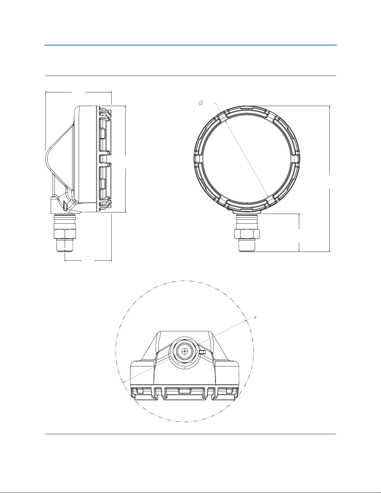
Reference Manual
7.5
[191]
1.96
[49,8]
4.5
[114]
3.4
[86]
2.4
[61]
5.5
[139]
10.4
[264]
00809-0100-4045, Rev AB
Dimensional Drawings
Figure A-1. Rosemount Wireless Pressure Gauge
Specifications and Reference Data
March 2016
Dimensions are in inches (millimeters).
44
Specifications and Reference Data
Page 51

Specifications and Reference Data
March 2016
Ordering Information
Table A-1. Rosemount Wireless Pressure Gauge Ordering Information
H The Standard offering represents the most common options. The starred options (H) should be selected for best
delivery. The Expanded offering is subject to additional delivery lead time.
Model Device type
Reference Manual
00809-0100-4045, Rev AB
WPG Wireless Pressure Gauge
Dial size
45 4.5-in. (114.3 mm)
Gauge output
X Wireless with user-configurable update rate, 2.4 GHz DSSS, WirelessHART
Product certifications
I1 ATEX Intrinsic Safety
I5 US Intrinsically Safe
I6 Canada Intrinsically Safe
I7 IECEx Intrinsic Safety
NA No approval
Measurement type
G Gage
A Absolute
C Compound
V Vacuum
H
H
H
H
H
H
H
H
H
H
H
H
Process connection style
(1)
Connection style Wetted parts material
11
12
1
/2-14 NPT male 316L SST
1
/2-14 NPT male Alloy C-276
21 G1/2 male (EN 837) 316L SST
22 G1/2 male (EN 837) Alloy C-276
Primary engineering unit
A psi
B kiloPascals (kPa)
D bar
E mBar
F MegaPascals (MPa)
G inH2O
H kg/cm
Specifications and Reference Data
2
H
H
H
H
H
H
H
H
H
H
H
H
45
Page 52

Reference Manual
Specifications and Reference Data
00809-0100-4045, Rev AB
Table A-1. Ro s em o u n t W ireless Pressure Gauge Ordering Information
H The Standard offering represents the most common options. The starred options (H) should be selected for best
delivery. The Expanded offering is subject to additional delivery lead time.
I ftH2O
J mmH2O
March 2016
K inHg
L cmH2O
M cmHg
N mmHg
(2)(3)
P
Percent of range (% of range)
Scale ranges
Reference tables in Pressure scale ranges section for scale ranges by engineering unit.
Options (include with selected model number)
Secondary engineering unit (dual scale)
(4)
DA
(4)
DB
(4)
DD
(4)
DH
(2)(3)(5)(6)
DC
Manifolds assemblies
psi
kiloPascals (kPa)
bar
2
kg/cm
Custom units
(7)(8)(9)
H
H
H
H
H
H
H
H
H
H
S5 Assemble to Rosemount 306 Integral Manifold
Diaphragm seal assembly
(8)(9)(10)
S1 Assemble to one Rosemount 1199 Diaphragm Seal
Extended product warranty
WR3 3-year limited warranty
WR5 5-year limited warranty
Mounting bracket
B4 Bracket for 2-in. pipe or panel mounting, all SST
Custom configuration
C1 Custom configuration
46
H
H
H
H
Specifications and Reference Data
Page 53

Specifications and Reference Data
March 2016
Table A-1. Rosemount Wireless Pressure Gauge Ordering Information
H The Standard offering represents the most common options. The starred options (H) should be selected for best
delivery. The Expanded offering is subject to additional delivery lead time.
Calibration certification
Reference Manual
00809-0100-4045, Rev AB
Q4 Calibration certificate
Material traceability certification
Q8 Material traceability certification per EN 10204 3.1
NACE certificate
Q15 Certificate of compliance to NACE® MR0175/ISO 15156 for wetted materials
Q25 Certificate of compliance to NACE MR0103 for wetted materials
1. Materials of Construction comply with recommendations per NACE MR0175/ISO 15156 for sour oil field production environments. Environmental
limits apply to certain materials. Consult latest standard for details. Selected materials also conform to NACE MR0103 for sour refining environments.
2. Not available with Measurement Type Compound.
3. Not available with Measurement Type Vacuum.
4. Not available with Primary Engineering Unit “P” (Percent of Range).
5. Requires Primary Engineering Unit of “A” (psi) or “D” (bar).
6. Requires Custom Configuration mo del code “C1”.
7. Requires Process Connection Style “11” or “12”.
8. Integrated manifold and diaphragm seal assemblies cannot be combined.
9. “Assemble-to” items are specified separately and require a completed model number.
10. Requires Process Connetion 11.
H
H
H
H
Specifications and Reference Data
47
Page 54

Reference Manual
Specifications and Reference Data
00809-0100-4045, Rev AB
A.5 Pressure scale ranges
Additional scale ranges available. Contact Emerson Process Management for additional information.
March 2016
Psi
Code Vacuum
000000 -15/0
Gage/absolute Compound
000005 5 5
000010 10 10
000015 15 15
000020 20 20
000030 30 30
000050 50 50
000060 60 60
000075 75 75
000100 100 100
000150 150 150
000160 160 160
000200 200 200
000300 300 300
(1)
Bar-kg/cm2
Code Vacuum
000000 -1/0
Gage/absolute Compound
000000D40 0.4 0.4
000000D60 0.6 0.6
000001 1 1
000001D50 1.5 1.5
000001D60 1.6 1.6
000002 2 2
000002D50 2.5 2.5
000003 3 3
000004 4 4
000005 5 5
000006 6 6
000009 9 9
000010 10 10
000400 400 N/A
000500 500 N/A
000600 600 N/A
000800 800 N/A
001000 1000 N/A
001500 1500 N/A
002000 2000 N/A
003000 3000 N/A
004000 4000 N/A
1. Vacuum scale will be in inHg and positive pressure in psi. Only
applies to psi.
000015 15 15
000016 16 16
000020 20 20
000024 24 N/A
000025 25 N/A
000040 40 N/A
000050 50 N/A
000060 60 N/A
000070 70 N/A
000100 100 N/A
000160 160 N/A
000250 250 N/A
48
Specifications and Reference Data
Page 55

Specifications and Reference Data
March 2016
Reference Manual
00809-0100-4045, Rev AB
kiloPascals (kPa)
Code Vacuum
000000 -100/0
Gage/absolute Compound
000040 40 40
000060 60 60
000100
000150 150 150
000160 160 160
000200 200 200
000250 250 250
000300 300 300
000400 400 400
000500 500 500
000600 600 600
000900 900 900
001000 1000 1000
001500 1500 1500
001600 1600 1600
002000 2000 2000
002400 2400 N/A
002500 2500 N/A
004000 4000 N/A
005000 5000 N/A
006000 6000 N/A
010000 10000 N/A
025000 25000 N/A
100
100
mbar
Code Vacuum
000000 -1000/0
Gage/absolute Compound
000400 400 400
000600 600 600
001000 1000 1000
001500 1500 1500
002000 2000 2000
003000 3000 3000
004000 4000 4000
005000 5000 5000
006000 6000 6000
009000 9000 9000
MegaPascals (MPa)
Code Vacuum
000000 -0.1/0
Gage/absolute Compound
000000D20 0.2 0.2
000000D50 0.5 0.5
000001 1 1
000001D50 1.5 1.5
000002 2 2
000002D50 2.5 N/A
inH2O
Code Vacuum
000000 -400/0
Gage/absolute Compound
Specifications and Reference Data
000200 200 200
000300 300 300
000800 800 800
49
Page 56

Reference Manual
00809-0100-4045, Rev AB
Specifications and Reference Data
March 2016
ftH2O
Code Vacuu m
000000 -30/0
Gage/absolute Compound
000035 35 35
000060 60 60
000070 70 70
000100 100 100
000140 140 140
000240 240 240
000400 400 400
000500 500 500
000700 700 700
000900 900 N/A
mmH2O
Code Vacuu m
000000 -10000/0
cmH2O
Code Vacuum
000000 -1000/0
Gage/absolute Compound
000500 500 500
000900 900 900
cmHg
Code Vacuum
000000 -75/0
Gage/absolute Compound
000150 150 150
000750 750 750
004000 4000 N/A
020000 20000 N/A
mmHg
Code Vacuum
000000 -750/0
Gage/absolute Compound
007500 7500 7500
040000 40000 40000
200000 200000 200000
inHg
Code Vacuu m
000000 -30/0
Gage/absolute Compound
000012 12 12
000015 15 15
000016 16 16
000020 20 20
000030 30 30
000060 60 60
000300 300 300
Gage/absolute Compound
001500 1500 1500
007500 7500 7500
040000 40000 N/A
200000 200000 N/A
Percent of range
Code Gage/absolute
000030 30
000150 150
000800 800
004000 4000
1. Scale will read 0-100%. Code selected is representative of the
desired working pressure range in psi.
(1)
50
Specifications and Reference Data
Page 57

Product Certifications
March 2016
Reference Manual
00809-0100-4045, Rev AB
Appendix B Product Certifications
Rev 1.0
European Union Directive Information . . . . . . . . . . . . . . . . . . . . . . . . . . . . . . . . . . . . . . . page 51
Telecommunication compliance . . . . . . . . . . . . . . . . . . . . . . . . . . . . . . . . . . . . . . . . . . . . page 51
FCC and IC . . . . . . . . . . . . . . . . . . . . . . . . . . . . . . . . . . . . . . . . . . . . . . . . . . . . . . . . . . . . . . . page 51
Ordinary location certification from CSA . . . . . . . . . . . . . . . . . . . . . . . . . . . . . . . . . . . . . page 51
Installing in North America . . . . . . . . . . . . . . . . . . . . . . . . . . . . . . . . . . . . . . . . . . . . . . . . . page 51
B.1 European Union Directive Information
A copy of the EC Declaration of Conformity can be found at
the end of the Quick Start Guide. The most recent revision
of the EC Declaration of Conformity can be found at
EmersonProcess.com/Rosemount
.
B.2 Telecommunication compliance
All wireless devices require certification to ensure that they
adhere to regulations regarding the use of the RF spectrum.
Nearly every country requires this type of product
certification. Emerson is working with governmental
agencies around the world to supply fully compliant
products and remove the risk of violating country directives
or laws governing wireless device usage.
B.3 FCC and IC
This device complies with Part 15 of the FCC Rules.
Operation is subject to the following conditions: This
devices may not cause harmful interference, this devices
must accept any interference received, including
interference that may cause undesired operation. This
device must be installed to ensure a minimum antenna
separation distance of 20 cm from all persons. This device
complies with Industry Canada license-exempt RSS-247.
Operation is subject to the following two conditions: (1)
this device may not cause interference, and (2) this device
must accept any interference, including interference that
may cause undesired operation of the device.
Changes or modification to the equipment not expressly
approved by Emerson Process Management could void the
user's authority to operate the equipment.
Cet appareil est conforme à la Partie 15 de la
réglementation FCC. Son fonctionnement est soumis aux
conditions suivantes: Cet appareil ne doit pas causer
d'interférences nuisibles. Cet appareil doit accepter toute
interférence reçue, incluant toute interférence pouvant
causer un fonctionnement indésirable. Cet appareil doit
être installé pour assurer une distance minimum de
l'antenne de séparation de 20 cm de toute personne. Cet
appareil est conforme à la norme RSS-247 Industrie Canada
exempt de licence. Son fonctionnement est soumis aux
deux conditions suivantes: (1) cet appareil ne doit pas
provoquer d'interférences et (2) cet appareil doit accepter
toute interférence, y compris les interférences pouvant
causer un mauvais fonctionnement du dispositif. Les
changements ou les modifications apportés à l'équipement
qui n'est pas expressément approuvé par Emerson Process
Management pourraient annuler l'autorité de l'utilisateur à
utiliser cet équipement.
B.4 Ordinary location certification from CSA
The product has been examined and tested to determine
that the design meets the basic electrical, mechanical, and
fire protection requirements by CSA, a nationally
recognized test laboratory (NRTL) as accredited by the
Federal Occupational Safety and Health Administration
(OSHA).
B.5 Installing in North America
The US National Electrical Code (NEC) and the Canadian
Electrical Code (CEC) permit the use of Division marked
equipment in Zones and Zone marked equipment in
Divisions. The markings must be suitable for the area
classification, gas, and temperature class. This information
is clearly defined in the respective codes.
Product Certifications
51
Page 58

Reference Manual
00809-0100-4045, Rev AB
Product Certifications
March 2016
B.5.1 USA
I5 U.S.A. Intrinsically Safe (IS)
Certificate: [CSA] 70047656
Standards: FM 3600 – 2011, FM 3610 – 2010, UL Standard
50 – Eleventh Edition, UL 61010-1 – 3rd Edition,
ANSI/ISA-60079-0 (12.00.01) – 2013,
ANSI/ISA-60079-11 (12.02.01) – 2013, ANSI/IEC
60529 – 2004
Markings: IS CL I, DIV 1, GP A, B, C, D T4;
Class 1, Zone 0, AEx ia IIC T4 Ga;
T4 (-40°C
when installed per Rosemount drawing
00G45-1020;
Type 4X; IP66/67;
Special Conditions for Safe Use (X):
1. Do not replace battery when explosive atmosphere is
present
2. Use only 00G45-9000-0001 batteries
3. The surface resistivity of the housing is greater than
1G . To avoid electrostatic charge build-up, it must
not be rubbed or cleaned with solvents or a dry cloth.
4. Substitution of components may impair intrinsic
safety
Ta +70°C)
B.5.2 Canada
I6 Canada Intrinsically Safe (IS)
Certificate: [CSA] 70047656
Standards: CAN/CSA C22.2 No. 0-10, CAN/CSA C22.2 No.
94-M1991 (R2011), CAN/CSA-60079-0-11,
CAN/CSA-60079-11-14, CSA Std C22.2 No.
60529-05, CAN/CSA-C22.2 No. 61010-1-12
Markings: Intrinsically Safe for Class I, Division 1, Groups A,
B, C, D T4;
Ex ia IIC T4 Ga
T4 (-40°C
when installed per Rosemount drawing
00G45-1020;
Type 4X; IP66/67;
Ta +70°C)
Special Conditions for Safe Use (X):
1. Do not replace battery when explosive atmosphere is
present.
Ne pas remplacer les accumulateurs si une
atmosphère explosive peut être présente.
2. Use only 00G45-9000-0001 batteries.
Utiliser uniquement des accumulateurs
00G45-9000-0001.
3. The surface resistivity of the housing is greater than
1G . To avoid electrostatic charge build-up, it must
not be rubbed or cleaned with solvents or a dry cloth.
La résistivité de surface du boÎtier est supérieure à un
gigaohm. Pour éviter l’accumulation de charge
électrostatique, ne pas frotter ou nettoyer avec des
produits solvants ou un chiffon sec.
4. Substitution of components may impair intrinsic
safety.
La substitution de composants peut compromettre la
sécurité intrinsèque.
B.5.3 Europe
I1 ATEX Intrinsic Safety
Certificate: Baseefa16ATEX0005X
Standards: EN 60079-0: 2012 + A11: 2013, EN 60079-11:
2012
Markings:
Special Conditions for Safe Use (X):
1. The plastic enclosure may constitute a potential
electrostatic ignition risk and must not be rubbed or
cleaned with a dry cloth.
2. The measured capacitance between the equipment
enclosure and metallic inline sensor module is 4.7pF.
This must be considered only when the WPG is
integrated into a system where the process
connection is not grounded.
3. Do not change the battery when an explosive
atmosphere is present.
4. Only replace battery with Rosemount Part No.
00G45-9000-0001.
II 1 G Ex ia IIC T4 Ga, T4 (-40°C Ta +70°C)
IP66/67;
B.5.4 International
I7 IECEx Intrinsic Safety
Certificate: IECEx BAS 16.0012X
Standards: IEC 60079-0: 2011, IEC 60079-11: 2011
Markings: Ex ia IIC T4 Ga, T4 (-40°C
IP66/67;
52
Ta +70°C)
Product Certifications
Page 59

Product Certifications
March 2016
Special Conditions for Safe Use (X):
1. The plastic may constitute a potential electrostatic
ignition risk and must not be rubbed or cleaned with a
dry cloth.
2. The measured capacitance between the equipment
enclosure and metallic inline sensor module is 4.7pF.
This must be considered only when the WPG is
integrated into a system where the process
connection is not grounded.
3. Do not change the battery when an explosive
atmosphere is present.
4. Only replace battery with Rosemount Part No.
00G45-9000-0001.
Reference Manual
00809-0100-4045, Rev AB
Product Certifications
53
Page 60

Reference Manual
00809-0100-4045, Rev AB
Figure B-1. Rosemount Wireless Pressure Gauge Installation Drawing
Product Certifications
March 2016
54
Product Certifications
Page 61

Field Communicator Menu Trees
March 2016
Reference Manual
00809-0100-4045, Rev AB
Appendix C Field Communicator Menu
Trees
C.1 Overview
Figure C-1. Overview
Field Communicator Menu Trees
55
Page 62

Reference Manual
00809-0100-4045, Rev AB
Figure C-2. Configure
Field Communicator Menu Trees
March 2016
Figure C-3. Service Tools
56
Field Communicator Menu Trees
Page 63

Field Communicator Menu Trees
March 2016
Figure C-4. Device Information
Reference Manual
00809-0100-4045, Rev AB
Figure C-5. Device Information (continued)
Field Communicator Menu Trees
57
Page 64

Reference Manual
00809-0100-4045, Rev AB
Field Communicator Menu Trees
March 2016
58
Field Communicator Menu Trees
Page 65

Network Design Best Practices
March 2016
Reference Manual
00809-0100-4045, Rev AB
Appendix D Network Design Best
Practices
Overview . . . . . . . . . . . . . . . . . . . . . . . . . . . . . . . . . . . . . . . . . . . . . . . . . . . . . . . . . . . . . . . . page 59
Effective range . . . . . . . . . . . . . . . . . . . . . . . . . . . . . . . . . . . . . . . . . . . . . . . . . . . . . . . . . . . page 59
D.1 Overview
All recommended practices should be followed to ensure highest data reliability. Deviation
from these best practices may require device repeaters in the network to maintain 99% data
reliability. The following are guidelines to achieve the best possible wireless network.
Each wireless network field should be scoped to a single process unit.
Minimize the number of hops to the Gateway in order to reduce latency. A
minimum of five wireless instruments should be within effective range of the
Emerson
Each device in the network should have at minimum three devices with potential
communication paths. A mesh network gets its reliability from multiple
communication pathways. Ensuring each device has multiple neighbors within
range will result in the most reliable network.
™
Smart Wireless Gateway.
Have 25 percent of wireless instruments in the network within range of Emerson
Wireless Gateway. Other enhancing modifications include creating a higher
percentage of devices within effective range of the gateway to 35 percent or more.
This clusters more devices around the gateway and ensures fewer hops and more
bandwidth available to WirelessHART
Effective range is determined by type of process unit and the density of the
infrastructure that surrounds the network.
D.2 Effective range
Heavy Obstruction: 100 ft. (30 m). Typical heavy density plant environment. Cannot drive a
truck or equipment through.
Medium Obstruction: 250 ft. (76 m). Typical light process areas, lots of space between
equipment and infrastructure.
Light Obstruction: 500 ft. (152 m). Typical of tank farms. Despite tanks being big
obstructions themselves, lots of space between and above makes for good RF propagation.
Line of Sight: 750 ft. (230 m). No obstructions between WirelessHART devices and devices
mounted a minimum of 6 ft. (2 m) above ground or obstructions.
For examples and complete explanations, refer to the IEC62591 WirelessHART System
Engineering Guide
.
®
devices with fast scan rates.
Network Design Best Practices
59
Page 66

Reference Manual
00809-0100-4045, Rev AB
Network Design Best Practices
March 2016
60
Network Design Best Practices
Page 67

Device Variable Index
March 2016
Reference Manual
00809-0100-4045, Rev AB
Appendix E Device Variable Index
This section outlines the most important alerts in the HART® command 48 additional status
™
field for Rosemount
by DeltaV
™
for notification monitoring, and in the Emerson Smart Wireless Gateways for
additional status mapping in Modbus
E.1 Messages and descriptions
A complete list of additional status bits is available in the Gateway.
Table E-1. Devic e Variables
Device variable Index
0 Supply voltage
1Pressure
2Custom
3 Sensor temperature
Wireless Pressure Gauge. The information in this section can be used
®
, OPC, etc.
Ta bl e E - 2 to Ta b l e E- 4 shows a list of the most important messages that may be displayed.
Table E-2. Failures
Message
Radio failure Byte 12 :: Bit 4
Configuration alert Byte 2 :: Bit 6 Device has detected a configuration error
Over-pressure seen Byte 4 :: Bit 0
Critical power failure Byte 6 :: Bit 2
Electronics failure Byte 8 :: Bit 6
Dial failure Byte 4 :: Bit 4
1. Location of the alert in the HART command 48 Additional Status field.
Additional
(1)
status
Description
Wireless radio has detected a failure or stopped
communicating
Pressure has gone beyond the maximum
operating limits of the device, which may have
caused permanent damage to the sensor
Supply voltage is too low for the device to
broadcast updates
Electronics error that could impact the device
measurement reading has occurred
Device has detected a failure or unable to confirm
dial location
Device Variable Index
61
Page 68

Reference Manual
00809-0100-4045, Rev AB
Table E-3. Maintena nce
Device Variable Index
March 2016
Message
Voltage conditions
out of range
Pressure out of
limits
Capacity denied Byte 12 :: Bit 0
Sensor temperature
beyond sensor limits
Environmental
conditions out of
range
1. Location of the alert in the HART command 48 Additional Status field.
Additional
(1)
status
Byte 8 :: Bit 4
Byte 3 :: Bit 5
Byte 3 :: Bit 1
Byte 8 :: Bit 5
Description
Supply voltage is low and may soon affect device
operation
Pressure has exceeded the maximum
measurement range
Device has failed to acquire the wireless
communication bandwidth necessary to support
the configured update rates
Sensor temperature has exceeded its safe
operating range
Device is outside its normal environmental
operating conditions which may affect accuracy
and/or proper operation
Table E-4. Advisory
Message
Database storage
error
Simulation active Byte 8 :: Bit 0
Additional
(1)
status
Byte 0 :: Bit 2
Description
Device has failed to write to the database memory
at some point in the past; any data written during
this time may have been lost
Device is in simulation mode and is not reporting
actual information
High power active Byte 1 :: Bit 7
Non-critical user
data warning
1. Location of the alert in the HART command 48 Additional Status field.
Byte 2 :: Bit 1
Device is operating in a high power mode; this is
not recommended for this device
User-written parameter does not match its
expected value
62
Device Variable Index
Page 69

Page 70

Global Headquarters
Emerson Process Management
6021 Innovation Blvd.
Shakopee, MN 55379, USA
+1 800 999 9307 or +1 952 906 8888
+1 952 949 7001
RFQ.RMD-RCC@EmersonProcess.com
North America Regional Office
Emerson Process Management
8200 Market Blvd.
Chanhassen, MN 55317, USA
+1 800 999 9307 or +1 952 906 8888
+1 952 949 7001
RMT-NA.RCCRFQ@Emerson.com
Latin America Regional Office
Emerson Process Management
1300 Concord Terrace, Suite 400
Sunrise, FL 33323, USA
+1 954 846 5030
+1 954 846 5121
RFQ.RMD-RCC@EmersonProcess.com
Reference Manual
00809-0100-4045, Rev AB
March 2016
Europe Regional Office
Emerson Process Management Europe GmbH
Neuhofstrasse 19a P.O. Box 1046
CH 6340 Baar
Switzerland
+41 (0) 41 768 6111
+41 (0) 41 768 6300
RFQ.RMD-RCC@EmersonProcess.com
Asia Pacific Regional Office
Emerson Process Management Asia Pacific Pte Ltd
1 Pandan Crescent
Singapore 128461
+65 6777 8211
+65 6777 0947
Enquiries@AP.EmersonProcess.com
Middle East and Africa Regional Office
Emerson Process Management
Emerson FZE P.O. Box 17033
Jebel Ali Free Zone - South 2
Dubai, United Arab Emirates
+971 4 8118100
+971 4 8865465
RFQ.RMTMEA@Emerson.com
Linkedin.com/company/Emerson-Process-Management
Twitter.com/Rosemount_News
Facebook.com/Rosemount
Youtube.com/user/RosemountMeasurement
Google.com/+RosemountMeasurement
Standard Terms and Conditions of Sale can be found at:
www.Emerson.com/en-us/pages/Terms-of-Use.aspx
The Emerson logo is a trademark and service mark of Emerson Electric Co.
AMS, DeltaV, Instrument Toolkit, Rosemount, and Rosemount logotype are
trademarks of Emerson Process Management.
HART and WirelessHART are registered trademarks of the FieldComm Group.
NACE is a registered trademark of NACE International.
Modbus is a registered trademark of Gould Inc.
All other marks are the property of their respective owners.
© 2016 Emerson Process Management. All rights reserved.
 Loading...