

World Class 3000 O2 Analyzer with IFT 3000 Intelligent Field Transmitter-Rev 3.6
Table of contents
 Loading...
Rosemount World Class 3000 O2 Analyzer with IFT 3000 Intelligent Field Transmitter-Rev 3.6 Manuals & Guides

WORLD CLASS 3000
OXYGEN ANALYZER
WITH IFT 3000
INTELLIGENT
FIELD TRANSMITTER
Instruction Bulletin IB-106-300NH Rev. 3.6
World Class 3000 Probe
Part No. _______________
Serial No. _______________
Order No. _______________
IFT 3000
Part No. _______________
Serial No. _______________
Order No. _______________
HPS 3000
Part No. _______________
Serial No. _______________
Order No. _______________
MPS 3000
Part No. _______________
Serial No. _______________
Order No. _______________

PAGE SUMMARY
HIGHLIGHTS OF CHANGES
Effective May, 1996 Rev. 3
---
--2-2
3-3
4-1
PAGE SUMMARY
2-3
2-8
2-9
PAGE SUMMARY
1-3
3-21
General. Updated text and art to reflect new IFT version.
General. Inserted new note regarding ambient air and high test gas.
Updated Figure 2-1, Probe Ins tal la ti on (sheet 1 of 5)
Updated system s t atu s codes .
Updated system s t atu s codes .
Updated Figure 2-1, Probe Ins tal la ti on (sheet 2 of 5)
Added Caution regarding n eed f or circu it break er on electrical power supply. Deleted Note on removin g
probe.
Added instruction in Caution to change labeling.
Added description of th e pas s word protection feature for th e IFT.
Added password prot ecti on i n f ormation.
Effective June, 1996 Rev. 3.1
Effective October, 1996 Rev. 3.2
4-1
PAGE SUMMARY
iii
2-1
2-8
2-10
2-15
2-19
2-21
2-22
4-1
Added new st atu s di s plays for password protection f eat u res .
Added "Safety instructions for the wiring and installation of this apparatus".
Added WARNING to read new safety instructions.
Added NOTE regarding IFT fuse locations an d s pecif ication s .
Added NOTE regarding IFT fuse locations to Figure 2-7.
Added NOTE regarding HPS fuse locations and s pecifi cation s.
Added NOTE regarding HPS fuse locations to Figure 2-17.
Added NOTE regarding MPS fuse locations and s pecifi cation s.
Added NOTE regarding MPS fuse specifications to Figure 2-20.
Added WARNING regardin g protect ive covers and grounds.
Effective January, 1997 Rev. 3.3
IB-106-300N H

HIGHLIGHTS OF CHANGES (continued)
Effective May, 1997 Rev. 3.4
PAGE SUMMARY
iii-xv Added foreign language safety sheets.
Effective February, 1998 Rev. 3.5
PAGE SUMMARY
2-2
3-17
PAGE SUMMARY
--1-3
3-7
3-21 through 3-26
Figure 2-1. Changed calibration gas tube dimensions.
Added note on calibration gas flowmeter.
Changed test gas to calibration gas and reference gas to reference air throughout the instruction bulletin.
Deleted paragraph 1-2.d.10.
Figure 3-2 (Sheet 3 of 5). Deleted password protection in formation.
Deleted paragraph 3-12 and Figures 3-7 though 3-10.
Effective July, 1998 Rev. 3.6
IB-106-300N H

ROSEMOUNT WARRANTY
Rosemount warrants that the equipment manufactured and sold by it will, upon shipment, be free of
defects in workmanship or material. Should any failure to conform to this warranty become apparent during a
period of one year after the date of shipment, Rosemount shall, upon prompt written notice fro m the purchaser,
correct such nonconformity by repair or replacement, F.O.B. factory of the defective part or parts. Correction
in the manner provided above shall constitute a fulfillment of all liabilities of Rosemount with respect to the
quality of the equipment.
THE FOREGOING WARRANTY IS EXCLUSIVE AND IN LIEU OF ALL OTHER
WARRANTIES OF QUALITY WHETHER WRITTEN, ORAL, OR IM PLIED (INCLUDING
ANY WARRANTY OF MERCHANTABILITY OF FITNESS FOR PURPOSE).
The remedy(ies) provided above shall be purchaser's sole remedy(ies) for any failure of Rosemount to
comply with th e warranty provisions, w h eth er claims by the purchaser are based in contract or in tort (including
negligence).
Rosemount does not warrant equipment against normal deterioration due to environment. Factors such as
corrosive gases and solid particulates can be detrimental and can create the need for repair or replacement as
part of normal wear and tear during the w a rran ty period.
Equipment supplied by Rosemount Analytical Inc. but not manufactured by it will be subject to the same
warranty as is ex tended to R osemount by the original man u f actu rer.
At the time of installation it is important that the required services are supplied to the system and that the
electronic controller is set up at least to the point where it is controlling the sensor heater. This will ensure, that
should there be a delay between installation and full commissioning that the sensor being supplied with ac
power and reference air will not be subjected to component deterioration.
IB-106-300N H
i
NOTE
Only one probe can be calibrated at a time.
Probe calibrations must be scheduled
appropriately in multiple probe applications.
PURPOSE
The purpose of this manual is to provide a comprehensive understanding of the World Class 3000
Oxygen Analyzer components, functions, installation, and maintenance.
This manual is designed to provide information about the World Class 3000 Oxygen Analyzer. We
recommend that you thoroughly familiarize yourself with the Overview and Installation sections before
installing your emissions monitor.
The overview presents the basic principles of the oxygen analyzer along with its performance
characteristics and components . The remaining sections contain detailed procedures and information necessary
to install and service the oxy g en an alyzer.
Before contacting Rosemount concerning any questions, first consult this manual. It describes most
situations encountered in your equipment's operation and details necessary action.
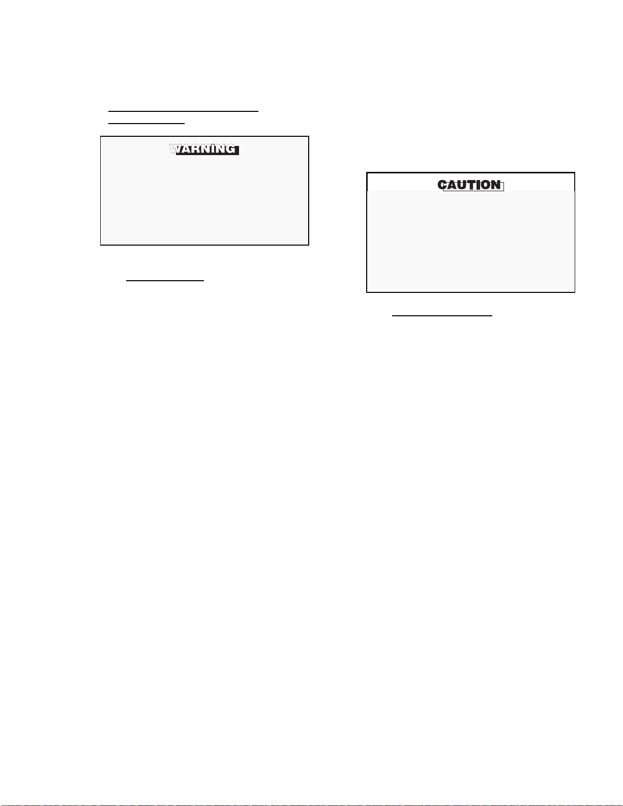
DEFINITIONS
The following definitions apply to WARNINGS, CAUTIONS, and NOTES found throughout this
publication.
Highlights an operation or maintenance
procedure, practice, condition, statement,
etc., that if not strictly observed, could result
in injury, death, or long-term health hazards
of personnel.
NOTE
Highlights an essential operation procedure,
condition, or statemen t.
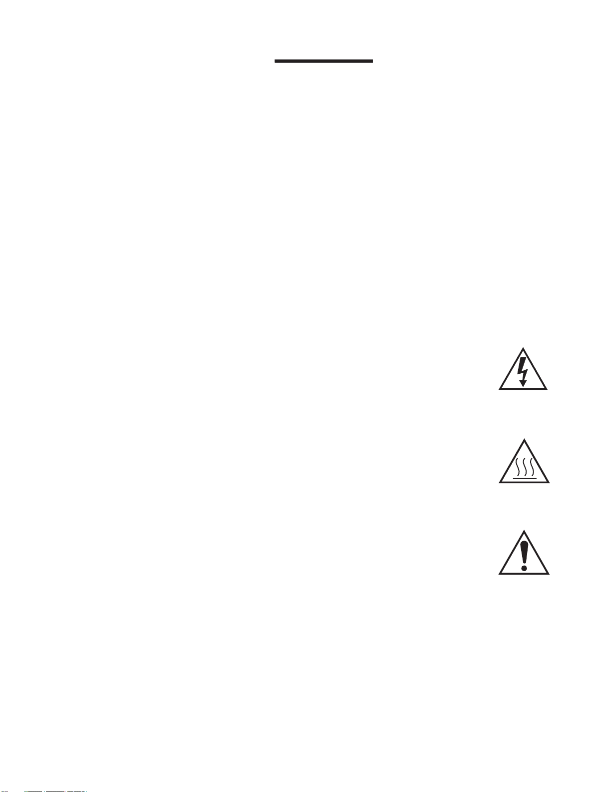
: EARTH (GROUND) TERMINAL
: PROTECTIVE CONDUCTOR TERMINAL
: RISK OF ELECTRICAL SHOCK
: WARNING: REFER TO INSTRUCTION BULLETIN
Highlights an operation or maintenance
procedure, practice, conditions, statement,
etc., that if not strictly observed, could result
in damage to or destruction of equipment, or
loss of effectiveness.
NOTE TO USERS
The number in the low er rig h t corn er of each illu stration in th is pu blication is a manual illustration number.
It is not a part number, and is not related to the illustration in any technical manner.
IB-106-300N H
ii

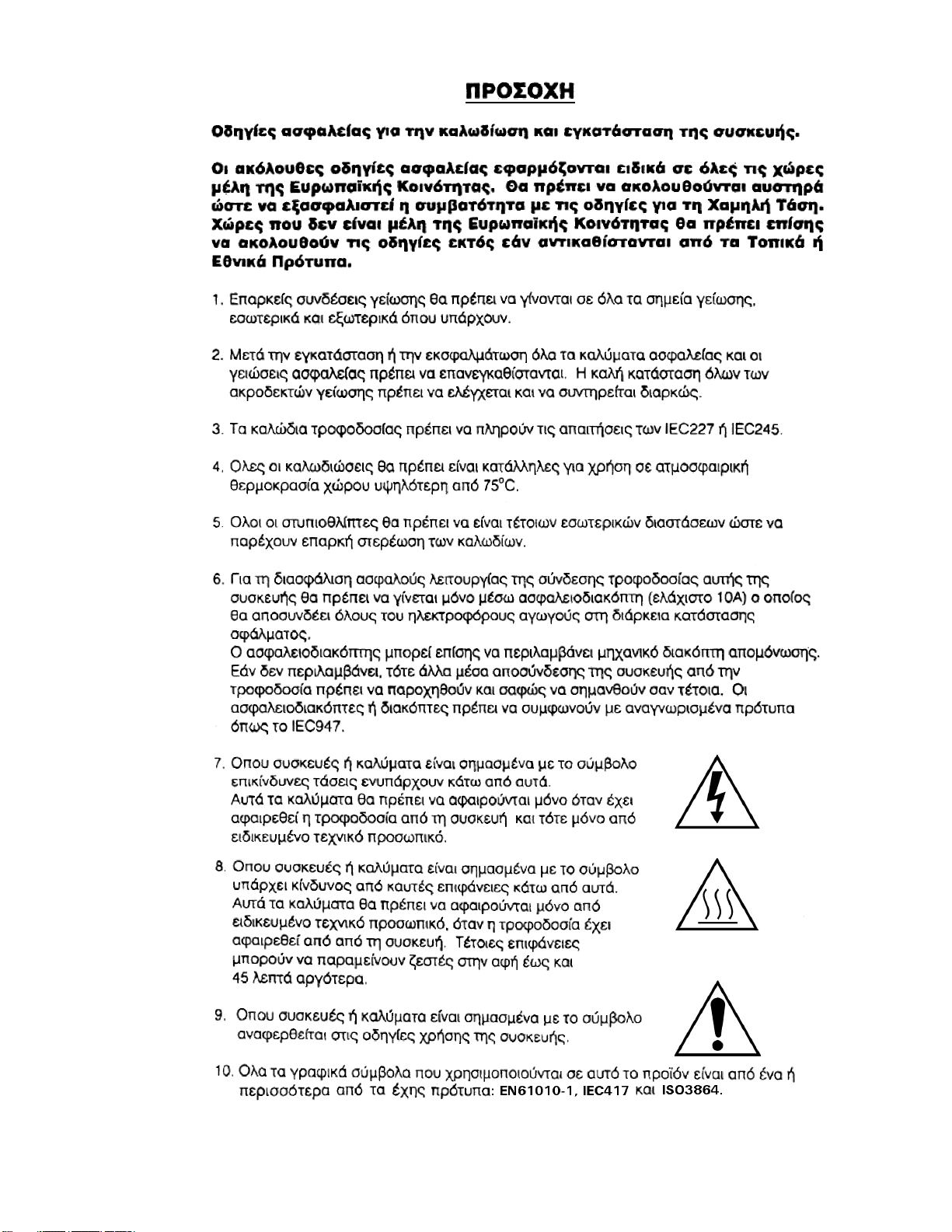
IMPORTANT
SAFETY INSTRUCTIONS FOR THE WIRING AND
INSTALLATION OF THIS APPARATUS
The following safety instructions apply specifically to all EU
member states. They should be strictly adhered to in order to
assure compliance with the Low Voltage Directive. Non-EU
states should also comply with the following unless superseded
by local or National Standards.
1. Adequate earth connections should be made to all earthing points, internal and external, where provided.
2. After installation or troubleshooting, all safety covers and safety grounds must be replaced. The integrity of
all earth terminals must be maintained at all times.
3. Mains supply cords should comply with the requirements of IEC227 or IEC245.
4. All wiring shall be suitable for use in an ambient temperature of greater than 75°C.
5. All cable glands used should be of such internal dimensions as to provide adequate cable anchorage.
6. To ensure safe operation of this equipment, connection to the mains supply should only be made through a
circuit breaker which will disconnect all circuits carrying conductors during a fault situation. The circuit
breaker may also include a mechanically operated isolating switch. If not, then another means of
disconnecting the equipment from the supply must be provided and clearly marked as such. Circuit breakers
or switches must comply with a recognized standard such as IEC947. All wiring must conform with any
local standards.
7. Where equipment or covers are marked with the symbol to the right, hazardous voltages
are likely to be present beneath. These covers should only be removed when power is
removed from the equipment — and then only by trained service personnel.
8. Where equipment or covers are marked with the symbol to the right, there is a danger
from hot surfaces beneath. These covers should only be removed by trained service
personnel when power is removed from the equipment. Certain surfaces may remain hot
to the touch.
9. Where equipment or covers are marked with the symbol to the right, refer to the
Operator Manual for instructions.
10. All graphical symbols used in this product are from one or more of the following standards: EN61010-1,
IEC417, and ISO3864.
IB-106-300N H
iii
BELANGRIJK
Veiligheidsvoorschriften voor de aansluiting en installatie van dit toestel.
De hierna volgende veiligheidsvoorschriften zijn vooral bedoeld voor de EU lidstaten. Hier moet aan
gehouden worden om de onderworpenheid aan de Laag Spannings Richtlijn (Low Voltage Directive) te
verzekeren. Niet EU staten zouden deze richtlijnen moeten volgen tenzij zij reeds achterhaald zouden zijn
door plaatselijke of nationale voorschriften.
1. Degelijke aardingsaansluitingen moeten gemaakt worden naar alle voorziene aardpunten, intern en extern.
2. Na installatie of controle moeten alle veiligheidsdeksels en -aardingen terug geplaatst worden. Ten alle tijde
moet de betrouwbaarheid van de aarding behouden blijven.
3. Voedingskabels moeten onderworpen zijn aan de IEC227 of de IEC245 voorschriften.
4. Alle bekabeling moet geschikt zijn voor het gebruik in omgevingstemperaturen, hoger dan 75°C.
5. Alle wartels moeten zo gedimensioneerd zijn dat een degelijke kabel bevestiging verzekerd is.
6. Om de veilige werking van dit toestel te verzekeren, moet de voeding door een stroomonderbreker gevoerd
worden (min 10A) welke alle draden van de voeding moet onderbreken. De stroomonderbreker mag een
mechanische schakelaar bevatten. Zoniet moet een andere mogelijkheid bestaan om de voedingsspanning
van het toestel te halen en ook duidelijk zo zijn aangegeven. Stroomonderbrekers of schakelaars moeten
onderworpen zijn aan een erkende standaard zoals IEC947.
7. Waar toestellen of deksels aangegeven staan met het symbool is er meestal hoogspanning
aanwezig. Deze deksels mogen enkel verwijderd worden nadat de voedingsspanning werd
afgelegd en enkel door getraind onderhoudspersoneel.
8. Waar toestellen of deksels aangegeven staan met het symbool is er gevaar voor hete
oppervlakken. Deze deksels mogen enkel verwijderd worden door getraind
onderhoudspersoneel nadat de voedingsspanning verwijderd werd. Sommige opppervlakken kunnen 45 minuten later nog steeds heet aanvoelen.
9. Waar toestellen of deksels aangegeven staan met het symbool gelieve het handboek te
raadplegen.
10. Alle grafische symbolen gebruikt in dit produkt, zijn afkomstig uit een of meer van devolgende standaards;
EN61010-1, IEC417 en ISO3864.
IB-106-300N H
iv
VIGTIGT
Sikkerhedsinstruktion for tilslutning og installering af dette udstyr.
Følgende sikkerhedsinstruktioner gælder specifikt i alle EU-medlemslande. Instruktionerne skal nøje
følges for overholdelse af Lavsspændingsdirektivet og bør også følges i ikke EU-lande medmindre andet er
specificeret af lokale eller nationale standarder.
1. Passende jordforbindelser skal tilsluttes alle jordklemmer, interne og eksterne, hvor disse forefindes.
2. Efter installation eller fejlfinding skal alle sikkerhedsdæksler og jordforbindelser reetableres.
3. Forsyningskabler skal opfylde krav specificeret i IEC227 eller IEC245.
4. Alle ledningstilslutninger skal være konstrueret til omgivelsestemperatur højere end 75° C.
5. Alle benyttede kabelforskruninger skal have en intern dimension, så passende kabelaflastning kan etableres.
6. For opnåelse af sikker drift og betjening skal der skabes beskyttelse mod indirekte berøring gennem afbryder
(min. 10A), som vil afbryde alle kredsløb med elektriske ledere i fejlsitua-tion. Afbryderen skal indholde en
mekanisk betjent kontakt. Hvis ikke skal anden form for afbryder mellem forsyning og udstyr benyttes og
mærkes som sådan. Afbrydere eller kontakter skal overholde en kendt standard som IEC947.
7. Hvor udstyr eller dæksler er mærket med dette symbol, er farlige spændinger normalt
forekom-mende bagved. Disse dæksler bør kun afmonteres, når forsyningsspændingen er
frakoblet - og da kun af instrueret servicepersonale.
8. Hvor udstyr eller dæksler er mærket med dette symbol, forefindes meget varme
overflader bagved. Disse dæksler bør kun afmonteres af instrueret servicepersonale, når
forsyningsspænding er frakoblet. Visse overflader vil stadig være for varme at berøre i
op til 45 minutter efter frakobling.
9. Hvor udstyr eller dæksler er mærket med dette symbol, se da i betjeningsmanual for
instruktion.
10. Alle benyttede grafiske symboler i dette udstyr findes i én eller flere af følgende standarder:- EN61010-1,
IEC417 & ISO3864.
IB-106-300N H
v

BELANGRIJK
Veiligheidsinstructies voor de bedrading en installatie van dit apparaat.
Voor alle EU lidstaten zijn de volgende veiligheidsinstructies van toepassing. Om aan de geldende
richtlijnen voor laagspanning te voldoen dient men zich hieraan strikt te houden. Ook niet EU lidstaten
dienen zich aan het volgende te houden, tenzij de lokale wetgeving anders voorschrijft.
1. Alle voorziene interne- en externe aardaansluitingen dienen op adequate wijze aangesloten te worden.
2. Na installatie,onderhouds- of reparatie werkzaamheden dienen alle beschermdeksels /kappen en aardingen
om reden van veiligheid weer aangebracht te worden.
3. Voedingskabels dienen te voldoen aan de vereisten van de normen IEC 227 of IEC 245.
4. Alle bedrading dient geschikt te zijn voor gebruik bij een omgevings temperatuur boven 75°C.
5. Alle gebruikte kabelwartels dienen dusdanige inwendige afmetingen te hebben dat een adequate verankering
van de kabel wordt verkregen.
6. Om een veilige werking van de apparatuur te waarborgen dient de voeding uitsluitend plaats te vinden via
een meerpolige automatische zekering (min.10A) die
foutconditie optreedt. Deze automatische zekering mag ook voorzien zijn van een mechanisch bediende
schakelaar. Bij het ontbreken van deze voorziening dient een andere als zodanig duidelijk aangegeven
mogelijkheid aanwezig te zijn om de spanning van de apparatuur af te schakelen. Zekeringen en schakelaars
dienen te voldoen aan een erkende standaard zoals IEC 947.
spanningvoerende geleiders verbreekt indien een
alle
7. Waar de apparatuur of de beschermdeksels/kappen gemarkeerd zijn met het volgende
symbool, kunnen zich hieronder spanning voerende delen bevinden die gevaar op kunnen
leveren. Deze beschermdeksels/kappen mogen uitsluitend verwijderd worden door
getraind personeel als de spanning is afgeschakeld.
8. Waar de apparatuur of de beschermdeksels/kappen gemarkeerd zijn met het volgende
symbool, kunnen zich hieronder hete oppervlakken of onderdelen bevinden. Bepaalde
delen kunnen mogelijk na 45 min. nog te heet zijn om aan te raken.
9. Waar de apparatuur of de beschermdeksels/kappen gemarkeerd zijn met het volgende
symbool, dient men de bedieningshandleiding te raadplegen.
10. Alle grafische symbolen gebruikt bij dit produkt zijn volgens een of meer van de volgende standaarden:
EN 61010-1, IEC 417 & ISO 3864.
IB-106-300N H
vi
TÄRKEÄÄ
Turvallisuusohje, jota on noudatettava tämän laitteen asentamisessa ja kaapeloinnissa.
Seuraavat ohjeet pätevät erityisesti EU:n jäsenvaltioissa. Niitä täytyy ehdottomasti noudattaa jotta
täytettäisiin EU:n matalajännitedirektiivin (Low Voltage Directive) yhteensopivuus. Myös EU:hun
kuulumattomien valtioiden tulee nou-dattaa tätä ohjetta, elleivät kansalliset standardit estä sitä.
1. Riittävät maadoituskytkennät on tehtävä kaikkiin maadoituspisteisiin, sisäisiin ja ulkoisiin.
2. Asennuksen ja vianetsinnän jälkeen on kaikki suojat ja suojamaat asennettava takaisin pai-koilleen.
Maadoitusliittimen kunnollinen toiminta täytyy aina ylläpitää.
3. Jännitesyöttöjohtimien täytyy täyttää IEC227 ja IEC245 vaatimukset.
4. Kaikkien johdotuksien tulee toimia >75°C lämpötiloissa.
5. Kaikkien läpivientiholkkien sisähalkaisijan täytyy olla sellainen että kaapeli lukkiutuu kun-nolla kiinni.
6. Turvallisen toiminnan varmistamiseksi täytyy jännitesyöttö varustaa turvakytkimellä (min 10A), joka kytkee
irti kaikki jännitesyöttöjohtimet vikatilanteessa. Suojaan täytyy myös sisältyä mekaaninen erotuskytkin. Jos
ei, niin jännitesyöttö on pystyttävä katkaisemaan muilla keinoilla ja merkittävä siten että se tunnistetaan
sellaiseksi. Turvakytkimien tai kat-kaisimien täytyy täyttää IEC947 standardin vaatimukset näkyvyydestä.
7. Mikäli laite tai kosketussuoja on merkitty tällä merkillä on merkinnän takana tai alla
hengenvaarallisen suuruinen jännite. Suojaa ei saa poistaa jänniteen ollessa kytkettynä
laitteeseen ja poistamisen saa suorittaa vain alan asian-tuntija.
8. Mikäli laite tai kosketussuoja on merkitty tällä merkillä on merkinnän takana tai alla
kuuma pinta. Suojan saa poistaa vain alan asiantuntija kun jännite-syöttö on katkaistu.
Tällainen pinta voi säilyä kosketuskuumana jopa 45 mi-nuuttia.
9. Mikäli laite tai kosketussuoja on merkitty tällä merkillä katso lisäohjeita käyttöohjekirjasta
10. Kaikki tässä tuotteessa käytetyt graafiset symbolit ovat yhdestä tai useammasta seuraavis-ta standardeista:
EN61010-1, IEC417 & ISO3864.
IB-106-300N H
vii
IMPORTANT
Consignes de sécurité concernant le raccordement et l’installation de cet appareil.
Les consignes de sécurité ci-dessous s’adressent particulièrement à tous les états membres de la
communauté européenne. Elles doivent être strictement appliquées afin de satisfaire aux directives
concernant la basse tension. Les états non membres de la communauté européenne doivent également
appliquer ces consignes sauf si elles sont en contradiction avec les standards locaux ou nationaux.
1. Un raccordement adéquate à la terre doit être effectuée à chaque borne de mise à la terre, interne et externe.
2. Après installation ou dépannage, tous les capots de protection et toutes les prises de terre doivent être remis
en place, toutes les prises de terre doivent être respectées en permanence.
3. Les câbles d’alimentation électrique doivent être conformes aux normes IEC227 ou IEC245
4. Tous les raccordements doivent pouvoir supporter une température ambiante supérieure à 75°C.
5. Tous les presse-étoupes utilisés doivent avoir un diamètre interne en rapport avec les câbles afin d’assurer
un serrage correct sur ces derniers.
6. Afin de garantir la sécurité du fonctionnement de cet appareil, le raccordement à l’alimentation électrique
doit être réalisé exclusivement au travers d’un disjoncteur (minimum 10A.) isolant tous les conducteurs en
cas d’anomalie. Ce disjoncteur doit également pouvoir être actionné manuellement, de façon mécanique.
Dans le cas contraire, un autre système doit être mis en place afin de pouvoir isoler l’appareil et doit être
signalisé comme tel. Disjoncteurs et interrupteurs doivent être conformes à une norme reconnue telle
IEC947.
7. Lorsque les équipements ou les capots affichent le symbole suivant, cela signifie que des
tensions dangereuses sont présentes. Ces capots ne doivent être démontés que lorsque
l’alimentation est coupée, et uniquement par un personnel compétent.
8. Lorsque les équipements ou les capots affichent le symbole suivant, cela signifie que des
surfaces dangereusement chaudes sont présentes. Ces capots ne doivent être démontés que
lorsque l’alimentation est coupée, et uniquement par un personnel compétent. Certaines
surfaces peuvent rester chaudes jusqu’à 45 mn.
9. Lorsque les équipements ou les capots affichent le symbole suivant, se reporter au manuel
d’instructions.
10. Tous les symboles graphiques utilisés dans ce produit sont conformes à un ou plusieurs des standards
suivants: EN61010-1, IEC417 & ISO3864.
IB-106-300N H
viii

Wichtig
Sicherheitshinweise für den Anschluß und die Installation dieser Geräte.
Die folgenden Sicherheitshinweise sind in allen Mitgliederstaaten der europäischen Gemeinschaft gültig.
Sie müssen strickt eingehalten werden, um der Niederspannungsrichtlinie zu genügen.
Nichtmitgliedsstaaten der europäischen Gemeinschaft sollten die national gültigen Normen und
Richtlinien einhalten.
1. Alle intern und extern vorgesehenen Erdungen der Geräte müssen ausgeführt werden.
2. Nach Installation, Reparatur oder sonstigen Eingriffen in das Gerät müssen alle Sicherheitsabdeckungen und
Erdungen wieder installiert werden. Die Funktion aller Erdverbindungen darf zu keinem Zeitpunkt gestört
sein.
3. Die Netzspannungsversorgung muß den Anforderungen der IEC227 oder IEC245 genügen.
4. Alle Verdrahtungen sollten mindestens bis 75 °C ihre Funktion dauerhaft erfüllen.
5. Alle Kabeldurchführungen und Kabelverschraubungen sollten in Ihrer Dimensionierung so gewählt werden,
daß diese eine sichere Verkabelung des Gerätes ermöglichen.
6. Um eine sichere Funktion des Gerätes zu gewährleisten, muß die Spannungsversorgung über mindestens 10
A abgesichert sein. Im Fehlerfall muß dadurch gewährleistet sein, daß die Spannungsversorgung zum Gerät
bzw. zu den Geräten unterbrochen wird. Ein mechanischer Schutzschalter kann in dieses System integriert
werden. Falls eine derartige Vorrichtung nicht vorhanden ist, muß eine andere Möglichkeit zur
Unterbrechung der Spannungszufuhr gewährleistet werden mit Hinweisen deutlich gekennzeichnet werden.
Ein solcher Mechanismus zur Spannungsunterbrechung muß mit den Normen und Richtlinien für die
allgemeine Installation von Elektrogeräten, wie zum Beispiel der IEC947, übereinstimmen.
7. Mit dem Symbol sind Geräte oder Abdeckungen gekennzeichnet, die eine gefährliche
(Netzspannung) Spannung führen. Die Abdeckungen dürfen nur entfernt werden, wenn
die Versorgungsspannung unterbrochen wurde. Nur geschultes Personal darf an diesen
Geräten Arbeiten ausführen.
8. Mit dem Symbol sind Geräte oder Abdeckungen gekennzeichnet, in bzw. unter denen
heiße Teile vorhanden sind. Die Abdeckungen dürfen nur entfernt werden, wenn die
Versorgungsspannung unterbrochen wurde. Nur geschultes Personal darf an diesen
Geräten Arbeiten ausführen. Bis 45 Minuten nach dem Unterbrechen der Netzzufuhr
können derartig Teile noch über eine erhöhte Temperatur verfügen.
9. Mit dem Symbol sind Geräte oder Abdeckungen gekennzeichnet, bei denen vor dem
Eingriff die entsprechenden Kapitel im Handbuch sorgfältig durchgelesen werden
müssen.
10. Alle in diesem Gerät verwendeten graphischen Symbole entspringen einem oder mehreren der nachfolgend
aufgeführten Standards: EN61010-1, IEC417 & ISO3864.
IB-106-300N H
ix
IMPORTANTE
Norme di sicurezza per il cablaggio e l’installazione dello strumento.
Le seguenti norme di sicurezza si applicano specificatamente agli stati membri dell’Unione Europea, la cui
stretta osservanza è richiesta per garantire conformità alla Direttiva del Basso Voltaggio. Esse si applicano
anche agli stati non appartenenti all’Unione Europea, salvo quanto disposto dalle vigenti normative l ocali
o nazionali
1. Collegamenti di terra idonei devono essere eseguiti per tutti i punti di messa a terra interni ed esterni, dove
2. Dopo l’installazione o la localizzazione dei guasti, assicurarsi che tutti i coperchi di protezione siano stati
3. I cavi di alimentazione della rete devono essere secondo disposizioni IEC227 o IEC245.
4. L’intero impianto elettrico deve essere adatto per uso in ambiente con temperature superiore a 75°C.
5. Le dimensioni di tutti i connettori dei cavi utilizzati devono essere tali da consentire un adeguato ancoraggio
.
previsti.
collocati e le messa a terra siano collegate. L’integrità di ciscun morsetto di terra deve essere costantemente
garantita.
al cavo.
6. Per garantire un sicuro funzionamento dello strumento il collegamento alla rete di alimentazione principale
dovrà essere eseguita tramite interruttore automatico (min.10A), in grado di disattivare tutti i conduttori di
circuito in caso di guasto. Tale interruttore dovrà inoltre prevedere un sezionatore manuale o altro
dispositivo di interruzione dell’alimentazione, chiaramente identificabile. Gli interruttori dovranno essere
conformi agli standard riconosciuti, quali IEC947.
7. Il simbolo riportato sullo strumento o sui coperchi di protezione indica probabile presenza
di elevati voltaggi. Tali coperchi di protezione devono essere rimossi esclusivamente da
personale qualificato, dopo aver tolto alimentazione allo strumento.
8. Il simbolo riportato sullo strumento o sui coperchi di protezione indica rischio di contatto
con superfici ad alta temperatura. Tali coperchi di protezione devono essere rimossi
esclusivamente da personale qualificato, dopo aver tolto alimentazione allo strumento.
Alcune superfici possono mantenere temperature elevate per oltre 45 minuti.
9. Se lo strumento o il coperchio di protezione riportano il simbolo,
fare riferimento alle istruzioni del manuale Operatore.
10. Tutti i simboli grafici utilizzati in questo prodotto sono previsti da uno o più dei seguenti standard:
EN61010-1, IEC417 e ISO3864.
IB-106-300N H
x
VIKTIG
Sikkerhetsinstruks for tilkobling og installasjon av dette utstyret.
Følgende sikkerhetsinstruksjoner gjelder spesifikt alle EU medlemsland og land med i EØS-avtalen.
Instruksjonene skal følges nøye slik at installasjonen blir i henhold til lavspenningsdirektivet. Den bør
også følges i andre land, med mindre annet er spesifisert av lokale- eller nasjonale standarder.
1. Passende jordforbindelser må tilkobles alle jordingspunkter, interne og eksterne hvor disse forefinnes.
2. Etter installasjon eller feilsøking skal alle sikkerhetsdeksler og jordforbindelser reetableres.
Jordingsforbindelsene må alltid holdes i god stand.
3. Kabler fra spenningsforsyning skal oppfylle kravene spesifisert i IEC227 eller IEC245.
4. Alle ledningsforbindelser skal være konstruert for en omgivelsestemperatur høyere en 750C.
5. Alle kabelforskruvninger som benyttes skal ha en indre dimensjon slik at tilstrekkelig avlastning oppnåes.
6. For å oppnå sikker drift og betjening skal forbindelsen til spenningsforsyningen bare skje gjennom en
strømbryter (minimum 10A) som vil bryte spenningsforsyningen til alle elektriske kretser ved en
feilsituasjon. Strømbryteren kan også inneholde en mekanisk operert bryter for å isolere instrumentet fra
spenningsforsyningen. Dersom det ikke er en mekanisk operert bryter installert, må det være en annen måte
å isolere utstyret fra spenningsforsyningen, og denne måten må være tydelig merket. Kretsbrytere eller
kontakter skal oppfylle kravene i en annerkjent standard av typen IEC947 eller tilsvarende.
7. Der hvor utstyr eller deksler er merket med symbol for farlig spenning, er det sannsynlig
at disse er tilstede bak dekslet. Disse dekslene må bare fjærnes når spenningsforsyning
er frakoblet utstyret, og da bare av trenet servicepersonell.
8. Der hvor utstyr eller deksler er merket med symbol for meget varm overflate, er det
sannsynlig at disse er tilstede bak dekslet. Disse dekslene må bare fjærnes når
spenningsforsyning er frakoblet utstyret, og da bare av trenet servicepersonell. Noen
overflater kan være for varme til å berøres i opp til 45 minutter etter spenningsforsyning
frakoblet.
9. Der hvor utstyret eller deksler er merket med symbol, vennligst referer til
instruksjonsmanualen for instrukser.
10. Alle grafiske symboler brukt i dette produktet er fra en eller flere av følgende standarder: EN61010-1,
IEC417 & ISO3864.
IB-106-300N H
xi
IMPORTANTE
Instruções de segurança para ligação e instalação deste aparelho.
As seguintes instruções de segurança aplicam-se especificamente a todos os estados membros da UE.
Devem ser observadas rigidamente por forma a garantir o cumprimento da Directiva sobre Baixa Tensão.
Relativamente aos estados que não pertençam à UE, deverão cumprir igualmente a referida directiva,
exceptuando os casos em que a legislação local a tiver substituído.
1. Devem ser feitas ligações de terra apropriadas a todos os pontos de terra, internos ou externos.
2. Após a instalação ou eventual reparação, devem ser recolocadas todas as tampas de segurança e terras de
protecção. Deve manter-se sempre a integridade de todos os terminais de terra.
3. Os cabos de alimentação eléctrica devem obedecer às exigências das normas IEC227 ou IEC245.
4. Os cabos e fios utilizados nas ligações eléctricas devem ser adequados para utilização a uma temperatura
ambiente até 75º C.
5. As dimensões internas dos bucins dos cabos devem ser adequadas a uma boa fixação dos cabos.
6. Para assegurar um funcionamento seguro deste equipamento, a ligação ao cabo de alimentação eléctrica
deve ser feita através de um disjuntor (min. 10A) que desligará todos os condutores de circuitos durante uma
avaria. O disjuntor poderá também conter um interruptor de isolamento accionado manualmente. Caso
contrário, deverá ser instalado qualquer outro meio para desligar o equipamento da energia eléctrica,
devendo ser assinalado convenientemente. Os disjuntores ou interruptores devem obedecer a uma norma
reconhecida, tipo IEC947.
7. Sempre que o equipamento ou as tampas contiverem o símbolo, é provável a existência de
tensões perigosas. Estas tampas só devem ser retiradas quando a energia eléctrica tiver
sido desligada e por Pessoal da Assistência devidamente treinado.
8. Sempre que o equipamento ou as tampas contiverem o símbolo, há perigo de existência de
superfícies quentes. Estas tampas só devem ser retiradas por Pessoal da Assistência
devidamente treinado e depois de a energia eléctrica ter sido desligada. Algumas
superfícies permanecem quentes até 45 minutos depois.
9. Sempre que o equipamento ou as tampas contiverem o símbolo, o Manual de
Funcionamento deve ser consultado para obtenção das necessárias instruções.
10. Todos os símbolos gráficos utilizados neste produto baseiam-se em uma ou mais das seguintes normas:
EN61010-1, IEC417 e ISO3864.
IB-106-300N H
xii
IMPORTANTE
Instrucciones de seguridad para el montaje y cableado de este aparato.
Las siguientes instrucciones de seguridad , son de aplicacion especifica a todos los miembros de la UE y se
adjuntaran para cumplir la normativa europea de baja tension.
1. Se deben preveer conexiones a tierra del equipo, tanto externa como internamente, en aquellos terminales
previstos al efecto.
2. Una vez finalizada las operaciones de mantenimiento del equipo, se deben volver a colocar las cubiertas de
seguridad aasi como los terminales de tierra. Se debe comprobar la integridad de cada terminal.
3. Los cables de alimentacion electrica cumpliran con las normas IEC 227 o IEC 245.
4. Todo el cableado sera adecuado para una temperatura ambiental de 75ºC.
5. Todos los prensaestopas seran adecuados para una fijacion adecuada de los cables.
6. Para un manejo seguro del equipo, la alimentacion electrica se realizara a traves de un interruptor
magnetotermico ( min 10 A ), el cual desconectara la alimentacion electrica al equipo en todas sus fases
durante un fallo. Los interruptores estaran de acuerdo a la norma IEC 947 u otra de reconocido prestigio.
7. Cuando las tapas o el equipo lleve impreso el simbolo de tension electrica peligrosa,
dicho alojamiento solamente se abrira una vez que se haya interrumpido la alimentacion
electrica al equipo asimismo la intervencion sera llevada a cabo por personal entrenado
para estas labores.
8. Cuando las tapas o el equipo lleve impreso el simbolo, hay superficies con alta
temperatura, por tanto se abrira una vez que se haya interrumpido la alimentacion
electrica al equipo por personal entrenado para estas labores, y al menos se esperara
unos 45 minutos para enfriar las superficies calientes.
9. Cuando el equipo o la tapa lleve impreso el simbolo, se consultara el manual de
instrucciones.
10. Todos los simbolos graficos usados en esta hoja, estan de acuerdo a las siguientes normas EN61010-1,
IEC417 & ISO 3864.
IB-106-300N H
xiii

VIKTIGT
Säkerhetsföreskrifter för kablage och installation av denna apparat.
Följande säkerhetsföreskrifter är tillämpliga för samtliga EU-medlemsländer. De skall följas i varje
avseende för att överensstämma med Lågspännings direktivet. Icke EU medlemsländer skall också följa
nedanstående punkter, såvida de inte övergrips av lokala eller nationella föreskrifter.
1. Tillämplig jordkontakt skall utföras till alla jordade punkter, såväl internt som externt där så erfordras.
2. Efter installation eller felsökning skall samtliga säkerhetshöljen och säkerhetsjord återplaceras. Samtliga
jordterminaler måste hållas obrutna hela tiden.
3. Matningsspänningens kabel måste överensstämma med föreskrifterna i IEC227 eller IEC245.
4. Allt kablage skall vara lämpligt för användning i en omgivningstemperatur högre än 75ºC.
5. Alla kabelförskruvningar som används skall ha inre dimensioner som motsvarar adekvat kabelförankring.
6. För att säkerställa säker drift av denna utrustning skall anslutning till huvudströmmen endast göras genom en
säkring (min 10A) som skall frånkoppla alla strömförande kretsar när något fel uppstår. Säkringen kan även
ha en mekanisk frånskiljare. Om så inte är fallet, måste ett annat förfarande för att frånskilja utrustningen
från strömförsörjning tillhandahållas och klart framgå genom markering. Säkring eller omkopplare måste
överensstämma med en gällande standard såsom t ex IEC947.
7. Där utrustning eller hölje är markerad med vidstående symbol föreliggerisk för livsfarlig
spänning i närheten. Dessa höljen får endast avlägsnas när strömmen ej är ansluten till
utrustningen - och då endast av utbildad servicepersonal.
8. När utrustning eller hölje är markerad med vidstående symbol föreligger risk för
brännskada vid kontakt med uppvärmd yta. Dessa höljen får endast avlägsnas av utbildad
servicepersonal, när strömmen kopplats från utrustningen. Vissa ytor kan vara mycket
varma att vidröra även upp till 45 minuter efter avstängning av strömmen.
9. När utrustning eller hölje markerats med vidstående symbol bör instruktionsmanualen
studeras för information.
10.
Samtliga grafiska symboler som förekommer i denna produkt finns angivna i en eller flera av följande
föreskrifter:- EN61010-1, IEC417 & ISO3864.
IB-106-300N H
xiv
IB-106-300N H
xv/xvi

TABLE OF CONTENTS
Section Page
Rosemount Warranty.......................................................................................................................................... i
I. DESCRIPTION
................................................................................................................................................. 1-1
1-1. Component Check list of Typical System (Package Cont en ts )............................................................... 1-1
1-2. System Overv iew.................................................................................................................................... 1-2
II. INSTALLATION
.............................................................................................................................................. 2-1
2-1. Oxygen An alyzer (Probe) Installation.................................................................................................... 2-1
2-2. Intelligent Field Transmitter (IFT) Installation ...................................................................................... 2-8
2-3. Heater Power Supply Installation........................................................................................................... 2-12
2-4. Multiprobe Calibration Gas Sequencer Installation............................................................................... 2-20
III. GENERAL USER INTERFACE (GUI) OPERATION
3-1. Overview................................................................................................................................................. 3-1
3-2. Deluxe Version IFT Displays and C ont rols ............................................................................................ 3-2
3-3. Help Key................................................................................................................................................. 3-3
3-4. Status Line............................................................................................................................................... 3-3
3-5 Quick Reference Chart............................................................................................................................ 3-3
3-6. Main Menu.............................................................................................................................................. 3-3
3-7 PROBE DATA Sub-Menu.................................................................................................................... 3-4
3-8. CALIBRA TE O
Sub-Menu................................................................................................................... 3-14
2
3-9. SETUP Sub-Menu.................................................................................................................................. 3-14
3-10. Analog Output Calibration...................................................................................................................... 3-14
3-11. System Calibration.................................................................................................................................. 3-14
IV. SYSTEM TROUBLESHOOTING
................................................................................................................ 4-1
4-1. Overview................................................................................................................................................. 4-1
4-2. Special Troubleshooting Notes............................................................................................................... 4-1
4-3. System Troubleshootin g......................................................................................................................... 4-1
........................................................................... 3-1
V. RETURNING EQUIPMENT TO THE FACTORY
................................................................................ 5-1
APPENDIX A. WORLD CLASS 3000 OXYGEN ANALYZER (PROBE)
APPENDIX B. HPS 3000 HEATER POWER SUPPLY FIELD MODULE
APPENDIX D. MPS 3000 MULTIPROBE CALIBRATION GAS SEQUENCER
APPENDIX E. IFT 3000 INTELLIGENT FIELD TRANSMITTER
APPENDIX J. HART
®
COMMUNICATOR, MODEL 275D9E IFT APPLICATIONS
IB-106-300N H
xvii

LIST OF ILLUSTRATIONS
Figure Page
1-1 Typical System Package..................................................................................................................................... 1-1
1-2 Typical System Installation................................................................................................................................. 1-5
1-3 World Class 3000 Typical Application with Intelligen t Field Transmitters...................................................... 1-6
2-1 Probe Installation ................................................................................................................................................ 2-2
2-2 Orienting the Optional Vee Deflector................................................................................................................. 2-7
2-3 Air Set, Plant Air Connection............................................................................................................................. 2-7
2-4 Outline of Intelligent Field Transmitter.............................................................................................................. 2-8
2-5 Power Supply Board Jumper Configuration....................................................................................................... 2-9
2-6 Signal Wire Routing............................................................................................................................................ 2-9
2-7 IFT Power Supply Board Jumpers...................................................................................................................... 2-10
2-8 Wiring Layout for IFT 3000 System without HPS............................................................................................. 2-11
2-9 Microprocessor Board Jumper Configuration.................................................................................................... 2-12
2-10 IFT Microprocessor Board ................................................................................................................................. 2-13
2-11 Interconnect Board Jumper Conf ig u ration......................................................................................................... 2-14
2-12 IFT Interconnect Board Output Connection s..................................................................................................... 2-14
2-13 Outline of Heater Power Supply......................................................................................................................... 2-15
2-14 Wiring Layout f or C omplete IFT 3000 System wi th HPS................................................................................. 2-16
2-15 Heater Power Supply Wiring C on n ection s......................................................................................................... 2-18
2-16 Jumper Selection Label....................................................................................................................................... 2-19
2-17 Jumpers on HPS Mother Board.......................................................................................................................... 2-19
2-18 MPS Module....................................................................................................................................................... 2-20
2-19 MPS Gas Connections........................................................................................................................................ 2- 21
2-20 MPS Probe Wiring.............................................................................................................................................. 2-22
3-1 Deluxe Version IFT Displays and Controls........................................................................................................ 3- 2
3-2 Quick Reference Chart........................................................................................................................................ 3-5
3-3 Typical Calibration Setup .................................................................................................................................. 3-17
3-4 Portable Rosemount Oxygen Calibration Gas Kit.............................................................................................. 3-18
3-5 Typical Portable Calibration Setup..................................................................................................................... 3-18
3-6 Typical Automatic Calibration System............................................................................................................... 3-20
LIST OF TABLES
Table Page
3-1 Sample HELP Messages..................................................................................................................................... 3-3
3-2 MAIN Menu....................................................................................................................................................... 3-3
3-3 PROBE DATA Sub-Menu ............................................................................................................................... 3-4
3-4 CALIBRATE O
3-5 SETUP Sub-Menu ............................................................................................................................................. 3-11
3-6 Efficiency Constants........................................................................................................................................... 3-14
Sub-Menu.............................................................................................................................. 3-10
2
IB-106-300N H
xviii

SECTION I. DESCRIPTION
1-1. COMPONENT CHECKLIST OF TYPICAL
SYSTEM (PACKAGE CONTENTS) A typical
Rosemount World Class 3000 Oxygen Analyzer with
IFT 3000 Intelligent Field Transmitter should contain
the items shown in Figure 1-1. Record the part number,
serial number, and order nu mber for each component of
your system in the table located on the first page of this
manual.
1
ITEM DESCRIPTION
1 Intelligent Field Transmitter
2 Instruction Bulletin
3 Multiprobe Calibration Gas Sequencer
(Optional)
4 Heater Power Supply (Optional)
5 Oxygen Analyzer (Probe)
6System Cable
7 Adapter Plate with moun ting
hardware and gask et
8 Reference Air Set
(If MPS not supplied)
9HART
2
®
Communicator Packag e (Option al)
3
MAN4275A00
October1994
HART Communicator
o
FISHER-ROSEMOUNT
4
English
TM
8
9
6
7
5
21190001
Figure 1-1. Typical System Package
IB-106-300NH
1-1

1-2. SYSTEM OVERVIEW.
a. S cope.
This Instruction Bulletin has been
designed to supply details needed to install,
startup, operate, and maintain the Rosemount
World Class 3000 Oxygen Analyzer with
IFT 3000 Intelligent Field Transmitter. The
Intelligent Field Transmitter (IFT) can be
interfaced with one World Class 3000 probe. The
IFT provides all necessary intelligence for
controlling the probe and optional MPS 3000
Multiprobe Calibration Gas Sequencer.
Appendices at the back of this manual detail each
component and option from the standpoint of
trouble-shooting, repair, and spare parts.
Operator/Technician interface to the IFT can be
provided from the displays and keypads on the
front panel, and remotely through HART
communications protocol, utilizing the 4-20 mA
output signal from the IFT interconnect board.
HART Communicator IFT applications are
detailed in Appendix J.
b. System Description.
The Rosemount Oxygen
Analyzer (Probe) is designed to measure the net
concentration of oxygen in an industrial process;
i.e., the oxygen remaining after all fuels have been
oxidized. The probe is permanently positioned
within an exhaust duct or stack and performs its
task without the use of a sampling system.
The equipment measures oxygen percentage by
reading the voltage developed across a heated
electrochemical cell, which consists of a small
yttria-stabilized, zirconia disc. Both sides of the
disc are coated with porous metal electrodes.
When operated at the proper temperature, the
millivolt output voltage of the cell is given by the
following Nernst equation:
EMF = KT log
10(P1/P2
Where:
1. P
is the partial pressure of the oxygen in the
2
measured gas on on e s ide of the cell,
2. P
is the partial pressure of the oxygen in the
1
reference air on the other side,
3. T is the absolute temperature,
4. C is the cell constant,
5. K is an arithmetic constant.
NOTE
For best results, use clean, dry, instrument
air (20.95% oxygen) as a reference air.
) + C
When the cell is at operating temperature and there
are unequal oxygen concentrations across the cell,
oxygen ions will travel from the high partial
pressure of oxygen side to the low partial pressure
side of the cell. The resulting logarithmic output
voltage is approximately 50 mV per decade.
Because the magnitude of the output is
proportional to the logarithm of the inverse of the
sample of the oxygen partial pressure, the output
signal increases as the oxygen concentration of the
sample gas decreases. This characteristic enables
the oxygen analyzer to provide exceptional
sensitivity at low oxygen concentrations.
Oxygen analyzer equipment measures net oxygen
concentration in the presence of all the products of
combustion, including water vapor. Therefore, it
®
may be considered an analysis on a "wet" basis. In
comparison with older methods, such as the Orsat
apparatus, which provides an analysis on a "dry"
gas basis, the "wet" analysis will, in general,
indicate a lower percentage of oxygen. The
difference will be proportional to the water content
of the sampled gas stream.
c. System Configuration.
The equipment covered
in this manual consists of three major components:
the oxygen analyzer (probe), the intelligent field
transmitter (IFT), and an optional heater power
supply (HPS). The HPS is required where the
cable run between the probe and the electronics is
greater than 150 ft (45 m). There is also an
optional multiprobe calibration gas sequencer
(MPS) to facilitate automatic calibration of the
probe.
Probes are available in five length op tions, giving
the user the flexibility to use an in situ penetration
appropriate to the size of the stack or duct. The
options on length are 18 in. (457 mm), 3 ft
(0.91 m), 6 ft (1.83 m), 9 ft (2.7 m), or 12 ft
(3.66 m).
The IFT contains electronics that control probe
temperature (in conjunction with the optional
HPS), supply power, and provide isolated outputs
that are proportional to the measured oxygen
concentration. The oxygen sensing cell is
maintained at a constant temperature by
modulating the duty cycle of the probe heater. The
IFT accepts millivolt signals generated by the
sensing cell and produces outputs to be used by
remotely connected devices. The IFT output is
isolated and selectable to provide linearized
voltage or current.
IB-106-300NH
1-2

The heater power supply (HPS) can provide an
interface between the IFT and the probe. The HPS
contains a transformer for supplying proper voltage
to the probe heater. The enclosure has been
designed to meet NEMA 4X (IP56) specifications
for water tightness; an optional enclosure to meet
Class 1, Division 1, Group B (IP56) explosion
proof is also available.
8. Five languages may be selected for use with
the Intelligent Field Transmitter:
English Italian
French Spanish
German
9. An operator can set up, calibrate, or
troubleshoot the IFT in on e of t wo ways:
Systems with multiprobe and multiple IFT
applications may employ an optional MPS 3000
Multiprobe Calibration Gas Sequencer. The MPS
3000 provides automatic calibration gas
sequencing for up to four probes and IFTs to
accommodate autom atic calibration .
d. System Features.
1. Unique and patented electronic cell protection
action that automatically protects sensor cell
when the analyzer detects reducing
atmospheres.
2. Output voltage and sensitivity increase as the
oxygen concentration decreas es .
3. User friendly, menu driven operator interface
with context-sensitive on-line help.
4. Field replaceable cell.
5. Analyzer constructed of rugge d 316 LSS for
all wetted parts.
Optional General User Interface
(a)
(GUI).
The GUI is housed within the
IFT electronics enclosure and makes use
of an LCD and keypad.
Optional HART Interface.
(b)
4-20 mA output line transmits an analog
signal proportional to oxygen level. The
line also carries all information normally
accessed by use of the General User
Interface LCD and keypad. This information can be accessed through the
following:
1 Rosemount Model 275 Handheld
Communicator - The handheld
communicator requires Device
Descriptor (DD) software specific
to the World Class 3000 product.
The DD software will be supplied
with many model 275 units, but can
also be programmed into existing
units at most Fisher-Rosemount
service offices.
The IFT's
6. The intelligent field transmitter (IFT) can be
located up to 150 ft (45 m) from the probe
when used without optional heater power
supply (HPS). When the system includes the
optional HPS, the HPS can be located up to
150 ft (45 m) from the probe and the IFT may
be located up to 1200 ft (364 m) from the
HPS.
7. All electronic modules are adaptable to 100,
120, 220, and 240 line voltag es .
2 Personal Computer (PC) - The use
of a personal computer requires
Cornerstone software with Module
Library (ModLib) specific to the
World Class 3000 product.
3 Selected Distributed Control Sys-
tems - The use of distributed control
systems requires input/output (I/O)
hardware and software which permit
HART communications.
IB-106-300NH
1-3

e. Handling the Oxygen Analyzer.
It is important that printed circuit boards
and integrated circuits are handled only
when adequate antistatic precautions have
been taken to prevent possible equipment
damage.
The oxygen analyzer is designed for
industrial application. Treat each component
of the system with care to avoid physical
damage. The probe contains components
made from ceramics, which are susceptible to
shock when mishandled.
terms of available power supply, ambient
temperatures, environmental considerations,
convenience, and serviceability. A typical system
installation is illustrated in Figure 1-2. Figure 1-3
shows a typical system wiring. For details on
installing the individual components of the system,
refer to Section II, Installation.
After selecting the probe mounting location,
provision should be made for a platform where the
probe can be easily serviced. The intelligent field
transmitter (IFT) can be located up to 150 ft
(45 m) cabling distance from the probe when used
without optional heater power supply (HPS).
When the system includes the optional HPS, the
HPS can be located up to 150 ft (45 m) cabling
distance from the probe and the IFT may be
located up to 1200 ft (364 m) cabling distance
from the HPS.
NOTE
Retain packaging in which the oxygen
analyzer arrived from the factory in case
any components are to be shipped to
another site. This packaging has been
designed to protect the product.
f. System Considerations.
Prior to installation of
your Rosemount World Class 3000 Oxygen
Analyzer with Intelligent Field Transmitter make
sure that you have all of the components necessary
to make the system installation. Ensure that all the
components are properly integrated to make the
system functional.
Once you have verified that you have all the
components, select mounting locations and
determine how each component will be placed in
A source of instrument air is required at the probe
for reference air use. Since the probe is equipped
with an in-place calibration feature, provision
should be made for connecting calibration gas
tanks to the oxygen analyzer when the probe is to
be calibrated.
If the calibration gas bottles will be permanently
hooked up, a check valve is required next to the
calibration fittings on the probe junction box. T his
is to prevent breathing of calibration gas line and
subsequent flue gas condensation and corrosion.
The check valve is in addition to the stop valve in
the calibration gas kit or the solenoid valve in the
multiprobe calibration gas sequencer units.
An optional Z-purge arrangement is available for
applications where hazardous area classification
may be required (See Application Data Bulletin
AD 106-300B).
IB-106-300NH
1-4

GASES
STACK
STANDARD
DUCT
CALIBRATION
INSTRUMENT
AIR SUPPLY
(REF. AIR)
GAS
PRESSURE
REGULATOR
FLOWMETER
OXYGEN
ANALYZER
(PROBE)
INTELLIGENT
FIELD TRANSMITTER
MULTIPROBE
CALIBRATION GAS
SEQUENCER
}
ADAPTER
PLATE
LINE
VOLTAGE
INST. AIR
CAL GAS 1
CAL GAS 2
GASES
STACK
ADAPTER
PLATE
CALIBRATION
GAS
SUPPLY
REFERENCE AIR
OPTIONS
DUCT
OXYGEN
ANALYZER
(PROBE)
HEATER
POWER
SUPPLY
Figure 1-2. Typical System I n s tall ation
IB-106-300NH
1-5
INTELLIGENT FIELD
TRANSMITTER
}
LINE
VOLTAGE
27270001

Stack Thermocouple
(optional)
2-Conductor T/C
Wire [150 Ft (45 m) Max]
(optional)
(OPTIONAL)
Line Voltage
4 Twisted Pair Plus 2 Twisted Pair
for Options [1200 Ft (364 m) Max]
Line Voltage
World Class 3000
Probe
2-Calibration Gas Lines
World Class 3000
Probe
Stack Thermocouple
(optional)
7-Conductor Cable
[150 Ft (45 m) Max]
by Customer
[300 Ft (90 m) Max]
HPS 3000
HPS 3000
Explosion Proof
Required only for
Hazardous Area
Applications, otherwise
use NEMA 4X.
Lengths Exceeding
150 ft (45 m).
(OPTIONAL)
MPS 3000
CALIBRATION GAS
SEQUENCER
Modular Design
Up to 4 Probes
(HPS not required for lengths of less than 150 feet)
7-Conductor Cable
[150 Feet (45 m) Max]
2-Conductor T/C
Wire [150 Feet (45 m) Max]
(optional)
Line Voltage
Calibration Gas
Customer
IFT 3000
Intelligent Field Transmitter
NEMA 4X Enclosure
Line Voltage
100 to 120 Volt
220 to 240 Volt
5 Conductor
[1000 Ft (309 m) Max]
Line Voltage
by
IFT 3000
Intelligent Field Transmitter
NEMA 4X Enclosure
Line Voltage
100 to 120 Volt
220 to 240 Volt
World Class 3000
Probe
7-Conductor Cable
[150 Ft (45 m) Max]
2-Calibration Gas Lines
by Customer
[300 Ft (90 m) Max]
4-20 mA Output
Line Voltage
HPS 3000
Heater Power Supply
Required for > 150 Ft (45 m)]
[Optional,
4 Twisted Pair, plus 2 Twisted Pair
for Options [1200 Ft (364 m) Max]
Line Voltage
IFT 3000
Intelligent Field Transmitter
NEMA 4X Enclosure
Line Voltage
100 to 120 Volt
220 to 240 Volt
(Twisted Pair)
Termination in
Control Room
Customer's Laptop with
Cornerstone Software
Customer's Distributed
Control System
with HART
Interface Capability
Figure 1-3. World Class 3000 Typical Application with Intelligent Field Transmitters
IB-106-300NH
1-6
HART Model 275
Hand Held
Interface
27270002
SECTION II. INSTALLATION
2-1. OXYGEN ANALYZER (PROBE)
INSTALLATION.
Before starting to install this equipment, read
the "Safety instructions for the wiring and
installation of this apparatus" at the front of
this Instruction Bulletin. Failure to follow the
safety instructions could result in serious
injury or death.
a. Selecting Location.
1. The location of the probe in the stack or flue
is most important for maximum accuracy in
the oxygen analyzing process. The probe must
be positioned so that the gas it measures is
representative of the process. Best results are
normally obtained if the probe is positioned
near the center of the duct (40 to 60%
insertion). A point too near the edge or wall
of the duct may not provide a representative
sample because of the possibility of gas
stratification. In addition, the sensing point
should be selected so that the process gas
temperature falls within a range of 50° to
1300°F (10° to 704°C). Figure 2-1 provides
mechanical installation referen ces.
4. If the probe is to be mounted outside, subject
to rain and snow conditions, make sure the
back of the probe (outside of the duct) is
insulated to prevent the formation of flue gas
condensate in the calibration gas lines.
Do not allow the temperature of the probe
junction box to exceed 300°F (149°C) or
damage to the unit may result. If the probe
junction box temperature exceeds 300°F
(149°C), the user must fabricate a heat shield
or provide adequate cooling air to the probe
junction box.
b. Mechanical Installati on .
1. Ensure that all components are available for
installation of the probe. Ensure that the
system cable is the required length. If
equipped with the optional ceramic diffusor
element, ensure that it is not damaged.
2. The probe may be installed intact as it is
received. It is recommended that you
disassemble the adapter plate for each
installation.
NOTE
2. Check the flue or stack for holes and air
leakage. The presence of this condition will
substantially affect the accuracy of the oxygen
reading. Therefore, either make necessary
repairs or install the probe upstream of any
leakage.
3. Ensure that the area is clear of obstructions
internal and external that will interfere with
installation. Allow adequate clearance for
removal of probe (Fig u re 2- 1).
IB-106-300N H
An abrasive shield is recommended for high
velocity particulate in the flue stream (such
as those in coal fired boilers, kilns, and
recovery boilers). Vertical and horizontal
brace clamps are provided for 9 ft and 12 ft
(2.75 m and 3.66 m) probes to provide
mechanical support of the probe. Refer to
Figure 2-1, sheet 5.
3. Weld or bolt adapter plate (Figure 2-1) onto
the duct.
2-1
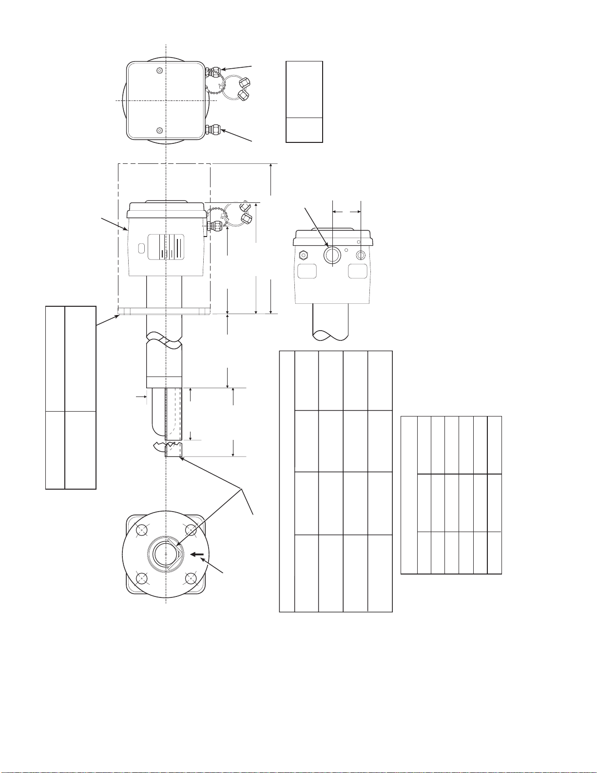
TO AMBIENT
REF AIR
CAL GAS
1/4 IN. TUBE
ANSI
ELEC
CONN
6 MM TUBE
6 MM TUBE
DIN
JIS
1/2"
CONDUIT
27270009
1.88 (48)
FURNISHED IN - XIT
ADAPTER & ACCESSORY
0.062 THK GASKET
INSULATE IF EXPOSED
WEATHER CONDITIONS
4512C34
4512C35
4512C36
3535B18H02
3635B48H01
3535B45H01
ANSI
JIS
DIN
2.27 (58)
DIA MAX
ROSEMOUNT
3.80 (96.5)
ADD TO DIM "A"
FOR PROBE
WITH CERAMIC
5.85 (148.6)DIM "A"
WITH STANDARD
DIFFUSER
4.90 (124.5)
7.58 (192)
SNUBBER
DIFFUSER
ADD TO DIM "A" FOR
DIFFUSER AND FLAME
PROBE WITH CERAMIC
DIM "B" REMOVAL ENVELOPE
ARRESTOR
GAS
CAL
JIS
6.10
4512C18H01
DIN
7.28
4512C19H01
ANSI
6.00
4512C17H01
(155)
(185)
(153)
0.59
0.71
0.75
AIR
REF
(15)
(18)
(20)
AT THE BOTTOM
BOTTOM VIEW
INSTALL WITH CONNECTIONS
5.12
(130)
5.71
(145)
4.75
(121)
THESE FLAT FACED FLANGES ARE MANUFACTURED
DIMENSIONS ARE IN INCHES WITH MILLIMETERS IN
TO ANSI, DIN, AND JIS BOLT PATTERNS AND ARE NOT
PARENTHESES.
2.
NOTES: 1.
DIM "B"
27.3 (694)
45.3 (1151)
16 (406)
34 (864)
DIM "A"
PRESSURE RATED.
81.3 (2065)6FT
70 (1778)
117.3 (2980)
153.3 (3894)
142 (3607)
106 (2692)
TABLE I MOUNTING FLANGE
FLANGE
DIA.
HOLE
PROCESS FLOW MUST
BE IN THIS DIRECTION
WITH RESPECT TO
DEFLECTOR 3534848G01
Figure 2-1. Probe Installation (Sh eet 1 of 5)
IB-106-300N H
2-2
DIA.
(4) HOLES
EQ SP ON BC
TABLE II INSTALLATION/REMOVAL
18 IN.
PROBE
3FT
9FT
12 FT

TABLE IV. FLANGE SIZE
7.50
BOLT
CIRCLE
0.75
(8) HOLES
DIAMETER
FLANGE
9.00 (153)
DIAMETER
*
ANSI
7.48
0.75
9.25 (235)
*
JIS
7.48
0.945
9.25 (235)
*
DIN
DIN, AND JIS BOLT PATTERNS AND ARE
* FLANGES ARE MANUFACTURED TO ANSI,
FLAT FACED. THESE FLANGES ARE NOT
PRESSURE RATED.
5.7
(145)
14.5
(369)
DIM "D" REMOVAL ENVELOPE
7.00
(178)
SEE TABLE IV
FOR FLANGE
SIZES
REF AIR AND
CAL GAS
CONNECTOR
ELECTRICAL
CONNECTOR
CAL GAS LINES
CHECK VALVE FOR
INSULATE IF
EXPOSED TO
AMBIENT WEATHER
27270010
CONDITIONS
31.1
(790)
45.3
(1151)
DIM "D" DIM "E"
27
(686)
DIM "C"
NOMINAL MEASUREMENTS
TABLE III. REMOVAL / INSTALLATION
3FT
67.1
81.3
63
6FT
(1704)
(2065)
(1600)
103.1
(2619)
117.3
(2980)
99
(2515)
9FT
139.1
(3533)
153.3
(3894)
(P/N 3535B58G04 - JIS)
135
12 FT
(3429)
DIM "C"
0.06 THK GASKET FURNISHED
DIM "E" (WITH FLAME ARRESTOR)
(P/N 3535B58G06 - DIN)
(P/N 3535B58G02 - ANSI)
IN HARDWARE PACKAGE
Figure 2-1. Probe Installation (Sh eet 2 of 5)
3.6
NOMINAL
(P/N 4843B38G02)
SNUBBER DIFFUSION/
DUST SEAL ASSEMBLY
DIMENSIONS ARE IN INCHES WITH
MILLIMETERS IN PARENTHESES.
NOTE:
IB-106-300N H
2-3
16860021
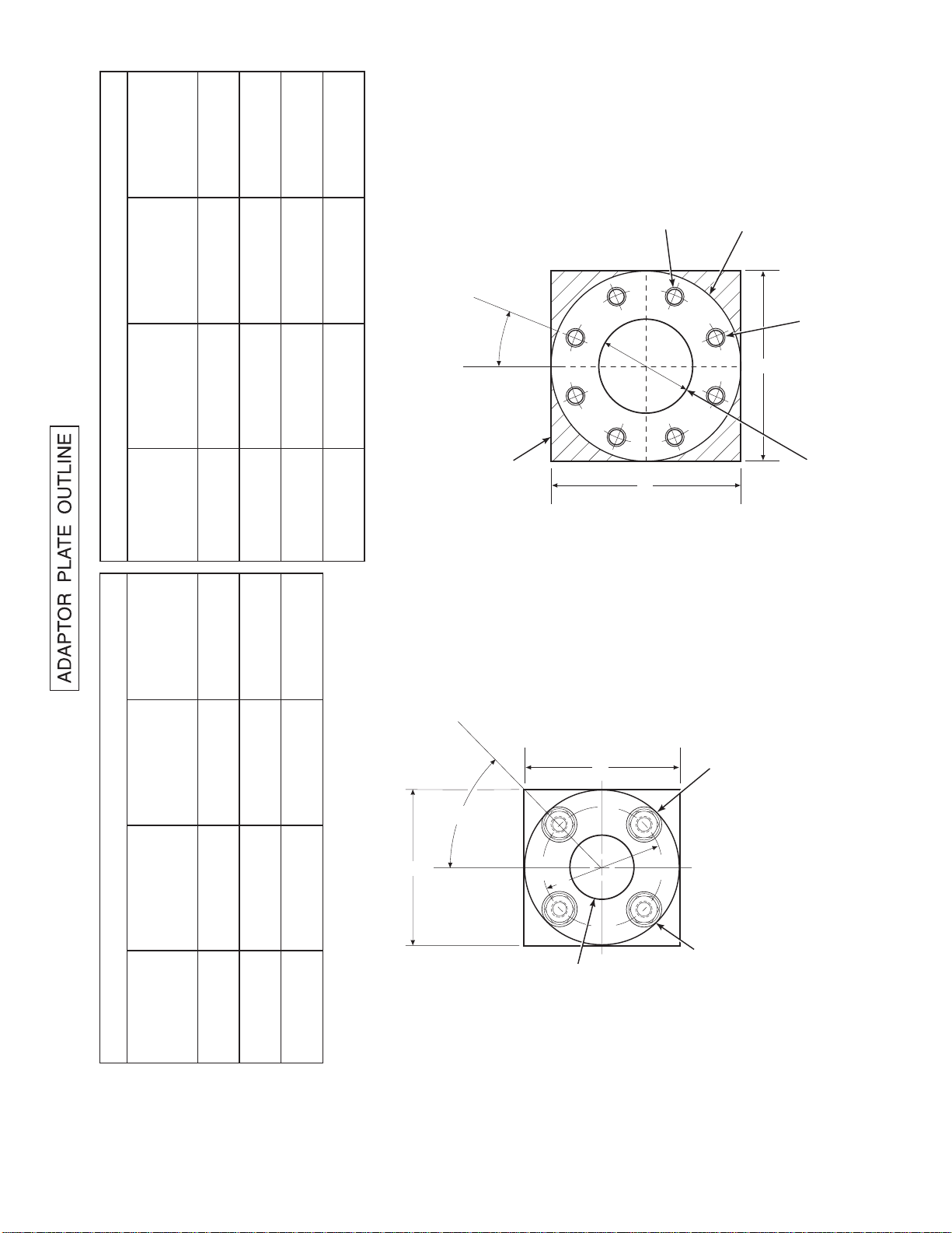
TABLE VI. ADAPTOR PLATE DIMENSIONS FOR ABRASIVE SHIELD
JIS
(P/N 3535B58G04)
DIN
(P/N 3535B58G06)
ANSI
(P/N 3535B58G02)
IN.
(mm)
"A"
DIMENSIONS
9.25
(235)
9.25
(235)
9.00
(229)
4.92
3.94
4.75
"B"
(125)
(100)
(121)
DIA
(M-20 x 2.5)
(M-16 x 2)
0.625-11
"C"
THREAD
(200)
7.894
7.48
(190)
7.50
(191)
"D"
DIA
ATTACHING HARDWARE.
NOTE: PART NUMBERS FOR ADAPTOR PLATES INCLUDE
8 THREADED HOLES
EQUALLY SPACED ON
D DIA B.C.
o
ABRASIVE SHIELD
FLANGE O.D.
C
22.5
A
B
A
OUTSIDE WALL SURFACE.
CROSSHATCHED AREA IN 4
CORNERS MAY BE USED TO
FIELD BOLTING OF PLATE TO
TABLE V. ADAPTOR PLATE DIMENSIONS FOR PROBE
JIS
(P/N 4512C35G01)
DIN
(P/N 4512C36G01)
ANSI
(P/N 4512C34G01)
IN.
(mm)
DIMENSIONS
6.50
(165)
7.5
(191)
6.00
(153)
"A"
(M-12 x 1.75)
(M-16 x 2)
0.625-11
"B"
THREAD
(130)
5.118
(145)
5.708
4.75
(121)
"C"
DIA
ATTACHING HARDWARE.
NOTE: PART NUMBERS FOR ADAPTOR PLATES INCLUDE
PROVIDE ADDITIONAL HOLES FOR
AND 12 FT ABRASIVE SHIELD
ADAPTOR PLATE FOR 3, 6, 9,
INSTALLATIONS. SEE SHEET 2.
4 STUDS,
LOCKWASHERS AND
NUTS EQUALLY
SPACED ON
A
o
C DIA B.C.
45
A
C
B
2.500 DIA
ADAPTOR PLATE FOR
STD WORLD CLASS 3000
PROBE INSTALLATION.
SEE SHEET 1.
Figure 2-1. Probe Installation (Sh eet 3 of 5)
IB-106-300N H
2-4

INSTALLATION FOR METAL
WALL STACK OR DUCT
CONSTRUCTION
INSTALLATION FOR MASONRY
WALL STACK CONSTRUCTION
MTG HOLES
SHOWN ROTATED
o
45
OUT OF
TRUE POSITION
WELD OR BOLT ADAPTOR
PLATE TO METAL WALL
OF STACK OR DUCT.
JOINT MUST BE AIR TIGHT.
0.50 [13]
3.75 [95]
MIN DIA HOLE
IN WALL
STACK OR DUCT
METAL WALL
0.50 [13]
BOLT ADAPTOR
PLATE TO OUTSIDE
WALL SURFACE
FIELD WELD
PIPE TO
ADAPTOR PLATE
MTG HOLES
SHOWN ROTATED
o
45
TRUE POSITION
OUT OF
JOINT MUST
BE AIRTIGHT
OUTSIDE WALL
SURFACE
NOTE: ALL MASONRY STACK WORK AND JOINTS EXCEPT
ADAPTOR PLATE NOT FURNISHED BY ROSEMOUNT.
4.50 [114]
O.D. REF
PIPE 4.00 SCHED 40
PIPE SLEEVE (NOT
BY ROSEMOUNT)
LENGTH BY CUSTOMER
MASONRY
STACK WALL
WELD OR BOLT ADAPTOR
PLATE TO METAL WALL
OF STACK OR DUCT.
JOINT MUST BE AIR TIGHT.
2.50 [63.5]
MIN DIA HOLE
IN WALL
STACK OR DUCT
METAL WALL
BOLT ADAPTOR
PLATE TO OUTSIDE
WALL SURFACE
JOINT MUST
BE AIRTIGHT
OUTSIDE WALL
SURFACE
NOTE: DIMENSIONS IN INCHES WITH
MILLIMETERS IN PARENTHESES.
Figure 2-1. Probe Installation (Sh eet 4 of 5)
FIELD WELD
PIPE TO
ADAPTOR PLATE
3.50 [89]
O.D. REF
PIPE 3.00 SCHED 40
PIPE SLEEVE (NOT
BY ROSEMOUNT)
LENGTH BY CUSTOMER
MASONRY
STACK WALL
624038
IB-106-300N H
2-5

o
60 MAX.
BRACE BARS
(NOT BY ROSEMOUNT)
2.00
(51)
1.00
(25)
NOTE: DIMENSIONS IN INCHES WITH
MILLIMETERS IN PARETHESES.
VERTICAL BRACE CLAMP ASSY.
HORIZONTAL BRACE CLAMP ASSY.
(BOTH BRACE CLAMP ASSEMBLIES ARE THE SAME.
INSTALLATION AND LOCATION OF CLAMP ASSEMBLIES
AND BRACE BARS TO BE DONE IN FIELD.)
BY ROSEMOUNT
}
o
30 MIN.
4.12
(105)
4.12
(105)
2 HOLES - 0.625
(16) DIA. FOR
0.50 (12) DIA.
BOLT
0.375
(10)
1.00
(25) MAX.
NOTE: BRACING IS FOR VERTICAL AND HORIZONTAL PROBE INSTALLATION.
EXTERNAL BRACING REQUIRED FOR 9 FT AND 12 FT
(2.75 M AND 3.66 M) PROBES AS SHOWN ABOVE.
5.62
(143)
5.62
(143)
36.00 (914)
ABRASIVE SHIELD
Figure 2-1. Probe Installation (Sh eet 5 of 5)
27270008
4. If using the optional ceramic diffusor element,
the vee deflector must be correctly oriented.
Before inserting the probe, check the
direction of flow of the gas in the duct. Orient
the vee deflector on the probe so that the apex
points upstream toward the flow (Figure 2-2).
This may be done by loosening the setscrews,
and rotating the vee deflector to the desired
position. Retighten the setscrews.
5. In horizontal installations, the probe junction
box should be oriented so that the system
cable drops vertically from the probe junction
box. In a vertical installation, the system cable
can be oriented in any direction.
6. If the system has an abrasive shield, check the
dust seal packings. The joints in the two
packings must be staggered 180°. Also, make
sure that the packings are in the hub grooves
IB-106-300N H
as the probe slides into the 15° fo rcing cone
in the abrasive shield.
NOTE
If process temperatures will exceed 392°F
(200°C), use anti-seize compound on stud
threads to ease future removal of probe.
7. Insert probe through the opening in the
mounting flange and bolt the unit to the
flange. When probe lengths selected are 9 or
12 ft (2.74 or 3.66 m), special brackets are
supplied to provide additional support for the
probe inside the flue or stack. See Figure 2-1,
sheet 5.
NOTE
Probe Installation
To maintain CE compliance, ensure there is
a good connection between the chassis of the
probe and earth.
2-6

APEX
6240
TO PROBE HEAD
REF AIR SET
263C152G01
1 FLOWMETER 0.2-2.0 SCFH 771B635H02
2 2" PRESSURE GAGE 0-15 PSIG 275431-006
3 COMBINATION FILTER-REG. 0-30 PSIG 4505C21G01
NOTE: DIMENSIONS ARE IN INCHES WITH
MILLIMETERS IN PARENTHESES.
1
2
3
4.81 (122.17)
FLOW SET
POINT KNOB
0.125-27 NPT FEMALE
OUTLET CONNECTION
1.19
(30.22)
10.0 REF
(254)
DRAIN VALVE
3.12 (79.25) MAX
8.50 MAX
(215.90)
2.0
(50.80)
2 MOUNTING HOLES
3.19 (81.03) LG
THROUGH BODY FOR
0.312 (7.92) DIA BOLTS
1.50
(38.10)
2.250 (57.15)
SCHEMATIC HOOKUP FOR REFERENCE AIR SUPPLY ON OXYGEN ANALYZER PROBE HEAD.
OUTLET
0.25-18 NPT FEMALE
INLET CONNECTION
COMPRESSED AIR SUPPLY
10-225 PSIG MAX PRESSURE
27270003
0.250 OR 6 MM OD TUBING
(SUPPLIED BY CUSTOMER)
0.250 OR 6 MM OD
TUBE COMPRESSION
FITTING (SUPPLIED BY WECO)
FILTER
GAS FLOW
DIRECTION
VEE
DEFLECTOR
DIFFUSION
ELEMENT
SETSCREW
c. Reference Air Package. After the oxygen
analyzing (probe) unit is installed, connect the
reference air set to the probe junction box. The
reference air set should be installed in accordance
with Fig u re 2- 3.
d. Service Required.
1. Power input: 100, 115 or 220 Vac single
phase, 50 to 60 Hz, 3 amp minimum. (See
label.)
Figure 2-2. Orienting the Optional Vee Defl ector
VEE
DEFLECTOR
2. Compressed air: 10 psig (68.95 kPa)
minimum, 225 psig (1551.38 kPa) maximum
at 2 scfh (56.6 L/hr) maximum; supplied by
one of the following (less than 40 parts-permillion total hydrocarbons). Regulator outlet
pressure should be se t at 5 ps i (35 k Pa).
17
(a) Instrument air - clean, dry.
Figure 2-3. Air Set, Plant Air Connection
IB-106-300N H
2-7

(b) Bottled standard air with step-down
5.76 (146.3)
9.00 (228.6)
1.25
(31.75)
21190002
6.0
(152.4)
DESIGN DIMENSIONS ARE IN INCHES
WITH MILLIMETERS IN PARENTHESES.
NOTE:
8.00 (203.2)
11.24 (285.5)
0.31
(7.9)
13.24
(336.3)
15.00
(381.0)
16.00
(406.4)
2.00
(50.8)
1.62
(41.1)
2.25
(57.15)
0.867
(22.00)
11.5 (292.1) MINIMUM DOOR
SWING CLEARANCE
3.36
(85.3)
regulator.
(c) Bottled compressed gas mixture
(20.95% oxygen in n i trogen).
(d) Other equivalent clean, dry, oil-free air
supply.
2-2. INTELLIGENT FIELD TRANSMITTER (IFT)
INSTALLATION.
a. Mechanical Installation. The outline drawing of
the IFT module in Figure 2-4 shows mounting
centers and clearances. The NEMA 4X enclosure
is designed to be mounted on a wall or bulkhead.
The IFT should be installed no more than
1200 feet (364 m) from the optional HPS or
150 feet (45 m) from the probe if HPS is not
installed in the system.
b. Electrical Connections.
To meet the Safety Requirements of IEC
1010 (EC requirement), and ensure safe
operation of this equipment, connection to
the main electrical power supply must be
made through a circuit breaker (min 10A)
which will disconnect all current carrying
conductors during a fault situation. This
circuit breaker should also include a
mechanically operated isolating switch. If
not, then another external means of
disconnecting the supply from the equipment
should be located close by. Circuit breakers
or switches must comply with a recognized
standard such as IE C 947.
NOTE
Refer to Figure 2-7 for fuse locations and
specifications.
1. The IFT can be configured for 100, 120, 220,
or 240 line voltages. For 120 Vac usage,
install JM8, JM7, and JM1 on the power
supply board. For 220 Vac usage, install
jumpers JM6, JM5, JM2 (refer to Figures 2-5
and 2-7).
2. For installations where the cable run is less
than 150 feet (45 m), the IFT can be
configured to connect directly to a probe. An
optional HPS is available for cable runs o ver
Figure 2-4. Outline of Intelligent Field Transmitter
150 feet (45 m). The electrical connections
for a non-HPS equipped system should be
made as described in the electrical installation
diagram, Figure 2-8. Refer to Figure 2-14 for
connections for an HPS equipped system.
Do not install jumper JM6 on the
microprocessor board, or JM1 on the
interconnect board, if an HPS is installed in
the system. This will result in system failure.
3. The IFT must have JM6 on the
microprocessor board (Figures 2-9 and 2-10)
and JM1 on the interconnect board (Figures
2-11 and 2-12) installed if an HPS is not
installed in the system.
IB-106-300N H
2-8

4. If an MPS is not used in the system, wire
jumper between CAL RET and NO GAS
must be installed on the interconnect board.
Remove wire jumper if MPS is installed in the
system. Refer to Figure 2-8, note 6.
5. The power cable should comply with the
safety regulations in the user's country and
should not be sm al l er th an 16 gauge, 3 amp.
JUMPER
CONFIGURATION
LINE VOLTAGE
SELECTION
100 V.A.C.
120 V.A.C.
220 V.A.C.
240 V.A.C.
JUMPER
(INSTALL)
JM3, JM7, JM2
JM8, JM7, JM1
JM6, JM5, JM2
JM6, JM5, JM1
6. Before supplying power to the IFT, verify that
the jumpers have been properly set in the IFT
(Figures 2-5, 2-9, an d 2-11).
7. Terminal strip J5 on the power supply board
is used for supplying the IFT with power.
Terminal strip J6 on the power supply board
is used to supply the probe heater with power
if an HPS is not used (Figure 2-7).
ALWAYS DISCONNECT LINE VOLTAGE
FROM INTELLIGENT FIELD TRANSMITTER
BEFORE CHANGING JUMPERS.
PROBE HEATER
VOLTAGE SELECTION
WORLD CLASS PROBE (44V)
218 PROBE (115V)
WORLD CLASS "DIRECT
REPLACEMENT" PROBE (115V)
JUMPER
(INSTALL)
JM10
JM9
JM9
21190012
If incorrect heater voltage is selected, damage to the probe may occur. For HPS voltage selection jumper,
refer to Figure 2-15. Always update the relevant labeling to reflect the set voltage.
Figure 2-5. Power Supply Board Jumper Configuration
NOTE
General Wiring Recommendations
To maintain CE compliance and ensure proper EMC performance, all signal wires to the Interconnect
Board, with the exception of the probe cable, should be looped through the ferrite beads provided as
shown in Figure 2-6 (P/N 1L04253H01). Signal wires may be grouped together and looped through before
exiting the enclosure. Ferrite beads should be placed as close as possible to the exit point. Ferrite beads
are provided for European Common Market applications only.
Figure 2-6. Signal Wire Routing
IB-106-300N H
2-9
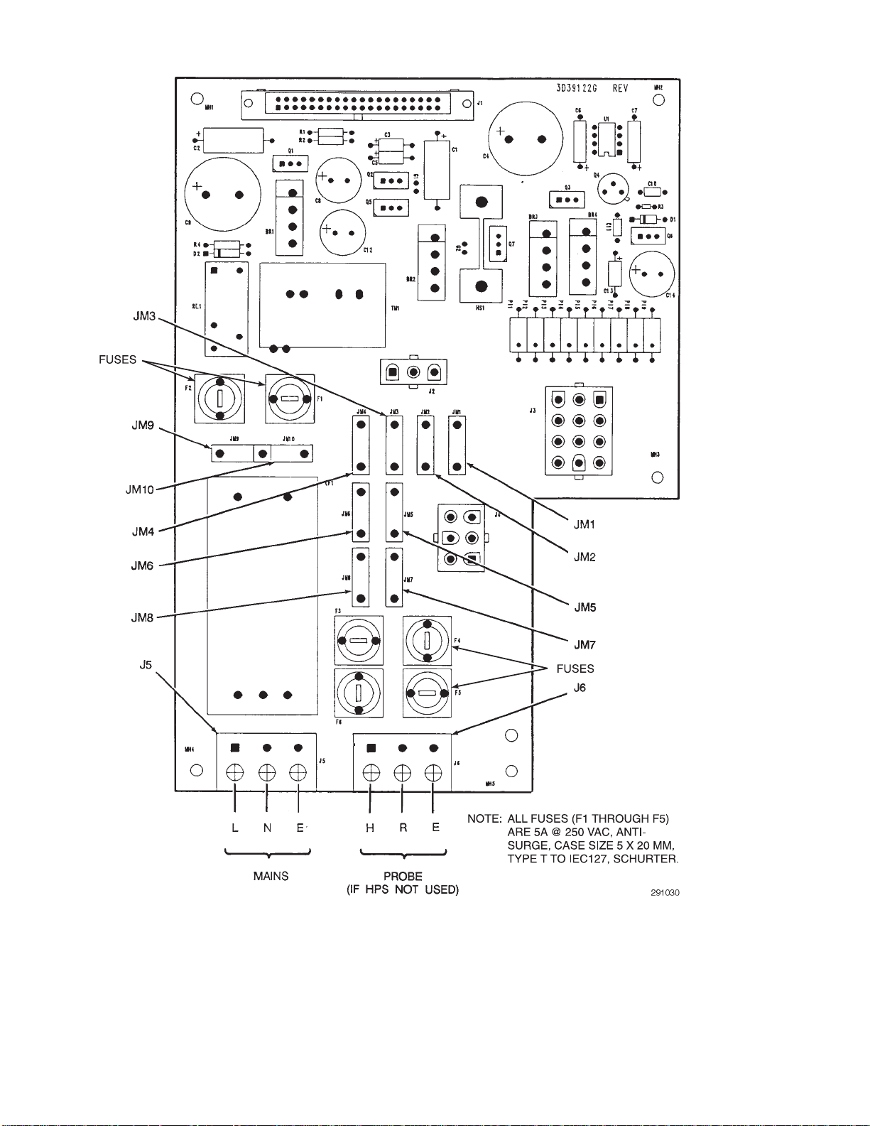
Figure 2-7. IFT Power Supply Board Jumpers
IB-106-300N H
2-10

PROBE JUNCTION
BOX WIRING
GN CELL -VE
OR CELL +VE
YE CHROMEL
RD ALUMEL
GN
BK
123456 78
BLPROBE MV -
YE
RD
OR
GNE
WH
R
HEATER
CURRENT/VOLTAGE
SELECTOR SWITCH
3D39513G
MICROPROCESSOR
BOARD
}
BK
J1
BK
H
3D39122G REV
POWER SUPPLYBOARD
ALWAYS DISCONNECT LINE VOLTAGE
FROM INTELLIGENT FIELD TRANSMITTER
BEFORE CHANGING JUMPERS.
JM7
I
V
JM6
PROBE MV +
PROBE TC +
PROBE TC -
WORLD CLASS
PROBE
NOTES:
STACK TC WIRING AS REQUIRED.
SPECIAL PROBE CABLE BETWEEN PROBE
AND IFT BY ROSEMOUNT.
INSTALL JM1 ON INTERCONNECT BOARD.
INSTALL JM6 ON MICROPROCESSOR
BOARD.
IF STACK TEMPERATURE NOT USED.
IF MPS 3000 NOT USED.
1 RELAY PER PROBE AVAILABLE FOR
CALIBRATION STATUS INDICATION. (48 V
max, 100 mA max)
CURRENT/VOLTAGE SELECTOR SWITCH
MUST BE SELECTED TO CURRENT (I) FOR
HART COMMUNICATIONS APPLICATIONS.
JUMPER JM7 INFORMATION APPEARS IN
FIGURE 2-9.
LINE
VOLTAGE
SECTION
100 V.A.C.
120 V.A.C.
220 V.A.C.
240 V.A.C.
JUMPER CONFIGURATION
JUMPER
(INSTALL)
JM3, JM7, JM2
JM8, JM7, JM1
JM6, JM5, JM2
JM6, JM5, JM1
PROBE HEATER
VOLTAGE SECTION
WORLD CLASS PROBE
218 PROBE
WORLD CLASS "DIRECT
REPLACEMENT" PROBE
JUMPER
(INSTALL)
JM10
JM9
JM9
J2 J3 J4
3D39120G REV
INTERCONNECT BOARD
J1
J5
CAL RET
J5 J6
L
H
EN
LINE
VOLTAGE
BK
WH
GN
PU
OR
BL
YE
RD
INTELLIGENT FIELD
TRANSMITTER IFT 3000
ER
PROBE 1
LINE OUT LINE IN
J10
L
N
HI GAS
IN CAL
CAL RET
NO GAS
LOW GAS
NO GAS
LO GAS
HI GAS
IN GAS
SHIELD
PROBE 2 PROBE 3 PROBE 4
IN CAL
HI GAS
NO GAS
CAL RET
LOW GAS
NC C NO NC C NO NC C NO NC C NO
J11
PROBE 1
PROBE 2 PROBE 3 PROBE 4
MPS 3000 MULTIPROBE CALIBRATION GAS SEQUENCER (OPTIONAL)
MPS TERMINATION BOARD
J6
J7
SHIELD
STACK TC STACK TC +
J8 J9
SHIELD
PROBE TC -
RD
YE
PROBE TC +
SHIELD
BL
OR
5 CONDUCTOR SHIELDED CABLE
PER PROBE #16 AWG BY CUSTOMER
IN CAL
HI GAS
CAL RET
PROBE 1
SOLENOID
J13 J14 J15 J16 J17 J18
PROBE MV
PROBE
NO GAS
LOW GAS
PROBE 2
SOLENOID
-
MV+
HI GAS
PROBE 3
SOLENOID
IN CAL
PROBE 4
SOLENOID
NO GAS
CAL RET
HIGH GAS
SOLENOID
LOW GAS
JM1
LOW GAS
SOLENOID
L
N
SWITCH
PRESSURE
J12
L
LINE
E
VOLTAGE
N
27270011
Figure 2-8. Wiring Layout for IFT 3000 Sys tem without HPS
IB-106-300N H
2-11

OUTPUT JUMPER
HPS
Probe (No HPS)
Remove JM6
Install JM6
ANALOG OUTPUT
(Condition during
microcontroller failure) JUMPER
Output = zero
Output = maximum
Install JM7
Remove JM7
analog output is typically sent to recording
equipment such as chart recorders. Relay
outputs are typically sent to annunciators.
3. Relays K1 and K2 are user configurable from
the probe SETUP sub-menu (Table 3-5).
Typically these are used to indicate O
values
2
above or below specified tolerances . OK relay
is energized when unit is functioning
properly.
4. All wiring must conform to local and national
codes.
(See Figure 2-10 for jumper locations .)
Figure 2-9. Microprocessor Board Jump er Con figu ration
c. Analog Output and Relay Output Connections.
1. The microprocessor board has a selector for
voltage or current operations. Figure 2-10
shows switch orientation. In voltage mode,
output is 0-10 V. In the current mode, the
output can be configured from the SETUP
menu to be 0- 20 mA or 4-20 mA.
2. The analog output and relay outputs are
programmed by the user as needed. The
5. Connect the analog output and relay outputs
as shown i n Fi g u re 2-12.
2-3. HEATER POWER SUPPLY INSTALLATION.
a. Mechanical Installation.
The outline drawing of
the heater power supply enclosure in Figure 2-13
shows mounting centers and clearances. The
NEMA 4X enclosure is designed to be mounted on
a wall or bulkhead. The heater power supply
should be installed no further than 150 feet (45 m)
from the probe. The heater power supply must be
located in a location free from significant ambient
temperature changes and electrical noise. Ambient
temperature must be between -20° and 140°F (-30°
and 60°C).
IB-106-300N H
2-12

Figure 2-10. IFT Microprocessor Board
IB-106-300N H
2-13

OUTPUT JUMPER
2
2
1
1
3
3
4
4
5
5
6
6
7
7
8
8
9
9
10
10
11
11
12
12
13
13
14
14
15
15
16
16
17
17
18
18
19
19
20
20
21
21
22
22
23
23
24
24
OK-COM
OK-NO
K1-COM
K1-NO
K2-COM
K2-NO
ANOUT
-
ANOUT+
STACK T/C
STACK T/C
PROBE T/C
PROBE T/C
PROBE MV
-
PROBE MV+
OK-NC
K1-NC
K2-NC
CALINIT-2
CAL INIT-1
CALRET
NOGAS
LOGAS
HIGAS
INCAL
RELAY
-
RELAY+
AD590
-
AD590+
TRIAC
-
TRIAC+
JM1
(UNDER
SHIELD)
NOTES:
DENOTES SHIELD CONNECTION.
OK RELAY IS ENERGIZED WHEN
UNIT IS FUNCTIONING PROPERLY.
16860010
HPS
Probe (No HPS)
Remove JM1
Install JM1
Figure 2-11. Interconnect Board Jumper Configuration
Figure 2-12. IFT Interconnect Board Output Connections
IB-106-300N H
2-14

3.25
(82.6)
NOTE: DIMENSIONS IN INCHES
WITH MILLIMETERS IN PARENTHESES.
7.00
(177.8)
3.63
(92.2)
(NON-HAZARDOUS)
NEMA 4X
10.39
(264)
0.31
(7.9)
6.00
#0.31
(152.4)
(124)
6.75
(171.5)
4.88
4.00
(101.6)
(215.9)
8.50
b. Electrical Connections.
1. Electrical connections should be made as
described in the electrical installation
diagram, Figure 2-14. The wiring terminals
are divided into two layers; the bottom
(FROM PROBE) terminals should be
connected first, the top (FROM
ELECTRONICS) terminals should be
connected last (Figure 2-15). Each terminal
strip has a protective cover which must be
removed when making connections. To
remove the terminal covers, remove two
slotted screws holding cover in place. Always
reinstall terminal covers after making
connections. All wiring must conform to local
and national codes.
0.13" (3.3) THK U. L. APPROVED
GASKET
4.38
1.81
(46)
11.00
(279.4)
8.00
(203.2)
#10-32 UNF 2A
THREADED INSERT
(0.31 x 0.31 FROM CORNER OF PLATE)
(111.3)
Figure 2-13. Outline of Heater Power Supply
9.96
(253)
0.38
(9.7)
1.00 (25.4) MINIMUM CLEARANCE
4.72
(120)
CLASS 1, DIVISION 1, GROUP B ENCLOSURE
FOR REMOVING COVER
9.17
(233)
2. Power Input: 120, 220 or 240 Vac. For
120 Vac usage, install jumpers JM4 and JM1.
For 220 or 240 Vac usage, install jumper JM5
(see label, Figure 2-16).
NOTE
For 100 Vac usage, the heater power supply
is factory-supplied with a different transformer. When using the HPS with 100 Vac
transformer, instal l ju mpers JM1 and JM4.
3. The power cable should comply with safety
regulations in the user's country and should
not be smaller th an 16 g auge, 3 amp.
8.50
(215.9)
6.18
(156.9)
0.56 (14)
DIA (2)
MOUNTING
HOLES
686029
NOTE
Refer to Figure 2-17 for fuse locations and
specifications.
IB-106-300N H
2-15

Figure 2-14. Wiring Layout for Com p le te I FT 3000 Sys tem with HPS (Sheet 1 of 2)
IB-106-300N H
2-16

C
URRENT/VOLTAGE
SELECTOR SWITCH
LINE
VOLTAGE
SECTION
100 V.A.C.
120 V.A.C.
200 V.A.C.
220 V.A.C.
240 V.A.C.
JUMPER
(INSTALL)
JM3, JM7, JM2
JM8, JM7, JM1
JM4, JM5, JM2
JM6, JM5, JM2
JM6, JM5, JM1
J5 J6
L
EN
LINE
VOLTAGE
J1
POWER SUPPLYBOARD
ALWAYS DISCONNECT LINE VOLTAGE
FROM INTELLIGENT FIELD TRANSMITTER
BEFORE CHANGING JUMPERS.
JUMPER CONFIGURATION
PROBE HEATER
VOLTAGE SECTION
NOT USED REMOVE
NOT USED
3D39122G REV
(INSTALL)
JUMPER
JM9, JM10
3D39513G
MICROPROCESSOR
BOARD
CAL RET
NO GAS
LO GAS
HI GAS
IN CAL
SHIELD
RELAY –
RELAY +
SHIELD
AD590 –
AD590 +
SHIELD
TRIAC –
TRIAC +
J2 J3
J4
J5 J6 J7 J8 J9
SHIELD
STACK TC –
STACK TC +
SHIELD
PROBE TC –
PROBE TC +
SHIELD
PROBE MV –
PROBE MV +
J1
3D39120G REV
INTERCONNECT BOARD
JM7
I
V
JM6
JM1
A
B
INTELLIGENT FIELD
TRANSMITTER IFT 3000
PROBE 1
LINE OUT LINE IN
L
IN CAL
HI GAS
NO GAS
CAL RET
J10
N
NC C NO NC C NO NC C NO NC C NO
J11
PROBE 1
PROBE 2 PROBE 3 PROBE 4
PROBE 2 PROBE 3 PROBE 4
IN CAL
HI GAS
LOW GAS
CAL RET
5 CONDUCTOR SHIELDED CABLE
PER PROBE #16 AWG BY CUSTOMER
NO GAS
LOW GAS
IN CAL
HI GAS
NO GAS
CAL RET
PROBE 2
PROBE 1
SOLENOID
J13 J14 J15 J16 J17 J18
LOW GAS
SOLENOID
PROBE 3
HI GAS
SOLENOID
IN CAL
PROBE 4
CAL RET
SOLENOID
HIGH GAS
NO GAS
SOLENOID
LOW GAS
LOW GAS
SOLENOID
L
N
SWITCH
PRESSURE
J12
L
E
N
LINE
VOLTAGE
MPS TERMINATION BOARD
MPS 3000 MULTIPROBE CALIBRATION GAS SEQUENCER (OPTIONAL)
27270012
Figure 2-14. Wiring Layout for Com p le te I FT 3000 Sys tem with HPS (Sheet 2 of 2)
IB-106-300N H
2-17

Figure 2-15. Heater Power Supply Wiring Connections
IB-106-300N H
2-18

1
0310
2
NOTES:
1
100 V.A.C. OPERATION REQUIRES TRANSFORMER PART
NUMBER 1M02961G02.
2
REFER TO TABLE 3-5 FOR PROPER SET POINT SELECTION.
Figure 2-16. Jumper Selecti on L ab el
NOTE
Before supplying power to the hea ter power
supply, verify that jumpers JM3, JM6 are
removed and JM7 is installed. If relay wire
(Figure 2-14, note 1) is installed, JM2 must
be removed from HPS Mother Board (Figure
2-17).
4. Before supplying power to the heater power
supply, verify that the jumpers on the mother
board, Figure 2-17, are properly configured.
Jumpers JM3 and JM6 should be removed
and JM7 should be inst all ed.
Additionally, make sure that the proper
jumper for your line voltage is installed,
Figure 2-16. If relay wire (Figure 2-14, note
1) is not installed, JM 2 should be installed
on the HPS Mother Board (Figure 2-17).
JM1
JM2
JM4
JM5
JM7
122
JM3
JM6
3D3 080G REV
21
NOTE
Refer to Figure 2-9 and 2-11 for proper IFT
jumper configuration. IFT microprocessor
and interconnect board jumper configurations must be set correctly in order for HPS
to work properly.
Figure 2-17. Jumpers on HPS Mother Board.
IB-106-300N H
2-19

2-4. MULTIPROBE CALIBRATION GAS SEQUEN-
HIGHCAL
GASIN
LOWCAL
GASIN
CALGAS
OUT
REFAIR
OUT
INSTR
AIR
REFAIR
OUT
REFAIR
OUT
REFAIR
OUT
CALGAS
OUT
CALGAS
OUT
CALGAS
OUT
PROBE1 PROBE2 PROBE3 PROBE4
0.84 (21.34)
27270013
1.96 (49.78)
4.21 (106.93)
3.09 (78.49)
5.25 (133.35)
5.54 (140.72)
14.00 (355.60) REF
12.00
(304.80)
12.00
(304.80)
10.00
(254.00)
NOTE: DIMENSIONS ARE IN INCHES
WITH MILLIMETERS IN
PARENTHESES.
CER INSTALLATION.
a. Mechanical Installation.
The outline drawing of
the MPS module in Figure 2-18 shows mounting
centers and clearances. The box is designed to be
mounted on a wall or bulkhead. The MPS module
should be installed no further than 300 feet (91 m)
piping distance from the probe, and no more than
1000 feet (303 m) cabling distance from the IFT.
Install the MPS module in a location where the
ambient temperature is between -20° and 160°F
(-30° and 71°C).
b. Gas Connections
. Figure 2-19 shows the bottom
of the MPS where the gas connections are made.
1/4 inch threaded fittings are used.
1. Connect the reference air supply to INSTR.
AIR IN. The air pressure regulator valve is set
at the factory to 20 psi (138 kPa). If the
reference air pressure should need readjustment, turn the knob on the top of the valve
until the desired pressure is obtained.
2. Connect the high O
calibration gas to HIGH
2
GAS. The calibration gas pressure should be
set at 20 psi (138 kPa).
Figure 2-18. MPS Module
IB-106-300N H
2-20

3. Connect the low O2 calibration gas to LOW
HIGH CAL
GAS IN
LOW CAL
GAS IN
CAL GAS
OUT
REF AIR
OUT
INSTR
AIR
REF AIR
OUT
REF AIR
OUT
REF AIR
OUT
CAL GAS
OUT
CAL GAS
OUT
CAL GAS
OUT
PROBE 1 PROBE 2 PROBE 3 PROBE4
LINE IN
SIGNAL IN
27270014
DRAIN
GAS. The calibration gas pressure should be
set at 20 psi (138 kPa).
system is being used, the additional probes and
electric packages would be wired similar to the
first probe.
4. Connect the REF AIR OUT to the reference
air fitting on the probe junction box.
5. Connect the CAL GAS OUT to the
calibration gas fitting on the probe junction
box.
6. If the MPS is configured for multiple probes
(up to four), repeat steps 4 and 5 for each
additional probe.
A check valve is required for each probe
connected to an MPS to prevent
condensation of flue gas in the calibration gas
lines. The check valve must be located
between the calibration fitting and the gas
line.
c. Electrical Connections.
Electrical connections
should be made as described in the electrical
installation diagram, Figure 2-20. All wiring must
conform to local and national codes. The electrical
connections will exist only between the electronics
package and the MPS to enable automatic and
semiautomatic calibration. If more than one probe
NOTE
Refer to Figure 2-20 for fuse locations and
specifications.
1. Run the line voltage through the bulkhead
fitting on the bottom of the MPS where
marked LINE IN, Figure 2-19. Connect the
line voltage as shown in Figure 2-20 to the
LINE IN terminal on the MPS termination
board located inside the unit. Tighten the cord
grips to provide strain relief.
2. The MPS can accommodate up to four
probes. The terminal strips on the MPS
termination board are marked PROBE 1,
PROBE 2, PROBE 3, and PROBE 4. Select
PROBE 1 if this is the first probe and
electronic package installed on the MPS.
3. Make the connections from the MPS to the
IFT as shown in Figure 2-20. Run wires from
the MPS Termination Board inside the unit
through the bulkhead fitting on the bottom o f
the unit where marked SIGNAL IN, Figure
2-19. After the connections are made, tighten
the cord grips to provide strain relief.
Figure 2-19. MPS Gas Connections
IB-106-300N H
2-21

INTERCONNECT
IFT
BOARD
CAL RET
NO GAS
LO GAS
HI GAS
IN CAL
MH1
J1
J2 J3 J4 J5 J6 J7 J8 J9
MH2
MH3
MH4
PROBE 1 PROBE 2 PROBE 3 PROBE 4
LINE OUT LINE IN
L
IN CAL
HI GAS
N
NO GAS
CAL RET
LOW GAS
IN CAL
HI GAS
NO GAS
CAL RET
LOW GAS
HI GAS
IN CAL
NO GAS
CAL RET
LOW GAS
HI GAS
IN CAL
NO GAS
CAL RET
LOW GAS
L
N
J10
NC C NO NC C NO NC C NO NC C NO
J11
PROBE 1
PROBE 2 PROBE 3 PROBE 4
J13 J14 J15 J16 J17 J18
J12
MPS TERMINATION BOARD
Figure 2-20. MPS Probe Wiring
L
E
N
LINE
VOLTAGE
686032
IB-106-300N H
2-22
NOTE
!
Upon completing installation, make sure that the probe is turned on and
operating prior to firing u p the combustion process. Damage can result from
having a cold probe exposed to the process gases.
During outages, and if possible, leave all probes running to prevent
condensation and premature aging from thermal cycling.
If the ducts will be washed down during outage, MAKE SURE to power down
the probes and remove them from the wash area.
IB-106-300N H
2-23/2-24

SECTION III. GENERAL USER INTERFACE (GUI) OPERATION
3-1. OVERVIEW.
power supply, and intelligent field transmitter have
been properly connected. It is important to check that
grounding and screening of terminations are correctly
made to prevent the introduction of ground loops. The
IFT is equipped with noise suppression circuitry on the
power supply and signal input lines. Proper grounding
at installation will ensure accuracy of function.
The following five languages are can be selected within
the IFT:
English Italian
French Spanish
German
Support the keypad with the free hand to
prevent bounce back of the IFT door.
a. Intelligent Field Transmitter (IFT). The
Intelligent Field Transmitter may be supplied with
either of two configurations. These are the blind
version and the deluxe ve rsion. The two versions
differ as follows:
Ensure that the oxygen analyzer, heater
NOTE
b. HART Communicator Interface Devices. The
HART communi cations protocol can in terf ace w ith
any of the above IFT versions. To interface a
HART communicator with an IFT, one of three
interface devices is required. The interface devices
are as follows:
1. Rosemount Model 275 Handheld Communicator. The handheld communicator requires
Device Descriptor (DD) software specific to
the World Class 3000 product. The DD
software will be supplied with many model
275 units, but can also be programmed into
existing units at most Fisher-Rosemount
service offices.
2. Personal Computer (PC). The use of a
personal computer requires Cornerstone
software with Module Library (ModLib)
specific to the World Clas s 3000 produ ct .
3. Selected Distributed Control Systems. The
use of distributed control systems requires
input/output (I/O) hardware and software
which permit HART communications.
1. Blind Version. The blind version has no
display and no keypad. With this version an
external HART communications device is
required.
2. Deluxe Version (GUI). The deluxe version
is also known as the General User Interface
(GUI) version. This IFT contains an LED
display, liquid crystal display panel, and an
eight-key pad from which the probe and
electronics can be configured, calibrated and
troubleshooted.
This section of the manual deals with operator controls
and displays available with the GUI equipped IFT.
Operating parameters are listed and instructions are
included for viewing and changing them.
Any procedures not associated with normal operation
are included in Section II, Installation, or Section V,
Troubleshooting.
IB-106-300N H
3-1
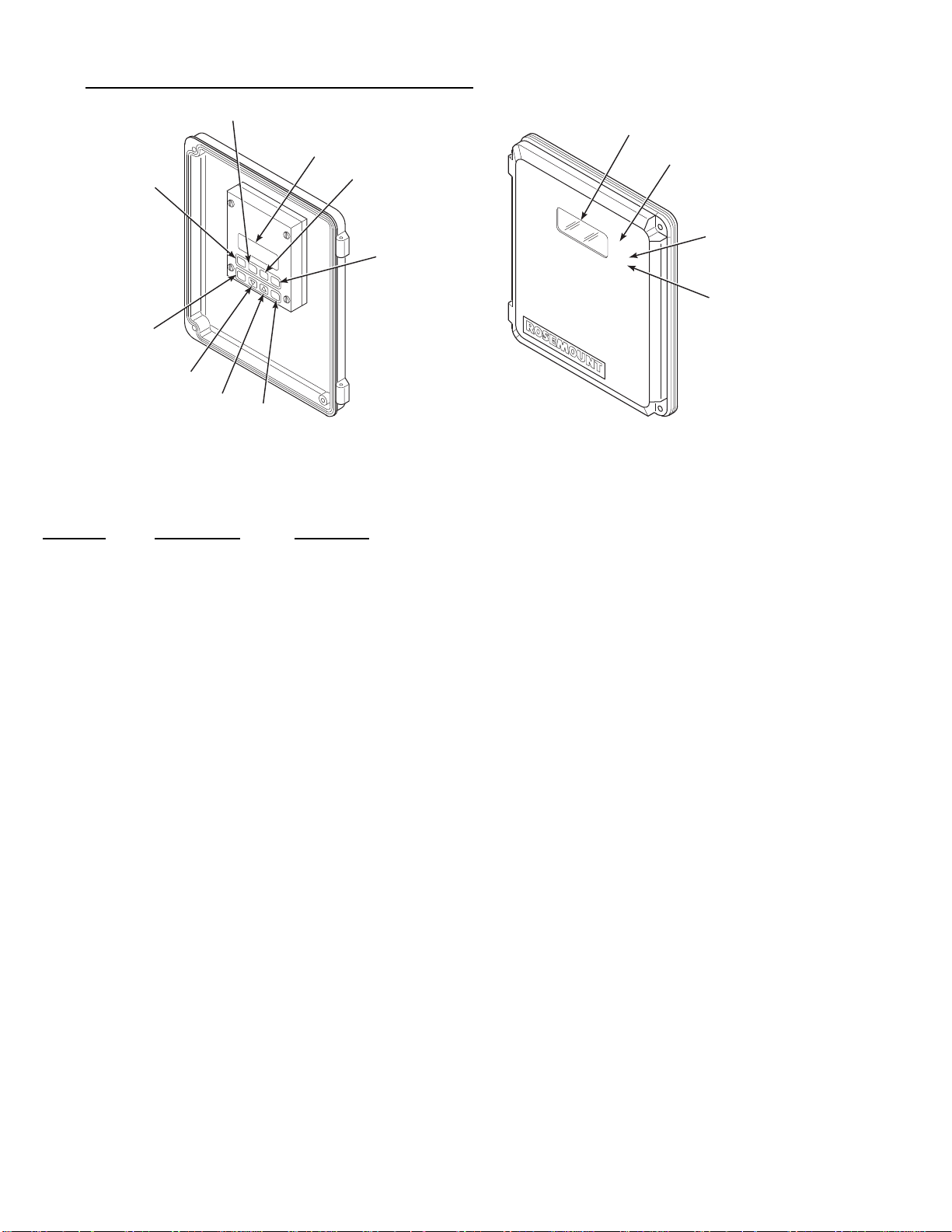
3-2. DELUXE VERSION IFT DISPLAYS AND CONTROLS.
3
(Figure 3-1)
3
1
2
HELP
DATA
CAL
ESC
SETUP
ENTER
6
7
8
9
INTERNAL VIEW
4
5
IFT COVER DOOR
NOTE:
SHOWN FOR
REFERENCE.
EXTERNAL VIEW
CAL
TGH
TGL
10
11
12
2119000
Figure 3-1. Deluxe Version IFT Disp lays an d Con trols
Fig. 3-1
Index No. Control/LED
Description
1 LCD Display Top line displays s ystem status, menu, and probe number.
2 HELP Context sensitive HELP is displayed when this key is pressed.
3 DATA DATA k ey is used to access DATA menu.
4 CAL CAL key u s ed to acces s CALIBRATE menu.
5 SETUP SETUP key used to access SETUP menu.
6 ESC The escape key is used to exit to a hi g h lev el menu or to abort a parameter change.
13
7
?
The decrease key is used to move the c urso r ( aste risk) when scro lling thro ugh lists or to
decrease a parameter value.
8
>
The increase key is used to move the curso r (a sterisk) when scro lling thro ugh lists or to
increase a parameter value.
9 ENTER The ENTER key is used to select a lower level menu, initiate calibration, or select a
parameter to change.
10 LED Display Indicates current O
or calibration gas value.
2
11 CAL Calibration in progress indicator light.
12 TGH High calibration gas indicator light. High calibration gas is being used in calibration
process.
13 TGL Low calibration gas indicator light. Low calibration gas is being used in calibration
process.
IB-106-300N H
3-2

Table 3-1. Sample HELP Messages.
MENU, SUB-MENU, HELP
OR PARAMETER NAME MESSAGE
PROBE DATA
CALIBRATE O2
SETUP
Press ENTER key to access DATA m en u.
The CAL menu is used to start calibration and view calibration.
The SETUP menu is us ed t o con f i g u re the IFT 3000.
3-3. HELP KEY. The HELP key will display explanatory
information about a menu, sub-menu, or parameter that
the asterisk is next to when pressed. The HELP key is
not available during calibration routines. Refer to Table
3-1 for sample HELP messages.
3-4. STATUS LINE. The top line of the LCD display (3,
Figure 3-1) is a status line that always displays system
status, menu name, and O
level. System status displays
2
will be displayed one at a time in priority sequence, as
follows:
a. Off - The probe has been turned off because the
IFT cannot control the heater temperature.
b. PrbEr - The probe is disconnected, cold, or leads
are reversed.
i. ResHi - Resistance is above the high lim it.
j. OK - System is functioning correctly.
3-5. QUICK REFERENCE CHART. The quick
reference chart ( Figure 3 -2) is d esigned to help you get
where you want to be in the menu system. The chart
shows all the available menu and sub-menu options for
the IFT. Follow the lines to determine which menu
choices to make. Moving down a level on the chart is
accomplished by the use of the ENTER key. To move
up a level on the chart, press the ESCA PE key.
Table 3-2. MAIN Menu.
MENU SELECTION DESCRIPTION
PROBE DATA
Refer to Table 3-3.
c. HtrEr - Heater error.
d. InCAL - Calibration in progress.
e. LowO2 - O2 value is below the low alarm limit.
f. HiO2 - O2 value is above the high alarm limit.
g. NoGas - Calibration gas pressure is low.
h. CalEr - Calibration error.
CALIBRATE O2
SETUP
Refer to Table 3-4.
Refer to Table 3-5.
3-6. MAIN MENU. When power is first applied to the
IFT, the MAIN menu (Table 3-2) is initially displayed.
It is from the MAIN menu that the PROBE DATA
(Table 3-3), CALIBRATE O2 (Table 3-4), and SETUP
(Table 3-5) menus can be access ed.
IB-106-300N H
3-3

3-7. PROBE DATA SUB-MENU. The PROBE DATA
sub-menu is a list of all the parameters of the system as
it is currently configured. To access the PROBE DATA
sub-menu, press the DATA key at any time. The
increase and decrease keys are used to scroll through
the list. The PROBE DATA sub-menu can be
Table 3-3. PROBE DATA Sub-Menu.
SUB-MENU
SELECTION PARAMETER DESCRIPTION
Process Data O2 __% O2
Efficiency __%
Stack Temp __DegC
Diagnostic Data
Temperature
Cell __DegC
Stack __DegC
Cold Junct __DegC
viewed but not changed. The operator must use the
SETUP menu to change any of th e parameters.
There are two selections available on the PROBE
DATA sub-menu; Process Data and Diagnostic Data.
Refer to Table 3-3 for contents of th e su b-menu.
O2 value for the probe.
Efficiency display .
Stack temperature.
Cell temperature of the probe.
Stack temperature.
Cold Junction temperature.
Voltages
Output Values
Cell __mV
Cell T/C __mV
Stk T/C __mV
Cold Jnt __mV
Analog __% FS
K1 State OFF/ON
K2 State OFF/ON
Cell voltage of the probe.
Cell thermocouple voltage of the probe.
Stack thermocouple voltage.
Cold junction voltage.
Analog output voltage.
Status of relay 1.
Status of relay 2.
IB-106-300N H
3-4

PROCESS DA TA
PROBE DATA DIAGNOSTIC
DATA
O2
Efficiency
Stack Temp
TEMPERATURE
VOLTAGES
OUTPUT
VALUES
Cell
Stack
Cold Junct
Cell
Cell T/C
Stk T/C
Cold Jnt
Analog
K1 State
K2 State
CALIBRATE O2
(CONTINUED ON
SHEET 2)
PERFORM
CALIBRATION
VIEW
CONSTANTS
CALIBRATION
STATUS
LATEST
CALIBRATION
PREVIOUS CAL
Next Cal
Slope
Constant
Resist
Figure 3-2. Quick Reference Chart (Sheet 1 of 5)
Slope
Constant
Resist
Slope
Constant
Resist
686022
IB-106-300N H
3-5

(CONTINUED FROM
SHEET 1)
CALIBRATION
See sheet 4
SLOPE
34.5 mV/D-
57.5 mV/D
SETUP
O2 CALIBRATION
O2 ALARMS
EFFICIENCY
CALC
CONSTANT
SET POINT
RESET SLOPE
AND CONST
HI ALARM
LO ALARM
ALARM DB
ENABLE CALC
K1 VALUE
K2 VALUE
K3 VALUE
-20.0 mV-
20.0 mV
o
736 C
o
843 C
0.1000% O2-
25.00% O2
0.00% O2-
25.00% O2
Yes
No
0.0000-
1.000
0.0000-
20.00
(CONTINUED ON
SHEET 3)
RELAY OUTPUT
(CONTINUED ON
SHEET 3)
Figure 3-2. Quick Reference Chart (Sheet 2 of 5)
K1 SETUP
K2 SETUP
IB-106-300N H
3-6
EVENT 1
EVENT 2
EVENT 3
EVENT 1
EVENT 2
EVENT 3
Off
In Cal
Hi O2
Lo O2
Htr Fail
Cal Fail
TG Low
Cell Res
High Range
19860023

(CONTINUED FROM
SHEET 2)
(CONTINUED FROM
SHEET 2)
ANALOG
OUTPUTS
SOURCE
AOUT TYPE
O2
Efficiency
Dual Rng O2
HART 4-20 mA
0-20 mA
0-10 V
SETUP
RANGE SETUP
USA
GBR
COUNTRY
FRA
ESP
GER
Figure 3-2. Quick Reference Chart (Sheet 3 of 5)
See sheet 5
27270004
IB-106-300N H
3-7

HIGH GAS
0.1000% O2
25.00% O2
CALIBRATION
(CONTINUED FROM
SHEET 2)
LOW GAS
AUTO CAL
OUTPUT TRACKS
CAL INTRVL
NEXT CAL
0.1000% O2
25.00% O2
Yes
No
Yes
No
Off,
1H -
365 D OH
Disabled,
1H -
365 D OH
(1 hour to 365 days
and no hours)
(1 hour to 365 days
and no hours)
GAS TIME
PURGE TIME
RES ALARM
00:30 20:00
00:30 20:00
50 -
10000
Ω
Ω
Figure 3-2. Quick Reference Chart (Sheet 4 of 5)
IB-106-300N H
3-8
16860025

Range Setup
(Source not set to:
Dual Rng O2)
(CONTINUED FROM
SHEET 3)
XFER FNCT
RANGE VALUES
Log
LIN
HIGH END
0.000% O2
25.00% O2
RANGE SETUP
Range Setup
(Source not set to:
Dual Rng O2)
XFER FNCT
NORMAL RANGE
VALUES
LOW END
Log
LIN
HIGH END
LOW END
MODE SETUP
0.000% O2
25.00% O2
0.000% O2
25.00% O2
0.000% O2
25.00% O2
RANGE MODE
Normal
Auto
High
DUAL RANGE
SETUP
Figure 3-2. Quick Reference Chart (Sheet 5 of 5)
HIGH RANGE
VALUES
IB-106-300N H
3-9
HIGH IN CAL
SWITCHES AT
LOW END
HIGH END
Yes
No
0.000% O2
25.00% O2
0.000% O2
25.00% O2
0.000% O2
25.00% O2
16860026

Table 3-4. CALIBRATE O2 Sub-Menu.
p
g
g
ging
g
y
g p
g
y
g p
g
prog
g purg
g
p
g
y
gh g
g
g
g
g
y
p
q
p
g
prog
p
p
p
p
p
p
p
y
p
SUB-MENU
SELECTION
Perform
Calibration
SETUP SETTING
(SEE TABLE 3-5) DISPLAY DESCRIPTION
Auto Cal in Probe
Setu
is YES
Press ENTER to start Auto Calibration.
Automatic Calibration
Startin
h Gas _____%O
Hi
Time Left 0:00
2
Cell mV ______mV
Low Gas _____%O
Time Left 0:00
2
Cell mV ______mV
Resistance Check
MPS will start calibrating probe.
Value for hi
h O2 calibration gas.
Amount of time necessar
current testin
Cell volta
Value for low O
Amount of time necessar
current testin
Cell volta
hase in min:sec.
e of the probe.
calibration gas.
2
hase in min:sec.
e of the probe.
Resistance check in
Time Left 0:00
Cell _____mV _____C
Cell voltage and probe temperature.
Calibration Complete
Pur
0:00
Gas lines are bein
as.
Cell _____mV _____C
Cell voltage and probe te mperature.
Calibration Complete
Auto Cal in Probe
Setu
is NO.
Press ENTER to start Manual Calibration
Manual calibration se
when ENTER is
ressed.
uence will begin
to complete the
to complete the
ress.
ed of calibration
Switch ON hi
h calibration gas. Press
ENTER when read
as ______%O
Hi
Press ENTER when O2 reading is stable.
Turn OFF hi
calibration
Low
h calibration gas and ON low
as. Press ENTER when ready.
as ______%O
Press ENTER when O2 reading is stable.
Resistance Check
Turn off low ca libration
when read
.
Press ENTER when
process.
View Constants Latest
Calibration
Slo
e _____mV/D
Constant _____mV
Resist _____ohms
Previous
Calibration
Slo
e _____mV/D
Constant _____mV
Resist _____ohms
Calibration Status N/A Next Cal XD XH
.
2
2
as. Press ENTER
robe has returned to
h O2 calibration gas value.
Hi
Low O
calibration gas value.
2
Resistance check in
Slo
e for probe from latest ca libration.
Latest calibration offs et for
Latest calibration resistance of
e for probe from previous calibration.
Slo
Previous calibration off s et f or
ress.
robe.
robe.
robe.
Previous calibration res is ta nc e of pr obe .
Time until next c alibra tion in number of
da
s and number of hours .
Slope _____
Constant _____
Resist _____
IB-106-300N H
3-10
Status of the slo
Status of the offset.
Status of the resistance.
e.

Table 3-5. SETUP Sub-Menu.
SUB-MENU
SELECTION PARAMETERS DESCRIPTION
Calibration High Gas ____%O
Low Gas ____%O
2
2
Auto Cal YES/NO
Output Tracks YES/NO
Cal Intrvl XD XH
Next Cal XH
Gas Time 0:30 - 20:00
Purge Time 0:30 - 20:00
Res Alarm 50 W - 10 kW
O2 Calculation Slope ____ mV/D
Constant ____ mV
Set Point ____°C
Ensure the correct voltage is selected
when using HPS 3000 with either World
Class 3000 probes or 218 probes. Refer
to Figure 2-15, Jumper Selection Label
for proper voltage selections. If
incorrect SET POINT is selected,
damage to the probe may occur.
Value of high O
Value of low O
calibration gas (0.1000% - 25.00% O2).
2
calibration gas (0.1000% - 25.00% O2).
2
MPS required for Auto Cal.
NO, locks output during calibration.
Select time between calibrations in number of days and hours
(1 year max).
Time until next calibration in number of hours
(1 year max).
Amount of time calibration gases will be turned on in number
of minutes and seconds; allow enough time for signal values
to stabilize.
Amount of time for gas lines to clear of calibration gas.
Resistance alarm s et f rom 50 to 10,000 ohms.
Set value betw een 34.5 an d 57.5.
Set value betw een -20.0 and +20.0 mV.
Set either 736 for World Cl as s 3000 probes or 843 for
218 probes.
Reset slope and constants Press ENTER to reset slope and constants to values from the
O2 Alarms Hi Alarm ____%O
Lo Alarm ____%O
Alarm DB ____%O
Efficiency Calc. Enable Calc. YES/NO
K1 Value _______
K2 Value _______
K3 Value _______
2
2
2
IB-106-300N H
latest successful calibration.
Set value for hig h alarm limit (0.1000% - 25.00%).
Set value for low alarm limit (0.1000% - 25.00% ).
Set value for alarm dead band (0.0000% - 25.00%).
Select YES to enable, NO to disable.
Set between 0.0000 an d 1.000. R efer to Table 3-6.
Set between 0.0000 an d 1.000. R efer to Table 3-6.
Set between 1.000 an d 20.00. R efer to Table 3-6.
3-11

SUB-MENU
SELECTION
Relay Outputs
Table 3-5. SETUP Sub-Menu (Continued).
PARAMETERS DESCRIPTION
NOTE
K1 and K2 relay outputs can be configured for "OFF" or any one of the eight
events listed below. Up to three events can control each relay output. Events are
selected in the SETUP sub-menu.
-Off
K1 Setup
Event 1 1. In Cal
Event 2 2. Hi O
Event 3 3. Lo O
Event 1 4. Htr Fail
K2 Setup
Event 2 5. Cal Fail
Event 3 6. TG Low
7. Cell Res
8. High Range
Analog Output SOURCE O
AOUT TYPE
RANGE SETUP
(Source not set to Dual Rng O2)
2
2
2
Efficiency
Dual Rng O
2
HART 4-20mA
0-20mA
0-10V
No effect.
Probe goes into calibration status.
Output exceeds high en d alarm limit.
Output goes below low alarm limit.
Probe heater fault occurs.
Probe failed last calibration.
Calibration gas pressure gets too low.
Probe resistance exceeds high limit.
High analog output rang e is s elected.
Select the measuremen t v alu e to be represen ted on th e an alog
output.
Select one of the lis t ed opt ion s to define upper and lower
limits of probe analog output. Only a selection that matches
the position of the analog output selector switch on the
microprocessor board (Figure 2-9) will be accepted. The
defined limi ts corres pon d t o th e u pper- l ower %O2 values
defined in the Range Setup menu.
Xfer Fnct Log
Lin
Range Values
High End
0.000% O
- 25.00% O
2
Low End
0.000% O
- 25.00% O
2
2
2
IB-106-300N H
Select the transfer function u s ed on th e an alog outpu t .
Selecting Log will not effect the output when Efficiency is
selected as the Source.
Enter the upper and lower analog output range values. The
High End value defines the measured O2 value
corresponding to the h i g h an alog output value, i.e, 20mA or
10V, and the Low End v alu e corres pon ds to th e low analog
output value, i.e., 0mA, 4mA, or 0V.
3-12

Table 3-5. SETUP Sub-Menu (Continued).
SUB-MENU
SELECTION PARAMETERS DESCRIPTION
Analog Output
(continued)
RANGE SETUP
(Source set to Dual Rng O2)
Xfer Fnct Log
Lin
Normal Range Values
High End
0.000% O
- 25.00% O
2
Low End
0.000% O
- 25.00% O
2
Dual Range Setup
Mode Setup
Range Mode Normal Forces the output to the Normal Range .
High in Cal Yes/No Selecting Yes will cause the High Range to be used whenever
Select the transfer function u s ed on th e an alog outpu t .
Selecting Log will not effect the output when Efficiency is
selected as the Source.
Enter the upper and lower analog output range values for
Normal Operating Range. The High End value defines the
measured O2 value correspon din g to th e h i g h an alog ou tpu t
2
value, i.e, 20mA or 10V, an d t h e L ow End value corresponds
to the low analog output value, i.e., 0mA, 4mA, or 0V.
2
Auto Allows the IFT to select either the High Range or the Normal
Range based on the present O2 valu e an d th e Mode Setu p
Values.
High Forces the output to the High Range.
the probe is being calibrated.
Switches at
0.000% O2 - 25.00% O2
Enters the switching point between the High and Normal
Ranges. O2 values above this point will use the High Range
and values below this point will use the Normal Range. The
O2 value mus t be bel ow the switch poin t by 10% (of the
"Switches at" value) to cause a switch from High to Normal
Range.
High Range Values
High End
0.000% O
- 25.00% O
2
Low End
0.000% O
- 25.00% O
2
2
2
Enter the upper and lower analog output range values for
High Operating Range. The High End value defines the
measured O2 value correspon din g to th e h i g h an alog ou tpu t
value, i.e, 20mA or 10V, an d t h e L ow End value corresponds
to the low analog output value, i.e., 0mA, 4mA, or 0V.
NOTE: Relay output can be initiated upon range change (See Table 3-5, page 3-11).
IB-106-300N H
3-13

CONSTANT
Table 3-6. Efficiency Constants.
UNITED STATES EUROPE
GAS OIL GAS OIL
K1
K2
K3
3-8. CALIBRATE O
SUB-MENU. The CALIBRATE
2
0.407
0.0
5.12
O2 sub-menu (Table 3-4) is used to enter the calibration
mode. To access the CALIBRATE O
sub-menu, press
2
the CAL key at any time. The increase and decrease
keys are used to scroll through the list.
The CALIBRATE O
sub-menu has three selections
2
available: Perform Calibration, View Constants, and
Calibration Status. Refer to Table 3-4 for contents of
the sub-menus.
Perform Calibratio n has two op tions d ep end ing o n how
Auto Cal is selected in Probe Setup. Refer to SETUP
Setting in Table 3-4.
3-9. SETUP SUB-MENU. The SET UP sub-menu is used
to enter all operator set variables into the system. To
access the SETUP sub-menu press the SETUP key at
any time. To select the parameter to be changed, move
the cursor to the desired parameter using the arrow
keys. Press ENTER to select that parameter. To change
the value for that parameter, use the arrow keys to
increase or decrease the value. Press ENTER to save
changes.
0.432
0.0
5.12
0.66
0.0082
12.28
Prior to manual calibration, the IFT should
be removed from any automatic control
loops. Failure to remove the IFT from
control loops prior to calibration may result
in faulty equipment performance.
Once initiated from the Setup - Analog Outputs menu,
the calibration procedure is self guiding.
3-11. SYSTEM CALIBRATION.
a. Overview. The primary purpose of an oxygen
analyzer is to give an accurate representation of the
percentage of O
should be calibrated periodically to maintain an
accuracy which may otherwise be reduced over
time due to cell aging.
A requirement for calibration is a set of two
accurate calibration gases spanning the oxygen
range of most interest. For example, 0.4% and 8%
for a 0-10% oxyg en ran g e.
0.69
0.0051
8.74
in the gas stream. The system
2
There are six selections available on the SETUP
sub-menu: Calibration, O
Calculation, O2 Alarms,
2
Efficiency Calc., Relay Outputs, and Analog Outputs.
Refer to Table 3-5 for the contents of the SETUP
sub-menu , or ESC APE to abort changes.
3-10. ANALOG OUTPUT CALIBRATION. For the
analog output to perform within the published
specifications, it must be manually calibrated. The only
equipment needed to perform the calibration is a
voltage or current meter, d epending on which mode of
operation is to be calibrated. Prior to manual
calibration, remove the IFT from any control loops it
may be in.
IB-106-300N H
Under normal conditions the probe should not
need frequent calibration. Because calibration is
necessary, the system can be equipped with the
optional MPS 3000 Multiprobe Calibration Gas
Sequencer for fully automatic calibration at regular
intervals. Without an MPS, the probes must be
calibrated manually (semiautomatically ).
b. Probe Calibration.
1. Previous Calibration Constants Functionality. There are three sets of registers
used to store calibration constants. These are:
Latest Calibration, Previous Calibration, and
3-14

Calculation. Only the values in the
Calculation register are used to calculate the
oxygen value for display and representation
on the analog output signal. These values may
be changed in two ways.
manually initiate calibrations between the
intervals in the same manner as semiautomatic
calibrations.
c. Manual (Semiautomatic) Calibration.
(a) The operator may change the values
through the SETUP menu. The oper ator
may adjust the slope and constant
individually, or reset both to the values
calculated during the last good
calibration. To reset the values, move
the cursor to RESET SLOPE & CONST
and push ENTER.
(b) The IFT will automatically change the
values after each calibration as follows.
The values in the Latest Calibration
registers are updated after every
complete calibration, even if the
calibration is not successful. If the
calibration is successful, the values in
the Latest Calibration registers are
copied into the Previous Calibration
registers. This is accomplished prior to
the update of the Latest Calibration
registers. The new slope and constant
are copied into the Calculation register.
If the calibration fails, the Previous
Calibration registers retain their existing
values, while the Latest Calibration
registers record the values of the failed
calibration. The Calculation register is
not updated when the calibration fails.
2. Calibration Methods. There are three
calibration methods: manual (semiautomatic),
manually initiated automatic, and fully automatic. Manual (semiautomatic) calibration is
done without an MPS unit. Calibration gases
are switched on and off by the operator and
the IFT is sequenced thr ough the calibration
procedure by the operator with the front panel
keyboard. The IFT prompts the operator for
the correct action. Manually initiated
automatic calibration is done with an MPS.
The operator manually initiates the calibration
at the IFT or thro ugh a r emote switch, and the
IFT controls the operation of the MPS unit
and the calibration sequencing. Fully
automatic calibration requires no action from
the operator. The setup is the same as
semiautomatic except the IFT automatically
initiates the calibration at a fixed calibration
interval. In this mode the operator can also
1. Calibration Gases For Manual (Semiautomatic) Calibration. There are two
options for supplying calibration gases to the
probe during semiautomatic calibration. The
first "A" uses refillable bottles and adjustable
2-stage pressure regulators; the second, "B"
uses disposable bottles and a fixed single
stage regulator to provide a mixed flow.
Normally, the first (method "A") will have a
higher cost and not be portable. The second
("B") is less costly, portable, and weighs
about 10 lbs (4.5 kg).
Test Method "A" Fixed Tanks and Manifolds.
(a) Required Equipment.
Do not use 100% nitrogen as a zero gas. It is
suggested that gas for the zero be between
0.4% and 2.0% O2. Do not use gases with
hydrocarbon concentrations of more than 40
parts per million. Failure to use proper gases
will result in erroneous readings.
NOTE
Ambient air is not recommended for use as
high calibration gas. An 8% O
balance in
2
nitrogen is recommended for high calibration gas.
1 Two tanks of precision calibration
gas mixtures. Recommended calibration gases are nominally 0.4%
and 8.0% oxygen in n i t rog en .
Two sources of calibrated gas
mixtures are:
LIQUID CARBONIC GAS
CORP.
SPECIALTY GAS
LABORATORIES
700 South Alam eda S treet
Los Angel es , C a li f ornia 90058
213/585-2154
IB-106-300N H
3-15
767 Industrial Road
San Carlos, Cali fornia 94070
415/592-7303
9950 Chemical Road
Pasadena, Texas 77507
713/474-4141
12054 S.W. Doty Avenue
Chicago, Illinois 60628
312/568-8840
3 Two, 2-stage pressure regulators
with stainless steel diaphragms for
tanks. Maximum output required:
20 psi (138 kPa).
4 One instrument air pressure
regulator: 20 psi (138 kPa)
maximum and a supply of clean, dry
instrument air.
5 Two zero-leakage shutoff valves .
603 Bergen Street
Harrison, New Jersey 07029
201/485-1995
255 Brimley R oad
Scarborough, Ontario, Canada
416/266-3161
SCOTT ENVIRONMENTAL
TECHNOLOGY, INC.
SCOTT SPECIALTY GASES
2600 Cajon Blvd.
San Bernardino, CA 92411
714/887-2571
TWX: 910-390-1159
1290 Combermere Street
Troy, MI 48084
314/589-2950
Route 611
Plumsteadville, PA 18949
215/766-8861
TWX: 510-665-9344
6 Miscellaneous oil-free tubing and
fittings.
(b) Calibration.
1 A typical calibration setup is shown
in Figure 3-3. Care must be taken
that all fittings are tight and free
from oil or other organic
contaminants. Small openings can
cause back diffusion of oxygen
from the atmosphere even though
positive pressures are maintained in
the lines.
NOTE
The probe calibration gas fitting has a seal
cap which must be in place at all times except
during calibration.
In addition to the precision
calibration gas mixtures, clean, dry,
oil-free instrument air should be
used for calibration.
2616 South Loop, West
Suite 100
Houston, TX 77054
713/669-0469
2 If gas bottles will be permanently
hooked up to the probe, a manual
block valve is required at the probe
(between the calibration fitting and
the gas line) to prevent the
migration of process gases down the
calibration gas line.
If an MPS 3000 Multiprobe Gas
Sequencer is used, a check valve is
required at the probe.
IB-106-300N H
For optimum accuracy, this calibration
should be run with the process at normal
temperature and operating conditions.
When the calibration gas line
exceeds 6 ft (1.8 m) in length from
the leak tight valves, a check valve,
Rosemount P/N 6292A97H02,
should be installed next to the
calibration gas connection on the
probe to prevent breathing of the
line with the process gas and
subsequent gas condensation and
corrosion.
3-16

CALIBRATE
IN-PLACE
FITTING
5 SCFH
CHECK
VALV E
PROBE
(END VIEW)
REFERENCE AIR
CONNECTION
2 SCFH
FLOW METER
LEAK TIGHT
VALVES
REG
0.4%
O
2
PROBE CALIBRATION GAS FITTING
NOTE:
HAS A SEAL CAP WHICH MUST
BE IN PLACE AT ALL TIMES
EXCEPT DURING CALIBRATION.
Figure 3-3. Typical Calibration Se tup
NOTE
Only set the calibration gas flowmeter upon
initial installation and after changing the
diffusion element. A slightly lower calibration gas flow rate may indicate a
plugged diffusion element.
2 Set the calibration gas pressure
regulators and the flow meter for a
flow of 5 SCFH at 20 psi (138 kPa)
for both gases. The reference air
should be flowing as in normal
operation.
3 Refer to paragraph d of this section
for Manual (Semiautomatic) Calibration setup and procedure using
the IFT.
4 Calibration gases will be switched
on and off using the shutoff valves.
Test Method "B" Rosemount Oxygen Calibration Gas and Service Kit.
8.0%
O
REFERENCE
AIR
SET
INSTR.
AIR
IN
2
Do not use 100% nitrogen as a zero gas. It is
suggested that gas for the zero be between
0.4% and 2.0% O2. Do not use gases with
hydrocarbon concentrations of more than 40
parts per million. Failure to use proper gases
will result in erroneous readings.
NOTE
Ambient air is not recommended for use as
high calibration gas. An 8% O
nitrogen is recommended for high calibration gas.
1 Portable Rosemount Oxygen Cali-
bration Gas Kits (Figure 3-4),
Rosemount P/N 6296A27G01,
containing 8% and 0.4% gase s in a
portable carrying case with
regulator, built-in valve, hose and
connecting adapter to the calibration
gas connection.
balance in
2
(a) Required Equipment
IB-106-300N H
3-17

CALIBRATION
GAS KIT #1
(P/N 6296A27G01)
Figure 3-4. Portable Rosemou nt Ox ygen Cal ib ration
Gas Kit
2 Extra gas bottles are available at:
Rosemount Analytical Inc.
Box 901
Orrville, Ohio 44667
U.S.A.
Rosemount Limited
Burymead Road
Hitchin, Herts. U.K.
27270007
Rosemount P/N 3530B07G02 for
probe 8% oxygen in nitrogen in
disposable bottle.
3 A check valve is required at the
probe (between the calibration
fitting and the gas line) to prevent
the migration of process gases down
the calibration gas line.
(b) Calibration with a Portable Rosemount
Oxygen Calibration Gases Kit.
1 A typical portable calibration setup
is shown in Figure 3-5. For manual
(semiautomatic) calibration, remove
cap plug from the calibrate in place
fitting. The cap plug must be
retained to seal this fitting after
calibration is complete; failure to do
so may render the probe useless if
the system pressure is slightly
negative. The reference air should
be flowing as in n ormal operation.
2 Refer to paragraph d of this section
for Manual (Semiautomatic) Calibration setup and procedure using
the IFT.
3 Screw the push button regulator
with contents gage on to the
calibration gas of choice and inject
the calibration gas by opening the
valve. Gas is on continuously when
the valve is opened.
Rosemount Italy
VIA Guido Cavalcanti 8
20127 Milan, Italy
Rosemount Spain
Saturnino Calleja 6
28002 Madrid
Spain
Rosemount France
165 Boulevard de Vallmy
92706, Colombes, France
Rosemount P/N 3530B07G01 for
probe 0.4% oxygen in nitrogen in
disposable bottle.
IB-106-300N H
CALIBRATE
CONNECTION
NOTE:
3-18
REFERENCE AIR
IN PLACE
CHECK
VALV E
PUSHBUTTON
REGULATOR
WITH CONTENTS
GAGE - SET 5 SCFH
PROBE CALIBRATION GAS
FITTING HAS A SEAL CAP
WHICH MUST BE IN PLACE
EXCEPT DURING CALIBRATION.
CONNECTION
CALIBRATION
GAS HOSE
CONNECTS
TO CHECK
VALV E
0.4
%
O
2
8.0
%
O
Figure 3-5. Typical Portable Calibrati on S etu p
2
27270005

d. Manual (Semiautomatic) Calibration Proce-
t
f
t
r
w
r
w
f
m
dure. The following procedure relates to an
operator initiated calibration selected at the IFT by
pressing the CAL key. The calibration is manually
performed by the operator upon data queues from
the IFT. Any system without an MPS 3000
Multiprobe Calibration Gas Sequencer must follow
these steps.
1. Press SETUP to display the SETUP menu.
Select PROBE CALIBRATION sub-menu.
Ensure that Auto Cal is disabled. Set the
cursor on Auto Cal. Press ENTER. Set Auto
Cal to NO if not already done.
2. Press the CAL key. Select PERFORM
CALIBRATION sub-menu. "Press ENTER
to start Manual Calibration" will appear on
the LCD display. Press ENTER to start.
Follow the data queues. Refer to Table 3-4,
CALIBRATE O
Sub-menu.
2
e. Fully Automatic Calibration.
1. Calibration Gases For Fully Automatic Calibration. For fully automatic calibration, an
MPS 3000 Multiprobe Calibration Gas
Sequencer is required as well as the two types
of calibration gas.
Do not use 100% nitrogen as a zero gas. It is
suggested that gas for the zero be between
0.4% and 2.0% O2. Do not use gases with
hydrocarbon concentrations of more than 40
parts per million. Failure to use proper gases
will result in erroneous readings.
NOTE
Ambient air is not recommended for use as
high calibration gas. An 8% O
balance in
2
nitrogen is recommended for high calibration gas.
A typical automatic calibration system is
shown in Figure 3-6.
2. Fully Automatic Calibration Setup. In order
for the IFT system to calibrate automatically,
the following parameters from the
CALIBRATE sub -menu in the IFT have to be
entered. Refer to Table 3-5. SETUP
Sub-Menu.
Auto Cal YES/NO
Output Tracks YES/NO
Cal Intvl XD XH
Next Cal. XD XH
Gas Time 0:00
Gas Time 0:00
Purge Time 0:00
Abort Time 0:00
Res Alarm ____
Set to YES
Set as desired to configure
analog output tracking .
Set the desired time between
calibrations in number of days
and hours (1 year max).
Displays the time left to the star
of the next calibration. Set the
desired time until the start of the
next calibration (1 year max). I
nothing is entered her e, the uni
will automatically enter the Cal
Intvl and count down from that.
Set the amount of time fo
calibration gases to be turned on
in minutes and seconds; allo
enough time for signal value to
stabilize.
Set the amount of time fo
calibration gases to be turned on
in minutes and seconds; allo
enough time for signal value to
stabilize.
Set the amount of time for the
gas lines to clear in number o
minutes and s econ ds.
Set the amount of time allowed
between key functions before the
calibration procedure is aborted
in number of minutes and
seconds.
Set the desired resistance alar
between 50 to 10000 ohms.
Two tanks of precision calibration gas
mixtures. Recommended calibration gases are
nominally 0.4% and 8.0% oxygen in nitrogen
set calibration gas pressure at 20 psi
(138 kPa).
Once these parameters have been set, the
system will initiate calibration without
operator intervention as set by the CAL
INTVL parameter.
IB-106-300N H
3-19

3. Manually Initiated Fully Automatic Calibration Procedure. The following procedure
relates to an operator initiated calibration,
either by a remote switch (CAL INIT on
interconnect board) or selected at the IFT by
pressing the CAL key using an MPS 3000
Multiprobe Gas Sequencer.
(a) Press SETUP to display the SETUP
sub-menu. Select Calibration Ensure
OPTIONAL
CHECK
VALV E
CALIBRATION GAS
PROBE
(END VIEW)
REFERENCE
HPS
AIR
PROBE
SIGNAL CONNECTIONS
that Auto Cal is enabled. Set the cursor
on Auto Cal. Press ENTER. Set Auto
Cal to YES if not already done.
(b) Press the CAL key. Select Perform
Calibration. "Press ENTER to start
Automatic Calibration" will appear on
the LCD display. Press ENT ER to start.
Refer to Table 3-5, CALIBRATE O
Sub-Menu.
IFT
2
MPS
INSTRUMENT
AIR IN
NOTE: THE MPS CAN BE USED WITH UP
TO FOUR PROBES. ONLY ONE PROBE
CAN BE CALIBRATED AT A TIME.
PROBE CALIBRATIONS MUST BE
SCHEDULED IN MULTIPLE PROBE
APPLICATIONS.
NOTE: SHOWN WITH HPS OPTION.
MPS-IFT
SIGNAL
CONNECTIONS
CALIBRATION
(HIGH )O
GAS 1
CALIBRATION
2
GAS 2
(LOW O )
27270006
2
Figure 3-6. Typical Automatic Calibration System.
IB-106-300N H
3-20

SECTION IV. SYSTEM TROUBLESHOOTING
4-1. OVERVIEW.
The system troubleshooting describes
how to identify and isolate faults which may develop in
the Oxygen Analyzer System. Refer to Probe, IFT,
HPS, MPS, and HART Communicator appen dices.
Install all protective equipment covers and
safety ground leads after troubleshooting.
Failure to replace covers and ground leads
could result in serious injury or death.
4-2. SPECIAL TROUBLESHOOTING NOTES.
a. Grounding. It is essential that adequate
grounding precautions are taken when the system
is being installed. A very thoro ugh check must be
made at both the probe and electronics to ensure
that the grounding quality has not degraded d uring
fault finding. The system provides facilities for
100% effective grounding and the total elimination
of ground loops.
b. Electrical Noise. The IFT has been designed to
operate in the type of environment normally found
in a boiler room or control room. Noise
suppression circuits are employed on all field
terminations and main inputs. When fault finding,
the electrical noise being generated in the
immediate circuitry of a faulty system should be
evaluated. All cable shields must be connected to
earth.
4-3. SYSTEM TROUBLESHOOTING. The IFT
provides system failure information with two different
error message formats. The error messages vary due to
system configuration. Refer to Appendix E, Section II,
IFT 3000 Troubleshooting.
a. GUI Equipped IFT. The status line of the GUI
equipped IFT will display one of ten conditions.
The system status displays will be displayed one at
a time in priority sequence, as indicated in the
following list. Refer to Table 2-1, Appendix E for
additional troubleshooting information on the GUI
equipped IFT.
1. Off - The probe has been turned off because
the IFT cannot control the heater temperature.
2. Param - IFT has been unlocked using the
user’s password.
3. Serv - IFT has been unlocked using the
service passw ord.
4. PrbE r - The probe is disconnected, cold, or
leads are reversed.
5. HtrE r - If HtrEr is displayed, there is a fault
within the heater sy s tem.
6. InCal - If InCal is displayed, the system is
currently undergoing calibration.
c. Loose Integrated Circuits. The IFT uses a
microprocessor and supporting integrated circuits.
Should the electronics unit receive rough handling
during installation in a location where it is
subjected to severe vibration, an Integrated Circuit
(IC) could work loo se. The fault finding guides in
paragraph 5-3.a. and Table 2-1 Appendix E, show
the resulting variety of failure modes. It is
recommended that all IC's be confirmed to be fully
seated before troubleshooting on the system
begins.
d. Electrostatic Discharge. Electrostatic discharge
can damage the IC's used in the electronics unit. It
is essential before removing or handling the
processor board or the IC's used on it, that the user
ensure he/she is at ground potential.
IB-106-300N H
4-1/4-2
7. LowO2 - If LowO2 is displayed, the O
value
2
is below the low alarm limit.
8. Hi O2 - If HiO2 is displayed, the O
value is
2
above the high alarm limit.
9. NoG as - If NoGas is displayed, there is no
calibration gas pressure.
10. CalEr - If CalEr is displayed, an error was
detected during the calibration process.
11. ResHi - If ResHi is displayed, the cell
resistance is above the high limit.
12. OK - If OK is displayed, the system is
operating normally.

SECTION V. RETURNING EQUIPMENT TO THE FACTORY
If factory repair of defective equipment is required,
5-1.
proceed as follows:
Secure a return authorization number from a
a.
Rosemount Analytical Sales Office or
representative before returning the equipment.
Equipment must be returned with complete
identification in accordance with Rosemount
instructions or it will not be accepted.
In no event will Rosemount be responsible for
equipment returned without proper authorization
and identification.
Carefully pack defective unit in a sturdy box with
b.
sufficient shock absorbing material to insure that
no additional damage will occur during shipping.
In a cover letter, describe completely:
c.
1. The symptoms from which it was determined
that the equipment is faulty.
2. The environment in which the equipment has
been operating (housing, weather, vibration,
dust, etc.).
3. S it e f rom which equipment was remov ed.
4. Whether warranty or nonwarranty service is
requested.
5. Complete shipping instructions for return of
equipment.
Enclose a cover letter and purchase order and ship
d.
the defective equipment according to instructions
provided in Rosemount Return Authorization,
prepaid, to:
American
Rosemount Analytical Inc.
RMR Department
1201 N. Main Street
Orrville, Ohio 44667
European
Rosemount Ireland
Equipment Return Repair Dept.
Site 7 Shannon Industrial Estate
Co. Clare
Ireland
If warranty service is requested, the defective unit
will be carefully inspected and tested at the factory.
If failure was due to conditions listed in the
standard Rosemount warranty, the defective unit
will be repaired or replaced at Rosemount's option,
and an operating unit will be returned to the
customer in accordance with shipping instructions
furnished in the cover letter.
For equipment no longer under warranty, the
equipment will be repaired at the factory and
returned as directed by the purchase order and
shipping instructions.
6. Reference the return authorization number.
IB-106-300N H
5-1/5-2

INDEX
This index is an alphabetized listing of parts, terms, and
procedures related to the World Class 3000 Oxygen Analyzer
with IFT 3000 Intelligent Field Transmitter. Every item listed
in the index refers to a location in the manual by page number
or numbers.
A
Abrasive Shield, 2-6
Absolute Temperature, 1-2
Adapter Plate, 1-1, 2-1
Air Pressure Regulator Valve, 2-20
Analog Outpu t , 2- 12, 3-12, 3-13
Annunciator, 2-12
Arithmetic Constant, 1-2
Automati c C a li brat ion , 1- 2, 2- 21, 3-10, 3-19
Auto Cal, 3-10
B
Blind Version, 3-1
C
Cable Shields, 5-1
CAL, 3-2
Calibrate O
Sub-men u , 3-9, 3-14
2
Calibration, 3-14, 3- 15
Calibration Constants, 3-14
Calibration Fitting, 1-4
Calibration Gas, 3-16
Calibration Gas Out, 2-21
Cell Constant, 1-2
Ceramic Filter, 2-1
Chart Recorder, 2-12
Check Valve, 1-4, 3- 16
G
Gas Kits, 3-17
Gas Mixture, 2-8, 3-15, 3- 19
Gas Stratification, 2-1
General User Interface, 1-3
Grounding, 5-1
GUI, 3-1, 5-1
H
®
HART
HART
Commun i cati on s , 1- 2, 3- 1
®
Commun i cator, 1-1
HART Interface, 1-3
Heater Power Supply, 1-1, 1-2, 2-18, 2-19
HELP Key, 3-2
High Gas, 2-20
I
Interconnect Board, 2-14
Instrumen t Air, 1-4
Instrumen t Air In, 2-20
Intelligent Field Transmitter, 1-1, 1-2, 3-1
L
Languages, 1-3, 3-1
Low Gas, 2-21
M
MAIN Menu, 3-3
Manual Calibration, 3-10
Manual (Semiautomatic) Calibration, 3-15, 3-19
Microprocessor Board, 2-13
Mother Board, 2-19
MPS Probe Wiring, 2-22
Multiprobe Test Gas Sequencer, 1-1, 1-2
D
DATA, 3-2
Diagnostic Data, 3-4
Dust seal packings, 2-6
E
Electrical Noise, 5-1
Electrostatic Discharge, 5-1
F
Field Replaceable Cell, 1-3
Forcing Cone, 2-6
Fully Automatic Calibration, 3-19
Fuses
IFT Unit, 2-8, 2-10
HPS Unit, 2-15, 2-19
MPS Unit, 2-21, 2-22
N
NEMA 4X Enclosure, 2-8, 2- 12
O
Orsat Apparatus, 1-2
Oxygen An alyzer, 1-1, 1-2
P
Power Cable, 2-9
Power Supply Board, 2-10
Pressure Regul ators , 3- 16, 3-17
PROBE DATA Sub-menu , 3- 4
Push Button R e g u l at or, 3- 18
IB-106-300N H
I-1

Q
Quick Reference Chart, 3-3
V
Vee Deflector, 2-6
R
Reference Air, 1-1, 2-7
Ref Air Out, 2- 21
S
Semiautomatic Calibration, 2-21, 3-15
Setup Sub-menu, 3-14
Status Line, 3-3
Stop Valve, 1-4
T
TGH, 3-2
TGL, 3-2
Troubleshooting, 5-1
W
Wiring Lay ou t , 2-11, 2-16, 2-17
Z
Z-purge, 1-4
Zirconia Disc, 1-2
IB-106-300N H
I-2

APPENDIX A, REV. 3.6
WORLD CLASS 3000
OXYGEN ANALYZER
(PROBE)
Instruction Bulletin IB-106-300N SERIES

HIGHLIGHTS OF CHANGES
Effective May, 1996 Rev. 3
PAGE SUMMARY
-- General. Updated appendix to reflect probe desi g n ch an g es .
1-10 Added “Extended temperature by-pass arrang ements” to Figure 1-13, Sh eet 3 of 3.
Effective June, 1996 Rev. 3.1
PAGE SUMMARY
1-10 Updated part ordering information.
Effective August, 1996 Rev. 3.2
PAGE SUMMARY
4-1 Updated cell replacement kit part numbers f or the probe.
Effective October, 1996 Rev. 3.3
PAGE SUMMARY
1-5 Added NOTE to Figure 1-7.
Effective January, 1997 Rev. 3.4
PAGE SUMMARY
1-1
2-1
3-1
PAGE SUMMARY
3-3 Changed screw torque in paragraph 3-3 h.
PAGE SUMMARY
Added warning to read new safety instructions.
Added protective covers an d g rou n ds warning.
Added protective covers an d g rou n ds warning.
Effective February, 1998 Rev. 3.5
Effective July, 1998 Rev. 3.6
-- Changed test gas to calibration gas and reference gas to reference air throughout the appendix.
APPENDIX A

TABLE OF CONTENTS
Section Page
I. DESCRIPTION
1-1. Oxygen An alyzer (Probe) - General ........................................................................................ 1-1
1-2. Probe Assembly Ex terior......................................................................................................... 1-1
1-3. Inner Probe Assembly.............................................................................................................. 1-3
1-4. Probe Junction Box.................................................................................................................. 1-4
1-5. Cable Assembly........................................................................................................................ 1-4
1-6. Probe Options........................................................................................................................... 1-4
II. PROBE TROUBLESHOOTING
2-1. Overview.................................................................................................................................. 2-1
2-2. Probe Troubleshooting............................................................................................................. 2-1
III. SERVICE AND NORMAL MAINTENANCE
3-1. Overview.................................................................................................................................. 3-1
3-2. Probe Recalibration.................................................................................................................. 3-1
3-3. Cell Replacement..................................................................................................................... 3-1
3-4. Optional Ceramic Diffu s ion Element Replacement................................................................. 3-3
3-5. Replacement of Contact an d Thermocouple Assembly........................................................... 3-5
3-6. Replacement of Heater, V-Stru t an d Back plate A s s embly...................................................... 3-6
3-7. Calibration Gas and Reference Air Lines
For High Temperature - Corrosiv e En v iron ment Operation ................................................ 3-8
IV. REPLACEMENT PARTS
.................................................................................................................................. 1-1
.................................................................................................... 2-1
............................................................................................................... 4-1
........................................................................... 3-1
LIST OF ILLUSTRATIONS
Figure Page
1-1. Oxygen Analyzer (Probe) Exploded View.......................................................................................... 1-0
1-2. Main Probe Componen ts...................................................................................................................... 1-1
1-3. Cell and Tube Ass emblies.................................................................................................................... 1-2
1-4. Optional Cerami c Dif f u s or an d Vee Def lector Assembly................................................................... 1-2
1-5. Inner Probe Assembly.......................................................................................................................... 1-3
1-6. Probe Junction Box.............................................................................................................................. 1-4
1-7. Abrasive Shield Assembly................................................................................................................... 1-5
1-8. Ceramic Dif f u s ion /Du s t Seal Assembly............................................................................................... 1-6
1-9. Flame Arres tor Dif fusion/Dust Seal Assem bly.................................................................................... 1-6
1-10. Ceramic Diffusion A s s embly............................................................................................................... 1-6
1-11. Flame Arrestor Diffusion Assembly.................................................................................................... 1-6
1-12. Snubber Diffusion/Dust Seal A s s embly............................................................................................... 1-7
1-13. Bypass Probe Option............................................................................................................................ 1-8
2-1. Flowchart of Probe Related Problems, #1 ........................................................................................... 2-3
2-2. Flowchart of Probe Related Problems, #2 ........................................................................................... 2-4
3-1. Cell Wiring Conn ection....................................................................................................................... 3-2
3-2. Removal of Option al Diffusor and Vee Deflector .............................................................................. 3-3
3-3. Cell Replacemen t Kit .......................................................................................................................... 3-3
3-4. Probe Junction Box Mechanical C on n ection s..................................................................................... 3-5
3-5. Inner Probe Replacemen t (Heater, V-Strut, and Backplate Assembly) ............................................. 3-5
3-6. Heater, Strut, and Backplate As s embly (Inner Probe Assem bly) ....................................................... 3-6
3-7. Oxygen Analyzer (Probe), Cross-Sectional View ..............................................................................3-7
3-8. High Temperature - C orrosi v e En v iron ment Kit................................................................................. 3-8
APPENDIX A
IB-106-300N S E RIES
i

NOTE: NOT ALL PARTS SHOWN ARE AVAILABLE FOR
PURCHASE SEPARATELY. FOR LIST OF
AVAILABLE PARTS, SEE TABLE 4-1.
1. Heater, Strut, and Backplate Assembly
2. Diffusion Assembly
3. Retainer Screw
4. Cell and Flange Assembly
5. Corrugated Seal
6. Probe Tube Assembly
7. Screw
8. Washer
9. Cover Chain Screw
10. Cover Chain
11. Probe Junction Box Cover
12. Cover Gasket
13. Wiring Diagram
1
26
28
14. O-Ring
15. Terminal Block S crews
16. Terminal Block
17. Terminal Block Marker
20
18. Terminal Block Mounting Plate
21
29
3
2
4
5
19. Probe Junction Box Screws
20. Hose Clamp
21. Hose
22. Gas Connection
23. Seal Cap
24. Label
25. Probe Junction Box
26. Ground Wires
27. Insulating Gasket
28. Washer
29. Screw
27
20
16
14
12
10
17
11
13
15
8
7
9
21240005
25
24
11
22
10
6
NOTE: ITEM , CALIBRATION GAS TUBE,
FITS INTO HOLES WHEN PROBE IS
ASSEMBLED.
19
18
23
Figure 1-1. Oxygen Analyzer (Probe) Exploded View
APPENDIX A
IB-106-300N S E RIES
1-0

SECTION I. DESCRIPTION
Read the “Safety instructions for the wiring
and installation of this apparatus” at the
front of this Instruction Bulletin. Failure to
follow the safety instructions could result in
serious injury or death.
1-1. OXYGEN ANALYZER (PROBE) - GENERAL.
The Oxygen Analyzer (Probe), Figure 1-1, consists of
three component groups: probe exterior, inner probe,
and probe junction box , F ig ure 1-2.
PROBE
EXTERIOR
(SENSING CELL INSTALLED)
1-2. PROBE ASSEMBLY EXTERIOR. Primary probe
exterior components include a flange-mounted
zirconium oxide cell, mounted on a tube assembly and
protected by a snubber diffusion assembl y.
a. Cell and Flange Assembly. The primary
component in the cell and flange assembly,
Figure 1-3, is a yttria-stabilized zirconium oxide
cell. It creates an electrical signal when the oxygen
level on one side is out of balance with the oxygen
level on the other side. This signal is proportional
to the difference in oxygen levels.
b. Probe Tube Assembly. Four screws secure the
cell and flange assembly, Figure 1-3, to the probe
tube assembly. When in place, the cell is inside the
tube.
PROBE
JUNCTION
BOX
Figure 1-2. Main Probe Components
APPENDIX A
IB-106-300N S E RIES
1-1
PROBE
INTERIOR
21240006

Table 1-1. Specifications for Ox ygen An al yzin g E qu i pment.
1, 2
Probe lengths, nomin al ................................................................................................ 18 inches (457 m m), 3 feet (0.91 m), 6 feet
(1.83 m), 9 feet (2.74 m), or 12 f eet
(3.66 m), depending on duct dimensions
Temperature limits in process
measuremen t area.............................................................................................. 50° to 1300°F (10° to 704°C)
Standard/current output................................................................................................ 4-20 mA dc signal (factory s et)
O
indication (Digital display
2
and analog output)............................................................................................. 0.1% O
or ±3% of reading, whichever is
2
greater using Rosemount calibration gases
System speed of res pon se............................................................................................. less than 3 seconds (amplifier output)
Resolution sensitivity.................................................................................................... 0.01% O
transmitted signal
2
HPS 3000 housing........................................................................................................ NEMA 4X (IP56)
Probe reference air flow............................................................................................... 2 s cf h (56.6 L / h r) clean, dry, instrumen t
quality air (20.95% O
), regulated to
2
5 psi (34 kPa)
Calibration gas mix tu res............................................................................................... Rosemoun t Hagan Calibration Gas Kit Part
No. 6296A27G01 contains 0.4% O
2N2
Nominal and 8% O2N2 Nominal
Calibration gas flow...................................................................................................... 5 scfh (141.6 L/hr)
HPS 3000 Power supply............................................................................................. 100/110/220 ±10% Vac at 50/60 Hz
HPS 3000 Power requiremen t.................................................................................... 200 VA
HPS 3000 Ambient Operat in g Temperature.............................................................. 32° to 120°F (0° t o 50°C )
Ambient operati n g te mperature (Probe Junction Box)................................................ 300°F (150°C) max
Approximate shipping weight s:
18 inch (457 mm) pack ag e................................................................................ 55 poun ds (24.97 k g )
3 foot (0.91 m) package.................................................................................... 60 pounds (27.24 kg)
6 foot (1.83 m) package.................................................................................... 65 pounds (29.51 kg)
9 foot (2.74 m) package.................................................................................... 72 pounds (32.66 kg)
12 foot (3.66 m) package.................................................................................. 78 pounds (35.38 kg)
1
All static performance ch aracteristics are with operating variables constant.
2
Equipment ordered utilizing this document as reference will be supplied to the USA standard design. Customers
requiring the EEC standard design should request the EEC documentation and utilize its ordering data.
Temperatures over 1000°F (537°C) may af f ect th e eas e of f ield cell replaceability.
PROBE TUBE
CORRUGATED
SEAL
CELL AND
FLANGE
ASSEMBLY
Figure 1-3. Cell and Tube Assemblies
21240007
APPENDIX A
IB-106-300N S E RIES
1-2
HUB
PIN
WRENCH
Figure 1-4. Optional Ceramic Diffusor and
Vee Deflector Assembly
DIFFUSION
ELEMENT
VEE
DEFLECTOR
21240024

The tube assembly includes a flange which mates
with a stack-mounted flange (shown attached to the
probe flange in Figure 1-2). Studs on the stack
flange make installation easy. There is also a tube
to carry calibration gas from the probe junction
box to the process side of the cell during
calibration.
c. Snubber Diffusion Assembly. The snubber
diffusion assembly protects the cell from heavy
particles and isolates the cell from changes in
temperature. The snubber diffusion assembly
threads onto the cell and flange assembly. Pin
spanner wrenches (probe disassembly kit
3535B42G01) are applied to holes in the snubber
diffusion element hub to remove or install the
snubber diffu s i on as s e mbly.
An optional ceramic diffusor element and vee
deflector, shown in Figure 1-4, is available. The
ceramic diffusor assembly is also available in a
flame arresting version to keep heat from the cell
from igniting flue gases.
Systems that use an abrasive shield require a
special snubber diffusion assembly with a hub that
is grooved to accept two dust seal gaskets. This
special diffusor is available in both snubber and
ceramic versions. See Probe Options, s ection 1- 6.
d. Cell - General. The components which make up
the cell are machined to close tolerances and
assembled with care to provide accurate oxygen
measurements. Any replacement requires attention
to detail and care in assembly to provide good
results.
Every probe should be calibrated and ch eck ed after
repair or replacement of cell, pad and wire, heater,
and thermocouple, or after disassembly of the
probe.
1-3. INNER PROBE ASSEMBLY. The inner probe
assembly, Figure 1-5, consists of six main parts:
a. Ceramic support rod with four holes running
through the length. The holes serve as insulated
paths for the cell signal wire and thermocouple
wires.
b. A heater that is helically wrapped on a quartz
support cylinder an d i n s u l ate d.
c. A chromel-alumel thermocouple which acts as the
sensing element for the temperature controller.
(Not visible in Figure 1-5; located within ceramic
support rod.)
d. A platinum screen pad which forms electrical
contact with the inner electrode of the
electrochemical cell. (Not visible in Figure 1-5;
located at end of ceramic support rod.) The pad is
attached to an inconel wire which carries the signal
to the terminal strip.
e. A V-strut assembly to give support to the inner
probe assembly.
f. A tube to carry reference air to the cell.
Turn to Section III, Service and Normal Maintenance,
for repair procedures for probe components.
Failure to follow the instructions in this
manual could cause danger to personnel and
equipment. Read and follow instructions in
this manual carefully.
The oxygen probe includes an inner electrode for
the cell assembly. It consists of a platinum pad and
a platinum/inconel composite wire which produces
the cell constant offset voltage described in the
Nernst equation.
With this pad and wire, the constant will be
between -10 and +15 mV. The cell constant is
noted in the calibration data sheet supplied with
each probe.
V-STRUT
APPENDIX A
IB-106-300N S E RIES
1-3
HEATER
INSULATING
GASKET
CERAMIC
SUPPORT
ROD
REFERENCE
Figure 1-5. Inner Probe Assem b ly
AIR TUBE
27270015

PROBE
JUNCTION BOX
TERMINAL
STRIP
CALIBRATION
GAS FITTING
REFERENCE
AIR FITTING
COVER
27270016
Figure 1-6. Probe Junction Box
1-4. PROBE JUNCTION BOX. The probe junction box,
Figure 1-6, is positioned at the external end of the
probe and contains a terminal strip for electrical
connections and fittings for reference air and
calibration gases. Fittings are for 0.250 inch stainless
steel tubing on American units and 6 mm on European
units. The calibration fitting has a seal cap which must
remain in place except during calibration. A tubing
fitting is also supplied to be used with the calibration
gas supply during calibration.
can be used for this purpose, accuracy can only be
assured if a reference air set is u sed.
During calibration, two gases of different known
oxygen concentrations are injected one at a time
through the calibration gas fitting. Stainless steel tubing
delivers this gas to the process side of the cell. In a
healthy cell, the difference in oxygen pressure from the
process side to the reference side of the cell will cause a
millivolt output proportional to the difference in
oxygen levels. The electronics unit can use the two
millivolt outputs caused by the two calibration gases for
either automatic or semi-automatic calibration.
Do not attempt to remove a process gas
sample through either gas fitting. Hot gases
from the process would damage gas hoses in
the probe junction box.
1-5. CABLE ASSEMBLY. The system uses a
7-conductor cable to connect the probe to the
electronics package. Standard length for this cable is 20
feet (6 m), but lengths up to 150 feet (45 m) are
available. The seven conductors include one shielded
pair of wires for the cell millivolt signal, one shielded
pair of type K wires for the thermocouple, and three
individual 16-gauge wires for the heater and for
ground. The assembled conductors are wrapped by a
type K Teflon
shield. The Teflon
TM
jacket and braided stainless steel
TM
and stainless steel jacketing is
suitable for high temperature use. All metal shields are
isolated at the probe end and connect by drain wires to
ground at the electronics.
1-6. PROBE OPTIONS.
If the calibration gas bottles will be permanently
hooked up to the probe, a manual block valve is
required at the probe (between the calibration fitting
and the gas line) to prevent condensation of flue gas
down the calibration gas line.
During operation and calibration, reference air is
supplied through the reference air fitting to the
reference side of the cell. This gives the system a
known quantity of oxygen with which to compare the
oxygen level in the process gas. Though ambient air
APPENDIX A
IB-106-300N S E RIES
a. Abrasive Shield Assembly. The abrasive shield
assembly, Figure 1-7, is a stainless-steel tube that
surrounds the pro be assembly. The shield protects
the probe against particle abrasion and corrosive
condensations, provides a guide for ease of
insertion, and acts as a probe position support,
especially for longer length probes. The abrasive
shield assembly uses a modified diffusor and vee
deflector assembly, fitted with dual dust seal
packing.
1-4
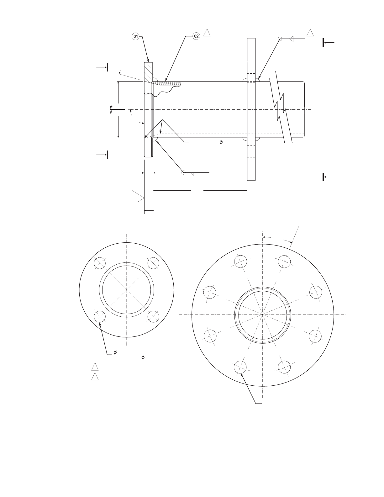
2
.187
.187
1
B
A
o
15
3.584
3.554
A
90
o
ON INSIDE BREAK
FOR SMOOTH
ROUNDED EDGE ON
BOTH ENDS
OF CHAMFER
NOTES:
.45 MIN
125
SKIN CUT FACE FOR 90
.187
6.00
VIEW A
0.75 THRU 4 PLS,
EQ SP ON 4.75 B.C.
1 WELD ON BOTH SIDES WITH EXPANDING
CHILL BLOCK.
2 BEFORE WELDING, BUTT ITEM 2 OR 4 WITH
ITEM 1 AS SHOWN.
B
o
VIEW B
o
22.5
.745
DIA ON A 7.50 DIA B.C. (REF)
.755
Figure 1-7. Abrasive Shield Assembly
NOTE
In highly abrasive applications, rotate the shield 90 degrees at norm al
service intervals to present a new wear surface to the abrasive flow stream.
APPENDIX A
IB-106-300N S E RIES
1-5
16860033

P0010
19280010
Figure 1-8. Ceramic Diffusi on /Du s t S eal As s embly
These modified diffusion and vee deflector
assemblies are available in standard, Figure 1-8,
and flame arrestor ve rsion , Fig u re 1- 9.
b. Ceramic Diffusion Assembly. The ceramic
diffusion assembly, Figure 1-10, is the traditional
design for the probe. Used for over 25 years, the
ceramic diffusion assembly provides a greater filter
surface area for the probe.
Figure 1-10. Ceramic Diffusion Ass embly
c. Flame Arrestor Diffusion Assembly. Where a
high concentration of unburned fuel is present in
the exhaust gases, a flame arrestor diffusion
assembly, Figu res 1- 9 an d 1- 11 is recommended.
The flame diffusion assembly includes a set of
baffles between the cell and the stack gases. This
keeps 1500°F (816°C) cell temperatures from
igniting unburned fuel in the stack.
Figure 1-9. Flame Arrestor Diffusion/Dust
Seal Assembly
P0012
P0011
Figure 1-11. Flame Arrestor Diffusion Assembly
APPENDIX A
IB-106-300N S E RIES
1-6

Figure 1-12. Snubber Diffusion/Dust Seal Assembly
d. Snubber Diffusion/Dust Seal Assembly. The
snubber diffusion/dust seal assembly, Figure 1-12,
is used in applications where an abrasive shield is
to be used with a snubber type diffusion element.
The dust seal consists of two rings of packing to
prevent abrasive dust from collecting inside the
abrasive shield.
e. Bypass Probe Options. For processes where the
flue gas exceeds the maximum allowable
temperature of 1300°F (704°C) a bypass sensor
package can be employed. The bypass system uses
an 18 inch (457 mm) or 3 foot (0.92 m) probe
mounted externally on the stack or duct. The
process or exhaust gases are directed out to the
probe through a passive sampling system using
inconel tubes. Flue gas flow induces the movement
of gases into, through, and out of the bypass unit.
The bypass arrangement does not require the use
of aspiration air and the gas which flows past the
probe is returned to the st ack or du ct .
The bypass probe package is normally used for
process temperatures of 1300°F (704°C) to 2000°F
(1094°C). A higher temperature version of the
bypass provides for operation at temperatures up to
2500°F (1372°C). In this version the pick up tubes
are made of a special high- temperature alloy.
Overall dimensions and mounting details of the
American and European bypass systems are shown
in Figure 1-13.
f. Probe Mounting Jacket Options. A probe
mounting jacket option is available to allow the
probe to operate at temperatures of up to 2000°F
(1095°C). A separate instruction bulletin is
available for this option.
APPENDIX A
IB-106-300N S E RIES
1-7
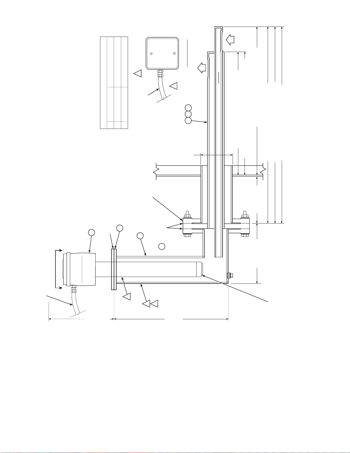
A-A
OF FLOW
DIRECTION
27270017
REFERENCE AIR SUPPLY CONNECTION BITE TYPE FITTING (PARKER CPI) FOR
0.250 O.D. TUBING. 2 SCFH AT 3 PSIG MAX. CLEAN DRY AIR REQUIRED. FITTING
IS LOCATED ON FAR SIDE.
1.
NOTES:
CALIBRATION AND PURGE GAS CONNECTION. BITE TYPE FITTING (PARKER CPI)
10 SCFH AT 32 PSIG MAX. CALIBRATION GAS REQUIRED.
LAG TO ENSURE GAS TEMPERATURE DOES NOT GO BELOW DEW POINT OR
2.
3.
o
EXCEED 500 C.
A
oooo
RECOMMENDED TWO INCH THK INSULATION. THERMAL CONDUCTIVITY K
FLUE GAS OPERATING TEMPERATURE RANGE 1200 TO 1800 F (650 TO 980 C).
INSTALL WITH ANALYZER IN A VERTICALLY DOWNWARDS DIRECTION ONLY.
6.
4.
5.
EQUALS 0.5 FOR INSULATION.
DIMENSIONS ARE IN INCHES WITH MILLIMETERS IN PARENTHESES.
7.
01
GROUP NOTE
A 3 FT (914.4) GAS TUBE PICK-UP
FLANGE
B 6 FT (1828.8) GAS TUBE PICK-UP
C 9 FT (2743.2) GAS TUBE PICK-UP
GASKET AND HARDWARE
06
CAL
GAS
2
ELECT CABLE
BY CUSTOMER
OPTIONAL MOUNTING
ARRANGEMENT, 4 IN.
150# FLANGE SUPPLIED
05
HARDWARE
GASKET AND
06
REF
1
AIR
4.026
VIEW
04
02 03
I.D.
(102.26)
30.62 (777.75) REF (4507C26G01)
62.50 (1587.5) REF (4507C26G03)
26.50 (673.1) REF (4507C26G01 AND G02)
6.0
(152.4) REF
6.50
(165.1) REF
37.00 (939.8) REF (4507C26G01)
73.00 (1854.2) REF (4507C26G02)
109.00 (2768.6) REF (4507C26G03)
STD 20 FT
(6.1 M) CABLE
DRAIN
A
4
6
3
FOR
FOR PROBE
27.31 (693.67)
CLEARANCE REQ
INSERTION
AND REMOVAL
3D3947G01
19.80 (502.92)
IF EQUIPPED WITH THE OPTIONAL
CERAMIC DIFFUSOR ASSEMBLY, PROBE
VEE SHIELD IS SQUARE TO GAS FLOW.
ASSEMBLY MUST BE ORIENTED SO THAT
Figure 1-13. Bypass Probe Option (Sheet 1 of 3)
APPENDIX A
IB-106-300N S E RIES
1-8

A-A
27270018
o
0.250 O.D. TUBING. 2 SCFH AT 3 PSIG (20.69 kPa GAUGE) MAX. CLEAN DRY AIR
1.
NOTES: REFERENCE AIR SUPPLY CONNECTION BITE TYPE FITTING (PARKER CPI) FOR
CALIBRATION AND PURGE GAS CONNECTION. BITE TYPE FITTING (PARKER CPI)
REQUIRED. FITTING IS LOCATED ON FAR SIDE.
2.
o
o
10 SCFH AT 32 PSIG (220.64 kPa GAUGE) MAX. CALIBRATION GAS REQUIRED.
LAG TO ENSURE GAS TEMPERATURE DOES NOT GO BELOW DEW POINT OR
EXCEED 932 F (500 C).
INSTALL WITH ANALYZER IN A VERTICALLY DOWNWARDS DIRECTION ONLY.
3.
4.5.6.
AA
oo
o
01
FLUE GAS OPERATING TEMPERATURE RANGE 1200 TO 1800 F (650 TO 980 C).
RECOMMENDED 2.0 INCH (50.8) THK INSULATION. THERMAL CONDUCTIVITY K EQUAL
0.5 FOR INSULATION.
DIMENSIONS ARE IN INCHES WITH MILLIMETERS IN PARENTHESES.
7.
FLANGE
GROUP NOTE
A 3 FT (914.4) GAS TUBE PICK-UP
08
06 07
B 6 FT (1828.8) GAS TUBE PICK-UP
C 9 FT (2743.2) GAS TUBE PICK-UP
AND
GASKET
HARDWARE
CAL
GAS
2
ELECT
CABLE
10
09
05
WELD BY CUSTOMER
16
15
14
REF
AIR
1
13
12
11
VIEW
04
03
02
OF FLOW
DIRECTION
I.D.
4.026
(102.26)
PLATE
WELDED
TO STACK
PICKUP (3D390004G07 OR G08)
26.5 (673.1) ON 3 FT (914.4) OR 6 FT (1828.8)
37.0 (939.8) ON 3 FT (914.4) PICKUP (3D390004G07)
73.0 (1854.2) ON 6 FT (1828.8) PICKUP (3D390004G08)
62.5 (1587.5) ON 9 FT (2743.2) PICKUP (3D390004G09)
109.0 (2768.6) ON 9 FT (2743.2) PICKUP (3D390004G09)
STD CABLE
20 FT (6.1 M)
FOR PROBE
27.31 (693.67)
CLEARANCE REQ
INSERTION
AND REMOVAL
3
4
FOR
19.80
(502.92)
3D3947G01
6
Figure 1-13. Bypass Probe Option (Sheet 2 of 3)
APPENDIX A
IB-106-300N S E RIES
1-9
DRAIN
6.50 (165.1) REF
IF EQUIPPED WITH THE OPTIONAL
CERAMIC DIFFUSOR ASSEMBLY, PROBE
VEE SHIELD IS SQUARE TO GAS FLOW.
ASSEMBLY MUST BE ORIENTED SO THAT
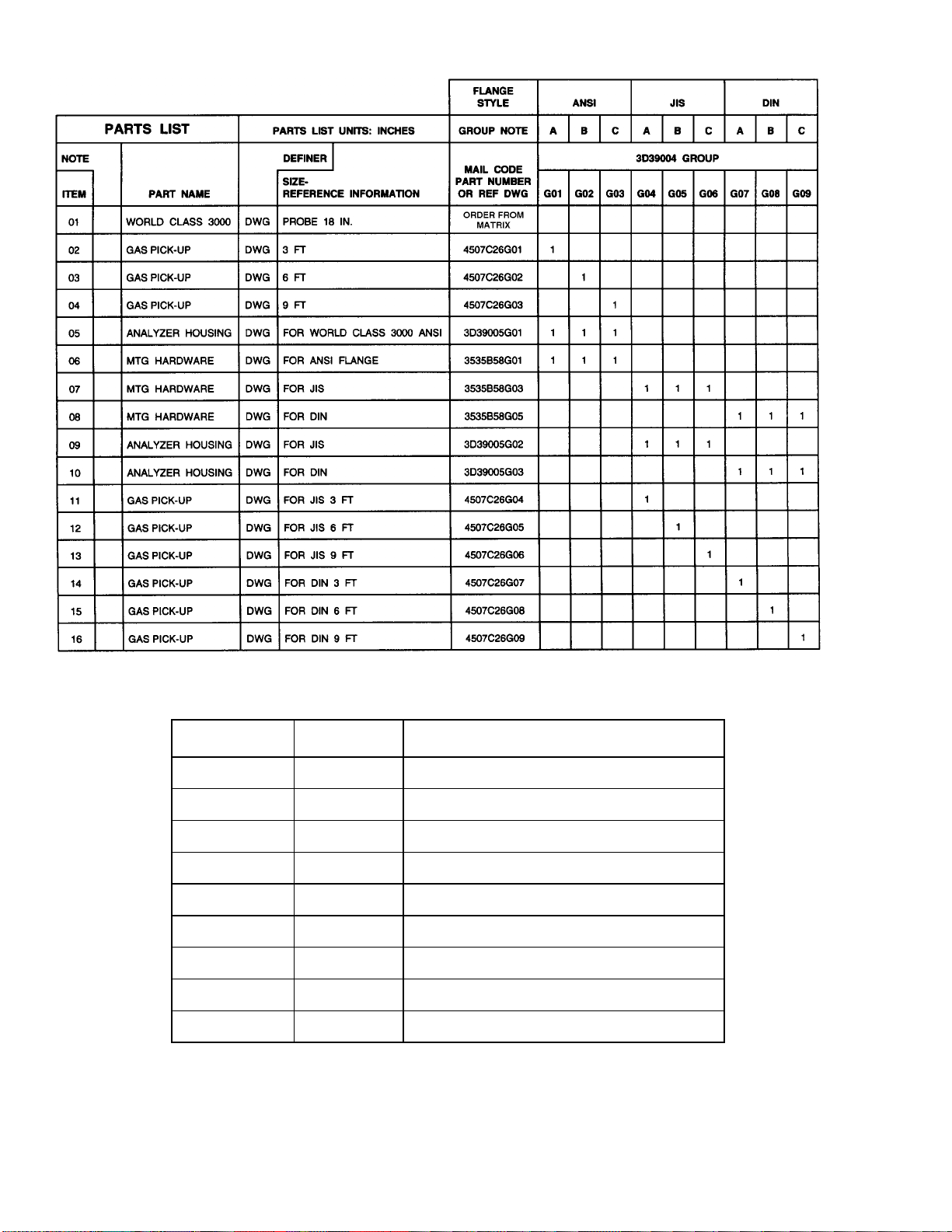
Extended Temperature By-Pass Arrangements (2400°F; 1300°C)
PART NO. GROUP
CODE DESCRIPTION
1U0571 G01 3’ By-pass Package with ANSI bolt pattern.
1U0571 G02 6’ By-pass Package with ANSI bolt pattern.
1U0571 G03 9’ By-pass Package with ANSI bolt pattern.
1U0571 G04 3’ By-pass Package with JIS bolt pattern.
1U0571 G05 6’ By-pass Package with JIS bolt pattern.
1U0571 G06 9’ By-pass Package with JIS bolt pattern.
1U0571 G07 3’ By-pass Package with DIN bolt pattern.
1U0571 G08 6’ By-pass Package with DIN bolt pattern.
1U0571 G09 9’ By-pass Package with DIN bolt pattern.
Figure 1-13. Bypass Probe Option (Sheet 3 of 3)
APPENDIX A
IB-106-300N S E RIES
1-10
SECTION II. PROBE TROUBLESHOOTING
2-1. OVERVIEW.
The probe troubleshooting section
describes how to identify and isolate faults which may
develop in the probe assembly.
Install all protective equipment covers and
safety ground leads after troubleshooting.
Failure to replace covers and ground leads
could result in serious injury or death.
2-2. PROBE TROUBLESHOOTING.
a. Probe Faults. Listed below are the four symptoms
of probe failure.
1. The s ystem does not respond to ch an g e s i n
the oxygen concen tration .
SYMPTOM CHECK FAULT REMEDY
1. No response to oxygen
concentration change
when:
2. The s ystem responds to oxygen changes but
does not give the correct indication.
3. The system does not give an acceptable
indication of the value of the oxygen calibration gas being applied during calibration.
4. The system takes a long time to return to the
flue gas value after the calibration gas is
turned off.
b. Table 2-1 provides a guide to fault finding for the
above symptoms.
c. Figures 2-1 and 2-2 provide an alternate approach
to finding probe relate d problems.
Table 2-1. Fault Finding.
Heater is cold and TC
mV output is less than
set point
Heater is hot and T/C
mV output is at set
point ±0.2 mV
Thermocouple continuity
Heater cold resistance to be
11 ohm to 14 ohm
Triac O/P to heater
Recorder chart
Cell mV input to electronics
and cell mV at probe
junction box
Thermocouple failure
Heater failure
Failure of electronics
Recorder failure
No cell mV at probe when
calibration gas applied
Probe cell mV OK but no
input to electronics
Cell mV satisfactory both at
probe junction box an d input
to electronics - failure of
electronics
Replace thermocouple or
return probe to Rosem ount.
Replace heater or return
probe to Rosemount.
Check HPS and electronics
package.
See Recorder Instruction
Manual.
Replace cell or return probe
to Rosemount.
Check out cable connection.
Check electronics package.
APPENDIX A
IB-106-300N S E RIES
2-1

Table 2-1. Fault Finding (Continued).
SYMPTOM CHECK FAULT REMEDY
2. System responds t o
oxygen concentration
changes but does n ot
give correct indication
Good response, wit h
incorrect indication
3. System does not give
accurate indication of
applied calibration gas
4. System takes a long
time to return to flue
gas value after calibration gas is turned off
Recorder or remote indicator
Calibration error
Recalibrate recorder or
indicator. Reference
Recorder Instruction
Manual.
System calibration
Probe mounting and
Calibration error
Air ingress into duct
Recalibrate system.
Stop air leaks or resite probe.
condition of duct
Cell mV input to electronics
Calibration gas input port
Failure of electronics
Blocked port
Check electronics package.
Clean port. If the flue gas is
condensing in the calibration
gas line, insulate the back of
the probe. Make sure that the
calibration gas line is capped
between calibrations, or a
check valve is installed.
Ceramic diffus i on element
Diffusion elemen t crack ed,
Replace diffusion elem en t.
broken, or missi n g
Diffusion element Plugged diffusion element Change diffusion element or
snubber diffu si on el ement.
APPENDIX A
IB-106-300N S E RIES
2-2

Figure 2-1. Flowchart of Probe Related Problem s , #1
APPENDIX A
IB-106-300N S E RIES
2-3

Figure 2-2. Flowchart of Probe Related Problem s , #2
APPENDIX A
IB-106-300N S E RIES
2-4

SECTION III. SERVICE AND NORMAL MAINTENANCE
NOTE
Upon completing installation, make sure that the probe is turned on and
operating prior to firing u p the combustion process. Damage can result from
having a cold probe exposed to the process gases.
During outages, and if possible, leave all probes running to prevent
condensation and premature aging from thermal cycling.
If the ducts will be washed down during outage, MAKE SURE to power down
the probes and remove them from the wash area.
3-1. OVERVIEW.
maintenance of the oxygen analyzer probe. Spare parts
referred to are available from Rosemount. Probe
disassembly kit 3535B42G01 contains the required
spanner and hex wrenches. Refer to Section IV of this
appendix for part numbers and ordering inform at ion .
Install all protective equipment covers and
safety ground leads after equipment repair
or service. Failure to install covers and
ground leads could result in serious injury or
death.
3-2. PROBE RECALIBRATION.
system should be calibrated when commissioned.
Under normal circumstances the probe will not require
frequent calibration. When calibration is required,
follow the procedure described in the Instruction
Bulletin applicable to your electronics package.
This section describes routine
The oxygen analyzer
packaged to preserve precise surface finishes. Do not
remove items from packaging until they are ready to be
used. Spanner wrenches and hex wrenches needed for
this procedure are part of an available special tools kit,
Table 4-1.
Wear heat resistant gloves and clothing to
remove probe from stack. Normal operating
temperatures of diffusor and vee deflector
are approximately 600° to 800°F (316° to
427°C). They could cause severe b urn s .
Disconnect and lock out power before
working on any electrical components.
There is voltage up to 115 Vac.
Do not remove cell unless it is certain that
replacement is needed. Removal may damage
cell and platinum pad. Go through complete
troubleshooting procedure to make sure cell
needs replacement before removing it.
3-3. CELL REPLACEMENT.
oxygen sensing cell replacement. Do not attempt to
replace the cell until all other possibilities for poor
performance have been considered. If cell replacement
is needed, order cell replacement kit, Table 4-1.
The cell replacement kit contains a cell and flange
assembly, corrugated seal, setscrews, socket head cap
screws, and anti-seize compound. Items are carefully
This paragraph covers
APPENDIX A
IB-106-300N SERIES
3-1
Disconnect and lock out power to electronics. Shut
a.
off and disconnect reference air and calibration gas
supplies from probe junction box, Figure 3-1.
Wearing heat resistant gloves and clothing, remove
probe assembly from stack carefully and allow to
cool to room temperature. Do not attempt to work
on unit until it has cooled to a comfortable working
temperature.

BOMB TAIL
CONNECTOR
CELL EXTENSION
WIRE (ORANGE)
INCONEL
CELL WIRE
(CLEAR
SLEEVING)
HEATER
WIRES
(BLACK
SLEEVING)
THERMOCOUPLE -
(RED ALUMEL)
THERMOCOUPLE +
(YELLOW CHROMEL)
CALIBRATION
GAS FITTING
CABLE
Figure 3-1. Cell Wiring Connection
If the probe uses the standard diffusion element,
b.
use a spanner wrench to remove the diffusion
element.
If equipped with the optional ceramic diffusor
c.
assembly, remove and discard setscrews, Figure
3-2, and remove vee deflector. Use spanner
wrenches f rom probe disassembly k i t, Table 4-1, to
turn hub free from retainer. Inspect diffusion
element. If damag ed, replace element.
Loosen four socket head cap screws from the cell
d.
and flange assembly and remove the assembly
and the corrugated seal. The cell flange has a
REFERENCE
AIR FITTING
PROBE JUNCTION
BOX COVER
27270019
notch which may be used to gently pry the flange
away from the probe. Note that the contact pad
inside the probe will sometimes fuse to the
oxygen sensing cell. If the cell is fused to the
contact pad, push the cell assembly back into the
probe (against spring pressure), and quickly twist
the cell assembly. The cell and contact pad
should separate.
If the contact pad stays fused
to the cell, a new contact/thermocouple assembly
must be installed. Disconnect the cell and the
thermocouple wires at the probe junction box,
and withdraw the cell with the wires still attached
(see paragraph 3-5).
APPENDIX A
IB-106-300N S E RIES
3-2

PIN
WRENCH
RETAINER
OPTIONAL CERAMIC
DIFFUSION ELEMENT
HUB
CEMENT
PORT
CEMENT
FILLET
Figure 3-2. Removal of Optional Diffu s or
and Vee Deflector
PROBE TUBE
(NOT INCLUDED
IN KIT)
CORRUGATED
SEAL
CALIBRATION GAS
PASSAGE
SETSCREW
VEE
DEFLECTOR
21240026
CELL AND
FLANGE
ASSEMBLY
SOCKET HEAD
CAP SCREWS
Assemble cell and flange assembly, corrugated
h.
seal, and probe tube. Make sure the calibration
tube lines up with the calibration gas passage in
each component. Apply a small amount of
anti-seize compound to screw threads and use
screws to secure assembly. Torque to 55 in-lbs
•
(4 N
m).
Apply anti-seize compound to threads of cell
i.
assembly, hub, and setscrews. Reinstall hub on c ell
assembly. Using pin spanner wrenches, torque to
10 ft-lbs (14 N
•
m). If applicable, reinstall vee
deflector, orienting apex toward gas flow. Secure
with setscrews and anti-seize compound. Torque
to 25 in-lbs (2.8 N
On systems equipped with an abrasive shield,
j.
install dust seal gaskets, with joints 180
Reinstall probe and gasket on stack flange. If there
k.
is an abrasive shield in the stack, make sure dust
seal gaskets are in place as they enter 15
•
m).
o
apart.
o
reducing
cone.
Turn power on to electronics and monitor
l.
thermocouple output. It should stabilize at 29.3
±0.2 mV. Set reference air flow at 2 scfh
(56.6 L/hr). After probe stabilizes, calibrate probe
per Instruction Bulletin applicable to your
electronics package. If new components have been
installed, repeat calibration after 24 hours of
operation.
3-4. OPTIONAL CERAMIC DIFFUSION ELEMENT
REPLACEMENT.
Figure 3-3. Cell Replacement Kit
If contact assembly is damaged, replace contact
e.
and thermocouple according to paragraph 3-5,
Replacement of Contact and Thermocouple
Assembly.
Remove and discard corrugated seal. Clean mating
f.
faces of probe tube and retainer. Remove burrs and
raised surfaces with block of wood and crocus
cloth. Clean threads on retainer and h u b.
Rub a small amount of anti-seize on both sides of
g.
new corrugated seal.
21240009
APPENDIX A
IB-106-300N S E RIES
3-3
a. General.
The diffusion element protects the cell
from particles in process gases. It does not
normally need to be replaced because the vee
deflector protects it from particulate erosion. In
severe environments the filter may be broken or
subject to excessive erosion. Examine the diffusion
element whenever removing the probe for any
purpose. Replace if damag ed.
Damage to the diffusion element may become
apparent during calibration. Compare probe
response with previous response. A broken
diffusion element will cause a slower response to
calibration gas.
Hex wrenches needed to remove setscrews and
socket head screws in the following procedure are
available as part of a special tool kit, Table 4-1.

Wear heat resistant gloves and clothing to
remove probe from stack. Normal operating
temperatures of diffusor and vee deflector
are approximately 600° to 800°F (300° to
425°C). They can cause severe burn s .
6. Break out remaining diffusion element by
tapping lightly around hub with hammer.
Clean grooves w ith poin ted tool if necessary.
7. Replace diffusion element, using replacement
kit listed in Table 4-1. This consists of a
diffusion element, cement, setscrews,
anti-seize compound and in s tru ction s .
Disconnect and lock out power before
working on any electrical component.
There is voltage up to 115 Vac.
It is not necessary to remove the cell unless it
is certain that replacement is necessary. Cell
cannot be removed for inspection without
damaging it. Refer to paragraph 3-3, Cell
Replacement.
b. Replacement Procedure.
1. Shut off power to electronics. Disconnect
cable conductors and remove cable, Figure
3-1. Shut off and disconnect reference air and
calibration gas supplies from probe junction
box. Wearing heat resistant gloves and
clothing, carefully remove probe assembly
from stack and allow to cool to room
temperature. Do not attempt to work on unit
until it has cooled to a comfortable working
temperature.
2. Loosen setscrews, Figure 3-2, using hex
wrench from special tools kit, Table 4-1, and
remove vee deflector. Inspect setscrews. If
damaged, replace with M-6 x 6 stainless
setscrews coated w ith anti-seize compound.
3. On systems equipped with abrasive shield,
remove dual dust seal g as k ets .
8. Test fit replacement element to be sure seat is
clean.
Do not get cement on diffusion element
except where it touches the hub. Any cement
on ceramic element blocks airflow through
element. Wiping wet cement off of ceramic
only forces cement into pores.
9. Thoroughly mix cement and insert tip of
squeeze bottle into cement port. Tilt bottle
and squeeze while simultaneously turning
diffusion element into seat. Do not get any
cement on upper part of diffusion element.
Ensure complete penetration of cement
around three gro oves in hub. Cement should
extrude from opposite hole. Wipe excess
material back into holes and wipe top fillet of
cement to form a uniform fillet. (A Q-Tip is
useful for this.) Clean any excess cement from
hub with water.
10. Allow filter to dry at room temperature
overnight or 1 to 2 h ou rs at 200° F (93°C ).
11. Wipe a heavy layer of anti-seize compound
onto the threads and mating surfaces of the
diffusion h u b an d ret ainer.
12. Assemble retainer and diffusion hub with
two pin spanner wrenches. Torque to 10 ft-lbs
(14 N•m).
4. Use spanner wrenches from special tools kit,
Table 4-1, to turn hub free from retainer.
5. Put hub in vise. Break out old diffusion
element with chisel along cement line and
3/8 inch (9.5 mm) pin punch thr ough cement
port.
APPENDIX A
IB-106-300N S E RIES
13. On systems equipped with abrasive shield,
install dust s eal g a s k ets with joints 180° apart.
14. Reinstall vee deflector, orienting apex toward
gas flow. Apply anti-seize compound to
setscrews and tigh ten with hex wrench.
3-4
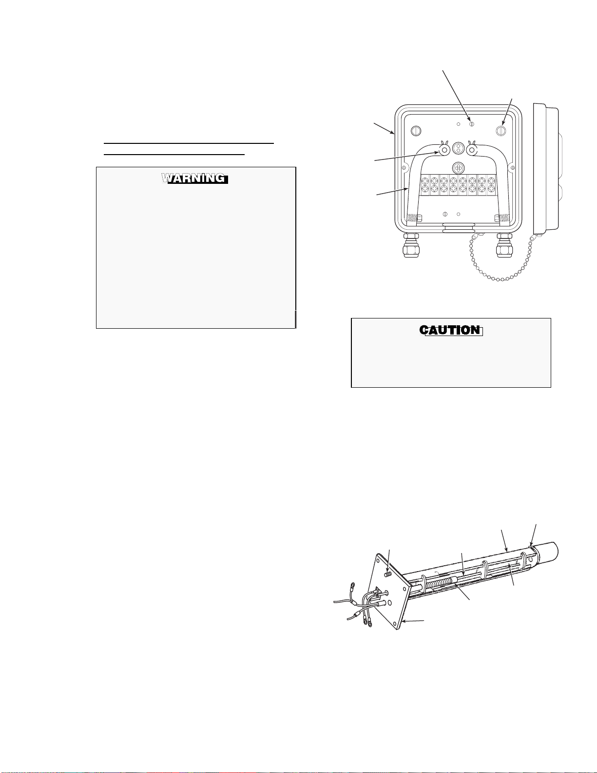
15. R ei n s tal l probe on s t ack f l an g e.
21240010
MOUNTING SCREW
(REAR VIEW)
CONTACTAND
THERMOCOUPLER
ASSEMBLY
V-STRUT
HEATER SCREWS
(NOT SHOWN)
HEATER
CERAMIC ROD
SPRING
CLIP
INSULATING
GASKET
16. Turn power on to electronics and monitor
thermocouple output. It should stabilize at
29.3 ±0.2 mV. Calibrate probe per Instruction
Bulletin applicable to your electronics
package.
3-5. REPLACEMENT OF CONTACT AND
THERMOCOUPLE ASSEMBLY.
.
Use heat resistant gloves and clo thing when
removing probe junction box and inner
probe assembly. Do not attempt to work on
these components until they have cooled to
room temperature. Probe components can
be as hot as 800°F (427°C). This can cause
severe burns.
Disconnect and lock out power before
working on any electrical components. There
is voltage up to 115 Vac.
PROBE JUNCTION BOX TO HEATER,
STRUT, AND BACKPLATE
ASSEMBLYSCREW
PROBE JUNCTION BOX
INNER PROBE ASSEMBLY
TO PROBE TUBE SCREWS
PROBE
JUNCTION
BOX
HOSE
CLAMP
HOSE
21240027
Figure 3-4. Probe Junction Box Mechanical Conn ecti ons
Disconnect and lock out power to electronics.
a.
Using heat resistant gloves and clothing, remove
probe junction box cover. Squeezing tabs on hose
clamps, remove hoses from probe junction box,
Figure 3-4. Remove four screws in corners of
probe junction box. Pull probe junction box and
inner probe assembly free from probe tube. Set on
bench and allow to cool t o room temperature.
Disconnect cell extension wire (orange),
b.
thermocouple wire (red alumel), and thermocouple
wire (yellow chromel) by cutting bomb tail
connections from th e terminal strip, Figure 3-1.
Remove two screws, Figure 3-4, lockwashers, and
c.
flat washers that connect probe junction box to
inner probe assembly. Pull heater, V-strut and
backplate assembly away from probe junction box.
Inspect all O-rings and insulating gasket; replace if
worn or damag ed.
Use a pencil to mark locations of spring clip on
d.
ceramic rod, Figure 3-5.
Pry or squeeze tabs on spring clips, and pull
e.
contact and thermocouple assembly out of probe
assembly. Retain spring clips and spring; replace if
damaged.
Be very careful when handling contact and
thermocouple assembly. The ceramic rod in
this assembly is fragile.
While very carefully handling new contact and
f.
thermocouple assembly, lay old assembly next to
new one. Transf er pen ci l marks to new rod.
Note wire lengths of old assembly as an aid for
g.
trimming new lengths in step (j). Trimming of
wires will not always be necessary. Throw away
old contact and thermocouple assembly.
Figure 3-5. Inner Probe Replacement
(Heater, V-Strut, and Backplate Assembly)
APPENDIX A
IB-106-300N S E RIES
3-5
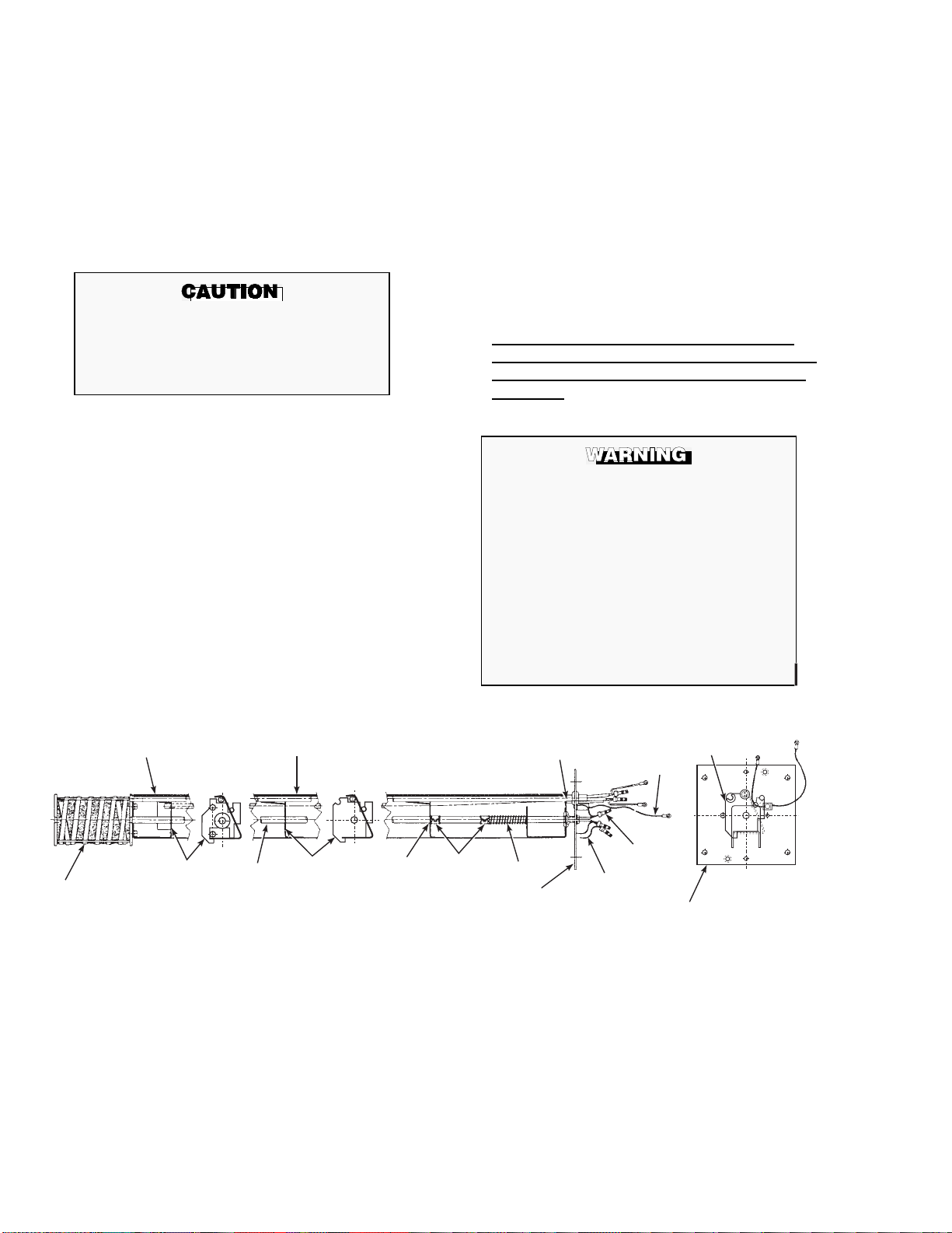
Carefully guide new contact and thermocouple
h.
assembly through V-strut assembly leaf spring
(4, Figure 3-6), spring (9), spring clip (10) (held
open by squeezing tabs), and tube supports
(11, 13) until spring clip reaches pencil mark.
Reinstall insulating gasket on backplate, replace
i.
two screws, O-rings, lockwashers and flat
washers connecting probe junction box to inner
probe assembly.
Slide assembled probe junction box and inner
l.
probe assembly into probe tube. To align
calibration gas tube with corresponding hole in
backplate (A, B, Figure 1-1), insert scriber
through hole in backpl ate and into c alib ra tion gas
tube. Secure with screws. Reinstall hoses and
probe junction box cover.
Power up system. Monitor thermocouple output.
m.
It should stabilize at set point mV ±0.2 mV.
Recalibrate probe per Instruction Bulletin
applicable to your electronics package.
Do not trim new wiring shorter than existing
(old) wiring. Excessive wire trim will prevent
connections from being properly made and
will require a new replacement kit.
Trim wires, if necessary, as noted in step (g).
j.
Connect color coded wires to proper terminals as
k.
shown in Figure 3-1. Rosemount recommends
connecting the thermocouple wires directly to the
terminal strip. This is because the junction of
different metals at the wires and lugs and at the
lugs and the terminal strip could act as add itional
thermocouple junctions. This could produce a
voltage that would affect the thermocouple
output signal.
Do not bend wires closer than 1/4 inch (6.4 mm)
from end of ceramic rod. Dress wires so they do
not touch sides of probe junction box.
1
3
3-6. REPLACEMENT OF HEATER, V-STRUT
AND BACKPLATE ASSEMBLY (Inner Probe
Assembly; Includes Contact and Thermocouple
Assembly).
Use heat resistant gloves and clothing when
removing probe junction box and inner
probe assembly. Do not attempt to work on
these components until they have cooled to
room temperature. Probe components can be
as hot as 800° (427°C). This can cause severe
burns.
Disconnect and lock out power before
working on any electrical components. There
is voltage up to 115 Vac.
4
5
4
6
1011
9
8
7
12
13
2
11
1. Heater Ceramic Rod 5. Ring Lug 19. Spring
2. Contact and Thermocouple Assembly 6. Butt Connector 10. Spring Clip Assembly
3. Strut 7. Extension Wire 11. Comm on Tube S u pport
4. Leaf Spring 8. Backplate 12. Heater
13. Short Tube Support
Figure 3-6. Heater, Strut, and Backplate Assembly
(Inner Probe Assembly)
APPENDIX A
IB-106-300N S E RIES
3-6
8

NOTE
This replacement may be done without
removing the probe from the duct.
Disconnect and lock out power to electronics.
a.
Using heat resistant gloves and clothing, remove
probe cover. Squeezing tabs on hose clamps and
remove hoses from probe j unctio n b ox, Figure 3 -4.
Remove four screws and lockwashers (7, 10,
Figure 3-7) that hold probe junction box and inner
probe assembly to probe tube. Pull probe junction
box and inner probe assembly free from probe
tube. Set on bench and allow to cool to room
temperature.
Disconnect cell extension wire (orange),
b.
thermocouple wire (red alumel), and thermocouple
wire (yellow chromel) by cutting bomb tail
connections from th e terminal strip, Figure 3-1.
Remove two screws, lockwashers, and flat washers
c.
that connect probe junction box to inner probe
assembly. Remove and discard inner probe
assembly (heater, V-strut, and backplate
assembly). Replace with new inner probe
assembly. Reinstall screws, lockwashers and flat
washers.
Connect color coded wires to proper terminals as
d.
shown in Figure 3-1. Rosemount recommends
connecting the thermocouple wires directly to the
terminal strip. This is because the junction of
different metals at the wires and lugs and at the
lugs and the terminal strip could act as additional
thermocouple junctions. This could produce a
voltage that would affect the thermocouple output
signal.
Do not bend wires closer than 1/4 inch (6.4 mm)
from end of ceramic rod. Dress wires so they do
not touch sides of probe junction box.
Slide assembled probe junction box and inner
e.
probe assembly into probe tube. To align
calibration gas tube with corresponding hole in
backplate (A, B, Figure 1-1), insert aligning tool
(included in probe disassembly kit, P/N
3535B42G01) through hole in backplate and into
calibration gas tube, while sliding the heater strut
into the probe tube. Secure with screws. Reinstall
hoses and probe junc ti on box cov e r.
ITEM
1
2
3
4
5
124
3
DESCRIPTION
Snubber Diffus i on
Element
Socket Hd
Cap Screw
Cell and Flange
Assembly
Corrugated Seal
Probe Tube
Assembly
11
SIZE-REFERENCE
INFORMATION ITEM
6
0.25 in.-28
7
x 0.63 (16 mm)
8
9
10
11
5
DESCRIPTION
Gasket
Fillister Hd
Screw
Cover Head
Assembly
Hose Clamp
Lockwasher
Heater Strut
Assembly
678 9
10
21240012
SIZE-REFERENCE
INFORMATION
4.0 in. (102 mm) x 4.0 in. x
0.12 in. (3 mm)
8-32 x 0.5 in.
(12.7 mm)
#8 Split
Figure 3-7. Oxygen Analyzer (Probe), Cross-Sectional View
APPENDIX A
IB-106-300N S E RIES
3-7

Power up system. Monitor thermocouple output. It
f.
should stabilize at set point ±0.2 mV. Recalibrate
probe per Instruction Bulletin applicable to your
electronics package.
Do not use sealant when installing the
stainless steel tubes. Gas samples may
become contaminated
3-7. CALIBRATION GAS AND REFERENCE AIR
LINES FOR HIGH TEMPERATURE CORROSIVE ENVIRONMENT OPERATION.
A
high temperature, corrosive environment kit is available
when the probe is exposed to these types of operating
conditions. The kit includes stainless steel tubing and
teflon fittings for inside the probe junction box. The kit
part number is 4843B93G01.
a. Installation Procedure.
Use heat resistant gloves and clothing
when removing probe junction box and
inner probe assembly. Do not attempt to
work on these components until they have
cooled to room temperature. Probe
components can be as hot as 800°F (427°C).
This can cause severe burns.
Disconnect and lock out power before
working on any electrical components. There
is voltage up to 115 Vac.
2. First install the stainless steel tubing on the
fitting at the bottom of the probe junction box.
Install the other end of the stainless steel tube
onto the tube going to the probe (Figure 3-8).
NOTE
If abrasive conditions of h i gh ash content and
high velocity exist, an abrasive shield is
recommended. To balance out the wear on
the shield, rotate the shield 90° every time the
probe is powered down for service.
TEFLON
SLEEVES
STAINLESS
STEEL
TUBING
1. Disconnect and lock out power to digital
electronics. Using heat resistant gloves and
clothing, remove probe cover. Squeezing tabs
on hose clamps, remove hoses from probe
junction box (Figure 3-4).
APPENDIX A
IB-106-300N S E RIES
21240028
Figure 3-8. High Temperature - Corrosive
Environment Kit
3-8

SECTION IV. REPLACEMENT PARTS
Table 4-1. Replacement Parts for Probe.
FIGURE and
INDEX No. PART NUMBER DESCRIPTION
3-5
3-5
3-5
3-5
3-5
3-6, 2
3-6, 2
3-6, 2
3-6, 2
3-6, 2
1-7
1-7
1-7
1-7
3-3
3-3
3-3
3-3
3-3
3-3
3-3
3-3
3-3
3-3
3-3
3-3
3-3
3-3
3-3
3-3
3-3
3-3
3-3
1-10
1-8
1-10
1-9
1-11
1-4
3-2
3D39441G06
3D39441G07
3D39441G08
3D39441G09
3D39441G10
3534B56G04
3534B56G05
3534B56G06
3534B56G07
3534B56G08
3D39003G01
3D39003G02
3D39003G07
3D39003G08
4847B61G01
4847B61G02
4847B61G03
4847B61G04
4847B61G05
4847B61G06
4847B61G07
4847B61G08
4847B61G09
4847B61G10
4847B61G11
4847B61G12
4847B61G13
4847B61G14
4847B61G15
4847B61G16
4847B61G17
4847B61G18
3535B42G01
3534B18G01
3535B60G01
4841B03G02
3535B63G01
3535B62G01
3534B48G01
6292A74G02
1537B70G03
3-8
1-1,2
1-12
1
Heater, V-strut, and backplate assembly includes contact and thermocouple ass embly.
2
Contact and thermocouple assembly includes platinum pad and in con el wire.
3
Abrasive shield assem bly includes accessories necessary for its u s e an d a mounting plate and gasket.
4843B93G01
4843B37G01
4843B38G02
1
1
1
1
1
2
2
2
2
2
3
3
3
3
Heater, V-Strut , and Ba ck pl at e A sse m bly, 18 in. (45.6 cm)
Heater, V-Strut, and Backplate Assembly, 3 ft (0.9 m)
Heater, V-Strut, and Backplate Assembly, 6 ft (1.8 m)
Heater, V-Strut, and Backplate Assembly, 9 ft (2.7 m)
Heater, V-Strut, and Backplate Assembly, 12 ft (3.6 m)
Contact and Thermocouple Assembly, 18 in. ( 45.6 c m )
Contact and Thermocouple Assembly, 3 ft ( 0.9 m )
Contact and Thermocouple Assembly, 6 ft ( 1.8 m )
Contact and Thermocouple Assembly, 9 ft ( 2.7 m )
Contact and Thermocouple Assembly, 12 ft ( 3.6 m )
Abrasive Shield Assembly, 3 ft (0.9 m)
Abrasive Shield Assembly, 6 ft (1.8 m)
Abrasive Shield Assembly, 9 ft (2.7 m)
Abrasive Shield Assembly, 12 ft (3.6 m)
Cell Replacement Kit, ANSI, No Lead Wire
Cell Replacement Kit, ANSI 18 in. (45.6 cm)
Cell Replacement Kit, ANSI 3 ft (0.9 m)
Cell Replacement Kit, ANSI 6 ft (1.8 m)
Cell Replacement Kit, ANSI 9 ft (2.7 m)
Cell Replacement Kit, ANSI 12 ft (3.6 m)
Cell Replacement Kit, JIS, No Lead Wire
Cell Replacement Kit, JIS 18 in. (45.6 cm)
Cell Replacement Kit, JIS 3 ft (0.9 m)
Cell Replacement Kit, JIS 6 ft (1.8 m)
Cell Replacement Kit, JIS 9 ft (2.7 m)
Cell Replacement Kit, JIS 12 ft (3.6 m)
Cell Replacement Kit, DIN, No Lead Wire
Cell Replacement Kit, DIN 18 in. (45.6 cm)
Cell Replacement Kit, DIN 3 ft (0.9 m)
Cell Replacement Kit, DIN 6 ft (1.8 m)
Cell Replacement Kit, DIN 9 ft (2.7 m)
Cell Replacement Kit, DIN 12 ft (3.6 m)
Probe Disassembly Kit
Diffuser Assembly
Diffuser Dust Seal Hub Assembly
(For use with Abrasive Shield)
Stainless Steel Diffuser Assembly
Flame Arrestor Diffuser Dust Seal
Flame Arrestor Diffuser
Vee Deflector Assembly
(For use with sta ndar d or dust se a l type ceramic diffuser s)
Diffusion Element Replacement Kit
Horizontal and Vertical Brace Clamp Assembly,
9 and 12 foot (2.7 and 3.6 m) probe
High Temperature - Corrosive Environment Kit
Snubber Diffusion Assembly
Dust Seal/Snubber Di ffusion A ssembly
APPENDIX A
IB-106-300N S E RIES
4-1/4-2
Loading...