

Wet Gas Flow Measurement with Conditioning Orifice Meter Flow Test Data Book and Flow Handbook
Table of contents
 Loading...
Rosemount Wet Gas Flow Measurement with Conditioning Orifice Meter Flow Test Data Book and Flow Handbook Manuals & Guides
Page 1

Reference Manual
00821-0200-4810, Rev BA
May 2014
Flow Test Data Book and Flow Handbook for
Wet Gas Flow Measurement with Conditioning
Orifice Meter
Page 2

Page 3

Reference Manual
NOTICE
00809-0100-4021, Rev GC
Flow Test Data Book and Flow
Handbook for Wet Gas Flow
Measurement with Conditioning
Orifice Meter
Title Page
May 2014
Read this manual before working with the product. For personal and system safety, and for
optimum product performance, make sure to thoroughly understand the contents before
installing, using, or maintaining this product.
Customer Central
1-800-999-9307 (7:00 a.m. to 7:00 P.M. CST)
National Response Center
1-800-654-7768 (24 hours a day)
Equipment service needs
International
1-(952) 906-8888
The products described in this document are NOT designed for nuclear-qualified applications.
Using non-nuclear qualified products in applications that require nuclear-qualified hardware or
products may cause inaccurate readings.
For information on Rosemount
Management
Emerson Process Management satisfies all obligations coming from legislation to
harmonize product requirements in the European Union.
®
Sales Representative.
®
nuclear-qualified products, contact an Emerson Process
iii
Page 4

Title Page
May 2014
Reference Manual
00821-0200-4810, Rev BA
iv
Page 5

Reference Manual
00821-0200-4810, Rev BA
Contents
1Section 1: 405C Compact Conditioning Orifice Plate and 1595
2Section 2: Theory of Operation
Table of Contents
May 2014
Conditioning Orifice Plate
1.1 Product Features . . . . . . . . . . . . . . . . . . . . . . . . . . . . . . . . . . . . . . . . . . . . . . . . . . . . . . .1
1.2 Testing . . . . . . . . . . . . . . . . . . . . . . . . . . . . . . . . . . . . . . . . . . . . . . . . . . . . . . . . . . . . . . . .2
1.2.1 Structural Testing . . . . . . . . . . . . . . . . . . . . . . . . . . . . . . . . . . . . . . . . . . . . . . . . . 2
1.2.2 Independent Testing . . . . . . . . . . . . . . . . . . . . . . . . . . . . . . . . . . . . . . . . . . . . . .2
1.3 Product Specifications. . . . . . . . . . . . . . . . . . . . . . . . . . . . . . . . . . . . . . . . . . . . . . . . . . .2
2.1 Overview . . . . . . . . . . . . . . . . . . . . . . . . . . . . . . . . . . . . . . . . . . . . . . . . . . . . . . . . . . . . . . 5
2.2 Technical Detail . . . . . . . . . . . . . . . . . . . . . . . . . . . . . . . . . . . . . . . . . . . . . . . . . . . . . . . .5
2.3 Conditioning Orifice Meter Technology. . . . . . . . . . . . . . . . . . . . . . . . . . . . . . . . . . . .6
3Section 3: Test Facilities and Flow Tests
3.1 Overview . . . . . . . . . . . . . . . . . . . . . . . . . . . . . . . . . . . . . . . . . . . . . . . . . . . . . . . . . . . . . . 7
3.2 Testing Laboratories . . . . . . . . . . . . . . . . . . . . . . . . . . . . . . . . . . . . . . . . . . . . . . . . . . . .7
3.3 Flow Tests . . . . . . . . . . . . . . . . . . . . . . . . . . . . . . . . . . . . . . . . . . . . . . . . . . . . . . . . . . . . .8
4Section 4: Flow Calculations
4.1 Rosemount 405C and 1595 Conditioning Orifice Plate . . . . . . . . . . . . . . . . . . . . .25
4.1.1 Calculated Values and Variables Designations . . . . . . . . . . . . . . . . . . . . . . .25
4.1.2 Equations . . . . . . . . . . . . . . . . . . . . . . . . . . . . . . . . . . . . . . . . . . . . . . . . . . . . . . .26
4.2 Flow Calculation Tables. . . . . . . . . . . . . . . . . . . . . . . . . . . . . . . . . . . . . . . . . . . . . . . . .30
5Appendix A Additional Graphs
Rosemount 1595 Calculated offset from measured versus Lockhart-Martinelli
Number. . . . . . . . . . . . . . . . . . . . . . . . . . . . . . . . . . . . . . . . . . . . . . . . . . . . . . . . . . . .33
Rosemount 405C Calculated offset from measured versus Lockhart-Martinelli
Number . . . . . . . . . . . . . . . . . . . . . . . . . . . . . . . . . . . . . . . . . . . . . . . . . . . . . . . . . . . .33
CEESI Facility Diagram. . . . . . . . . . . . . . . . . . . . . . . . . . . . . . . . . . . . . . . . . . . . . . . .34
Tab le of C ontents
v
Page 6

Table of Contents
May 2014
Reference Manual
00821-0200-4810, Rev BA
vi
Table of Contents
Page 7

Reference Manual
00821-0200-4810, Rev BA
Section 1: 405C Compact Conditioning Orifice Meter
and 1595 Conditioning Orifice Plate
Section 1 405C Compact Conditioning
Orifice Meter and 1595
Conditioning Orifice Plate
Product features . . . . . . . . . . . . . . . . . . . . . . . . . . . . . . . . . . . . . . . . . . . . . . . . . . . . . . . . . . . . page 1
Testing . . . . . . . . . . . . . . . . . . . . . . . . . . . . . . . . . . . . . . . . . . . . . . . . . . . . . . . . . . . . . . . . . . . . page 2
Product specifications . . . . . . . . . . . . . . . . . . . . . . . . . . . . . . . . . . . . . . . . . . . . . . . . . . . . . . . page 2
1.1 Product features
The Rosemount® 405C Compact Conditioning Orifice Meter and 1595 Conditioning Orifice
Plate primary flow elements maintain the traditional strengths of orifice plate technology with
improved features / performance.
May 2014
The strengths of the 405C include:
More economical than a Traditional Orifice Plate Installation
Accurate and repeatable
Short straight run requirements
Self centering mechanism
Based on ASME/ISO Corner Tap Design
The strengths of the 1595 include:
Based on the most common primary element in the world with established standards
for manufacture and installation.
Easy to use, prove, and troubleshoot
Accurate and repeatable
Short straight run requirements
Based on ASME/ISO/AGA Standards
The 405C and 1595 Primary Flow Elements are sized using Rosemount's Instrument Toolkit
sizing program. This program provides accurate flow calculations using installation details and
fluid properties for the flowmeter and presents this on a calculation data sheet or specification
sheet.
™
1
Page 8

Section 1: 405C Compact Conditioning Orifice Meter
and 1595 Conditioning Orifice Plate
May 2014
1.2 Testing
Tests performed on the 405C / 1595 Primary Flow Elements are divided into two major
categories:
Mechanical and structural testing
Independent laboratory testing
All categories are on going and continue to be a part of the current Rosemount test program for
the 405C / 1595 Primary Flow Elements.
1.2.1 Structural testing
Rosemount performed integrity testing for:
Allowable stress limits
Hydrostatic pressure
Thermal effects
Vibration
Reference Manual
00821-0200-4810, Rev BA
At the following labs:
Hauser Laboratories, Boulder, CO
Rosemount Vibration Laboratory, Eden Prairie, MN
1.2.2 Independent testing
Rosemount 405C and 1595 Primary Flow Element models were tested in wet gas conditions at
the following independent laboratories:
Colorado Engineering Experiment Station, Inc. (CEESI)
Certified flow-data sheets were supplied from each of these facilities. Representative samples of
tests conducted at the independent laboratories are in Section 3: Test Facilities and Flow Tests.
1.3 Product specifications
The above testing has enabled Rosemount to provide product which conforms to the following
specifications in wet gas applications. See Appendix A for graphical representations of how well
the curve fit matched the actual data.
Table 1-1. Rosemount 405C Compact Conditioning Orifice
Beta ratio Discharge coefficient uncertainty
= 0.40 ± 0.50%
= 0.50 ± 1.0%
= 0.65 ± 1.0%
2
Page 9

Reference Manual
00821-0200-4810, Rev BA
Section 1: 405C Compact Conditioning Orifice Meter
and 1595 Conditioning Orifice Plate
May 2014
Table 1-2. Rosemount 1595 Conditioning Orifice
Beta ratio Discharge coefficient uncertainty
= 0.40 ± 0.50%
= 0.50 ± 1.0%
= 0.65 ± 1.0%
3
Page 10

Section 1: 405C Compact Conditioning Orifice Meter
and 1595 Conditioning Orifice Plate
May 2014
Reference Manual
00821-0200-4810, Rev BA
4
Page 11

Reference Manual
QKDP=
P
1
1
2
-- -
V
1
2
+ P
2
1
2
-- -
V
2
2
+=
00821-0200-4810, Rev BA
Section 2: Theory of Operation
Section 2 Theory of Operation
Overview . . . . . . . . . . . . . . . . . . . . . . . . . . . . . . . . . . . . . . . . . . . . . . . . . . . . . . . . . . . . . . . . . . page 5
Technical detail . . . . . . . . . . . . . . . . . . . . . . . . . . . . . . . . . . . . . . . . . . . . . . . . . . . . . . . . . . . . . page 5
Conditioning orifice meter technology . . . . . . . . . . . . . . . . . . . . . . . . . . . . . . . . . . . . . . . . . page 6
2.1 Overview
The Rosemount® 405C and 1595, based on orifice plate technology, is a device used to measure
the flow of a liquid, gas, or steam fluid that flows through a pipe. It enables flow measurement
by creating a differential pressure (DP) that is proportional to the square of the velocity of the
fluid in the pipe, in accordance with Bernoulli's theorem. This DP is measured and converted into
a flow rate using a secondary device, such as a DP pressure transmitter.
The flow is related to DP through the following relationship.
May 2014
Equation 1
where:
Q = Flow rate
K = Units conversion factor, discharge coefficient, and other factors
DP = Differential pressure
For a more complete discussion on the flow equation, refer to Section 4: Flow Calculations.
2.2 Technical detail
As stated previously, traditional orifice plate flowmeters are based on Bernoulli's theorem,
which states that along any one streamline in a moving fluid, the total energy per unit mass is
constant, being made up of the potential energy (the pressure energy), and the kinetic energy of
the fluid. Where:
where:
P
= Upstream pressure
1
P
= Downstream pressure
2
p = Density
= Upstream velocity
V
1
V
= Downstream velocity
2
When fluid passes through the orifice the velocity of the fluid through the orifice increases. This
increase in fluid velocity causes the kinetic energy of the fluid immediately downstream of the
orifice plate to increase, while simultaneously decreasing the static pressure energy of the fluid
at that same point. By sensing the static pressure on the upstream and downstream sides of the
orifice plate, the fluid velocity can be determined.
5
Page 12

Section 2: Theory of Operation
Actual
Theoretical
May 2014
Some assumptions were made in deriving the theoretical equation, which in practice are not
valid:
a. Energy is conserved in the flow stream.
b. Pressure taps are at ideal locations.
c. Velocity profile is flat.
These items are corrected by the discharge coefficient which is derived from experimental data
and is different for each primary element.
Discharge Coefficient C =
2.3 Conditioning orifice meter technology
The Rosemount 405C and 1595 Conditioning Orifice Plate has the added advantage of being
able to operate with reduced straight run requirements. With its multiple orifices in the flow
stream it is much less susceptible to velocity profile distortion, swirl, and secondary flows. If the
velocity profile is skewed, each of the orifices will conduct a part of the total fluid flow within the
pipe. The fluid pressure on the downstream side of the conditioning plate that is attributable to
each of the separate orifices will be averaged within the fluid to provide an average downstream
pressure. The average downstream pressure is compared with the upstream pressure to provide
an average differential pressure for whatever velocity profile is presented to the multiple orifice
plate, resulting in an accurate measurement of the rate of fluid flow in the pipe.
Reference Manual
00821-0200-4810, Rev BA
As mentioned in an earlier section, every 405C and 1595 is flow calibrated as part of the
manufacturing process. The purpose of this calibration is to determine a calibration factor
which is applied to the flow calculations as an adjustment to correct for bias error from the
ISO-5167 discharge coefficient equations. This results in an accurate flowmeter which conforms
to the ISO-5167 equations.
6
Page 13

Reference Manual
00821-0200-4810, Rev BA
Section 2: Test Facilities and Flow Tests
Section 3 Test Facilities and Flow Tests
Overview . . . . . . . . . . . . . . . . . . . . . . . . . . . . . . . . . . . . . . . . . . . . . . . . . . . . . . . . . . . . . . . . . . page 7
Testing laboratories . . . . . . . . . . . . . . . . . . . . . . . . . . . . . . . . . . . . . . . . . . . . . . . . . . . . . . . . . page 7
Flow tests . . . . . . . . . . . . . . . . . . . . . . . . . . . . . . . . . . . . . . . . . . . . . . . . . . . . . . . . . . . . . . . . . . page 8
3.1 Overview
The following descriptions of tests and testing methods are abbreviated versions. For detailed
descriptions of the individual laboratories contact the facility in question.
3.2 Testing laboratories
May 2014
CEESI, Colorado
Colorado Engineering Experiment Station, Inc. (CEESI) in Nunn, Colorado has a multi phase flow
test facility using natural gas and hydrocarbon liquids. The facility accommodates line sizes from
2 to 8 inch at a max pressure of 1440 Psi. The facility operates at temperatures ranging from
ambient to 122 °F. See Appendix A Additional Graphs for a diagram of CEESI facility.
Lean natural gas is brought into the CEESI complex at a low pressure of near 0.3 Mpa (50 psi). A
charging compressor is used to pressurize the test loop to the desired operating pressure for the
test being conducted. The normal operating pressure range is between 0.7 to 9.9 Mpa (100 to
1440 psi). Once the loop is pressurized, any combination of the four positive displacement
compressors can be used to circulate the natural gas around the test loop at the desired
velocity. Both a turbine meter and a subsonic venturi measure the mass flow rate of the natural
gas. The difference in mass flow rate between these two meters is monitored; and if the
difference exceeds a specified amount, the data is scrutinized for detrimental effects such as
pulsation. If the difference is within tolerance, then all other meters installed in the test loop can
be compared to the natural gas mass flow rate as measured by the turbine meter.
The hydrocarbon liquid, which resides in the liquid storage vessel, can be injected into the gas
stream by positive displacement pumps (triplex pumps). Coriolis meters measure the liquid
mass flow rate and the density of the injected liquid. The gas stream carries the liquid through
the meter test locations to the horizontal separator where it is then returned to the liquid
storage vessel. Coriolis meters again measure the mass flow rate and the density of the returned
liquid. When the injected liquid mass flow rate is equal to the return liquid mass flow rate and all
pressures and temperatures within the loop are constant with time; the system is at a steady
state condition and test data can be acquired.
7
Page 14

Section 2: Test Facilities and Flow Tests
May 2014
3.3 Flow tests
A summary of the tests is provided on the following pages (see Section 4 for descriptions of
terminology and calculation methods used).
Table 3-1. Natural Gas, 0.65 Beta Ratio
Model: 1595 Pipe Size: 3-in. (76.2 mm) Schedule 40
Fluid: Natural Gas Pipe I.D.: 3.068
Beta Ratio: 0.65 Tes t Date: 4/1 2/04
Figure 3-1. 200 PsiA Baseline
Reference Manual
00821-0200-4810, Rev BA
Test laboratory: CEESI, Colorado
Table 3-2. Decane and Natural Gas, 0.65 Beta Ratio
Test laboratory: CEESI, Colorado
Model: 1595 Pipe Size: 3-in. (76.2 mm) Schedule 40
Fluid: Decane & Natural Gas Pipe I.D.: 3.068
Beta Ratio: 0.65 Tes t Date: 4/1 4/04
Figure 3-2. 200 PsiA Wet Gas CEESI
8
Page 15

Reference Manual
00821-0200-4810, Rev BA
Section 2: Test Facilities and Flow Tests
May 2014
Table 3-3. 3" Rosemount 1595 0.65 Beta 200PsiA Baseline
Temperature Pressure Viscosity Density
Data
point
°F °C PsiA Bar cp lb/ft
1 73.6 23.1 235.3 16.2 0.0111 0.7996 341.651 4.2332 2,831,911 0.6047 0.6059 0.191
2 76.6 24.8 229.8 15.8 0.0111 0.7752 216.496 3.3430 2,232,940 0.6055 0.6061 0.095
3 78.1 25.6 227.7 15.7 0.0111 0.7654 147.801 2.7563 1,839,350 0.6060 0.6063 0.061
4 80.0 26.6 226.1 15.6 0.0111 0.7567 99.578 2.255 9 1,503,546 0.606 2 0.6066 0.071
5 80.2 26.8 225.0 15.5 0.0111 0.7527 59.566 1.749 3 1,165,868 0.608 1 0.6070 -0.192
6 80.1 26.7 223.6 15.4 0.0111 0.7479 36.180 1.358 3 905,451 0.6071 0.6073 0.044
7 78.9 26.1 222.1 15.3 0.0111 0.7447 18.205 0.964 8 643,829 0.6086 0.6079 -0.110
Differential
pressure
3
inH20 lb/sec Gas C
Flow
rate
Pipe
Reynold s #
Discharge
coefficient
c
Iso 5167
calculation
C
d
Deviation
from ISO
Table 3-4. 3” Rosemount 1595 0.65 Beta 200PsiA Wet Gas
d
Lockhart
Martinelli
#
X %
Over-
reading
Temperature Pressure Viscosity
Data
point
°F °C PsiA Bar cp in H20 lb/ft
1 70.7 21.5 219.1 15.1 0.0110 333.087 0.7344 46.0517 3.6243 1.7346 2,433,962 0.539 0.060 1.105
2 77.6 25.3 218.5 15.1 0.0111 312.433 0.7218 45.8610 3.6757 0.8496 2,456,430 0.569 0.029 1.047
3 83.0 28.4 218.3 15.0 0.0111 301.252 0.7128 45.7118 3.7110 0.3336 2,469,437 0.589 0.011 1.013
4 85.9 29.9 218.6 15.1 0.0112 297.782 0.7097 45.6324 3.7203 0.1762 2,469,592 0.595 0.006 1.003
5 86.4 30.2 218.4 15.1 0.0112 295.023 0.7085 45.6183 3.7352 0.0418 2,478,384 0.600 0.001 0.993
6 75.9 24.4 213.9 14.7 0.0111 156.427 0.7086 45.9172 2.5253 1.1183 1,690,692 0.553 0.055 1.080
7 78.4 25.8 213.0 14.7 0.0111 147.892 0.7020 45.8490 2.5455 0.5834 1,701,137 0.576 0.028 1.037
8 80.6 27.0 211.8 14.6 0.0111 132.986 0.6948 45.7915 2.4602 0.2514 1,641,548 0.589 0.013 1.013
9 81.6 27.5 211.7 14.6 0.0111 131.023 0.6930 45.7630 2.4681 0.1173 1,645,483 0.596 0.006 1.001
10 82.9 28.3 211.6 14.6 0.0111 131.203 0.6906 45.7270 2.4852 0.0263 1,655,136 0.601 0.001 0.993
11 74.6 23.6 212.3 14.6 0.0111 118.840 0.7053 45.9568 1.7247 3.8203 1,155,970 0.433 0.274 1.380
12 78.7 25.9 209.5 14.4 0.0111 82.033 0.6898 45.8481 1.6529 1.9085 1,104,828 0.505 0.142 1.186
13 80.5 26.9 209.3 14.4 0.0111 70.473 0.6865 45.7973 1.6476 1.0801 1,099,688 0.544 0.080 1.101
14 82.4 28.0 208.4 14.4 0.0111 61.381 0.6808 45.7452 1.6301 0.3862 1,086,450 0.578 0.029 1.034
15 84.8 29.4 208.4 14.4 0.0111 56.448 0.6775 45.6785 1.5871 0.2091 1,055,657 0.589 0.016 1.017
16 77.8 25.4 208.0 14.3 0.0111 28.593 0.6865 45.8749 0.8752 2.1386 585,501 0.452 0.299 1.325
17 79.8 26.6 207.5 14.3 0.0111 21.466 0.6817 45.8192 0.8758 0.9223 584,958 0.524 0.128 1.144
18 81.2 27.3 207.0 14.3 0.0111 19.366 0.6781 45.7822 0.8760 0.5997 584,499 0.553 0.083 1.084
19 81.5 27.5 206.6 14.2 0.0111 17.194 0.6763 45.7742 0.8775 0.2208 585,368 0.589 0.031 1.018
20 81.8 27.7 206.5 14.2 0.0111 16.763 0.6756 45.7661 0.8780 0.1327 585,564 0.597 0.018 1.004
Differential
pressure
Gas
density
3
Liquid
density
Flow rate
Flow rate
(gas)
(liquid)
lb/sec lb/sec Gas C
Pipe
Reynold s #
Discharge
coefficient
%
9
Page 16

Section 2: Test Facilities and Flow Tests
May 2014
Table 3-5. Natural Gas, 0.40 Beta Ratio
Model: 1595 Pipe Size: 3-in. (76.2 mm) Schedule 40
Fluid: Natural Gas Pipe I.D.: 3.068
Beta Ratio: 0.40 Tes t Date: 4/2 1/04
Figure 3-3. 200 PsiA Baseline
Reference Manual
00821-0200-4810, Rev BA
Test laboratory: CEESI, Colorado
Table 3-6. Decane and Natural Gas, 0.40 Beta Ratio
Test laboratory: CEESI, Colorado
Model: 1595 Pipe Size: 3-in. (76.2 mm) Schedule 40
Fluid: Decane & Natural Gas Pipe I.D.: 3.068
Beta Ratio: 0.40 Tes t Date: 4/2 1/04
Figure 3-4. 200 PsiA Wet Gas CEESI
10
Page 17

Reference Manual
00821-0200-4810, Rev BA
Section 2: Test Facilities and Flow Tests
May 2014
Table 3-7. 3” Rosemount 1595 0.40 Beta 200PsiA Baseline
Temperature Pressure Viscosit y Densit y
Data
point
°F °C PsiA Bar cp lb/ft3inH20 lb/sec Gas C
1 69.1 20.6 256.0 16.2 0.0111 0.8831 1041.026 2.6394 1,766,747 0.5974 0.5999 0.412
2 68.1 20.1 233.6 15.8 0.0110 0.8042 647.578 2.0177 1,355,021 0.5987 0.6000 0.204
3 68.7 20.4 223.8 15.7 0.0110 0.7681 499.329 1.7433 1,171,610 0.5995 0.6000 0.088
4 70.2 21.2 214.3 15.6 0.0110 0.7322 332.108 1.3977 939 ,423 0.5995 0.6001 0.103
5 69.5 20.9 204.7 15.5 0.0110 0.6992 159.701 0.9567 643 ,936 0.6009 0.6003 -0.096
6 68.0 20.0 201.2 15.4 0.0110 0.6888 96.944 0.7451 502,227 0.6034 0.6 004 -0.491
7 66.4 19.1 197.6 15.3 0.0110 0.6785 55.653 0.5601 378 ,028 0.6019 0.6006 -0.218
Differential
pressure
Pipe Reynolds #Discharge
Flow rate
coefficient
c
Iso 5167
calculation
C
d
Deviation
from ISO
Table 3-8. 3" Rosemount 1595 0.40 Beta 200PsiA Wet Gas
d
Lockhart
Martinelli
#
X %
Temperature Pressure Viscosity
Data
point
°F °C PsiA Bar cp inH20 lb/ft
1 66.6 19.2 277.4 19.1 0.0111 1300.693 0.9834 46.0522 2.8164 1.1656 1,883,085 0.543 0.060 1.098
2 69.9 21.1 270.7 18.7 0.0111 1208.647 0.9514 45.9757 2.7986 0.5959 1,868,821 0.568 0.031 1.050
3 72.0 22.2 266.4 18.4 0.0111 1126.780 0.9313 45.9275 2.7556 0.2519 1,838,565 0.584 0.013 1.021
4 72.2 22.3 265.2 18.3 0.0111 1112.637 0.9267 45.9254 2.7705 0.1076 1,848,561 0.592 0.006 1.007
5 72.3 22.4 261.5 18.0 0.0111 1064.019 0.9128 45.9301 2.7175 0.0218 1,813,923 0.597 0.001 0.998
6 63.3 17.4 234.6 16.2 0.0110 607.365 0.8306 46.2251 1.8504 0.8023 1,246,124 0.556 0.058 1.076
7 65.2 18.4 231.5 16.0 0.0110 565.211 0.8157 46.1787 1.8366 0.4098 1,235,897 0.576 0.030 1.038
8 65.4 18.5 228.6 15.8 0.0110 527.198 0.8046 46.1795 1.8094 0.1510 1,217,900 0.591 0.011 1.012
9 65.1 18.4 227.8 15.7 0.0110 520.606 0.8023 46.1896 1.8110 0.0739 1,219,256 0.596 0.005 1.003
10 64.6 18.1 227.2 15.7 0.0110 517.339 0.8011 46.2046 1.8122 0.0166 1,220,538 0.599 0.001 0.999
11 56.9 13.8 212.2 14.6 0.0110 302.138 0.7579 46.4453 1.0331 2.4024 699,835 0.455 0.297 1.318
12 60.2 15.7 209.8 14.5 0.0110 272.074 0.7432 46.3588 1.0480 1.7124 708,942 0.491 0.207 1.222
13 63.2 17.3 207.5 14.3 0.0110 234.292 0.7301 46.2813 1.0225 1.1113 690,688 0.520 0.137 1.155
14 66.8 19.3 204.9 14.1 0.0110 197.941 0.7151 46.1863 1.0216 0.4187 688,801 0.570 0.051 1.053
15 69.9 21.0 204.1 14.1 0.0110 188.402 0.7075 46.1014 1.0306 0.1385 693,555 0.592 0.017 1.013
16 57.1 13.9 201.2 13.9 0.0109 101.620 0.7162 46.4631 0.5954 1.3905 403,737 0.461 0.290 1.304
17 57.3 14.1 200.2 13.8 0.0109 90.285 0.7119 46.4583 0.5964 1.0169 404,432 0.491 0.211 1.224
18 59.1 15.0 199.3 13.7 0.0109 78.676 0.7059 46.4111 0.5906 0.5987 400,201 0.523 0.125 1.150
19 61.0 16.1 198.6 13.7 0.0109 69.082 0.7004 46.3595 0.5939 0.2394 402,066 0.563 0.050 1.068
20 63.0 17.2 198.3 13.7 0.0110 64.862 0.6961 46.3045 0.5948 0.0734 402,258 0.584 0.015 1.030
Differential
pressure
Gas
density
3
Liquid
density
Flow rate
Flow rate
(gas)
(liquid)
lb/sec lb/sec Gas C
Pipe
Reynold s #
Discharge
coefficient
%
Over-
reading
11
Page 18
Section 2: Test Facilities and Flow Tests
May 2014
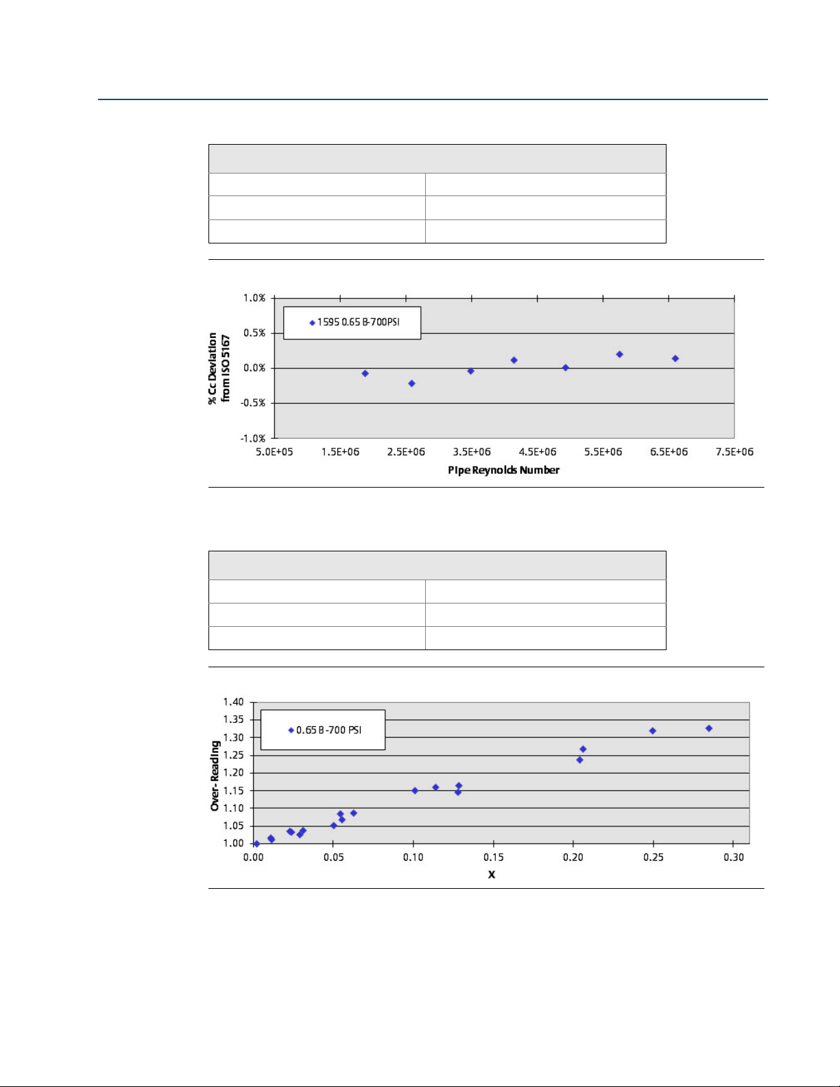
Table 3-9. Natural Gas, 0.65 Beta Ratio
Model: 1595 Pipe Size: 3-in. (76.2 mm) Schedule 40
Fluid: Natural Gas Pipe I.D.: 3.068
Beta Ratio: 0.65 Tes t Date: 4/1 5/04
Figure 3-5. 700 PsiA Baseline
Reference Manual
00821-0200-4810, Rev BA
Test laboratory: CEESI, Colorado
Table 3-10. Decane and Natural Gas, 0.65 Beta Ratio
Test laboratory: CEESI, Colorado
Model: 1595 Pipe Size: 3-in. (76.2 mm) Schedule 40
Fluid: Decane & Natural Gas Pipe I.D.: 3.068
Beta Ratio: 0.65 Tes t Date: 4/1 9/04
Figure 3-6. 700 PsiA Wet Gas CEESI
12
Page 19

Reference Manual
00821-0200-4810, Rev BA
Section 2: Test Facilities and Flow Tests
May 2014
Table 3-11. 3" Rosemount 1595 0.65 Beta 700PsiA Baseline
Temperature Pressure Viscosity Density
Data
point
°F °C PsiA Bar cp lb/f t3inH20 lb/sec Gas C
1 84 .1 28. 9 710.9 49.0 0.0122 2.4871 713.649 10.8476 6,596,205 0.6042 0.6051 0.148
2 85 .2 29. 5 706.5 48.7 0.0122 2.4632 545.520 9.4613 5,7 54,535 0.6040 0.6052 0.201
3 85 .3 29. 6 702.6 48.4 0.0122 2.4472 398.461 8.0966 4,9 28,799 0.6053 0.6053 0.010
4 85 .1 29. 5 698.6 48.2 0.0122 2.4332 281.653 6.7956 4,1 41,419 0.6048 0.6055 0.114
5 83 .3 28. 5 691.0 47.6 0.0121 2.4151 198.013 5.6946 3,4 81,690 0.6059 0.6056 -0.035
6 79 .2 26. 2 684.7 47.2 0.0121 2.4173 107.248 4.2090 2,5 85,171 0.6073 0.6060 -0.214
7 76 .8 24. 9 679.4 46.8 0.0120 2.4117 56.303 3.0464 1,876,532 0.6068 0 .6063 -0.074
Differential
pressure
Flow rate
Pipe
Reynolds #
Discharge
coefficient
c
Iso 5167
calculation
C
d
Deviation
from ISO
%
Table 3-12. 3" Rosemount 1595 0.65 Beta 700PsiA Wet Gas
d
Lockhart
Martinelli
#
X %
reading
Temperature Pressure Viscosity
Data
point
°F °C PsiA Bar cp inH20 lb/ft
1 74.7 23.7 739.4 51.0 0.0122 990.260 2.6451 45.00 28 11.4156 4.7571 6,938,589 0.518 0.101 1.150
2 77.6 25.4 735.3 50.7 0.0122 858.095 2.6071 44.95 04 11.2203 2.5464 6,813,684 0.550 0.055 1.083
3 79.3 26.3 734.2 50.6 0.0122 796.699 2.5911 44.91 88 11.3023 1.0862 6,857,482 0.576 0.023 1.034
4 80.2 26.8 733.6 50.6 0.0122 770.867 2.5821 44.90 09 11.3092 0.5044 6,858,156 0.587 0.011 1.015
5 81.4 27.4 733.7 50.6 0.0122 754.264 2.5744 44.87 63 11.3400 0.0987 6,870,587 0.595 0.002 1.000
6 76.5 24.7 725.1 50.0 0.0122 567.829 2.5766 44.99 22 8.5192 4.0513 5,190,748 0.514 0.114 1.159
7 78.3 25.7 722.2 49.8 0.0122 499.554 2.5519 44.95 98 8.4844 2.2293 5,166,940 0.548 0.063 1.088
8 78.9 26.0 719.2 49.6 0.0122 433.853 2.5364 44.95 34 8.3172 0.8369 5,066,832 0.577 0.024 1.032
9 79.0 26.1 718.1 49.5 0.0122 421.934 2.5313 44.95 26 8.3552 0.3969 5,090,871 0.588 0.011 1.013
10 79.6 26.4 717.6 49.5 0.0122 415.896 2.5253 44.9419 8. 4114 0.0762 5,123,738 0.5 97 0.002 0.997
11 73.7 23.2 711.4 49.1 0.0121 359.356 2.5396 45.0730 5. 9442 6.2517 3,640,777 0.4 52 0.250 1.320
12 73.7 23.2 707.7 48.8 0.0121 314.990 2.5251 45.0810 5. 7871 5.0418 3,547,999 0.4 71 0.206 1.267
13 72.9 22.7 703.8 48.5 0.0121 275.001 2.5150 45.1049 5. 8765 3.1939 3,608,197 0.5 13 0.128 1.164
14 72.5 22.5 700.6 48.3 0.0121 226.868 2.5048 45.1177 5. 8128 1.3685 3,572,631 0.5 59 0.055 1.067
15 73.2 22.9 699.5 48.2 0.0121 216.408 2.4958 45.1055 5. 8298 0.7773 3,582,438 0.5 75 0.031 1.038
16 71.0 21.7 691.8 47.7 0.0120 104.499 2.4795 45.1662 3. 1719 3.8566 1,955,553 0.4 51 0.285 1.326
17 71.6 22.0 690.7 47.6 0.0120 92.661 2.4710 45.1561 3.1971 2.7895 1,97 0,954 0.484 0.204 1.237
18 71.6 22.0 689.8 47.6 0.0120 80.828 2.4674 45.1574 3.2240 1.7635 1,98 7,913 0.522 0.128 1.145
19 71.8 22.1 689.1 47.5 0.0120 69.534 2.4630 45.1536 3.2538 0.7037 2,00 6,373 0.569 0.051 1.051
20 71.6 22.0 688.4 47.5 0.0120 65.147 2.4614 45.1592 3.2244 0.4014 1,98 8,849 0.583 0.029 1.027
Differential
pressure
Gas
density
3
Liquid
density
Flow rate
Flow rate
(gas)
(liquid)
lb/sec lb/sec Gas C
Pipe
Reynold s #
Discharge
coefficient
Over-
13
Page 20

Section 2: Test Facilities and Flow Tests
May 2014
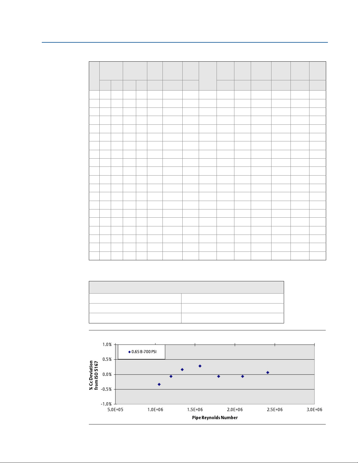
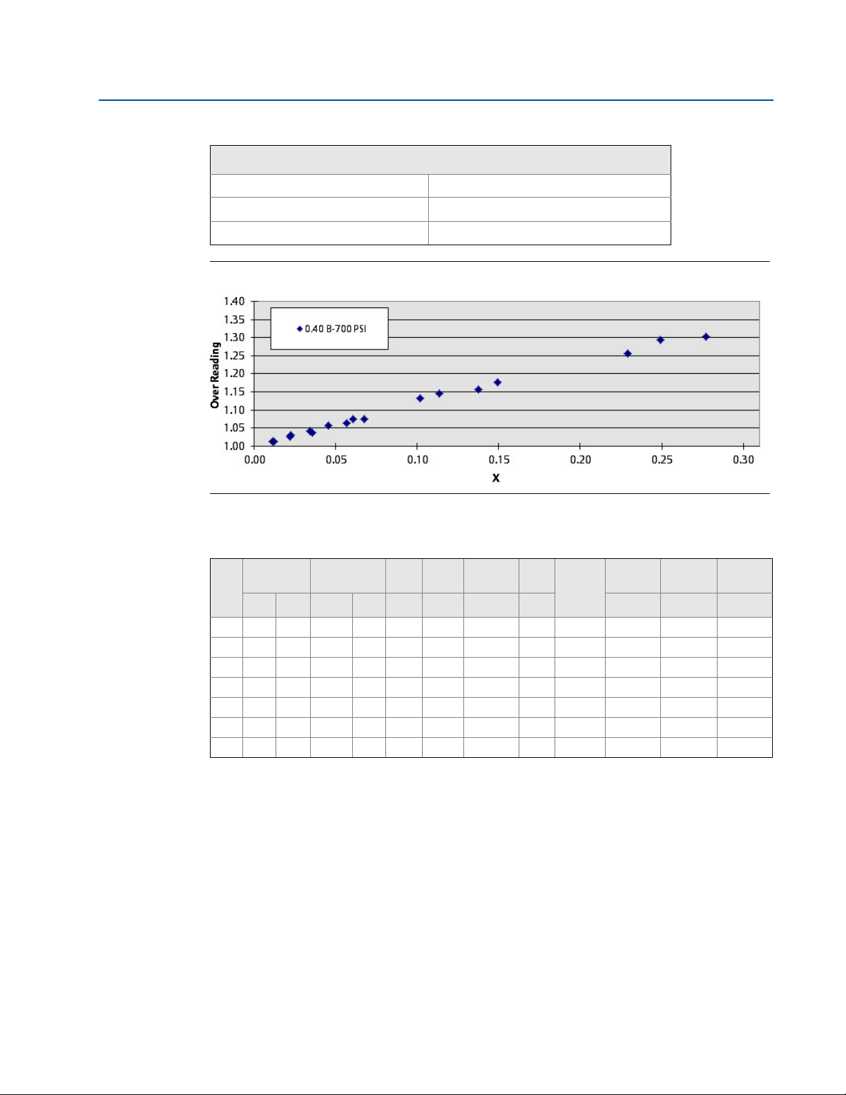
Table 3-13. Natural Gas, 0.40 Beta Ratio
Model: 1595 Pipe Size: 3-in. (76.2 mm) Schedule 40
Fluid: Natural Gas Pipe I.D.: 3.068
Beta Ratio: 0.40 Tes t Date: 4/2 0/04
Figure 3-7. 700 PsiA Baseline
Reference Manual
00821-0200-4810, Rev BA
Test laboratory: CEESI, Colorado
Table 3-14. Decane and Natural Gas, 0.40 Beta Ratio
Test laboratory: CEESI, Colorado
Model: 1595 Pipe Size: 3-in. (76.2 mm) Schedule 40
Fluid: Decane & Natural Gas Pipe I.D.: 3.068
Beta Ratio: 0.40 Tes t Date: 4/2 0/04
Figure 3-8. 700 PsiA Wet Gas CEESI
14
Page 21

Reference Manual
00821-0200-4810, Rev BA
Section 2: Test Facilities and Flow Tests
May 2014
Table 3-15. 3" Rosemount 1595 0.40 Beta 700PsiA Baseline
Temperature Pressure Viscosity Density
Data
point
°F °C PsiA Bar cp lb/ft3inH20 lb/sec Ga s C
1 76.8 24.9 740.6 51.1 0.0122 2.631 0 776.945 4.0827 2,477,386 0.5996 0.5998 0.024
2 77.3 25.2 730.2 50.3 0.0122 2.586 2 582.730 3.5156 2,138,105 0.5998 0.5998 -0.003
3 77.2 25.1 723.6 49.9 0.0122 2.560 8 423.540 2.9886 1,820,766 0.5998 0.5999 0.009
4 76.8 24.9 716.2 49.4 0.0121 2.534 4 321.574 2.5882 1,580,148 0.5984 0.5999 0.251
5 74.9 23.8 710.4 49.0 0.0121 2.524 7 233.402 2.2060 1,350,469 0.5991 0.6000 0.144
6 73.8 23.2 707.2 48.8 0.0121 2.519 7 185.544 1.9696 1,207,598 0.6001 0.6000 -0.023
7 73.7 23.2 705.6 48.6 0.0121 2.513 6 140.726 1.7210 1,055,644 0.6025 0.6001 -0.402
Differential
pressure
Flow
rate
Pipe
Reynold s #
Discharge
coefficient
c
Iso 5167
calculation
C
d
Deviation
from ISO
Table 3-16. 3" Rosemount 1595 0.40 Beta 700PsiA Wet Gas
Flow
Tem pe ra tu re Pressure Viscosity
Data
point
°F °C PsiA Bar cp inH20 lb/ft
1 69 .5 20.9 764.2 52.7 0.0122 1291.446 2.7828 45.0607 4.7198 1.9817 2,859,708 0.526 0.104 1.128
2 72 .2 22.3 760.4 52.4 0.0122 1205.072 2.7462 45.01 49 4.8526 0.9228 2,938,396 0.563 0.047 1.050
3 73 .1 22.8 758.4 52.3 0.0122 1162.222 2.7307 45.00 05 4.9070 0.4443 2,971,220 0.581 0.022 1.016
4 74 .3 23.5 747.8 51.6 0.0122 947.886 2.6792 44.9962 4.4735 0.2227 2,714,098 0.591 0.012 1.010
5 74 .3 23.5 746.9 51.5 0.0122 934.475 2.6758 44.9982 4.4990 0.0415 2,730,236 0.599 0.002 0.996
6 71 .2 21.8 742.4 51.2 0.0122 832.267 2.6812 45.0688 3.7261 1.7665 2,268,203 0.524 0.116 1.145
7 72 .3 22.4 735.3 50.7 0.0122 705.549 2.6443 45.0593 3.6343 0.9254 2,214,828 0.558 0.062 1.075
8 73 .0 22.8 730.7 50.4 0.0122 623.285 2.6207 45.0538 3.5639 0.3422 2,173,517 0.585 0.023 1.027
9 73 .7 23.2 730.7 50.4 0.0122 615.740 2.6153 45.0394 3.5897 0.1755 2,188,283 0.593 0.012 1.013
10 73 .9 23.3 730 .5 50.4 0.0122 609.320 2.6126 45.0344 3.6133 0. 0319 2,202,430 0.600 0.002 1.000
11 70 .0 21.1 726 .7 50.1 0.0121 545.518 2.6261 45.1216 2.4726 3. 3832 1,512,265 0.433 0.330 1.384
12 70 .7 21.5 722 .8 49.8 0.0121 492.848 2.6052 45.1146 2.5128 2. 6346 1,537,703 0.464 0.252 1.290
13 70 .7 21.5 718 .5 49.5 0.0121 428.321 2.5881 45.1236 2.5817 1. 6253 1,581,607 0.513 0.151 1.168
14 70 .9 21.6 715 .7 49.3 0.0121 382.330 2.5747 45.1229 2.6455 0. 7552 1,621,521 0.557 0.068 1.075
15 70 .9 21.6 714 .2 49.2 0.0121 363.614 2.5691 45.1269 2.6646 0. 4039 1,633,924 0.576 0.036 1.040
16 69 .5 20.9 713 .2 49.2 0.0121 364.015 2.5736 45.1566 2.1213 2. 4814 1,302,153 0.458 0.279 1.309
17 69 .5 20.8 710 .4 49.0 0.0121 323.586 2.5624 45.1624 2.0917 2. 0285 1,284,926 0.480 0.231 1.250
18 69 .3 20.7 707 .7 48.8 0.0121 286.448 2.5533 45.1727 2.1256 1. 2372 1,306,805 0.519 0.138 1.156
19 68 .4 20.2 704 .7 48.6 0.0120 252.511 2.5480 45.1969 2.1672 0. 5212 1,334,061 0.564 0.057 1.063
20 67 .8 19.9 702 .3 48.4 0.0120 228.208 2.5424 45.2136 2.1009 0. 3078 1,294,452 0.575 0.035 1.043
Differential
pressure
Gas
density
3
Liquid
density
Flow
rate
rate
(gas)
(liquid)
lb/sec lb/sec Gas C
Pipe
Reynolds #
Discharge
coefficient
d
Lockhart
Martinelli
#
X %
reading
%
Over-
15
Page 22

Section 2: Test Facilities and Flow Tests
May 2014
Table 3-17. Natural Gas, 0.65 Beta Ratio
Model: 405C Pipe Size: 3-in. (76.2 mm) Schedule 40
Fluid: Natural Gas Pipe I.D.: 3.068
Beta Ratio: 0.65 Tes t Date: 4/1 2/04
Figure 3-9. 200 PsiA Baseline
Reference Manual
00821-0200-4810, Rev BA
Test laboratory: CEESI, Colorado
Table 3-18. Decane and Natural Gas, 0.65 Beta Ratio
Test laboratory: CEESI, Colorado
Model: 405C Pipe Size: 3-in. (76.2 mm) Schedule 40
Fluid: Decane & Natural Gas Pipe I.D.: 3.068
Beta Ratio: 0.65 Tes t Date: 4/1 4/04
Figure 3-10. 200 PsiA Wet Gas CEESI
16
Page 23

Reference Manual
00821-0200-4810, Rev BA
Section 2: Test Facilities and Flow Tests
May 2014
Table 3-19. 3" Rosemount 405 0.65 Beta 200PsiA Baseline
Tem pe ra tu re Pressure Viscosity Density
Data
point
°F °C PsiA Bar cp lb/ft3inH20 lb/sec Gas C
1 72.6 22.6 22 7.9 15.7 0.0111 0.7751 339.6704 4.2332 2,744,776 0.6014 0 .6035 0.348
2 75.8 24.3 22 5.3 15.5 0.0111 0.7607 212.1040 3.3430 2,189,921 0.6027 0 .6038 0.178
3 77.4 25.2 22 4.8 15.5 0.0111 0.7565 143.8084 2.7563 1,814,998 0.6030 0 .6040 0.171
4 79.3 26.3 22 4.2 15.5 0.0111 0.7512 96.2317 2.255 9 1,491,008 0.6039 0.6043 0.058
5 79.6 26.4 22 4.0 15.4 0.0111 0.7499 57.6104 1.749 3 1,160,478 0.6045 0.6046 0.013
6 79.6 26.4 22 3.1 15.4 0.0111 0.7469 34.5996 1.358 3 902,656 0.6062 0.6050 -0.198
7 78.5 25.8 22 2.1 15.3 0.0111 0.7454 17.3174 0.964 8 642,356 0.6087 0.6056 -0.509
Differential
pressure
Flow
rate
Pipe
Reynold s #
Discharge
coefficient
c
Iso 5167
calculation
C
d
Deviation
from ISO
Table 3-20. 3" Rosemount 405C 0.65 Beta 200PsiA Wet Gas
Temperature Pressure Viscosit y
Data
point
°F °C PsiA Bar cp inH20 lb/ft
1 69.9 21.1 211.4 14.6 0.0110 335.241 0.7089 46.0873 3.6243 1.7346 2,340,82 3 0.548 0.059 1.110
2 76.8 24.9 211.3 14.6 0.0111 310.459 0.6983 45.8976 3.6757 0.8496 2,373,56 5 0.581 0.029 1.047
3 82.2 27.9 211.5 14.6 0.0111 297.604 0.6912 45.7478 3.7110 0.3336 2,390,37 3 0.601 0.011 1.011
4 85.0 29.5 212.0 14.6 0.0111 293.826 0.6887 45.6676 3.7203 0.1762 2,392,88 2 0.608 0.006 1.000
5 85.6 29.8 212.0 14.6 0.0112 291.060 0.6881 45.6511 3.7352 0.0418 2,403,15 1 0.613 0.001 0.991
6 75.4 24.1 210.5 14.5 0.0111 154.235 0.6976 45.9359 2.5253 1.1183 1,659,92 3 0.561 0.055 1.085
7 77.8 25.5 209.7 14.5 0.0111 144.533 0.6916 45.8708 2.5455 0.5834 1,673,57 5 0.587 0.028 1.038
8 80.0 26.7 209.1 14.4 0.0111 127.876 0.6864 45.8120 2.4602 0.2514 1,617,05 1 0.605 0.013 1.007
9 81.0 27.2 209.0 14.4 0.0111 126.392 0.6847 45.7836 2.4681 0.1173 1,622,94 4 0.611 0.006 0.997
10 82.3 28.0 209.1 14.4 0.0111 126.813 0.6833 45.7469 2.4852 0.0263 1,632,187 0.6 15 0.001 0.991
11 74.1 23.4 209.5 14.4 0.0111 113.880 0.6963 45.9749 1.7247 3.8203 1,138,188 0.4 46 0.273 1.370
12 78.2 25.7 207.8 14.3 0.0111 81.072 0.6845 45.8624 1.6529 1.9085 1,093,118 0.5 10 0.141 1.198
13 80.1 26.7 208.1 14.3 0.0111 69.769 0.6829 45.8105 1.6476 1.0801 1,090,223 0.5 48 0.080 1.115
14 81.9 27.7 207.3 14.3 0.0111 59.984 0.6780 45.7629 1.6301 0.3862 1,079,423 0.5 86 0.029 1.042
15 84.4 29.1 207.6 14.3 0.0111 54.255 0.6752 45.6907 1.5871 0.2091 1,048,733 0.6 01 0.016 1.016
16 77.6 25.3 207.5 14.3 0.0111 28.535 0.6850 45.8801 0.8752 2.1386 582,636 0.4 53 0.299 1.357
17 79.5 26.4 207.4 14.3 0.0111 21.214 0.6820 45.8280 0.8758 0.9223 582,998 0.5 27 0.128 1.167
18 80.9 27.1 206.9 14.3 0.0111 18.920 0.6784 45.7911 0.8760 0.5997 582,969 0.5 60 0.083 1.099
19 81.2 27.3 206.8 14.3 0.0111 16.985 0.6774 45.7822 0.8775 0.2208 583,875 0.5 92 0.031 1.039
20 81.5 27.5 206.6 14.2 0.0111 16.393 0.6764 45.7746 0.8780 0.1327 584,327 0.6 03 0.018 1.019
Differential
pressure
Gas
density
3
Liquid
density
Flow
Flow rate
rate
(liquid)
(gas)
lb/sec lb/sec Gas C
Pipe
Reynolds #
Discharge
coefficient
d
Lockhart
Martinelli
#
X %
reading
%
Over-
Table 3-21. Natural Gas, 0.40 Beta Ratio
Test laboratory: CEESI, Colorado
Model: 405C Pipe Size: 3-in. (76.2 mm) Schedule 40
Fluid: Natural Gas Pipe I.D.: 3.068
Beta Ratio: 0.40 Tes t Date: 4/2 1/04
17
Page 24

Section 2: Test Facilities and Flow Tests
May 2014
Figure 3-11. 200 PsiA Baseline
Table 3-22. Decane and Natural Gas, 0.40 Beta Ratio
Reference Manual
00821-0200-4810, Rev BA
Test laboratory: CEESI, Colorado
18
Model: 405C Pipe Size: 3-in. (76.2 mm) Schedule 40
Fluid: Decane & Natural Gas Pipe I.D.: 3.068
Beta Ratio: 0.40 Tes t Date: 4/2 1/04
Figure 3-12. 200 PsiA Wet Gas CEESI
Table 3-23. 3" Rosemount 405C 0.40 Beta 200PsiA Baseline
Temperature Pressure Viscosity Density
Data
point
°F °C PsiA Bar cp lb/ft
1 66.2 19.0 225.6 15.6 0.0110 0.7788 1230.4707 2.6394 1,476,941 0.5969 0.6010 0.690
2 66.2 19.0 214.9 14.8 0.0110 0.7405 717.7 253 2.0177 1,218,765 0.5994 0.6011 0.281
3 67.0 19.4 209.6 14.4 0.0110 0.7203 541.1 293 1.7433 1,080,858 0.6001 0.6011 0.178
4 68.8 20.4 205.2 14.1 0.0110 0.7018 351.1 974 1.3977 891,541 0.5997 0.6012 0.258
5 68.6 20.3 200.5 13.8 0.0110 0.6854 163.9 384 0.9567 628,302 0.6025 0.6014 -0.175
6 67.2 19.5 198.9 13.7 0.0110 0.6819 98.0659 0.7451 494,440 0.6063 0.6015 -0.795
7 65.6 18.7 196.6 13.6 0.0110 0.6760 56.0606 0.5601 374,813 0.6041 0.6017 -0.402
Differential
pressure
3
inH20 lb/sec C
Flow rate
Pipe Reynolds #
Discharge
coefficient
c
Iso 5167
calculation
C
d
Deviation
from ISO
%
Page 25

Reference Manual
00821-0200-4810, Rev BA
Section 2: Test Facilities and Flow Tests
May 2014
Table 3-24. 3" Rosemount 405C 0.40 Beta 200PsiA Wet Gas
Flow
Temperature Pressure Viscosity
Data
point
°F °C PsiA Bar cp inH20 lb/ft
1 63.2 17.3 238.7 16.5 0.0110 1631.268 0.8465 46.2192 2.8164 1.1656 1,494,063 0.535 0.056 1.109
2 66.5 19.2 234.9 16.2 0.0110 1495.351 0.8262 46.1356 2.7986 0.5959 1,510,136 0.559 0.028 1.061
3 68.8 20.4 233.2 16.1 0.0110 1362.922 0.8159 46.0778 2.7556 0.2519 1,515,889 0.577 0.012 1.028
4 68.8 20.4 232.4 16.0 0.0110 1336.433 0.8130 46.0778 2.7705 0.1076 1,529,867 0.586 0.005 1.011
5 69.0 20.6 230.3 15.9 0.0110 1262.452 0.8052 46.0764 2.7175 0.0218 1,514,697 0.593 0.001 1.000
6 61.5 16.4 216.9 15.0 0.0110 678.168 0.7682 46.3081 1.8504 0.8023 1,127,987 0. 550 0.056 1.082
7 63.4 17.4 215.2 14.8 0.0110 627.896 0.7588 46.2598 1.8366 0.4098 1,126,926 0. 570 0.029 1.045
8 63.5 17.5 213.4 14.7 0.0110 577.203 0.7521 46.2598 1.8094 0.1510 1,118,157 0. 587 0.011 1.014
9 63.2 17.4 213.0 14.7 0.0110 567.019 0.7509 46.2688 1.8110 0.0739 1,120,675 0. 593 0.005 1.004
10 62.7 17.1 212.5 14.7 0.0110 560.907 0.7501 46.2840 1.8122 0.0166 1,122,750 0.596 0.001 0.998
11 56.0 13.3 203.6 14.0 0.0109 314.092 0.7273 46.4885 1.0331 2.4024 663,407 0.456 0.291 1.311
12 59.2 15.1 201.9 13.9 0.0109 289.990 0.7157 46.4026 1.0480 1.7124 677,678 0.485 0.203 1.233
13 62.2 16.8 201.0 13.9 0.0110 244.249 0.7080 46.3209 1.0225 1.1113 665,144 0.517 0.134 1.157
14 65.4 18.5 199.5 13.8 0.0110 204.934 0.6978 46.2350 1.0216 0.4187 668,520 0.567 0.050 1.055
15 68.2 20.1 199.2 13.7 0.0110 194.539 0.6923 46.1567 1.0306 0.1385 674,105 0.589 0.016 1.015
16 56.6 13.7 198.7 13.7 0.0109 103.964 0.7077 46.4814 0.5954 1.3905 396,410 0.459 0.288 1.310
17 56.6 13.6 198.2 13.7 0.0109 92.375 0.7056 46.4838 0.5964 1.0169 398,312 0.488 0.210 1.231
18 58.1 14.5 197.6 13.6 0.0109 80.507 0.7012 46.4414 0.5906 0.5987 395,436 0.519 0.125 1.158
19 59.7 15.4 197.1 13.6 0.0109 70.177 0.6969 46.3987 0.5939 0.2394 398,430 0.560 0.049 1.072
20 61.4 16.4 197.0 13.6 0.0109 65.666 0.6940 46.3497 0.5948 0.0734 398,462 0.581 0.015 1.034
Differential
pressure
Gas
density
3
Liquid
density
Flow
rate
rate
(gas)
(liquid)
Reynolds #
lb/sec lb/sec C
Pipe
Discharge
coefficient
d
Lockhart
Martinelli
#
X %
readin g
Over-
Table 3-25. Natural Gas, 0.65 Beta Ratio
Test laboratory: CEESI, Colorado
Model: 405C Pipe Size: 3-in. (76.2 mm) Schedule 40
Fluid: Natural Gas Pipe I.D.: 3.068
Beta Ratio: 0.65 Tes t Date: 4/1 5/04
Figure 3-13. 700 PsiA Baseline
19
Page 26

Section 2: Test Facilities and Flow Tests
May 2014
Table 3-26. Decane and Natural Gas, 0.65 Beta Ratio
Model: 405C Pipe Size: 3-in. (76.2 mm) Schedule 40
Fluid: Decane & Natural Gas Pipe I.D.: 3.068
Beta Ratio: 0.65 Tes t Date: 4/1 9/04
Figure 3-14. 700 PsiA Wet Gas CEESI
Reference Manual
00821-0200-4810, Rev BA
Test laboratory: CEESI, Colorado
Table 3-27. 3" Rosemount 405C 0.65 Beta 700PsiA Baseline
Temperature Pressur e Viscosity Density
Data
point
°F °C PsiA Bar cp lb/ft
1 82.8 28.2 695.5 48.0 0.0121 2.4358 696.9868 10.8476 6,489,485 0.6027 0.6027 -0.002
2 84.1 29.0 694.9 47.9 0.0121 2.4250 530.3233 9.4613 5,683,026 0.6023 0.6028 0.089
3 84.4 29.1 694.2 47.9 0.0121 2.4205 388.6274 8.0966 4,883,455 0.6012 0.6030 0.292
4 84.4 29.1 692.9 47.8 0.0121 2.4154 272.1513 6.7956 4,114,062 0.6024 0.6031 0.116
5 82.8 28.2 687.0 47.4 0.0121 2.4031 191.3980 5.6946 3,464,484 0.6027 0.6033 0.100
6 78.8 26.0 682.9 47.1 0.0121 2.4125 102.8875 4.2090 2,576,362 0.6055 0.6036 -0.308
7 76.5 24.7 678.8 46.8 0.0120 2.4112 53. 8707 3.0464 1,872,312 0.6053 0.6040 -0.217
Differential
pressure
3
inH20 lb/sec Gas C
Flow rate
Pipe
Reynolds #
Discharge
coefficient
c
Iso 5167
calculation
C
d
Deviation
from ISO
%
20
Page 27
Reference Manual
00821-0200-4810, Rev BA
Section 2: Test Facilities and Flow Tests
May 2014
Table 3-28. 3" Rosemount 405C 0.65 Beta 700PsiA Wet Gas
d
Lockhart
Martinelli
#
X %
readin g
Temperature Pressure Viscosity
Data
point
°F °C PsiA Bar cp inH20 lb/ft
1 73.4 23.0 717.4 49. 5 0.0121 97 1.467 2.5667 45.0700 11.4 156 4.7571 6,777,195 0.531 0.099 1.149
2 76.4 24.7 716.3 49. 4 0.0121 83 3.578 2.5409 45.0097 11.2 203 2.5 464 6,678,455 0.565 0.054 1.079
3 78.0 25.6 716.6 49. 4 0.0121 77 5.964 2.5307 44.9758 11.3 023 1.0 862 6,732,539 0.591 0.023 1.033
4 79.0 26.1 716.5 49. 4 0.0122 75 3.553 2.5239 44.9559 11.3 092 0.5 044 6,737,467 0.600 0.011 1.016
5 80.1 26.7 717.0 49. 4 0.0122 73 6.745 2.5178 44.9313 11.3 400 0.0 987 6,753,918 0.609 0.002 1.001
6 75.6 24.2 712.7 49. 1 0.0121 55 0.015 2.5333 45.0325 8.5192 4.0513 5,118,810 0.526 0.113 1.154
7 77.4 25.2 711.3 49. 0 0.0121 48 1.883 2.5152 44.9971 8.4844 2.2293 5,103,817 0.562 0.062 1.082
8 78.0 25.6 709.9 48. 9 0.0121 41 5.915 2.5055 44.9869 8.3172 0.8369 5,013,019 0.593 0.024 1.025
9 78.1 25.6 709.1 48. 9 0.0121 40 6.456 2.5020 44.9865 8.3552 0.3969 5,038,188 0.603 0.011 1.008
10 78.7 26.0 7 08.7 48.9 0.0121 400.117 2.4963 44.9745 8 .4114 0.0762 5,072,856 0.612 0.002 0. 992
11 73.2 22.9 7 03.3 48.5 0.0121 345.595 2.5113 45.0997 5 .9442 6.2517 3,607,406 0.464 0.248 1. 313
12 73.2 22.9 7 00.8 48.3 0.0121 303.059 2.5015 45.1044 5 .7871 5.0418 3,518,623 0.483 0.205 1. 262
13 72.3 22.4 6 98.1 48.1 0.0120 265.737 2.4961 45.1264 5 .8765 3.1939 3,580,558 0.524 0.128 1. 163
14 72.0 22.2 6 96.1 48.0 0.0120 217.785 2.4904 45.1371 5 .8128 1.3685 3,549,544 0.573 0.055 1. 064
15 72.7 22.6 6 95.2 47.9 0.0120 205.545 2.4824 45.1248 5 .8298 0.7773 3,560,435 0.592 0.031 1. 029
16 70.7 21.5 6 89.9 47.6 0.0120 101.779 2.4739 45.1768 3 .1719 3.8566 1,947,881 0.458 0.285 1. 337
17 71.2 21.8 6 89.3 47.5 0.0120 90.207 2.4677 45.1657 3.1971 2.7895 1,963,654 0.491 0.204 1.247
18 71.2 21.8 6 88.6 47.5 0.0120 79.137 2.4650 45.1669 3.2240 1.7635 1,981,489 0.528 0.128 1.158
19 71.5 21.9 6 88.4 47.5 0.0120 66.699 2.4622 45.1619 3.2538 0.7037 2,000,300 0.581 0.050 1.053
20 71.3 21.8 6 87.7 47.4 0.0120 62.415 2.4612 45.1676 3.2244 0.4014 1,982,979 0.595 0.029 1.028
Differential
pressure
Gas
density
3
Liquid
density
Flow rate
Flow rate
(gas)
(liquid)
lb/sec lb/sec Gas C
Pipe
Reynolds #
Discharge
coefficient
Over-
Table 3-29. Natural Gas, 0.40 Beta Ratio
Test laboratory: CEESI, Colorado
Model: 405C Pipe Size: 3-in. (76.2 mm) Schedule 40
Fluid: Natural Gas Pipe I.D.: 3.068
Beta Ratio: 0.40 Tes t Date: 4/2 0/04
Figure 3-15. 700 PsiA Baseline
21
Page 28
Section 2: Test Facilities and Flow Tests
May 2014
Table 3-30. Decane and Natural Gas, 0.40 Beta Ratio
Model: 405C Pipe Size: 3-in. (76.2 mm) Schedule 40
Fluid: Decane & Natural Gas Pipe I.D.: 3.068
Beta Ratio: 0.40 Tes t Date: 4/2 0/04
Figure 3-16. 700 PsiA Wet Gas CEESI
Reference Manual
00821-0200-4810, Rev BA
Test laboratory: CEESI, Colorado
Table 3-31. 3" Rosemount 405C 0.40 Beta 700PsiA Baseline
Tem pe ra tu re Pressure Viscosity Density
Data
point
°F °C PsiA Bar cp lb/ft
1 74.9 23.9 718.3 49.5 0.0121 2.5557 804.9056 4.0827 2,411,774 0.6005 0.6009 0.065
2 75.8 24.4 713.8 49.2 0.0121 2.5313 597.5934 3.5156 2,095,867 0.6013 0.6009 -0.060
3 76.0 24.5 711.9 49.1 0.0121 2.5225 431.3033 2.9886 1,794,104 0.6013 0.6010 -0.060
4 75.9 24.4 707.5 48.8 0.0121 2.5064 326.8300 2.5882 1,562,303 0.5993 0.6010 0.289
5 74.1 23.4 704.4 48.6 0.0121 2.5059 236.2645 2.2060 1,338,555 0.6001 0.6011 0.167
6 73.1 22.8 702.6 48.4 0.0121 2.5061 187.1933 1.9696 1,199,105 0.6015 0.6011 -0.061
7 73.1 22.8 702.2 48.4 0.0121 2.5045 142.0302 1.7210 1,049,779 0.6031 0.6012 -0.331
Differential
pressure
3
inH20 lb/sec C
Flow
rate
Pipe
Reynold s #
Discharge
coefficient
c
Iso 5167
calculation
C
d
Deviation
from ISO
%
22
Page 29

Reference Manual
00821-0200-4810, Rev BA
Section 2: Test Facilities and Flow Tests
May 2014
Table 3-32. 3" Rosemount 405C 0.40 Beta 700PsiA Wet Gas
d
Lockhart
Martinelli
#
X %
reading
Tem pe ra tu re Pressure Viscosity
Data
point
°F °C PsiA Bar cp inH20 lb/ft
1 67.4 19.6 726.3 50.1 0.0121 1373.564 2.6439 45.1765 4.71 98 1.9817 2,731,246 0.525 0.102 1.129
2 69.9 21.1 725.2 50.0 0.0121 1277.305 2.6207 45.1265 4.85 26 0.9228 2,815,685 0.561 0.046 1.051
3 70.7 21.5 724.5 49.9 0.0121 1231.277 2.6115 45.1110 4.90 70 0.4443 2,851,927 0.579 0.022 1.017
4 72.3 22.4 720.2 49.7 0.0121 993.307 2.583 0 45.0872 4.4735 0.2227 2,625,577 0.589 0.012 1.011
5 72.2 22.4 720.0 49.6 0.0121 975.638 2.582 5 45.0882 4.4990 0.0415 2,642,028 0.597 0.002 0.996
6 69.8 21.0 718.2 49.5 0.0121 868.366 2.593 6 45.1422 3.7261 1.7665 2,202,197 0.522 0.114 1.147
7 70.9 21.6 715.1 49.3 0.0121 731.683 2.572 8 45.1242 3.6343 0.9254 2,160,206 0.556 0.061 1.078
8 71.6 22.0 713.0 49.2 0.0121 644.692 2.559 3 45.1138 3.5639 0.3422 2,125,665 0.582 0.023 1.030
9 72.3 22.4 713.2 49.2 0.0121 634.941 2.555 1 45.0992 3.5897 0.1755 2,140,745 0.591 0.012 1.014
10 72.6 22.5 713.4 49.2 0.0121 626.484 2.5541 45.0937 3.6133 0.0319 2,155,008 0.599 0.002 1.001
11 69.3 20.7 711.5 49.1 0.0121 553.375 2.5697 45.1656 2.4726 3.3832 1,481,957 0.434 0.326 1.376
12 69.9 21.1 708.9 48.9 0.0121 504.182 2.5547 45.1567 2.5128 2.6346 1,510,071 0.464 0.249 1.289
13 69.9 21.0 706.5 48.7 0.0121 443.360 2.5454 45.1623 2.5817 1.6253 1,556,720 0.508 0.149 1.176
14 70.1 21.2 705.3 48.6 0.0121 392.405 2.5386 45.1589 2.6455 0.7552 1,598,562 0.554 0.068 1.079
15 70.1 21.1 704.3 48.6 0.0120 371.766 2.5350 45.1625 2.6646 0.4039 1,612,134 0.574 0.036 1.042
16 68.9 20.5 703.3 48.5 0.0120 374.158 2.5380 45.1879 2.1213 2.4814 1,284,354 0.455 0.277 1.315
17 68.9 20.5 701.6 48.4 0.0120 331.426 2.5315 45.1917 2.0917 2.0285 1,268,898 0.477 0.230 1.255
18 68.6 20.3 700.1 48.3 0.0120 295.143 2.5273 45.2008 2.1256 1.2372 1,292,296 0.514 0.138 1.164
19 67.7 19.8 698.2 48.1 0.0120 256.282 2.5259 45.2227 2.1672 0.5212 1,320,982 0.562 0.057 1.064
20 67.2 19.5 696.5 48.0 0.0120 231.057 2.5231 45.2377 2.1009 0.3078 1,282,956 0.574 0.035 1.043
Differential
pressure
Gas
density
3
Liquid
density
Flow rate
Flow rate
(gas)
(liquid)
lb/sec lb/sec C
Pipe
Reynolds #
Discharge
coefficient
Over-
23
Page 30

Section 2: Test Facilities and Flow Tests
May 2014
Reference Manual
00821-0200-4810, Rev BA
24
Page 31

Reference Manual
00821-0200-4810, Rev BA
Section 4 Flow Calculations
Rosemount 405C and 1595 Conditioning Orifice Plate . . . . . . . . . . . . . . . . . . . . . . . . . . . page 25
Flow calculation tables . . . . . . . . . . . . . . . . . . . . . . . . . . . . . . . . . . . . . . . . . . . . . . . . . . . . . . page 30
Section 4: Flow Calculations
May 2014
The Rosemount
®
405C and 1595 primary flow elements are sized using the Instrument Toolkit
sizing program. This program provides accurate flow calculations using installation details and
fluid properties for the flowmeter and presents this on a calculation data sheet or specification
sheet. The following section provides the supporting equations and theory that are used in the
Toolkit sizing program
4.1 Rosemount 405C and 1595 Conditioning Orifice Plate
4.1.1 Calculated values and variables designations
C = Discharge Coefficient
CC =
d = Bore Diameter corrected for thermal expansion [inches [US units], mm [SI units]]
dc =
d
meas
FC = Calibration factor (0.750 < Fc < 1.250)
FS = Pipe schedule adjustment factor
hw =
P = Differential pressure (inwc [US units], Pa [SI units])
MID =
M
ID
meas
OR = Over-Read ing
PID =
P
ID
meas
P1 = Upstream static pressure (PSI [US units], Pa [SI units])
P2 = Downstream static pressure (PSI [US units], Pa [SI units])
qm =
RD =
t = Process temperature (°F [US units], °C [SI units])
t
meas
Y1 =
X = Lockhart-Martinelli
P =
PE =
c =
1 =
= Isentropic exponent
= Viscosity (cP [US units], Pa-s [SI units])
= Density (lbm/ft3 [US units])
=
F
1
Discharge Coefficient corrected by calibration factor
Calculated Bore Diameter inches [[US units], mm [SI units]]
Measured typical orifice bore diameter (assumed to be 68 °F). See Table 1 or 2. [inches [US units], mm
=
[SI units]
Differential pressure (inwc [US units], Pa [SI units])
Meter internal diameter corrected for thermal expansion (inches [US units], mm [SI units])
=
Meter internal ID (assumed to be 68 °F) See Table 1. (inches [US units], mm [SI units])
Pipe internal diameter corrected for thermal expansion (inches [US units], mm [SI units])
=
Measured ID (assumed to be 68 °F) (inches [US units], mm [SI units])
Mass flow rate (in lbm/s [US units] or kg/s [SI units], a conversion factor must be applied to other units)
Pipe Reynolds number
=
Temperature at bore / pipe ID measurement (assumed to be 68 °F) (°F [US units], °C [SI units])
Gas expansion factor
Thermal expansion factor of the pipe (in./in./°F [US units], m/m/°C [SI units])
Thermal expansion factor of the primary element (in./in./°F [US units], m/m/°C [SI units])
Beta ratio using calculated bore diameter
Gas expansion factor
Density (kg/m3 [SI units])
25
Page 32

Section 4: Flow Calculations
qm0.09970190CcY1d
c
2
=
US units SI units
q
m
4
-- -
C
c1dc
2
=
OR
hw
1
c
4
–
---------------
2 p
f
1
1
c
4
–
------------------
OR
R
D
22737.47q
m
P
ID
-------------------------------- -
=
US units SI units
R
D
q
m
4
-- -
P
ID
-----------------
=
c
d
c
M
ID
----------
=
0.011 0.75 Bc–2.8 MID–+
US units SI units
0.011 0.75 Bc–2.8
M
ID
25.4
-----------
–
+
May 2014
4.1.2 Equations
Flow rate equations (ASME MFC-3M and ISO-5167)
Equation 1
Reynolds Number equation
Equation 2
Beta is calculated using the meter internal diameter and calculated
bore diameter.
Reference Manual
00821-0200-4810, Rev BA
Equation 3
Thermal expansion corrections
Discharge coefficient equations (ISO-5167)
Rosemount 405C Compact Conditioning Orifice Plate,
line sizes 2 to 8-in (50.8 to 203 mm)
Equation 4
For 2-in. models, add this additional term when calculating C:
26
Page 33

Reference Manual
L1L
2
1
P
ID
---------
==
US units SI units
L
1L2
25.4
P
ID
-----------
==
M
2
2L
2
1Bc–
--------------- -
=
c
d
c
P
ID
---------
=
CcCFcF
s
=
CcCF
c
=
00821-0200-4810, Rev BA
Rosemount 1595 Conditioning Orifice Plate
line sizes 2 to 24-in. (50.8 to 610 mm), flange taps
Equation 5
Where:
Section 4: Flow Calculations
May 2014
If the 2-in. model or pipe ID is less than 2.8-in. (71.12 mm), add this additional term when
calculating C:
Beta is calculated using the pipe diameter and calculated bore diameter.
Equation 6
Discharge coefficient calibration factory adjustment
Equation 7 (for 405C)
Equation 8 (for 1595)
27
Page 34

Section 4: Flow Calculations
Y11 0.351 0.256 B
c
4
0.93B
c
8
++11
h
w
27.73P
1
----------------------
–
1
k
-- -
––=
US units
SI units
1
1 0.351 0.256 B
c
4
0.93B
c
8
++1
P
2
P
1
------
1
k
-- -
––=
dc2d=
X
m
l
m
g
-------
g
l
----- -=
.
.
OverReading
P
tp
P
g
------------=
P
g
Q
mref
0.09970190 C
dcalc
Y1D
c
2
E
---------------------------------------------------------------------------------------------------
2
=
May 2014
Gas expansion factor (ISO-5167) equation
Equation 9
Calculated bore size
The calculated bore size is two times the typical hole size (size of one of the four holes)
Equation 10
Reference Manual
00821-0200-4810, Rev BA
Lockhart Martinelli Number
The maximum Lockhart-Martinelli value, (X) was 0.3 where pressure and beta would permit.
Equation 11
Where:
m
= Mass flow of liquid
l
= Mass flow of gas
m
g
p
= Density of liquid
l
= Density of gas
p
g
Over-reading
Equation 12
Where:
= Total DP reading of wet gas
⌬P
tp
= The DP of gas only
⌬P
g
28
The ⌬P
is calculated using the dry gas calibration data and measured gas flow rate and density.
g
Where:
Q
= Gas mass flow read by the reference turbine meter
m,ref
C
d,calc
Re
= Calculated discharge coefficient based on dry gas run and Re
= Reynolds number based on gas reference flow
ref
ref
Page 35

Reference Manual
OR 1.0998 X 1.0331+=
OR 1.2306 X 0.9999+=
OR 1.1062 X 1.0071+=
OR 1.2684 X 0.9999+=
00821-0200-4810, Rev BA
For the 405C Compact Conditioning Orifice Plate and 1595 Rosemount Conditioning Orifice
Plate, select the equation below for the specific beta:
Equation for Rosemount 1595 0.40 beta
Equation for Rosemount 1595 0.65 beta
Equation for Rosemount 405C 0.40 beta
Equation for Rosemount 405C 0.65 beta
Where:
OR = Over-Reading
X = Lockhart Martinelli Number
Section 4: Flow Calculations
May 2014
29
Page 36

Section 4: Flow Calculations
May 2014
4.2 Flow calculation tables
Table 4-1. Rosemount 405C Nominal Meter Inside Diameter and Typical Orifice Hole Size
Reference Manual
00821-0200-4810, Rev BA
Line size Beta ratio () Meter ID
0.40 2.067-in. (52.5 mm) 0.413-in. (10.5 mm)
2-in. (50.8 mm)
3-in. (76.2 mm)
4-in. (101.6 mm)
6-in. (152.4 mm)
8-in. (203.2 mm)
10-in. (254 mm)
12-in. (304.8 mm)
0.50 2.067-in. (52.5mm) 0.517-in. (13.13 mm)
0.60 2.067-in. (52.5 mm) 0.620-in. (15.7 mm)
0.40 3.068-in. (77.9 mm) 0.614-in. (15.6 mm)
0.50 3.068-in. (77.9 mm) 0.767-in. (19.48 mm)
0.65 3.068-in. (77.9 mm) 0.997-in. (25.3 mm)
0.40 4.026-in. (102.3 mm) 0.805-in. (20.4 mm)
0.50 4.026-in. (102.3 mm) 1.007-in. (1.309 mm)
0.65 4.026-in. (102.3 mm) 1.309-in. (33.2 mm)
0.40 6.065-in. (103.3 mm) 1.213-in. (30.8 mm)
0.50 6.065-in. (154.0 mm) 1.516-in. (38.52 mm)
0.65 6.065-in. (103.3 mm) 1.971-in. (50.0 mm)
0.40 7.981-in. (202.7 mm) 1.596-in. (40.5 mm)
0.50 7.981-in. (202.7 mm) 1.995-in. (50.68 mm)
0.65 7.981-in. (202.7 mm) 2.594-in. (65.9 mm)
0.40 10.02-in. (254.5 mm) 2.004-in. (50.90 mm)
0.50 10.02-in. (254.5 mm) 2.505-in. (63.62 mm)
0.65 10.02-in. (254.5mm) 3.257-in. (82.71mm)
0.40 12.00-in. (304.8 mm) 2.400in. (60.96 mm)
0.50 12.00-in. (304.8 mm) 3.000-in. (76.20 mm)
0.65 12.00-in. (304.8 mm) 3.900-in. (99.06 mm)
Typical orifice
hole size
30
Page 37

Reference Manual
00821-0200-4810, Rev BA
Table 4-2. Rosemount 1595 Typical Orifice Hole Size
Section 4: Flow Calculations
Line size Beta ratio () Typical orifice hole size
0.40 0.413-in. (10.5 mm)
2-in. (50.8 mm)
3-in. (76.2 mm)
4-in. (101.6 mm)
6-in. (152.4 mm)
8-in. (203.2 mm)
10-in. (145.0 mm)
12-in. (304.8 mm)
14-in. (355.6 mm)
16-in. (406.4 mm)
18-in. (457.2 mm)
20-in. (508.0 mm)
24-in. (609.6 mm)
0.50 0.517-in. (13.13 mm)
0.60 0.620-in. (15.7 mm)
0.40 0.614-in. (15.6 mm)
0.50 0.767-in. (19.48 mm)
0.65 0.997-in. (25.3 mm)
0.40 0.805-in. (20.4 mm)
0.50 1.007-in. (1.309 mm)
0.65 1.309-in. (33.2 mm)
0.40 1.213-in. (30.8 mm)
0.50 1.516-in. (38.52 mm)
0.65 1.971-in. (50.0 mm)
0.40 1.596-in. (40.5 mm)
0.50 1.995-in. (50.68 mm)
0.65 2.594-in. (65.9 mm)
0.40 2.004-in. (50.9 mm)
0.50 2.505-in. (63.63 mm)
0.65 3.257-in. (82.7 mm)
0.40 2.400-in. (60.9 mm)
0.50 3.000-in. (76.20 mm)
0.65 3.900-in. (99.0 mm)
0.40 2.625-in. (66.7 mm)
0.50 3.281-in. (83.34 mm)
0.65 4.265-in. (108.3 mm)
0.40 3.000-in. (76.2 mm)
0.50 3.750-in. (95.25 mm)
0.65 4.875-in. (123.8 mm)
0.40 3.375-in. (85.7 mm)
0.50 4.219-in. (107.16 mm)
0.65 5.485-in. (139.3 mm)
0.40 3.762-in. (95.6 mm)
0.50 4.703-in. (119.46 mm)
0.65 6.114-in. (155.3 mm)
0.40 4.525-in. (114.9 mm)
0.50 5.656-in. (143.66 mm)
0.65 7.353-in. (186.8 mm)
May 2014
31
Page 38

Section 4: Flow Calculations
May 2014
Table 4-3. 405C Pipe Adjustment Factors
Pipe size Beta ratio () Schedule 10 (Fs) Schedule 40 (Fs) Schedule 80 (Fs)
2-in. (50.8 mm)
3-in. (76.2 mm)
4-in. (101.6 mm)
6-in. (152.4 mm)
8-in. (203.2 mm)
Reference Manual
00821-0200-4810, Rev BA
0.40 0.9984 1.0000 1.0077
0.50 0.9957 1.0000 1.0062
0.60 0.9950 1.0000 1.0165
0.40 0.9960 1.0000 1.0050
0.50 0.9980 1.0000 1.0018
0.65 0.9927 1.0000 1.0033
0.40 0.9965 1.0000 1.0064
0.50 0.9955 1.0000 1.0038
0.65 0.9945 1.0000 1.0052
0.40 0.9973 0.9999 1.0021
0.50 0.9975 1.0000 1.0026
0.65 0.9896 1.0001 1.0095
0.40 0.9984 1.0003 1.0016
0.50 0.9974 1.0000 1.0026
10-in. (250 mm)
12-in. (300 mm)
0.65 0.9836 0.9998 1.0048
0.40 0.9989 1.0003 1.0010
0.50 0.9978 1.0000 1.0015
0.65 0.9980 0.9997 1.0032
0.40 0.9985 1.0001 0.9967
0.50 0.9983 1.0000 1.0043
0.65 0.9871 0.9997 0.9845
32
Page 39

Reference Manual
00821-0200-4810, Rev BA
Appendix A Additional Graphs
The below paragraphs are representations of how well the curve fit matched the actual data.
The product specifications (See
Figure A-1. Rosemount 1595 Calculated offset from measured versus Lockhart-Martinelli
Number
Section 1) were determined from these graphs.
Appendix A
May 2014
Figure A-2. Rosemount 405C Calculated offset from measured versus Lockhart-Martinelli
Number
33
Page 40

Appendix A
May 2014
Reference Manual
00821-0200-4810, Rev BA
Figure A-3. CEESI Facility Diagram
34
Page 41

Reference Manual
00809-0100-4021, Rev GC
Index
Numerics
405C and 1595
Calculated values and variables designations
Equations
. . . . . . . . . . . . . . . . . . . . . . . . . . . . . . . 4-26
F
Flow calculation tables . . . . . . . . . . . . . . . . . . . . . . . . 4-30
Flow tests
. . . . . . . . . . . . . . . . . . . . . . . . . . . . . . . . . . . . 3-8
I
Independent testing . . . . . . . . . . . . . . . . . . . . . . . . . . . . 1-2
. . . 4-25
Index
May 2014
P
Plate Technology
Conditioning orifice meter technology . . . . . . . . . 2-6
Product
Product features . . . . . . . . . . . . . . . . . . . . . . . . . . . . . . 1-1
Product specifications . . . . . . . . . . . . . . . . . . . . . . . . . 1-2
T
Technical detail . . . . . . . . . . . . . . . . . . . . . . . . . . . . . . . . . . . . . . 2-5
Testing . . . . . . . . . . . . . . . . . . . . . . . . . . . . . . . . . . . . . . . . . . . . . 1-2
Independent testing. . . . . . . . . . . . . . . . . . . . . . . . . . . 1-2
Testing laboratories . . . . . . . . . . . . . . . . . . . . . . . . . . . . . . 3-7
CEESI, Colorado . . . . . . . . . . . . . . . . . . . . . . . . . . . . . 3-7
Structural testing . . . . . . . . . . . . . . . . . . . . . . . . . . . . . . . . 1-2
Index
Index-35
Page 42

Index
May 2014
Reference Manual
00809-0100-4021, Rev GC
Index-36
Index
Page 43

Page 44

Reference Manual
00821-0200-4810, Rev BA
May 2014
Standard Terms and Conditions of Sale can be found at www.rosemount.com/terms_of_sale
The Emerson logo is a trademark and service mark of Emerson Electric Co.
Rosemount. the Rosemount logotype, and SMART FAMILY are registered trademarks of Rosemount Inc.
Coplanar is a trademark of Rosemount Inc.
Halocarbon is a trademark of the Halocarbon Products Corporation.o.
Fluorinert is a registered trademark of Minnesota Mining and Manufacturing Company Corporation
Syltherm 800 and D.C. 200 are registered trademarks of Dow Corning Corporation.
Neobee M-20 is a registered trademark of PVO International, Inc.
HART is a registered trademark of the HART Communication Foundation.
F
OUNDATION fieldbus is a registered trademark of the Fieldbus Foundation.
All other marks are the property of their respective owners.
© May 2014 Rosemount, Inc. All rights reserved.
Emerson Process Management
Rosemount Measurement
8200 Market Boulevard
Chanhassen MN 55317 USA
Tel (USA) 1 800 999 9307
Tel (International) +1 952 906 8888
Fax +1 952 906 8889
Emerson Process Management
GmbH & Co.
Argelsrieder Feld 3
82234 Wessling
Germany
Tel 49 (8153) 9390
Fax 49 (8153) 939172
Emerson Process Management Asia
Pacific Private Limited
1 Pandan Crescent
Singapore 128461
T (65) 6777 8211
F (65) 6777 0947
Enquiries@AP.EmersonProcess.com
00821-0100-4810, Rev BA, 05/14
Beijing Rosemount Far East
Instrument Co., Limited
No. 6 North Street,
Hepingli, Dong Cheng District
Beijing 100013, China
T (86) (10) 6428 2233
F (86) (10) 6422 8586
Loading...