


Reference Manual
Product Discontinued December 2009
00809-0100-4028, Rev AA
October 2005
The 285 Annubar® Primary Element Series
www.rosemount.com


Reference Manual
00809-0100-4028, Rev AA
October 2005
Rosemount 285
285 Annubar Primary Element Series
NOTICE
Read this manual before working with the product. For personal and system safety, and for
optimum product performance, make sure you thoroughly understand the contents before
installing, using, or maintaining this product.
The United States has two toll-free assistance numbers and one International number.
Customer Central
1-800-999-9307 (7:00 a.m. to 7:00 P.M. CST)
International
1-(952) 906-8888
National Response Center
1-800-654-7768 (24 hours a day)
Equipment service needs
The products described in this document are NOT designed for nuclear-qualified
applications. Using non-nuclear qualified products in applications that require
nuclear-qualified hardware or products may cause inaccurate readings.
For information on Rosemount nuclear-qualified products, contact your local Rosemount
Sales Representative.
This device is intended for use in temperature monitoring applications and should not be
used in control and safety applications.
www.rosemount.com


Reference Manual
00809-0100-4028, Rev AA
October 2005
Rosemount 285
Table of Contents
SECTION 1 Introduction
SECTION 2 Installation
Using This Manual . . . . . . . . . . . . . . . . . . . . . . . . . . . . . . . . . . . . . . . . 1-1
Section 2: Installation . . . . . . . . . . . . . . . . . . . . . . . . . . . . . . . . 1-1
Section 3: Commissioning. . . . . . . . . . . . . . . . . . . . . . . . . . . . . 1-1
Section 4: Operation and Maintenance . . . . . . . . . . . . . . . . . . . 1-1
Appendix A: Specifications and Reference Data. . . . . . . . . . . . 1-1
Appendix B: Approvals . . . . . . . . . . . . . . . . . . . . . . . . . . . . . . . 1-1
Receiving and Inspection. . . . . . . . . . . . . . . . . . . . . . . . . . . . . . . . . . . 1-2
Returning the Product . . . . . . . . . . . . . . . . . . . . . . . . . . . . . . . . . . . . . 1-2
Considerations. . . . . . . . . . . . . . . . . . . . . . . . . . . . . . . . . . . . . . . . . . . 1-2
Limitations . . . . . . . . . . . . . . . . . . . . . . . . . . . . . . . . . . . . . . . . . . . 1-2
Structural . . . . . . . . . . . . . . . . . . . . . . . . . . . . . . . . . . . . . . . . . . 1-2
Functional . . . . . . . . . . . . . . . . . . . . . . . . . . . . . . . . . . . . . . . . . 1-2
Environmental. . . . . . . . . . . . . . . . . . . . . . . . . . . . . . . . . . . . . . . . . 1-3
Access Requirements . . . . . . . . . . . . . . . . . . . . . . . . . . . . . . . . 1-3
Process Flange Orientation. . . . . . . . . . . . . . . . . . . . . . . . . . . . 1-3
Optional Electronics Housing . . . . . . . . . . . . . . . . . . . . . . . . . . 1-3
Cover Installations. . . . . . . . . . . . . . . . . . . . . . . . . . . . . . . . . . . 1-3
Process Considerations . . . . . . . . . . . . . . . . . . . . . . . . . . . . . . . . . 1-4
Electrical . . . . . . . . . . . . . . . . . . . . . . . . . . . . . . . . . . . . . . . . . . . . . 1-4
Safety Messages . . . . . . . . . . . . . . . . . . . . . . . . . . . . . . . . . . . . . . . . . 2-1
Installation Flowchart and Checklist . . . . . . . . . . . . . . . . . . . . . . . . . . 2-2
Mounting . . . . . . . . . . . . . . . . . . . . . . . . . . . . . . . . . . . . . . . . . . . . . . . 2-4
Tools and Supplies . . . . . . . . . . . . . . . . . . . . . . . . . . . . . . . . . . . . . 2-4
Mounting Brackets . . . . . . . . . . . . . . . . . . . . . . . . . . . . . . . . . . . . . 2-4
Bolt Installation Guidelines . . . . . . . . . . . . . . . . . . . . . . . . . . . . . . . 2-4
Instrument Manifolds . . . . . . . . . . . . . . . . . . . . . . . . . . . . . . . . . . . 2-5
Straight Run Requirements . . . . . . . . . . . . . . . . . . . . . . . . . . . . . . 2-6
Direct Mount . . . . . . . . . . . . . . . . . . . . . . . . . . . . . . . . . . . . . . . . . . 2-8
Horizontal Pipes . . . . . . . . . . . . . . . . . . . . . . . . . . . . . . . . . . . . 2-8
Vertical Pipes . . . . . . . . . . . . . . . . . . . . . . . . . . . . . . . . . . . . . . 2-9
Remote Mount . . . . . . . . . . . . . . . . . . . . . . . . . . . . . . . . . . . . . . . . 2-9
Valves and Fittings . . . . . . . . . . . . . . . . . . . . . . . . . . . . . . . . . . 2-9
Impulse Piping. . . . . . . . . . . . . . . . . . . . . . . . . . . . . . . . . . . . . 2-10
Installation . . . . . . . . . . . . . . . . . . . . . . . . . . . . . . . . . . . . . . . . . . . . . 2-11
Pak-Lok Model . . . . . . . . . . . . . . . . . . . . . . . . . . . . . . . . . . . . . . . 2-11
Step 1: Determine the Proper Orientation . . . . . . . . . . . . . . . . 2-12
Step 2: Drill a Hole into the Pipe . . . . . . . . . . . . . . . . . . . . . . . 2-12
Step 3: Weld the Mounting Hardware . . . . . . . . . . . . . . . . . . . 2-13
Step 4: Insert into the Pipe . . . . . . . . . . . . . . . . . . . . . . . . . . . 2-14
Step 5: Mount the Transmitter. . . . . . . . . . . . . . . . . . . . . . . . . 2-15
Remote Mount Head – temperatures below 250 °F (121 °C) . 2-15
Remote Mount Head – temperature above 250 °F (121 °C) . . 2-16
www.rosemount.com

Rosemount 285
Reference Manual
00809-0100-4028, Rev AA
October 2005
Duct Model . . . . . . . . . . . . . . . . . . . . . . . . . . . . . . . . . . . . . . . . . . 2-17
Step 1: Determine the Proper Orientation . . . . . . . . . . . . . . . . 2-17
Step 2: Drill a Hole into the Duct . . . . . . . . . . . . . . . . . . . . . . . 2-17
Step 3: Assemble and check Fit-Up . . . . . . . . . . . . . . . . . . . . 2-18
Step 4: Insert into Duct . . . . . . . . . . . . . . . . . . . . . . . . . . . . . . 2-19
Step 5: Mount the Transmitter. . . . . . . . . . . . . . . . . . . . . . . . . 2-21
Remote Mount Head . . . . . . . . . . . . . . . . . . . . . . . . . . . . . . . . 2-22
SECTION 3 Commissioning
Commisioning the 951 transmitter . . . . . . . . . . . . . . . . . . . . . . . . . . . . 3-1
Step 1: Mount the Transmitter . . . . . . . . . . . . . . . . . . . . . . . . . . . . 3-1
Gas Flow Applications . . . . . . . . . . . . . . . . . . . . . . . . . . . . . . . . . . . . . 3-1
Step 2: Connect Wiring and Power Up. . . . . . . . . . . . . . . . . . . . . . 3-2
Power Supply. . . . . . . . . . . . . . . . . . . . . . . . . . . . . . . . . . . . . . . . . . . . 3-2
Step 3: Configure the Transmitter . . . . . . . . . . . . . . . . . . . . . . . . . 3-3
Step 4: Trim the Transmitter. . . . . . . . . . . . . . . . . . . . . . . . . . . . . . 3-3
Zero Trim . . . . . . . . . . . . . . . . . . . . . . . . . . . . . . . . . . . . . . . . . . . . . . . 3-3
Using the 275/375 HART Communicator . . . . . . . . . . . . . . . . . . . . 3-4
Local Re-ranging and Trim . . . . . . . . . . . . . . . . . . . . . . . . . . . . . . . 3-4
Zero - 4 mA point. . . . . . . . . . . . . . . . . . . . . . . . . . . . . . . . . . . . 3-4
Without an LCD meter. . . . . . . . . . . . . . . . . . . . . . . . . . . . . . . . 3-4
With an LCD meter . . . . . . . . . . . . . . . . . . . . . . . . . . . . . . . . . . 3-4
. . . . . . . . . . . . . . . . . . . . . . . . . . . . . . . . . . . . . . . . . . . . . . . . . 3-4
Span - 20 mA point . . . . . . . . . . . . . . . . . . . . . . . . . . . . . . . . . . 3-4
Without an LCD meter. . . . . . . . . . . . . . . . . . . . . . . . . . . . . . . . 3-4
With an LCD meter . . . . . . . . . . . . . . . . . . . . . . . . . . . . . . . . . . 3-4
Safety Messages . . . . . . . . . . . . . . . . . . . . . . . . . . . . . . . . . . . . . . . . . 3-5
Commissioning on the Bench . . . . . . . . . . . . . . . . . . . . . . . . . . . . . . . 3-5
Commissioning the 285 with the 2024 transmitter. . . . . . . . . . . . . . . . 3-6
Direct Mount . . . . . . . . . . . . . . . . . . . . . . . . . . . . . . . . . . . . . . . . . . 3-6
Liquid Service . . . . . . . . . . . . . . . . . . . . . . . . . . . . . . . . . . . . . . 3-6
Liquid Service 3-Valve Manifold . . . . . . . . . . . . . . . . . . . . . . . . 3-6
Gas Service. . . . . . . . . . . . . . . . . . . . . . . . . . . . . . . . . . . . . . . . 3-7
Gas Service 3-Valve Manifold . . . . . . . . . . . . . . . . . . . . . . . . . . 3-8
Wet Zero . . . . . . . . . . . . . . . . . . . . . . . . . . . . . . . . . . . . . . . . . . 3-8
Steam Service . . . . . . . . . . . . . . . . . . . . . . . . . . . . . . . . . . . . . . 3-9
3-Valve Steam No Flow. . . . . . . . . . . . . . . . . . . . . . . . . . . . . . 3-10
Remote Mount . . . . . . . . . . . . . . . . . . . . . . . . . . . . . . . . . . . . . . . 3-10
Zero the Electronics . . . . . . . . . . . . . . . . . . . . . . . . . . . . . . . . 3-10
Check for System Leaks . . . . . . . . . . . . . . . . . . . . . . . . . . . . . 3-11
“Calibrate Out” Temperature Effects . . . . . . . . . . . . . . . . . . . . 3-11
Gas Service. . . . . . . . . . . . . . . . . . . . . . . . . . . . . . . . . . . . . . . 3-13
Steam Service or Liquid Service above 250 °F (121 °C) . . . . 3-14
SECTION 4 Operation and Maintenance
APPENDIX A Reference Data
TOC-2
Safety Messages . . . . . . . . . . . . . . . . . . . . . . . . . . . . . . . . . . . . . . . . . 4-1
Troubleshooting . . . . . . . . . . . . . . . . . . . . . . . . . . . . . . . . . . . . . . . . . . 4-2
Disassembly . . . . . . . . . . . . . . . . . . . . . . . . . . . . . . . . . . . . . . . . . . . . 4-3
Remove the Flowmeter from Service . . . . . . . . . . . . . . . . . . . . . . . 4-3
Rosemount 285 Annubar Primary Specifications . . . . . . . . . . . . . . . .A-1
Performance Specifications . . . . . . . . . . . . . . . . . . . . . . . . . . . . . .A-1
Functional Specifications . . . . . . . . . . . . . . . . . . . . . . . . . . . . . . . .A-2
Physical Specifications . . . . . . . . . . . . . . . . . . . . . . . . . . . . . . . . . . A-2

Reference Manual
00809-0100-4028, Rev AA
October 2005
Rosemount 285
Installation Considerations . . . . . . . . . . . . . . . . . . . . . . . . . . . . . . .A-3
Optional Rosemount 2024 Transmitter Specifications. . . . . . . . . . . . . A-7
Performance Specifications . . . . . . . . . . . . . . . . . . . . . . . . . . . . . .A-7
Functional Specifications . . . . . . . . . . . . . . . . . . . . . . . . . . . . . . . .A-7
Physical Specifications . . . . . . . . . . . . . . . . . . . . . . . . . . . . . . . . . . A-9
Calibration . . . . . . . . . . . . . . . . . . . . . . . . . . . . . . . . . . . . . . . . . . .A-9
Optional Rosemount 951 Transmitter Specifications. . . . . . . . . . . . . . A-9
Performance Specifications . . . . . . . . . . . . . . . . . . . . . . . . . . . . . .A-9
Functional Specifications . . . . . . . . . . . . . . . . . . . . . . . . . . . . . . .A-10
Physical Specifications . . . . . . . . . . . . . . . . . . . . . . . . . . . . . . . . . A-11
Dimensional Drawings . . . . . . . . . . . . . . . . . . . . . . . . . . . . . . . . . . . . A-12
Ordering Information . . . . . . . . . . . . . . . . . . . . . . . . . . . . . . . . . . . . .A-15
Rosemount 285 Annubar Primary Ordering Information . . . . A-15
Pipe I.D. Range Code–measured in inches (millimeters). . . . . . .A-17
APPENDIX B Approvals
Hazardous Locations Installations . . . . . . . . . . . . . . . . . . . . . . . . . . . . B-1
Rosemount 2024 Product Certifications . . . . . . . . . . . . . . . . . . . . . . . B-1
Approved Manufacturing Locations . . . . . . . . . . . . . . . . . . . . . . . . B-1
European Directive Information . . . . . . . . . . . . . . . . . . . . . . . . . . . B-1
Hazardous Locations Certifications . . . . . . . . . . . . . . . . . . . . . . . . B-2
TOC-3

Rosemount 285
Reference Manual
00809-0100-4028, Rev AA
October 2005
TOC-4

Reference Manual
00809-0100-4028, Rev AA
October 2005
Rosemount 285
Section 1 Introduction
Using This Manual . . . . . . . . . . . . . . . . . . . . . . . . . . . . . . . page 1-1
Receiving and Inspection . . . . . . . . . . . . . . . . . . . . . . . . . page 1-2
Returning the Product . . . . . . . . . . . . . . . . . . . . . . . . . . . . page 1-2
Considerations . . . . . . . . . . . . . . . . . . . . . . . . . . . . . . . . . . page 1-2
USING THIS MANUAL This product manual provides installation, configuration, calibration,
troubleshooting, and maintenance instructions for the Annubar Flowmeter
Series.
Section 2: Installation
• Installation flowchart and checklist
• Orienting, mounting, and installing the flowmeter
• Commissioning the flowmeter according to the application
Section 3: Commissioning
• Commissioning on the Bench
• Commissioning the 285 with the 2024 transmitter
Section 4: Operation and Maintenance
• Troubleshooting information
• Disassembly
Appendix A: Specifications and Reference Data
• Specifications
• Dimensional drawings
Appendix B: Approvals
• Approvals certifications
www.rosemount.com

Rosemount 285
Reference Manual
00809-0100-4028, Rev AA
October 2005
RECEIVING AND INSPECTION
RETURNING THE PRODUCT
Annubar Primary Elements are available in different models and with different
options, so it is important to inspect and verify that the appropriate model was
delivered before installation.
Upon receipt of the shipment, check the packing list against the material
received and the purchase order. All items are tagged with a model number,
serial number, and customer tag number. Report any damage to the carrier.
To expedite the return process, call the Rosemount National Response
Center toll-free at 800-654-7768. This center, available 24 hours a day, will
assist you with any needed information or materials.
The center will ask for the following information:
• Product model
• Serial numbers
• The last process material to which the product was exposed
The center will provide
• A Return Material Authorization (RMA) number
• Instructions and procedures that are necessary to return goods that
were exposed to hazardous substances
NOTE
If a hazardous substance is identified, a Material Safety Data Sheet (MSDS),
required by law to be available to people exposed to specific hazardous
substances, must be included with the returned materials.
CONSIDERATIONS Information in this manual applies to circular pipes and square or rectangular
ducts only. Consult Rosemount Customer Central for instructions regarding
use in other duct configurations.
Limitations Structural
Structural limitations are printed on the sensor tag. Exceeding structural
limitations may cause sensor failure.
Functional
The most accurate and repeatable flow measurement occurs in the following
conditions:
• The structural limit differential pressure, as printed on the sensor tag, is
not exceeded.
• The instrument is not used for two-phase flow or for steam service
below saturation temperature.
Install the flowmeter in the correct location within the piping branch to prevent
measurement inaccuracies caused by flow disturbances.
The flowmeter can be installation with a maximum misalignment of 3 degrees
(see Figure 1-1). Misalignment beyond 3 degrees will cause flow
measurement errors.
1-2

Reference Manual
00809-0100-4028, Rev AA
October 2005
Figure 1-1. Permissible
Misalignment
Rosemount 285
3°
3°
3°
Environmental Mount the Annubar Primary Element in a location with minimal ambient
temperature changes. Appendix A: Reference Data lists the temperature
operating limits. Mount to avoid vibration, mechanical shock, and external
contact with corrosive materials.
Access Requirements
Consider the need to access the flowmeter when choosing an installation
location and orientation.
Process Flange Orientation
Orient the process flanges on a remote mounted Annubar Primary Element so
that process connections can be made. For safety reasons, orient the
drain/vent valves so that process fluid is directed away from technicians when
the valves are used. In addition, consider the possible need for a testing or
calibration input.
Optional Electronics Housing
Terminal Side
The circuit compartment should not routinely need to be opened when the
unit is in service. Wiring connections are made through the conduit
openings on the top side of the housing. The field terminal side is marked
on the electronics housing. Mount the flowmeter so that the terminal side
is accessible. A 0.75-in. (19 mm) clearance is required for cover removal.
Use a conduit plug on the unused side of the conduit opening. A 3-in. (76
mm) clearance is required for cover removal if a meter is installed.
15-490022-901A, 15-490022-902, 15-490022-903.EPS
Cover Installations
Always install the electronics housing covers metal-to-metal to ensure a
proper seal.
1-3

Reference Manual
00809-0100-4028, Rev AA
Rosemount 285
October 2005
Figure 1-2. Electronics Housing
ROSEMOUNT 951
ROSEMOUNT 2024
Process Considerations The process connections on the 2024 transmitter flange are 1/4–18 NPT.
These are Class 2 threads; use the plant-approved lubricant or sealant when
making the process connections. The process connections on the transmitter
flange are on 2
five-valve manifold. The process connections on the 951 transmitter are
NPT. These are class 3 threads; use the plant-approved lubricant or sealant
when making the process connections. The process connections on the
transmitter are 1
1
/8–in. (54 mm) centers to allow direct mounting to a three- or
1
/2-in. (39 mm) apart.
1
/8-27
Electrical For the Rosemount 951 electrical installation see 00825-0100-4362.
For the Rosemount 2024 electrical installation see 00809-0100-4592.
1-4

Reference Manual
00809-0100-4028, Rev AA
October 2005
Rosemount 285
Section 2 Installation
Safety Messages . . . . . . . . . . . . . . . . . . . . . . . . . . . . . . . . . page 2-1
Installation Flowchart and Checklist . . . . . . . . . . . . . . . . page 2-2
Mounting . . . . . . . . . . . . . . . . . . . . . . . . . . . . . . . . . . . . . . . page 2-4
Installation . . . . . . . . . . . . . . . . . . . . . . . . . . . . . . . . . . . . . . page 2-12
SAFETY MESSAGES Instructions and procedures in this section may require special precautions to
ensure the safety of the personnel performing the operations. Please refer to
the following safety messages before performing any operation in this section.
Explosions could result in death or serious injury:
• Do not remove the transmitter cover in explosive atmospheres when the circuit is
live.
• Before connecting a Rosemount HART Communicator in an explosive
atmosphere, make sure the instruments in the loop are installed in accordance
with intrinsically safe or non-incendive field wiring practices.
• Verify that the operating atmosphere of the transmitter is consistent with the
appropriate hazardous locations certifications.
• Both transmitter covers must be fully engaged to meet explosion-proof
requirements.
Failure to follow these installation guidelines could result in death or serious injury:
• Make sure only qualified personnel perform the installation.
www.rosemount.com

Rosemount 285
Reference Manual
00809-0100-4028, Rev AA
October 2005
INSTALLATION FLOWCHART AND CHECKLIST
Figure 2-1. Installation Chart
Figure 2-1 is an installation flowchart that provides guidance through the
installation process. Following the figure, an installation checklist has been
provided to verify that all critical steps have been taken in the installation
process. The checklist numbers are indicated in the flowchart.
Start.
Unpack Instrument
Review Product
Manual.
Verify proper location.
Hazardous
Location?
Bench
Configure?
Refer to transmitter
manuals for approvals
Refer to transmitter manual
for configuration
Verify
Remote
Mounted
Electronics?
Install flowmeter
Wire
Remote
Mounted
Electronics?
Commission
Finish.
Install hardware
Install electronics
Commission
2-2

Reference Manual
00809-0100-4028, Rev AA
October 2005
Rosemount 285
The following list is a summary of the steps required to complete a flowmeter
installation. If this a new installation, begin with step 1. If the mounting is
already in place, verify that the hole size and the fittings match the
recommended specifications (see Table 2-3 on page 2-13) and begin with
step 5.
1. Determine where the flowmeter is to be placed within the piping
system.
2. Establish the proper orientation as determined by the intended
application.
3. Review the transmitter manual and determine if the flowmeter is
located in a hazardous location.
4. Confirm the configuration.
5. Drill the correct sized hole into the pipe.
For instruments equipped with opposite-side support, drill a second
hole 180° from the first hole.
6. Weld the mounting and clean the burrs and welds.
7. Measure the pipe’s internal diameter (ID), preferably at 1 x ID from
the hole (upstream or downstream).
NOTE
To maintain published flowmeter accuracy, provide the pipe ID when
purchasing the flowmeter.
8. Check the fit-up of the instrument assembly to the pipe.
9. Install the flowmeter.
10. Wire the instrument.
11. Supply power to the flowmeter.
12. Perform a trim for mounting effects.
13. Check for leaks.
14. Commission the instrument
2-3

Rosemount 285
MOUNTING
Tools and Supplies Tools required include the following:
• Open end or combination wrenches (spanners) to fit the pipe fittings
and bolts: 9/16-in., 5/8-in., 7/8-in.
• Adjustable wrench: 15-in. (1½-in. jaw).
• Nut driver: 3/8-in. for vent/drain valves (or 3/8-in. wrench).
• Phillip’s screwdriver: #1.
• Standard screwdrivers: ¼-in., and 1/8-in. wide.
• Pipe wrench: 14-in.
• Wire cutters/strippers
Supplies required include the following:
1
/4-in. tubing (recommended) or 1/4-in. pipe to hook up the electronics to
•
the sensor probe. The length required depends upon the distance
between the electronics and the sensor.
• Fittings including (but not limited to)
• Two tube or pipe tees (for steam or high temperature liquid) and
• Six tube/pipe fittings (for tube)
• Pipe compound or Teflon (PTFE) tape (where local piping codes allow).
Reference Manual
00809-0100-4028, Rev AA
October 2005
Mounting Brackets Mounting bracket for the 951 transmitter will facilitate mounting to a panel or
wall.
Bolt Installation
Guidelines
The following guidelines have been established to ensure a tight flange,
adapter, or manifold seal. Only use bolts supplied with the instrument or sold
by the factory.
The 2024 transmitter is shipped with the coplanar flange installed with four
1.75-in. (44.5 mm) flange bolts. The following bolts also are supplied to
facilitate other mounting configurations:
• Four 2.25-in. (57.2 mm) manifold/flange bolts for mounting the coplanar
flange on a three-valve manifold. In this configuration, the 1.75-in. (44.5
mm) bolts may be used to mount the flange adapters to the process
connection side of the manifold.
• (Optional) If flange adapters are ordered, four 2.88-in. (73.2 mm)
flange/adapter bolts for mounting the flange adapters to the coplanar
flange.
Stainless steel bolts supplied by Emerson Process Management are coated
with a lubricant to ease installation. Carbon steel bolts do not require
lubrication. Do not apply additional lubricant when installing either type of bolt.
Rosemount bolts are identified by the following head markings:
2-4

Rosemount 285
Figure 2-2. Bolts
Carbon Steel Head
Markings (CS)
Reference Manual
00809-0100-4028, Rev AA
October 2005
B7M
Stainless Steel Head
Markings (SST)
316
316
R
B8M
STM
316
316
SW
316
Figure 2-3. Coplanar Mounting
Bolts and Bolting Configurations
for Coplanar Flange.
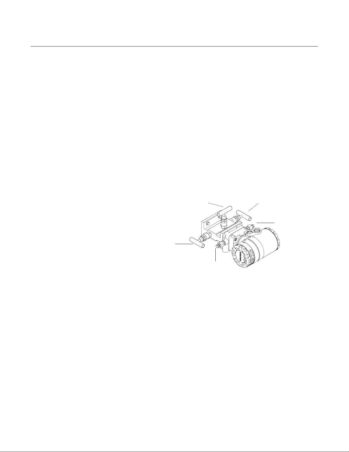
Instrument Manifolds Figure 2-4 identifies the valves on a 3-valve manifold. Table 2-1 explains the
purpose of these valves.
An instrument manifold is recommended for all installations. A manifold allows
an operator to equalize the pressures prior to the zero calibration of the
electronics as well as to isolate the electronics from the rest of the system
without disconnecting the impulse piping.
Figure 2-4. Valve Identification
for a 3-Valve Manifold
NOTE
Some recently-designed instrument manifolds have a single valve actuator,
but cannot perform all of the functions available on standard 5-valve units.
Check with the manufacturer to verify the functions that a particular manifold
can perform. In place of a manifold, individual valves may be arranged to
provide the necessary isolation and equalization functions.
To P H To P L
ME
MH
2
1
ML
DVLDVH
8900_8900_35A
2-5

Rosemount 285
Table 2-1. Description of
Impulse Valves and
Components
Reference Manual
00809-0100-4028, Rev AA
October 2005
Name Description Purpose
Manifold and Impulse Pipe Valves
PH Primary Sensor – High Pressure Isolates the flowmeter sensor from the
PL Primary Sensor – Low Pressure
DVH Drain/Vent Valve – High Pressure Drains (for gas service) or vents (for
DVL Drain/Vent Valve – Low Pressure
MH Manifold – High Pressure Isolates high side or low side pressure
ML Manifold – Low Pressure
Components
1 Electronics Reads Differential Pressure Isolates
2 Manifold
3 Vent Chambers Collects gases in liquid applications.
4 Condensate Chamber Collects condensate in gas
impulse piping system
liquid or steam service) the DP
electronics chambers
from the process.
and equalizes electronics.
applications.
Straight Run
Requirements
Use the following to aid in determining the straight run requirements
NOTE
• If longer lengths of straight run are available, position the mounting
such that 80% of the run is upstream and 20% is downstream.
• Straightening vanes may be used to reduce the required straight run
length.
• Row 5 in Table 2-2 is to be used if a “through type” valve will remain
open. Row 6 in Table 2-2 applies to gate, globe, plug, and other
throttling valves that are partially opened, as well as control valves.
2-6

Rosemount 285
Table 2-2. Straight Run
Requirements
Reference Manual
00809-0100-4028, Rev AA
October 2005
Upstream Dimensions
Without Vanes With Vanes
In
Out of
Plane
Plane
A
A
A’ C C’
1
8
10
—
—
—
—
8
—
4
4
Dimensions
Downstream
4
4
2
3
4
11
—
23
—
12
—
16
—
28
—
12
—
—
—
8
—
—
8
—
—
8
—
4
—
4
—
4
4
4
4
4
4
4
4
4
4
2-7

Rosemount 285
1
1
Reference Manual
00809-0100-4028, Rev AA
October 2005
Figure 2-5. Mounting
Configuration
Table 1. Minimum straight duct requirements for the 285 Annubar
H
W
H
W
DAMPER
15W
15W
7W
7W
7W
2W
2W
H
2W
W
2W
W
2W
W
Upstream Length Downstream Length
285/15-490028-901
285/15-490029-901
285/15-490030-90
H
285/15-490031-90
H
285/15-490032-901
7W 2W
7W 2W
15W 2W
7W 2W
15W 2W
Direct Mount Horizontal Pipes
Liquid or Steam Applications
Due to the possibility of air getting trapped in the probe, the sensor should
be located according to Figure 2-6 for liquid or steam applications. The
area between 0° and 30° angle should not be used unless full bleeding of
air from the probe is possible.
For liquid applications, mount the side drain/vent valve upward to allow the
gases to vent.
In steam applications, fill the lines with water to prevent the steam from
contacting the electronics. Condensate chambers are not required
because the volumetric displacement of the electronics is negligible.
Air and Gas Applications
Figure 2-6 illustrates the recommended location of the flowmeter in air or
gas applications. The sensor should be located on the upper half of the
pipe, at least 30° above the horizontal line.
For air and gas applications, mount the drain/vent valve downward to allow
liquid to drain.
2-8

Rosemount 285
Reference Manual
00809-0100-4028, Rev AA
October 2005
Figure 2-6. Horizontal Pipe
Applications
Liquid and Steam Gas
120
30°
120°
30°
30
Vertical Pipes
Liquid, Steam, Air, and Gas Applications
Figure 2-7 illustrates the recommended location of the flowmeter in liquid,
air, or gas applications.
The sensor can be installed in any position around the circumference of
the pipe, provided the vents are positioned properly for bleeding or
venting. Vertical pipe installations require more frequent bleeding or
venting, depending on the location.
30
15-490000-901, 15-490001-901
Figure 2-7. Vertical Pipe
Applications
Liquid and Steam Gas
Remote Mount Valves and Fittings
Throughout the remote mounting process:
• Use only valves, fittings, and pipe thread sealant compounds that are
rated for the service pipeline design pressure and temperature as
specified in Appendix A: Reference Data.
• Verify that all connections are tight and that all instrument valves are
fully closed.
• Verify that the sensor probe is properly oriented for the intended type of
service: liquid, gas or steam (see “Direct Mount” on page 2-8 and
“Remote Mount” on page 2-9).
360
FLOW
FLOW
360
15-490002-901,
15-490003-901
2-9

Rosemount 285
Reference Manual
00809-0100-4028, Rev AA
October 2005
Impulse Piping
Impulse piping connects remote mounted electronics to the sensor.
Temperatures in excess of 250 °F (121 °C) at the electronics will damage
electronics components; impulse piping allows service flow temperatures to
decrease to a point where the electronics is no longer vulnerable.
The following restrictions and recommendations apply to impulse piping
location.
• Piping used to connect the sensor probe and electronics must be rated
for continuous operation at the pipeline-designed pressure and
temperature
• Impulse piping that runs horizontally must slope at least 1–in. per foot
(83mm/m).
It must slope downwards (toward the electronics) for liquid and steam
applications.
It must slope up (away from the electronics) for gas applications.
• For applications where the pipeline temperature is below 250 °F (121
°C), the impulse piping should be as short as possible to minimize flow
temperature changes. Insulation may be required.
• For applications where pipeline temperature is above 250 °F (121 °C),
the impulse piping should have a minimum length of 1-ft. (0.30 m) for
every 100 °F (38 °C) over 250 °F (121 °C), which is the maximum
operating electronics temperature. Impulse piping must be uninsulated
to reduce fluid temperature. All threaded connections should be
checked after the system comes up to temperature, because
connections may be loosened by the expansion and contraction
caused by temperature changes.
1
• A minimum of
tubing with a wall thickness of at least 0.035-in. (0.9 mm) is
recommended.
• Outdoor installations for liquid, saturated gas, or steam service may
require insulation and heat tracing to prevent freezing.
• For installations where the electronics are more than 6-ft. (1.8m) from
the sensor probe, the high and low impulse piping must be run together
to maintain equal temperature. They must be supported to prevent
sagging and vibration.
• Threaded pipe fittings are not recommended because they create voids
where air can become entrapped and have more possibilities for
leakage.
• Run impulse piping in protected areas or against walls or ceilings. If the
impulse piping is run across the floor, ensure that it is protected with
coverings or kick plates. Do not locate the impulse piping near high
temperature piping or equipment.
• Use an appropriate pipe sealing compound rated for the service
temperature on all threaded connections. When making threaded
connections between stainless steel fittings, Loctite® PST® Sealant is
recommended.
/4-in. (6.35 mm) outer diameter (OD) stainless steel
2-10

Rosemount 285
Horizontal Pipes Liquid or Steam Applications
Due to the possibility of air getting trapped in the probe, the sensor should be
located according to Figures 2-8 and 2-10 for liquid or steam applications.
The area between 0° and 30° angle should not be used unless full bleeding of
air from the probe is possible.
In steam applications, fill the lines with water to prevent the steam from
contacting the electronics. Condensate chambers are not required because
the volumetric displacement of the electronics is negligible.
Air and Gas Applications
Figure 2-9 illustrates the recommended location of the flowmeter in air or gas
applications. The sensor should be located on the upper half of the pipe, at
least 30° above the horizontal line.
Figure 2-8. Liquid Service
Reference Manual
00809-0100-4028, Rev AA
October 2005
Figure 2-9. Gas Service
30°
30
30°
120°
120
30
2-11

Rosemount 285
Figure 2-10. Steam Service
Reference Manual
00809-0100-4028, Rev AA
October 2005
30°
120°
30°
INSTALLATION This manual contains the horizontal and vertical installation procedures for the
Pak-Lok and Duct Mount Annubar models.
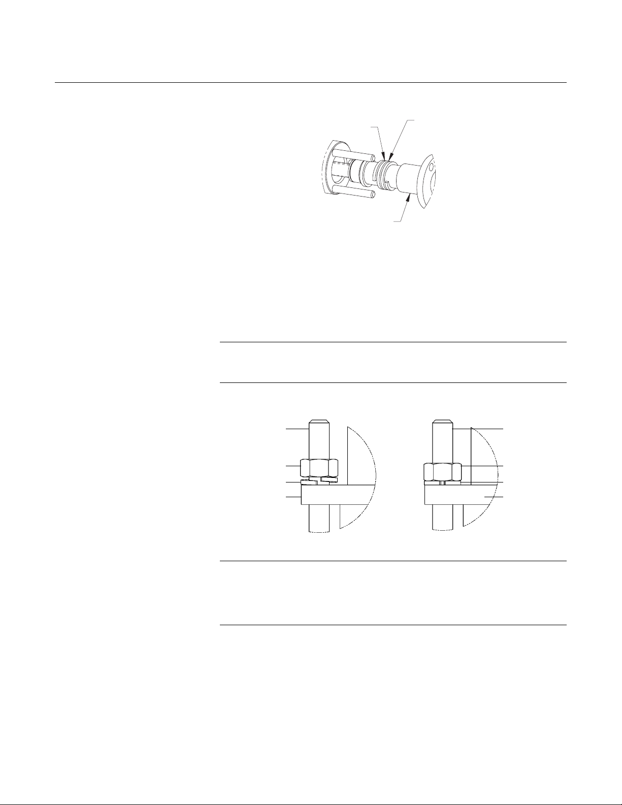
Pak-Lok Model Figure 2-11 identifies the components of the Pak-Lok assembly.
Figure 2-11. Components
Direct Mount Electronics
Connection with Valves
One Piece
Nuts & Washers
Compression
Plate
String Packing
Follower
Studs
285 Annubar
Pak-Lok Body
Threaded Coupling
Step 1: Determine the Proper Orientation
Please refer to “Mounting” on page 2-4 for straight run requirements and
orientation information.
Step 2: Drill a Hole into the Pipe
Follow the steps below to drill the hole in the pipe.
1. Depressurize and drain the pipe.
2. From the previous steps, select the location to drill the hole.
3. Determine the diameter of the hole to be drilled according to the
specifications in Table 2-3 and drill the hole. Do not torch cut the
hole.
15-490023-901a.eps
2-12

Rosemount 285
Figure 2-12. Drill Hole into Pipe
Table 2-3. Sensor Size / Hole
Reference Manual
00809-0100-4028, Rev AA
October 2005
Note: Drill the appropriate diameter
hole through the pipe wall.
Drill the hole 180 degrees
from the first hole for
opposite-side support
models.
Sensor Width Sensor Size Hole Diameter
3
0.590-in. (14.99 mm) 1
1.060-in. (26.92 mm) 2 15/16-in. (34 mm) + 1/16-in. (1 mm)
4. If opposite-side support coupling is supplied, a second identically
sized hole must be drilled opposite the first hole so that the sensor
can pass completely through the pipe. (To determine a opposite-side
support model, measure the distance from the tip of the first slot or
hole. If the distance is greater than 1-in. (25.4 mm), it is the
opposite-side model.) To drill the second hole, follow these steps:
a. Measure the pipe circumference with a pipe tape, soft wire, or
string (for the most accurate measurement the pipe tape needs to
be perpendicular to the axis of flow).
b. Divide the measured circumference by two to determine the
location of the second hole.
c. Rewrap the pipe tape, soft wire, or string from the center of the first
hole. Then, using the number calculated in the preceding step,
mark the center of what will become the second hole.
d. Using the diameter determined from Table 2-3, drill the hole into
the pipe with a hole saw or drill. Do not torch cut the hole.
e. Deburr the drilled hole(s) on the inside of the pipe.
/4-in. (19 mm) + 1/32-in (1 mm)
– 0.00
– 0.00
8900-8900_15A.EPS
2-13
Step 3: Weld the Mounting Hardware
1. Center the weld fitting over the mounting hole, gap 1/16-in. (1.5 mm)
and place four 1/4-in. (6-mm) tack welds at 90° increments. Check
alignment of the weld fitting both parallel and perpendicular to the
axis of flow. If alignment of mounting is within tolerances (see
Figure 1-1), finish weld per local codes. If alignment is outside of
specified tolerance make adjustments prior to finish weld.

Rosemount 285
Figure 2-13. Alignment
Reference Manual
00809-0100-4028, Rev AA
October 2005
LMH
Tack
Welds
(1) LMH values are as follows:
Sensor Size 1: 2.89-in. (73 mm)
Sensor Size 2: 3.92-in. (100 mm)
NOTE
To avoid serious burns, allow the mounting hardware to cool before
continuing.
Step 4: Insert into the Pipe
After the mounting hardware has cooled, use the following steps for
installation.
15-490024A-901.EPS
1. Apply appropriate thread sealant to Thread Pak-Lok body, insert into
weld fitting and tighten.
2. Thread studs into the Pak-Lok body.
3. To ensure that the flowmeter contacts the opposite side wall, mark the
tip of the sensor with a marker.
4. Rotating the flowmeter back and forth, insert the flowmeter into the
Pak-Lok body until the sensor tip contacts the pipe wall (or support
plug).
5. Remove the flowmeter.
6. Verify that the sensor tip made contact with the pipe wall by removing
from the pipe and ensuring that some of the marker has been rubbed
off. If the tip did not touch the wall, verify pipe dimensions and the
height of mounting body from the OD of the pipe and re-insert.
7. Re-insert the flowmeter into the Pak-Lok body and install the string
packing ring on the sensor between the lock ring and the packing
follower. Do not damage the string packing.
8. Push the packing ring into the Pak-Lok body and against the weld
lock ring.
2-14
Rosemount 285
A
Figure 2-14. Packing Ring Detail
Reference Manual
00809-0100-4028, Rev AA
October 2005
(3) THREE FULL
TURNS
NNUBAR ASSEMBLY
9. Tighten the nuts onto the studs:
Place the included split-ring lock washer between each of the nuts
and the compression plate. Give each nut one half (1/2) turn in
succession until the split-ring lock washer is flat between the nut and
the compression plate. Inspect the unit for leakage; if any exists,
tighten the nuts in one-quarter (1/4) turn increments until there is no
leakage.
PACKING FROM
ENVELOPE
Figure 2-15. Split-Ring Lock
Washer Orientation
NOTE
On sensor size (1), failure to use the split-ring lock washers, improper washer
orientation, or over-tightening the nuts may result in damage to the flowmeter.
Stud
Nut
Split ring
lock washer
Compression
Plate
Before Tightening After Tightening
Stud
Nut
Split ring
lock washer
Compression
Plate
NOTE
Pak-Lok sealing mechanisms generate significant force at the point where the
sensor contacts the opposite pipe wall. Caution needs to be exercised on
thin-walled piping (ANSI Schedule 10 and below) to avoid damage to the
pipe.
28-490000_943A01A
2-15

Rosemount 285
Reference Manual
00809-0100-4028, Rev AA
October 2005
Step 5: Mount the Transmitter
Direct Mount Head
With Valves
• Place Teflon (PTFE) O-rings into grooves on the face of head.
• Align the high side of the transmitter to the high side of the probe
• (“Hi” is stamped on the side of the head) and install.
• Tighten the nuts in a cross pattern to 400 in•lb (45 N•m).
Without Valves
• Place Teflon (PTFE) O-rings into grooves on the face of head.
• Orient the equalizer valve or valves so they are easily accessible.
Install manifold with the smooth face mating to the face of the head.
Tighten in cross pattern to a torque of 400 in•lb (45 N•m).
• Place Teflon (PTFE) O-rings into grooves on the face of the manifold.
• Align the high side of the transmitter to the high side of the probe
• (“Hi” is stamped on the side of the head) and install.
• Tighten the nuts in a cross pattern to 400 in•lb (45 N•m).
Figure 2-16.
Remote Mount Head – temperatures below 250 °F (121 °C)
See “Remote Mount” on page 2-9 for more information.
Liquid Applications Gas Applications
Secure the electronics below the sensor to
ensure that air will not be introduced into the
impulse piping or the electronics.
Secure the electronics above the sensor to
prevent condensable liquids from collecting in
the impulse piping and the DP cell.
28_490000_932A, 931A
2-16

Rosemount 285
Figure 2-17. Liquid or Steam
Applications
Reference Manual
00809-0100-4028, Rev AA
October 2005
Remote Mount Head – temperature above 250 °F (121 °C)
Horizontal Line Vertical Line
28_490000_933A01A, 934A01A
2-17

Reference Manual
00809-0100-4028, Rev AA
Rosemount 285
October 2005
Duct Model Figure 2-18 identifies the components of the Duct Model assembly.
Figure 2-18. Components
Gasket or Sealant
#12 Sheet
Metal Screws
for High Temperature
Nut
Lock Washer
Figure 2-19. Drill Hole into Duct
Duct
Annubar
Stud
Step 1: Determine the Proper Orientation
Please refer to “Mounting” on page 2-4 for straight run requirements and
orientation information.
Step 2: Drill a Hole into the Duct
Follow the steps below to drill the hole in the duct.
1. Depressurize and drain the duct.
2. From the previous steps, select the location to drill the hole.
3. Determine the diameter of the hole to be drilled according to the
specifications in Table 2-4 and drill the hole with a hole saw or a drill.
Do not torch cut the hole.
D
D
B
B
Table 2-4. Installation
dimensions
2-18
C
Annubar Model Number B D
285xxxxxxxD1x1x 0.75 in (19.05 mm) 0.38 in (9.65 mm)
285xxxxxxxD1x2x 1.31 in (33.27 mm) 0.38 in (9.65 mm)
285xxxxxxxD2x1x 0.75 in (19.05 mm) not applicable
285xxxxxxxD2x2x 1.31 in (33.27 mm) not applicable
C
285/15-490014-901,
15-490035-901.EPS

Rosemount 285
Table 2-5. Hole drill size for #12
self-tapping screws
(C-dimension) inches (mm)
Reference Manual
00809-0100-4028, Rev AA
October 2005
Hole Required
Duct Wall Thickness Hole Size Drill Size
less than 0.036 in (0.91 mm) 0.166 in (4.2 mm) #19
0.048 in (1.22 mm) 0.169 in (4.3 mm) #18
0.060 in (1.52 mm) 0.177 in (4.5 mm) #16
0.075 in (1.91 mm) 0.182 in (4.6 mm) #14
0.105 in (2.67 mm) 0.185 in (4.7 mm) #13
0.125 in (3.18 mm) 0.196 in (5.0 mm) #9
0.135 in (3.43 mm) 0.196 in (5.0 mm) #9
0.164 in (4.17 mm) 0.201 in (5.1 mm) #7
4. If opposite-side support is supplied, a second hole must be drilled
opposite the first hole so that the sensor support can pass through the
pipe. To drill the second hole, follow these steps:
a. Mark the mounting location of the Annubar, locating it along the
center line of the rectangular duct or anywhere on the
circumference of a round duct. Mark horizontal and vertical center
lines through the mounting location.
b. For duct mount Annubars without compression fitting (threaded
stud welded to tip of sensor), extend the center line to the opposite
duct wall (or 180° around a circular duct).
c. Rewrap the pipe tape, soft wire, or string from the center of the first
hole. Then, using the number calculated in the preceding step,
mark the center of what will become the second hole.
d. Using the diameter determined from Table 2-4, drill the hole into
the pipe with a hole saw or drill. Do not torch cut the hole.
5. Deburr the drilled hole or holes on the inside of the pipe.
Figure 2-20. Fit-up Check for
Annubar with Opposite Side
Support
Step 3: Assemble and check Fit-Up
1. Measure the Annubar Primary Element from the duct plate to the end
of the probe shape.
2. Measure the duct from the far inside wall to the close outside wall and
1
/16-in. (1.5 mm).
add
3. Compare the numbers in steps 1 and 2.
Small discrepancies can be compensated for with the fit-up of the mounting
hardware. Large discrepancies may cause installation problems or error.
2-19

Rosemount 285
A
Reference Manual
00809-0100-4028, Rev AA
October 2005
Step 4: Insert into Duct
Duct-Mount without Compression Fitting (Annubar type D1)
1. Place the gasket over the end of the probe and push it up against the
mounting flange. Alternatively, a high-temperature gasket sealant
may be used.
2. Insert the end of the Annubar through the mounting hole, and push it
through the duct until the threaded stud protrudes through the hole on
the opposite side of the duct.
Figure 2-21.
Figure 2-22.
GASKET OR SEALANT
5/16-18 STUD
ANNUBAR
FOR HIGH TEMPERATURE
5/16-18 STUD
NNUBAR
GASKET OR SEALANT
FOR HIGH TEMPERATURE
3. Push the flange and gasket flush against the duct wall; align the flow
arrow in the direction of flow and fasten the flange to the duct using
the #12 sheet metal screws provided.
285/15-490015-901, 15-490036-901
STUD
#12 SHEET METAL SCREWS
285/15-490016-901,15-490017-901
2-20

Rosemount 285
R
Reference Manual
00809-0100-4028, Rev AA
October 2005
STUD
#12 SHEET
METAL SCREWS
4. On the opposite side of the duct, place the 5/16-in. lock washer over
the stud, screw on the
pressure in the duct, it may be necessary to add some high
temperature gasket sealant where the stud protrudes through the
duct wall.
5
/16 nut, and tighten. Depending on the
285/15-490037-901,15-490038-901
Figure 2-23.
Figure 2-24.
NUT
DUCT
STUD
LOCK WASHER
ANNUBAR
DUCT
STUD
NUT
LOCK WASHER
ANNUBA
Duct Mount With Compression Fitting (Annubar type D2)
1. Place gasket against the mounting flange. Alternatively, a
high-temperature gasket sealant may be used.
2. Push the flange and gasket flush against the duct wall, and fasten the
flange to the duct using the #12 sheet metal screws provided.
GASKET OR SEALANT
FOR HIGH TEMPERATURE
DUCT MOUNT PLATE
WITH THREADED
COUPLING
285/15-490018-901, /15-490039-901
2-21
#12 SHEET
METAL SCREWS
285/15-490022-901
3. Remove the packing gland from the Annubar, and thread it into the
threaded coupling, using teflon tape or pipe sealant.

Rosemount 285
A
Figure 2-25.
Figure 2-26.
Reference Manual
00809-0100-4028, Rev AA
October 2005
THREADED
COUPLING
PACKING GLAND
TEFLON TAPE OR
PIPE SEALANT
4. Remove the packing from the envelope and wrap it around the
Annubar three full turns. Insert the Annubar into the mounting until the
packing is completely contained within the glad, and the tip of the
Annubar is contacting the opposite side of the duct wall. Place the
lock washers over the studs on the packing gland and hand tighten
the nuts.
(3) THREE FULL
TURNS
PACKING FROM
ENVELOPE
285/ 15-490040-901
NNUBAR ASSEMBLY
5. Align the flow arrow on the Annubar with the flow direction in the duct
and tighten the nuts on the packing.
NOTE
Do not over tighten the packing, as this can lead to deforming the opposite
wall of the duct.
6. Observe the opposite side of the duct and ensure that the ducting has
not deformed.
Step 5: Mount the Transmitter
Direct Mount Head
With Valves
1. Place Teflon (PTFE) O-rings into grooves on the face of head.
2. Align the high side of the transmitter to the high side of the probe
(“Hi” is stamped on the side of the head) and install.
3. Tighten the nuts in a cross pattern to 400 in•lb (45 N•m).
285/ 15-490041-901
2-22

Rosemount 285
Reference Manual
00809-0100-4028, Rev AA
October 2005
Without Valves
1. Place Teflon (PTFE) O-rings into grooves on the face of head.
2. Orient the equalizer valve or valves so they are easily accessible.
Install manifold with the smooth face mating to the face of the head.
Tighten in cross pattern to a torque of 400 in•lb (45 N•m).
3. Place Teflon (PTFE) O-rings into grooves on the face of the manifold.
4. Align the high side of the transmitter to the high side of the probe
(“Hi” is stamped on the side of the head) and install.
5. Tighten the nuts in a cross pattern to 400 in•lb (45 N•m).
Remote Mount Head
See “Remote Mount” on page 2-9 for more information.
Gas Applications
Secure the electronics above the sensor to prevent condensable liquids from collecting in the
impulse piping and the DP cell.
2-23

Rosemount 285
Reference Manual
00809-0100-4028, Rev AA
October 2005
2-24

Reference Manual
00809-0100-4028, Rev AA
October 2005
Section 3 Commissioning
Safety Messages . . . . . . . . . . . . . . . . . . . . . . . . . . . . . . . . . page 3-5
Commissioning on the Bench . . . . . . . . . . . . . . . . . . . . . . page 3-5
Commissioning the 285 with the 2024 transmitter . . . . . page 3-6
COMMISIONING THE 951 TRANSMITTER
Rosemount 285
Step 1: Mount the
Transmitter
Gas Flow Applications
• Non-corrosive, non-combustible, and non-condensing gas only.
•Restrain
• Process connections should be mounted horizontally or vertically for best performance.
• Pressure maximum may be limited by connector.
Figure 1. Rosemount 951 Transmitter
Figure 2. Rosemount 951 Transmitter Flush Mount
5
/8 Hex when torquing process adaptors or connections.
-
+
H
L
Power ±signal
4-20 mA Connection
* or factory installed adaptors
Process Connections
1
/8 inch NPT fitting *
H = High Pressure
L = Low Pressure
Bracket Screws
951/951_01ae.eps
www.rosemount.com
Figure 3. Rosemount 951 Transmitter Panel Mount
Note: Screws provided by
installer depending on
surface.
951/951_02a.eps

Rosemount 285
Figure 4. Rosemount 951 Transmitter Side Mount
Note: Screws provided by
installer depending on
surface.
951/951_04ab.eps
Note: Screws
provided by installer
depending on surface.
951/951_03a.eps
Reference Manual
00809-0100-4028, Rev AA
October 2005
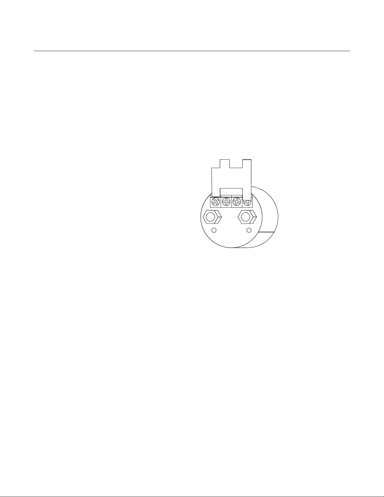
Step 2: Connect Wiring
and Power Up
1. Connect the positive lead to the "+" terminal, and the negative lead to the "–" terminal.
NOTE
Twisted pairs yield best results; shielded signal wiring is not necessary. Use 24 AWG or larger
wire and do not exceed 5,000 feet (1,500 meters).
Figure 5 shows the wiring connections necessary to power a Rosemount 951 and enable
communications with a hand-held HART communicator.
Figure 5. Rosemount 951 Wiring
-
+
L
H
Rosemount
951
RL ≥ 250 Ω
HART
Communicator
Power
Supply
951/951_05ab.eps
Power Supply
The dc power supply should provide power with less than two percent ripple. The total resistance
load is the sum of the resistance of the signal leads and the load resistance of the controller,
indicator, and related pieces.
Figure 6. Power Supply Load Limitations, 4–20 mA Transmitters
3-2

Reference Manual
00809-0100-4028, Rev AA
October 2005
Max. Loop Resistance = 43.5 ⫻ (Power Supply Voltage – 10.5)
1388
1109
1000
500
Load (Ohms)
Operating Region
Rosemount 285
Step 3: Configure the
Transmitter
0
10.5
Communication requires a minimum loop resistance of 250 ohms.
20
Voltage (V dc)
30
951-0103c
40
36
A check (⻫) indicates the basic configuration parameters. At minimum, these parameters should
be verified as part of the configuration and startup procedure if a HART Communicator is used.
Function HART Fast Key Sequence
Alarm Level Config. 1, 4, 2, 7, 6
Alarm and Saturation Levels 1, 4, 2, 7
Analog Output Alarm Direction 1, 4, 2, 7, 1
Analog Output Trim 1, 2, 3, 2
Burst Mode On/Off 1, 4, 3, 3, 3
Burst Options 1, 4, 3, 3, 4
⻫ Damping 1, 3, 6
Date 1, 3, 4, 1
Descriptor 1, 3, 4, 2
Digital To Analog Trim (4-20 mA Output) 1, 2, 3, 2, 1
Field Device Information 1, 4, 4, 1
Loop Test 1, 2, 2
Lower Sensor Trim 1, 2, 3, 3, 2
Message 1, 3, 4, 3
Number of Requested Preambles 1, 4, 3, 3, 2
Poll Address 1, 4, 3, 3, 1
Poll a Multidropped Transmitter Left Arrow, 4, 1, 1
Rerange- Keypad Input 1, 2, 3, 1, 1
Saturation Level Config. 1, 4, 2, 7, 7
Scaled D/A Trim (4–20 mA Output) 1, 2, 3, 2, 2
Self Test (Transmitter) 1, 2, 1, 1
Sensor Information 1, 4, 4, 2
Sensor Temperature 1, 1, 4
Sensor Trim 1, 2, 3, 3
Sensor Trim Points 1, 2, 3, 3, 5
Status 1, 2, 1, 2
⻫ Tag 1, 3, 1
⻫ Transfer Function (Setting Output Type) 1, 3, 5
⻫ Units (Process Variable) 1, 3, 2
Upper Sensor Trim 1, 2, 3, 3, 3
Zero Trim 1, 2, 3, 3, 1
Step 4: Trim the
Transmitter
NOTE
Transmitters are shipped from Rosemount Inc. fully calibrated per request or by the factory
default of full scale (span = upper range limit.)
Zero Trim
A zero trim is a single-point adjustment used for compensating mounting position. When
performing a zero trim, ensure that the equalizing valve is open (if present).
If zero offset is less than 3% of true zero, follow the “Using the 275/375 HART Communicator”
instructions below to perform a zero trim. If zero offset is greater than 3% of true zero, follow the
“Local Re-ranging and Trim” instructions below to rerange.
3-3

Rosemount 285
Reference Manual
00809-0100-4028, Rev AA
October 2005
Using the 275/375 HART Communicator
HART Fast Keys Steps
1, 2, 3, 3, 1
Local Re-ranging and Trim
Both 4 and 20 mA points can be adjusted at the transmitter to a desired zero and full scale using
the adjustment key or LCD adjustment buttons while powered.
Caution: Make sure no high voltage is present.
NOTE:
More comprehensive adjustment is possible with a HART Communicator.
Zero - 4 mA point
Without an LCD meter
1. Using an appropriate quality pressure source, apply a pressure equivalent to the desired
lower range value to the transmitter. If zero, make sure the High (H) and Low (L) pressure
ports are at the same pressure.
2. Touch the key to the terminals, as shown in Figure 7, for at least two seconds but no longer
than ten seconds.
With an LCD meter
1. Using an appropriate quality pressure source, apply a pressure equivalent to the desired
lower range value to the transmitter. If zero, make sure the High (H) and Low (L) pressure
ports are at the same pressure.
2. Push and hold the zero LCD adjustment button for at least two seconds but no longer than ten
seconds.
Figure 7. Zero 4 mA
1. Equalize or vent the transmitter and connect HART communicator.
2. At the menu, input the HART Fast Key sequence.
3. Follow the commands to perform a zero trim.
+
Span 20 mA
Zero 4 mA
+
-
+
-
H
L
951/951_01ac.eps
Span - 20 mA point
Without an LCD meter
1. Using an appropriate quality pressure source, apply a pressure equivalent to the desired
upper range value.
2. Touch the key to the terminals, as shown in Figure 8, for at least two seconds but no longer
than ten seconds.
With an LCD meter
1. Using an appropriate quality pressure source, apply a pressure equivalent to the desired
upper range value.
2. Push and hold the span LCD adjustment button for at least two seconds but no longer than
ten seconds.
NOTE:
The Span is maintained when the 4 mA point is set. The span changes only when the 20 mA point
is set. Changing the span should not be required as a result of installation.
Figure 8. Span 20 mA
3-4

Reference Manual
00809-0100-4028, Rev AA
Rosemount 285
-
+
Span 20 mA
-
+
+
-
H
Zero 4 mA
L
951/951_01ad.eps
October 2005
SAFETY MESSAGES Instructions and procedures in this section may require special precautions to
ensure the safety of the personnel performing the operations. Please refer to
the following safety messages before performing any operation in this section.
COMMISSIONING ON THE BENCH
Explosions could result in death or serious injury:
• Do not remove the transmitter cover in explosive atmospheres when the circuit is
live.
• Before connecting a Rosemount HART Communicator in an explosive
atmosphere, make sure the instruments in the loop are installed in accordance
with intrinsically safe or non-incendive field wiring practices.
• Verify that the operating atmosphere of the transmitter is consistent with the
appropriate hazardous locations certifications.
• Both transmitter covers must be fully engaged to meet explosion-proof
requirements.
Failure to follow these installation guidelines could result in death or serious injury:
• Make sure only qualified personnel perform the installation.
• If the line is pressurized, serious injury or death could occur by opening valves.
Commissioning consists of testing the flowmeter, testing the loop, and
verifying the flowmeter configuration data. The flowmeter can be
commissioned either before (on the bench) or after (in the field) installation.
Commissioning on the bench ensures that all flowmeter components are in
good working order and acquaints the user with the operation of the device.
To avoid exposing the flowmeter electronics to the environment after
installation, set the failure mode and flowmeter security switches while
commissioning the flowmeter on the bench.
Figure 2-4 on page 2-5 identifies the valves on a 3-valve manifold. Table 2-1
on page 2-6 explains the purpose of these valves.
3-5
Complete the following tasks before beginning the commissioning procedure:

Rosemount 285
Reference Manual
00809-0100-4028, Rev AA
October 2005
1. Connect an appropriate readout instrument so the differential
pressure signal can be monitored.
2. Identify the manifold equalizer valves by their ME prefix.
3-valve manifolds have one equalizer valve, ME.
3. Close all valves before commissioning the system.
COMMISSIONING THE
For complete 2024 transmitter information, refer to manual 00809-0100-4592.
285 WITH THE 2024
TRANSMITTER
Direct Mount Liquid Service
1. Open the high and low manifold valves MH and ML.
2. Open the equalizer valve ME.
3. Open the drain/vent valves on the electronics DVL and DVH; bleed
until no air is apparent in the liquid.
4. Close both drain/vent valves DVL and DVH.
5. Close the high and low manifold valves MH and ML.
6. Check the electronics zero by noting the output—this is called a wet
zero. If the signal reads outside of the range 3.98 mA to 4.02 mA, air
is probably still in the system; repeat step 2, and trim zero if
necessary.
7. Open the high and low manifold valves ML and MH.
8. Close equalizer valve ME. The system is now operational.
Liquid Service 3-Valve Manifold
Dry Zero
1. Prior to commissioning the flowmeter a dry zero should be performed
to eliminate any positional effects to the transmitter.
2. Keeping both the high and low main valves closed MH and ML open
the equalizer valve ME.
3. Perform a zero trim
4. Check the electronics zero by noting the output. If the signal reads
outside of the range 3.98 mA to 4.02 mA then repeat step 3 and 4.
3-6
Rosemount 285
Reference Manual
00809-0100-4028, Rev AA
October 2005
Wet Zero
1. Open the High and Low manifold valves MH and ML.
2. Open the Equalizer valve ME.
3. Open the drain/vent valves on the electronics DVH and DVL; bleed
until no air is apparent in the liquid.
4. Close both drain/vent valve DVH and DVL.
5. Close the High side valve MH.
6. Check the electronics zero by noting the output. If the signal reads
outside of the range 3.98 mA to 4.02 mA then perform a zero trim.
7. Check the electronics zero by noting the output. If the signal reads
outside of the range 3.98 mA to 4.02 mA then repeat steps 1 - 6.
8. Close the Equalizer valve ME.
9. Open the High side valve MH and ensure that the Low side valve ML
is open.
10. The system is now operational.
Figure 3-1. Valve Identification
for Direct Mounted Annubar
model in Liquid Service
ME
ML
DVL
MH
DVH
Gas Service
1. Ensure that the pipe is pressurized.
2. Open both high and low side main valves MH and ML.
3. Open equalization valve ME.
4. Open the drain valves DVL and DVH on the electronics to ensure that
no liquid is present.
5. Close drain valves DVL and DVH.
6. Check the electronics for the 4 mA signal. Trim zero if necessary.
7. Close the equalizer valve ME. The system is now operational.
2024/2024A24A.EPS
3-7
Rosemount 285
Reference Manual
00809-0100-4028, Rev AA
October 2005
Gas Service 3-Valve Manifold
Dry Zero
1. Prior to commissioning the flowmeter a dry zero should be performed
to eliminate any positional effects to the transmitter.
2. Keeping both the high and low main valves closed MH and ML open
the equalizer valve ME.
3. Perform a zero trim.
4. Check the electronics zero by noting the output. If the signal reads
outside of the range 3.98 mA to 4.02 mA then repeat step 3.
-
+
Zero 4 mA
Span 20 mA
-
+
+
-
H
L
951/951_01ad.eps
Wet Zero
1. Open the High and Low manifold valves MH and ML.
2. Open the Equalizer valve ME.
3. Open the drain/vent valves on the electronics DVH and DVL; bleed to
ensure that no liquid is present.
4. Close both drain/vent valve DVH and DVL.
5. Close the High side valve MH.
6. Check the electronics zero by noting the output. If the signal reads
outside of the range 3.98 mA to 4.02 mA then perform a zero trim.
7. Check the electronics zero by noting the output. If the signal reads
outside of the range 3.98 mA to 4.02 mA then repeat steps 1 - 6.
8. Close the Equalizer valve ME.
9. Open the High side valve MH, ensure that the Low side valve ML is
open. The system is now operational.
3-8

Rosemount 285
Figure 3-2. Valve Identification
for Direct Mounted Model in Gas
Service
ML
ME
Reference Manual
00809-0100-4028, Rev AA
October 2005
MH
DVH
DVL
Steam Service
1. Ensure that the steam line is depressurized with no steam.
2. Check the electronics for a dry zero of 4 mA with no water loss.
3. Open the high and low main valves MH and ML and equalizer valve
ME.
4. Close low side vent DVL on the electronics.
5. Close the high MH for 30 seconds to force water to the ML side.
6. Re-open the MH valve.
7. Open low side vent DVL on the electronics until no air is observed.
8. Close the vent.
9. Close the hose connect valve.
10. Close both MH and ML.
11. Check the instrument zero by noting the electronics output. If the
signal reads outside of the range 3.98 mA to 4.02 mA, air is probably
still in the system; repeat this procedure from step 2, and trim sensor
if necessary.
12. Open MH and ML.
13. Close equalizer valve ME. The system is now operational.
2024/2024A24A.EPS
3-9

Rosemount 285
Reference Manual
00809-0100-4028, Rev AA
October 2005
3-Valve Steam No Flow
1. Prior to commissioning the flowmeter a dry zero should be performed
to eliminate any positional effects to the transmitter.
2. Keeping both the high and low main valves closed MH and ML open
the equalizer valve ME.
3. Perform a zero trim (see “Trim the Transmitter” on page 3-26).
4. Check the electronics zero by noting the output. If the signal reads
outside of the range 3.98 mA to 4.02 mA then repeat step 3.
5. Verify that the line is depressurized with no steam.
6. Open the High and Low main valves as well as the equalizer valve
MH, ML and ME.
7. Close low side vent DVL on the electronics.
8. Open the hose connect valve for a minimum of 30 seconds. Water will
flow through both the high and low chambers and into the pipe.
9. Close the high valve MH for 30 seconds to force water to the Low
side.
10. Re-open the main High valve MH.
11. Open the low side vent DVL on the electronics until no air is
observed.
12. Close the low side vent DVL.
13. Open both the high and low main valves MH and ML and close the
equalizer valve ME.
14. The sensor is ready for flow.
15. After flow has been started and allowed to reach operating conditions
a wet zero needs to be performed.
16. Using the drain/vent valves on the electronics DVH and DVL; burp
(carefully crack vents open and closed to ensure that no air is
present, this may need to be done more than one time.)
17. Close the High side main valve MH.
18. Open the Equalizer valve ME.
19. Check the electronics zero by noting the output. If the signal reads
outside of the range 3.98 mA to 4.02 mA then perform a zero trim.
20. After zero trim is done check the electronics zero by noting the output.
If the signal reads outside of the range 3.98 mA to 4.02 mA. Set
sensor back to flow by closing the Equalizer valve ME and opening
the High side valve MH. Repeat steps 14 - 17.
21. Close the Equalizer valve ME.
22. Open the High side valve MH, ensure that the Low side valve ML is
open. The system is now operational
Remote Mount Zero the Electronics
Before the electronics are exposed to line pressure, check the “zero”
calibration (or, “dry” zero) by using the following procedure.
3-10

Rosemount 285
Reference Manual
00809-0100-4028, Rev AA
October 2005
1. Open first the equalizer valve(s) MEL and MEH or ME.
2. Close valves MH and ML.
3. Read the Annubar output. It should read within the range 3.98 mA to
4.02 mA. If the output is outside of this range, zero trim.
Check for System Leaks
Check the system for leaks after installation is complete. A leak in a
differential pressure instrument system can produce a difference in pressure
that is larger than the signal itself.
Before the system is filled and/or commissioned, it is a simple matter to use
compressed air or another inert, compressed gas to check for leaks. The gas
pressure must be below the maximum allowed, but at least equal to the
normal operating pressure in order to reveal potential leaks. A typical
pressure used is 100 psig (690 kPa).
Before pressurizing the system, check for leaks by doing the following:
1. Open equalizer valve(s) MEH, MEL or ME to prevent overpressuring
the DP.
2. Close valves PH, PL (unless the piping system is also being
pressure-checked), MV, DVH, DVL.
If present, also close valves BH and BL or DH and DL.
3. Open valves MH and ML.
4. Install all appropriate tapped plugs.
5. Install a current meter to read the signal, if necessary.
Apply pressure at a convenient point on either the high or low side of the
system. Use a suitable leak detection solution and apply to all of the impulse
piping, valves, manifold, and connections. A leak is indicated by a continuous
stream of bubbles.
“Calibrate Out” Temperature Effects
NOTE
Do not begin this procedure until the system leak check has been completed
and all leaks have been fixed.
The flowmeter’s proportional output-to-flow ratio makes a true “zero”
calibration critical for producing accurate measurements. The “zero”
calibration procedure is affected by static pressure and ambient temperature,
but these effects can be removed by calibrating them “out.”
3-11

Rosemount 285
Reference Manual
00809-0100-4028, Rev AA
October 2005
The effect of static pressure is calibrated out by exposing the Annubar
electronics to the line pressure and performing a “zero” or wet calibration, as
described below. In order to calibrate out the effect of ambient temperature,
two aspects should be taken into consideration:
• The electronics should be located where the ambient temperature does
not change rapidly or vary by more than 10 to 15 °F (26 to 29 °C).
• When commissioning the electronics, the flowing fluid
(condensate/water for steam service) could bring the sensor to a
temperature significantly different than the temperature during normal
operations. In this situation, perform another “zero” calibration at least
60 minutes after the Annubar Primary Element has been
commissioned.
Although the above effects are relatively small, they significantly affect the
accuracy of the Annubar when used with low flows.
Periodic “zero” calibration and/or commissioning is recommended to maintain
the accuracy of Annubar. The frequency of this type of maintenance should
be established for each individual application.
Zero or Wet Calibration
Follow this procedure to obtain a true zero at static or “pipe” pressure:
1. Open ME and high side MH equalizer valves:
2. Close low side valve ML to prevent generating differential pressure.
Liquid Service below 250 °F (121 °C)
1. Ensure that primary instrument valves PH and PL are closed.
2. Open valves ME, ML, and MH.
3. Slowly open valve PL and then PH, which are the primary instrument
valves.
4. Open drain/vent valves DVL and DVH to bleed air out of system.
Bleed until no air is apparent in the liquid.
5. Close valves DVL and DVH.
3-12

Rosemount 285
Reference Manual
00809-0100-4028, Rev AA
October 2005
NOTE
For the alternate electronics location, open vent valves VH and VL and bleed
until no air is apparent in the liquid.
6. Slowly open vent valve MV to bleed out any entrapped air in manifold.
Bleed until no air is apparent in the liquid.
7. Close vent valve MV.
8. Gently tap the electronics body, valve manifold, and impulse piping
with a small wrench to dislodge any remaining entrapped air.
9. Repeat steps 2, 2A, and 3.
10. Close valve PH.
11. Check the Annubar zero by noting the electronics output — this is
called a wet zero. The electronics should indicate a zero DP
(Differential Pressure) signal. If the signal reads outside the range
3.98 mA to 4.02 mA, air is probably still in the system; repeat the
procedure from step 2. Trim zero if necessary.
12. Close ME equalizer valve(s).
13. Slowly open valve PH. The system is now operational.
Gas Service
1. For an impulse piping arrangement as shown in Figure (vertical pipe)
only, open primary instrument valves PH and PL.
2. Open drain valves DH and DL slowly to allow the condensate to
drain.
3. Close valves DH and DL.
4. Ensure that primary instrument valves PH and PL closed.
5. Open valves ME, ML and MH.
6. Slowly open valve PL, the primary high pressure instrument valve.
7. Check electronics zero by noting the electronics reading. The
electronics should indicate a “zero” DP signal. If the signal reads
outside of the range 3.98 mA to 4.02 mA, condensate may be in the
DP electronics or system; repeat the procedure from step 1 to remove
any condensate. A signal outside the range 3.98 mA to 4.02 mA can
also be caused by system leaks; check for leaks in system.
8. Close ME equalizer valve(s).
9. Slowly open valve PH. The system is now operational.
3-13

Rosemount 285
Reference Manual
00809-0100-4028, Rev AA
October 2005
Figure 3-3. Valve Identification
for Direct Mounted Annubar
model in Steam Service or
Liquid Service above 250 °F
(121 °C)
Valve Identification for Direct Mounted Annubar
ME
ML
DVL
MH
DVH
Steam Service or Liquid Service above 250 °F (121 °C)
1. Ensure that primary instrument valves PH and PL closed; ME, ML
and MH are closed; and DVL and DVH are closed.
2. Fill tees with water on each side until water overflows.
3. Open valves MH, ML and equalizer valve ME.
4. Open valves DVL and DVH.
5. Tap manifold until no air bubbles are visible.
6. Close both valves DVL and DVH.
7. Refill tees with water.
8. Gently tap electronics body, valve manifold, and impulse piping with a
small wrench to dislodge any remaining entrapped air.
9. Check Annubar zero by noting the electronics output — this is called
a wet zero. The electronics should indicate a “zero” DP signal. If the
signal reads outside of the range 3.98 mA to 4.02 mA, air is probably
still in the system; repeat this procedure from step 2. Trim zero if
necessary.
10. Close equalizer valve ME.
11. Replace plugs in tees.
12. Slowly open valves PH and PL. The system is now operational.
2024/2024A24A.EPS
3-14

Reference Manual
00809-0100-4028, Rev AA
October 2005
Rosemount 285
Section 4 Operation and Maintenance
Safety Messages . . . . . . . . . . . . . . . . . . . . . . . . . . . . . . . . . page 4-1
Troubleshooting . . . . . . . . . . . . . . . . . . . . . . . . . . . . . . . . . page 4-2
Disassembly . . . . . . . . . . . . . . . . . . . . . . . . . . . . . . . . . . . . page 4-3
SAFETY MESSAGES Procedures and instructions in this section may require special precautions to
ensure the safety of the personnel performing the operations. Information that
raises potential safety issues is indicated by a warning symbol ( ). Refer to
the following safety messages before performing an operation preceded by
this symbol.
Explosions can result in death or serious injury.
• Do not remove the instrument cover in explosive environments when the circuit is
live.
• Both transmitter covers must be fully engaged to meet explosion-proof
requirements.
• Before connecting a communicator in an explosive atmosphere, make sure the
instruments in the loop are installed in accordance with intrinsically safe or
nonincendive field wiring practices.
Electrical shock can result in death or serious injury.
• Avoid contact with the leads and the terminals.
www.rosemount.com

Reference Manual
00809-0100-4028, Rev AA
Rosemount 285
October 2005
TROUBLESHOOTING If a malfunction is suspected despite the absence of a diagnostic messages
on the communicator display, follow the procedures described below to verify
that the flowmeter hardware and process connections are in good working
order. Always approach the most likely and easiest-to-check conditions first.
Table 4-1. 285 Troubleshooting
Symptom Possible Cause Corrective Action
Questionable accuracy or
erroneous flow signal
Improper installation
System leaks
Contamination/plugging
Closed valve
Calibration
Connections (remote mount only)
Entrapped air (liquid applications)
Annubar Primary Element
misalignment
Opposite-side support duct
mount
Operating conditions
• Is the flow arrow pointed in the direction of the flow?
• Verify that the cross reservoirs are perfectly level with one another
• Is there sufficient straight run upstream and downstream of the
flowmeter?
• Check for leaks in instrument piping. Repair and seal all leaks.
• Remove the flowmeter and check for contamination.
• Verify that both manifold (MH & ML) valves are open. Verify that
vent, equalizer, and line valves are properly positioned per the “start
up procedure.”
• Is the calibration too high or low for the flow rate?
• Verify that the high side of the electronics is connected to the high
side of the flowmeter. Check the same for the low side.
• Are there uneven water legs caused by air entrapment in the
instrument connections? If so, bleed air.
• Misalignment of the flowmeter beyond 3 degrees will cause an
erroneous signal.
• If the flowmeter is an opposite-side support model, is it installed
through the pipe wall and into the nut?
• Are the operating conditions in compliance with those given at the
time the flowmeter was purchased? Check the flow calculation and
the fluid parameters for accuracy. Double-check pipe inside
diameter for proper sizing.
Spiking flow signal Two-phase flow
Spiking flow signal (Stream
Service)
Vibration of sensor or leakage at
Pak-Lok fitting
No response to changes in
applied flow
Low reading/high reading
Erratic reading for pressure
variable
4-2
Improper insulation (Vertical
pipes only)
Excessive vibration
Pak-Lok Compression nut(s)
loose
Note: For the multipoint flow calibrated flowmeter, refer to the
Handbook for corrections.
• The flowmeter is a head measurement device and will not
accurately measure a two-phase flow.
• Added insulation may be required to ensure that a phase change
occurs at the cross reservoirs.
• Check the impulse piping for vibration.
• Tighten compression nut(s) until condition is corrected and then ½
turn more only.
• Check test equipment
• Check impulse piping for blockage
• Check for disabled span adjustment
• Check electronics security switch
• Verify calibration settings (4 and 20 mA points)
• Contact factory for replacement
• Check impulse piping for blockage
• Check test equipment
• Contact factory for replacement
• Check impulse piping for blockage
• Check damping
• Check for EMF interference
• Contact factory for replacement

Reference Manual
00809-0100-4028, Rev AA
October 2005
DISASSEMBLY
Rosemount 285
Remove the Flowmeter
from Service
NOTE
Once you have determined a that flowmeter is inoperable, remove it from
service.
Be aware of the following:
• Isolate and vent the process from the flowmeter before removing the
flowmeter from service.
• Remove all electrical leads and conduit.
4-3

Rosemount 285
Reference Manual
00809-0100-4028, Rev AA
October 2005
4-4

Reference Manual
00809-0100-4028, Rev AA
October 2005
Appendix A Reference Data
Rosemount 285 Annubar Primary Specifications . . . . . . page A-1
Optional Rosemount 2024 Transmitter Specifications . . page A-7
Optional Rosemount 951 Transmitter Specifications . . . page A-9
Dimensional Drawings . . . . . . . . . . . . . . . . . . . . . . . . . . . .page A-12
Ordering Information . . . . . . . . . . . . . . . . . . . . . . . . . . . . . page A-15
ROSEMOUNT 285 ANNUBAR PRIMARY SPECIFICATIONS
Rosemount 285
Performance Specifications
Table A-1. Reynolds Number
and Probe Width
Performance Statement Assumptions
Measured pipe I.D.
Repeatability
±0.1%
Line Sizes
• Sensor Size 1: 2-in. to 8-in. (50 to 200 mm)
• Sensor Size 2: 8-in. to 36 in (915mm)
For larger line sizes, consult factory.
Sensor Size Minimum Rod Reynolds Number (Rd) Probe Width (d) (inches)
1 6500 0.590-in. (14.99 mm)
2 12500 1.060-in. (26.92 mm)
Where
dv× p×
--------------------- -=
R
d
d = Probe width (feet)
v = Velocity of fluid (ft/sec)
μ
p = Density of fluid (lbm/ft
μ = Viscosity of the fluid (lbm/ft-sec)
3
)
Sizing
Contact an Emerson Process Management representative for assistance. A
Configuration Data Sheet is required prior to order for application verification.
www.rosemount.com
Flow Turndown
10:1or better

Rosemount 285
Reference Manual
00809-0100-4028, Rev AA
October 2005
Functional Specifications
Service
•Liquid
•Gas
• Steam (limited)
Temperature Limits
• -40 to 300°F
• -40 to 850°F for Duct Mount Version (D1) only
Pressure Limits
• Pak-Lok: 150# ANSI
• Duct Mount (D1 & D2): 10 PSIG
Pressure and Temperature Limits
Direct Mount Electronics
• Up to 150# ANSI (275 psig at 100 °F (19 bar at 38 °C))
• Integral temperature measurement is not available.
Remote Mount Electronics
• Up to 150# ANSI (275 psig at 100 °F (19 bar at 38 °C)).
• Integral temperature measurement is not available.
(1)
(1)
Physical Specifications Annubar Sensor Material
• 316 Stainless Steel
Pak-Lock
See “Dimensional Drawings” on page A-12
Pak-Lok Model (option P1)
• Provided with a compression sealing mechanism rated up to
150# ANSI (275 psig at 100 °F (19 bar at 38 °C))
• Teflon Packing (–40 to 300 °F (–40 to 149 °C))
Duct Mount
See “Dimensional Drawings” on page A-13.
Duct Mount without Compression Fitting Model (option D1)
• Provided with duct mounting rated up to 10 psig at 850°F (0.6 bar at
454°C).
Duct Mount with Compression Fitting
See “Dimensional Drawings” on page A-14.
Duct Mount with Compression Fitting Model (option D2)
• Provided with duct mount compression fitting rated up to 10 psig at
300°F (0.6 bar at 38°C).
A-2
(1) Annubar option selections may effect pressure and temperature limitations.

Reference Manual
00809-0100-4028, Rev AA
October 2005
Table A-2. Minimum / Maximum
Temperature Range
Rosemount 285
Instrument Connections Temperature Ranges
Code Description Temperature
G1 Needle Valves, Carbon Steel -40 to 500°F (-40 to 260°C)
G2 Needle Valves, Stainless Steel -40 to 500°F (-40 to 260°C)
B1 Ball Valve, Carbon Steel -40 to 300°F (-40 to 149°C)
B2 Ball Valve, Stainless Steel -40 to 300°F (-40 to 149°C)
Installation Considerations
Straight Run Requirements
1
2
(1)
Upstream Dimensions
Without Vanes
In
Plane
A
8
—
11
—
Out of
Plane
A
10
—
16
—
(2)
A’ C C’
—8—4—44
—8—4—44
With
Vanes
(3)
Dimensions
Downstream
4
4
3
23
—
28
—
—8—4—44
4
A-3

Rosemount 285
Reference Manual
00809-0100-4028, Rev AA
October 2005
Straight Run Requirements
4
5
6
(1)
Upstream Dimensions
Without Vanes
In
Plane
A
12
—
18
—
Out of
Plane
A
12
—
18
—
(2)
A’ C C’
—8—4—44
—8—4—44
With
Vanes
(3)
Dimensions
Downstream
4
4
30
—
(1) Consult the factory for instructions regarding use in
square or rectangular ducts.
(2) “In Plane A” means the bar is in the same plane as the elbow. “Out of Plane A” means the bar is
perpendicular to the plane of the elbow.
(3) Use straightening vane to reduce the required straight run length.
30
—
—8—4—44
4
A-4
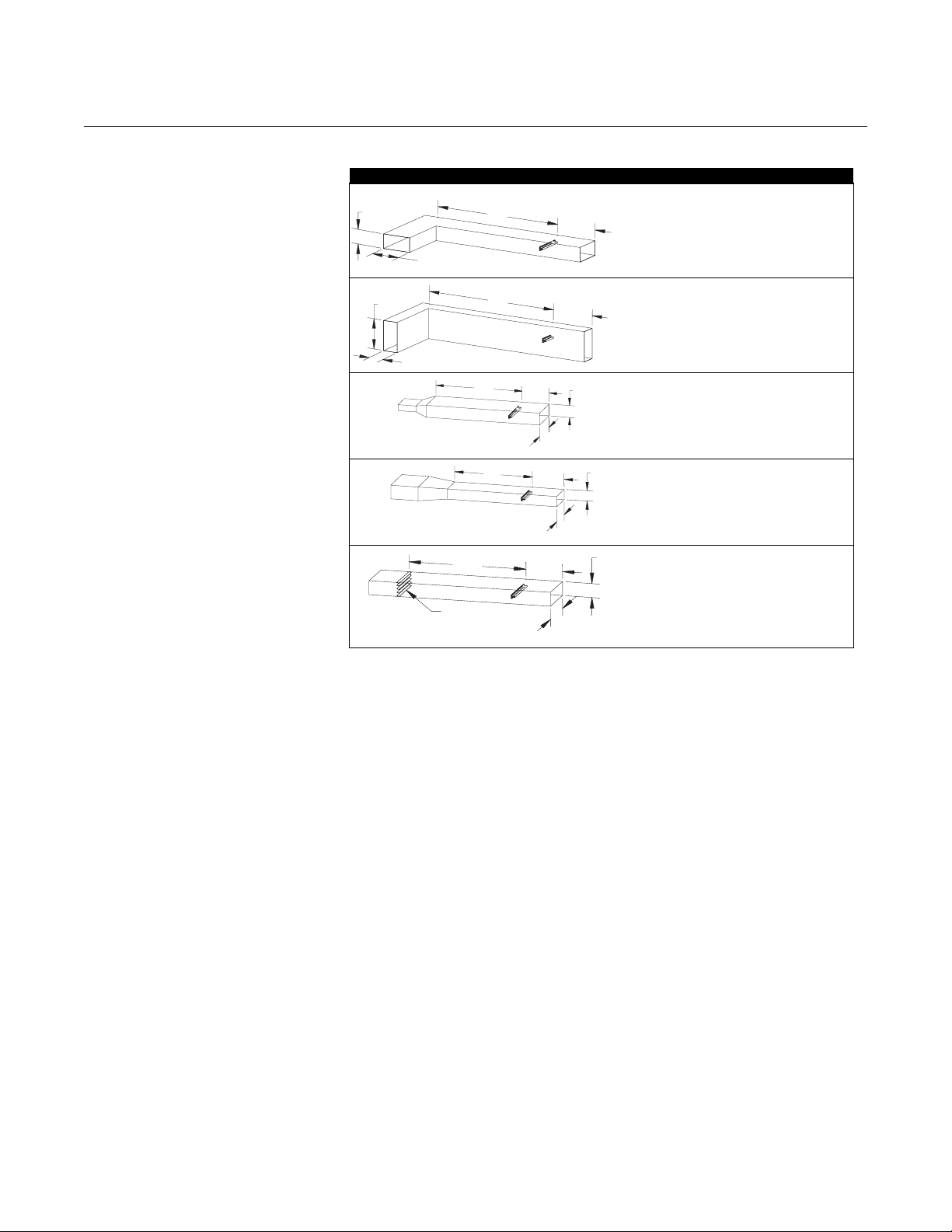
Reference Manual
1
1
00809-0100-4028, Rev AA
October 2005
Rosemount 285
Table 1. Minimum straight duct requirements for the 285 Annubar
Upstream Length Downstream Length
H
W
H
W
15W
7W
7W
2W
285/15-490028-901
2W
285/15-490029-901
H
2W
7W 2W
7W 2W
15W 2W
W
7W
2W
285/15-490030-90
H
7W 2W
15W
W
2W
285/15-490031-90
H
15W 2W
DAMPER
W
285/15-490032-901
A-5

Rosemount 285
Reference Manual
00809-0100-4028, Rev AA
October 2005
Flowmeter Orientation
Gas (Horizontal)
120
30
Liquid and Steam (Horizontal)
30°
120°
Gas (Vertical)
FLOW
360
30
15-490000-901
30°
15-490001-901
15-490002-901
A-6
Steam (Vertical)
360
Drill Hole Size According to Sensor Size
Sensor Size Diameter
1
2 15/16-in. (33 mm)
3
/4-in. (19 mm)
FLOW
15-490003-901

Reference Manual
00809-0100-4028, Rev AA
October 2005
OPTIONAL ROSEMOUNT 2024 TRANSMITTER SPECIFICATIONS
Rosemount 285
Performance Specifications
(Zero-based spans, reference conditions, and 316L SST isolating
diaphragms)
Accuracy
±0.25% of calibrated span. Includes combined effects of linearity, hysteresis,
and repeatability.
Dead Band
None
Stability
±0.25% of upper range limit for six months
Temperature Effect (Total)
Less than ±1.5% of upper range limit per 100 °F (55 °C)
Static Pressure Effect
Zero Error
• Less than ±0.5% of upper range limit per 1,000 psi (6.9 MPa). Correctable
through rezeroing at line pressure
Span Error
• Less than ±0.5% of reading per 1,000 psi (6.9 MPa)
Vibration Effect
Less than ±0.1% of upper range limit shift per test condition of SAMA PMC
31.1 Section 5.3
Functional Specifications
Power Supply Effect
Less than ±0.01% of calibrated span per volt
Load Effect
Output Code A
• No load effect other than the change in voltage supplied to the transmitter
Mounting Position Effect
Zero shift of up to 3.0 inH
Service
Liquid, gas, and vapor
Range
Code 2: 0–50 to 0–250 inH
Output
Code A: 4–20 mA dc, linear to DP
Power Supply
External power supply required
O (0.75 kPa), which can be calibrated
2
O (0–12.4 to 0–62.2 kPa)
2
A-7
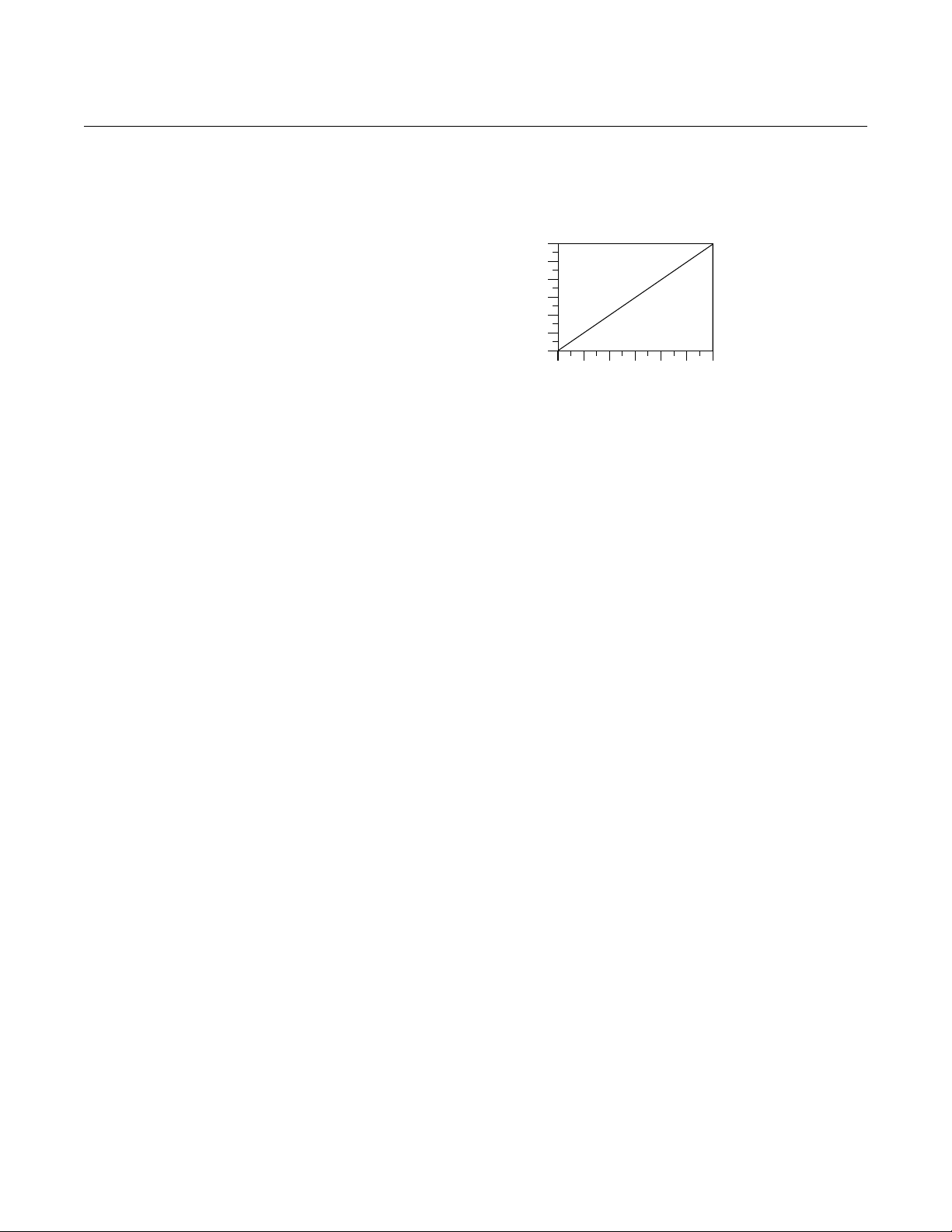
Rosemount 285
Reference Manual
00809-0100-4028, Rev AA
Output Code A: Operates on 12 to 36 V dc, with no load
Load Limitations
Output Code A
Maximum Load = 50 ⫻ (Power Supply Voltage – 12)
Span and Zero
Continuously adjustable
Temperature Limits
Process
• –20 to 220 °F (–29 to 104 °C)
Ambient
• –40 to 185 °F (–40 to 85 °C)
Storage
• –50 to 185 °F (–46 to 85 °C)
1200
1000
800
600
400
Load (Ohms)
200
0
12 16 20 24 28 32 36
Power Supply (V dc)
(1)
Operating
Region
October 2005
Static Pressure and Overpressure Limits
0 psia to 2,000 psig (0 to 13.79 MPa) on either side without damage to the
transmitter. Operates within specifications between static line pressures of
14.7 psia and 2,000 psig (0.1 to 13.79 MPa). 6,000 psig (41.37 MPa) burst
pressure
Humidity Limits
0 to 100% relative humidity
Damping
Fixed at a maximum of 0.2 second at reference conditions
Turn-on Tim e
Output Code A
• 1.5 seconds maximum at reference operating conditions
A-8
(1) Electronics temperature limits decrease three degrees for every one degree increase in pro-
cess temperature above 185 °F (85 °C).

Reference Manual
00809-0100-4028, Rev AA
October 2005
Optional 2024 Specifications Continued
Physical Specifications Process Connections
1
/4–18 NPT on 21/8-inch (54 mm) center
Electrical Connections
1
/2–14 NPT conduit connection, screw terminals, and internal grounding stud
Weight
6 lb. (2.7 kg) excluding options
Materials of Construction
Isolating Diaphragms
• 316L SST
Drain/Vent Valves
•316 SST
Flange
•316 SST
Wetted O-rings
• Glass filled TFE
Fill Fluid
• Silicone oil
Bolts
• Plated carbon steel
Electronics Housing
• Low-copper aluminum. NEMA 4X
Paint
• Polyurethane
Rosemount 285
Calibration Transmitters are factory calibrated to customer's specified range. If calibration
is not specified, transmitters are calibrated at maximum range. Calibration is
at ambient temperature and pressure.
OPTIONAL ROSEMOUNT 951 TRANSMITTER SPECIFICATIONS
Performance Specifications
Reference Accuracy
±0.25% of span for spans 1:1 to 6:1
±0.04% of URL for spans 6:1 to 40:1
Ambient Temperature Effect
±0.25% URL + 0.05% of Span per 50°F (28°C)
Mounting Effect
Zero shifts up to ± 0.01 inH
No span effect.
O which can be calibrated out.
2
A-9

Rosemount 285
s
Reference Manual
00809-0100-4028, Rev AA
October 2005
Time Response
Less than 200 milliseconds
Stability
0.125% of URL for 12 months
Power Supply Effect
Less than ±0.01% of calibrated span per volt
Functional Specifications
Figure A-1. Power Supply Load
Limitations, 4–20 mA
Transmitters
DP/GP Pressure Ranges
Range and Sensor Limits
Range Minimum Span
1 1.25 inH2O
(3.10 mbar)
Upper (URL) Lower (LRL)
25 inH2O
(62.3 mbar)
-25 inH2O
(-62.3 mbar)
Service
Non-condensing (0-95% relative humidity), non-combustible, non-corrosive,
and clean gases.
Output
2-wire 4-20 mA; linear or square root
®
HART
digital communication and configuration
Power Supply & Load Limits
External Power Supply required 10.5 to 36 V
Minimum 250 Ohms loop resistance for digital communications
Max. Loop Resistance = 43.5 ⫻ (Power Supply Voltage – 10.5)
1388
1109
1000
A-10
500
Load (Ohms)
0
10.5
Voltage (V dc)
Communication requires a minimum loop resistance of 250 ohm
Operating Region
20
30
36
40
951/0103C
Process and Ambient Temperature Limits
-40 to 185°F (-40 to 85°C)
Static and Overpressure Limit
100 psi (6,89 bar)

Reference Manual
00809-0100-4028, Rev AA
October 2005
Table A-3. Alarm Configuration
Rosemount 285
Burst Pressure
500 psi (34,47 bar)
Humidity Limits
0-95% relative humidity
Damping
Analog output response to a step input change is user-selectable from 0 to 60
seconds for one time constant. This software damping is in addition to sensor
module response time.
Failure Mode Alarm
If self-diagnostics detect a gross transmitter failure, the analog signal will be
driven offscale to alert the user.
High Alarm Low Alarm
Default - High Alarm ≥ 21.75 mA ≤ 3.75 mA
Turn-On Time
Performance within specifications less than 2.0 seconds after power is
applied to the transmitter
Physical Specifications Process Connections
1
/8 inch NPT stainless fittings to accommodate
any process connection
Process Connections include HDPE internal filter
Housing
NEMA 4X Delrin
IP 65
Anodized aluminum side mount bracket
Materials Exposed to Gases
•HAVAR
•Nitronic® 32
• Hastelloy C-276
• Ceramic
• Silicon Dioxide
Sensor Module Fill Fluid
None
®
Acetal
®
®
Shipping Weight
Approximately 1 lb. (0,45 kg.)
Electrical Connections
Terminal block with HART interface connections
A-11

Rosemount 285
DIMENSIONAL DRAWINGS
Reference Manual
00809-0100-4028, Rev AA
October 2005
Pak-Lok Rosemount 285 Annubar Primary
Front View Side View Top View
A
(1)
B
C
REMOTE MOUNT HEAD OPTION
(1) The Pak-Lok Annubar model is available up to 150# ANSI (275 psig at 100 °F (19 bar at 38 °C)).
TABLE 2. Rosemount 285 Annubar Primary - Pak-Lok
Sensor Size A (Max) B (Max) C (Max)
1 8.50 (215.9) 5.00 (127.0) 9.00 (228.6)
2 11.00 (279.4) 5.00 (127.0) 9.00 (228.6)
Dimensions are in inches (millimeters)
1
/4-in. NPT
Connection
A-12

Reference Manual
00809-0100-4028, Rev AA
October 2005
Front View Side View Top View
Rosemount 285
Dimensional Drawings (continued)
Duct Mount 285 Annubar Primary
A
TABLE 3. Rosemount 285 Annubar with Duct Mount
Sensor Size A (Max)
1 7.00 (177.8)
2 9.00 (228.6)
Dimensions are in inches (millimeters)
DIRECT MOUNT HEAD OPTION
WITH VALVES
285/15-49006-901,/15-49006-902, 15-49006-903
A-13

Rosemount 285
Duct Mount with Compression Fitting 285 Annubar Primary
Front View Side View Top View
Reference Manual
00809-0100-4028, Rev AA
October 2005
Dimensional Drawings (continued)
A
Note
Maximum opposite side stud length is 1
Sensor Size A (Max)
1 8.50 (215.9)
2 11.00 (279.4)
1
/2-in. (38 mm) long.
TABLE 4. Duct Mount with Compression Fitting
Dimensions are in inches (millimeters)
DIRECT MOUNT HEAD OPTION
WITH VALVES
A-14

Reference Manual
00809-0100-4028, Rev AA
October 2005
Rosemount 285
ORDERING INFORMATION
Rosemount 285 Annubar Primary Ordering Information
Model DP Flow Primary Type
285 Economy Annubar
Code Fluid Type
LLiquid
G Gas
S Steam
Code Line Size
020 2-in. (50 mm)
025 21/2-in. (63.5 mm)
030 3-in. (80 mm)
035 31/2-in. (89 mm)
040 4-in. (100 mm)
050 5-in. (125 mm)
060 6-in. (150 mm)
080 8-in. (200 mm)
100 10-in. (250 mm)
120 12-in. (300 mm)
140 14-in. (350 mm)
160 16-in. (400 mm)
180 18-in. (450 mm)
200 20-in. (500 mm)
240 24-in. (600 mm)
300 30-in. (750 mm)
360 36-in. (900 mm)
420 42-in. (1066 mm)
480 48-in. (1210 mm)
600 60-in. (1520 mm)
720 72-in. (1820 mm)
Code Pipe I.D. Range (Refer to Pipe ID Range Table for Code)
A Range A from the Pipe I.D. table
B Range B from the Pipe I.D. table
C Range C from the Pipe I.D. table
D Range D from the Pipe I.D. table
E Range E from the Pipe I.D. table
Z Non-standard Pipe I.D. Range or Line Sizes greater than 12 inches (sensor size 2) or greater than 8 inches (sensor size 1).
Code Piping Configuration
CCircular
R Rectangular or Square
Code Pipe Material/Mounting Assembly Material
C Carbon Steel
S 316 Stainless Steel
0 No Mounting (Customer Supplied)
Code Annubar Typ e
P1 Pak-Lok
D1 Duct Mount Plate without Compression Fitting
D2 Duct Mount Plate with Compression Fitting
Continued on Next Page
A-15

Reference Manual
00809-0100-4028, Rev AA
Rosemount 285
Code Sensor Material
S 316 Stainless Steel
Code Sensor Size
1 Sensor Size 1
2 Sensor Size 2
Code Electronics Connection Platform
3 Direct-mount
7 Remote-mount NPT Connections
Code Options
Instrument Connections for Remote Mount Option
G1 Needle Valves, CS
G2 Needle Valves, SS
B1 Ball Valves, CS
B2 Ball Valves, SS
Variable Mount Height
VM Variable Mounting Height for Customer Supplied Mounting
(1)
X01
(2)
X12
(2)
X22
(2)
X32
(3)
F2
QC1 Visual and Dimensional Inspection w/Cert
QC7 Inspection and Performance Certificate
Q8 Material Cert per ISO 10474 3.1.B and EN 10204 3.1.B
Y1 Mounting Hardware Shipped Separately
(1) Available with electronics connection platform code '7' and fluid type 'G' only. Transmitter is supplied with mounting bracket.
(2) Minimum span is 50-in. (1270 mm)
(3) Applies to 285 Primary Element only
(3) If F2 option is ordered with Electronic Connections Platform Code '3' (Direct Mount), manifold is integral to head. If F2 is ordered with Code '7' (Remote
Mount), the manifold is supplied loose.
Transmitter
951 Dry Gas Pressure Transmitter
2024D Range 2 D.P. Transmitter (4-20 mA output)
2024D Range 2 D.P. Transmitter (4-20 mA output) with CSA E.P. / I.S.
2024D Range 2 D.P. Transmitter (4-20 mA output) with FM E.P. / I.S.
Manifold
3-Valve Manifold, SST
Special Inspection
Material Traceability Certification
(3)
(3)
Special Shipment
October 2005
A-16

Reference Manual
00809-0100-4028, Rev AA
October 2005
Rosemount 285
Pipe I.D. Range Code–
measured in inches
(millimeters)
Line Size
Nominal
2-in.
(50 mm)
2
(63.5 mm)
3-in.
(80 mm)
3
(89 mm)
4-in.
Size 1
(100 mm)
Sensor
5-in.
(125 mm)
6-in.
(150 mm)
8-in.
(200 mm)
8-in.
(200 mm)
10-in.
(250 mm)
Size 2
Sensor
12-in.
(300 mm)
1
/2-in.
1
/2-in.
Max.
O.D.
2.625-in.
(66.68 mm)
3.188-in.
(80.98 mm)
3.75-in.
(95.25 mm)
4.25-in.
(107.95 mm)
5.032-in.
(127.81 mm)
6.094-in.
(154.79 mm)
6.93-in.
(176.02 mm)
9.688-in.
(246.08 mm)
9.688-in.
(246.08 mm)
11.75-in.
(298.45 mm)
13.0375-in.
(331.15 mm)
Option
Code
020
025
030
035
040
050
060
080
080
100
120
See “Rosemount 285 Annubar Primary Ordering Information” on page A-15
For pipes with an Inner Diameter (I.D.) Range / Pipe Wall Thickness not found
in this table or with a line size greater than 12-in. (300 mm), choose option
code Z and specify the exact pipe dimensions (I.D. and Pipe Wall Thickness)
on the Configuration Data Sheet (00813-0100-4028). The Emerson process
Management sizing program will determine this code, based on the
application piping.
Pipe Wall Thickness
Inner Diameter (I.D.) Range
1.784 to 1.841-in. (45.31 to 46.76 mm) 0.065 to 0.545-in.
1.842 to 1.938-in. (46.79 to 49.23 mm) 0.065 to 0.449-in. (1.7 to 11.4 mm) B
1.939 to 2.067-in. (49.25 to 52.50 mm) 0.065 to 0.417-in. (1.7 to 10.6 mm) C
2.068 to 2.206-in. (52.53 to 56.03 mm) 0.065 to 0.407-in. (1.7 to 10.3 mm) D
2.207 to 2.322-in. (56.06 to 58.98 mm) 0.083 to 0.563-in.
2.323 to 2.469-in. (59.00 to 62.71 mm) 0.083 to 0.417-in. (2.1 to 10.6 mm) C
2.470 to 2.598-in. (62.74 to 65.99 mm) 0.083 to 0.435-in. (2.1 to 11.0 mm) D
2.599 to 2.647-in. (66.01 to 67.23 mm) 0.083 to 0.515-in. (2.1 to 13.1 mm) E
2.648 to 2.751-in. (67.26 to 69.88 mm) 0.083 to 0.563-in.
2.752 to 2.899-in. (69.90 to 73.63 mm) 0.083 to 0.416-in. (2.1 to 10.6 mm) B
2.900 to 3.068-in. (73.66 to 77.93 mm) 0.083 to 0.395-in. (2.1 to 10.0 mm) C
3.069 to 3.228-in. (77.95 to 81.99 mm) 0.083 to 0.404-in (2.1 to 10.3 mm) D
3.229 to 3.333-in. (82.02 to 84.66 mm) 0.120 to 0.600-in.
3.334 to 3.548-in. (84.68 to 90.12 mm) 0.120 to 0.386-in. (3.0 to 9.8 mm) C
3.549 to 3.734-in. (90.14 to 94.84 mm) 0.120 to 0.415-in. (3.0 to 10.5 mm) D
3.735 to 3.825-in. (94.87 to 97.16 mm) 0.120 to 0.600-in.
3.826 to 4.026-in. (97.18 to 102.26 mm) 0.120 to 0.400-in. (3.0 to 10.2 mm) C
4.027 to 4.237-in. (102.29 to 107.62 mm) 0.120 to 0.390-in. (3.0 to 9.9 mm) D
4.238 to 4.437-in. (107.65 to 112.70 mm) 0.120 to 0.401-in. (3.0 to 10.2 mm) E
4.438 to 4.571-in. (112.73 to 116.10 mm) 0.134 to 0.614-in.
4.572 to 4.812-in. (116.13 to 122.22 mm) 0.134 to 0.374-in. (3.4 to 9.5 mm) B
4.813 to 5.047-in. (122.25 to 128.19 mm) 0.134 to 0.380-in. (3.4 to 9.7 mm) C
5.048 to 5.249-in. (128.22 to 133.32 mm) 0.134 to 0.413-in. (3.4 to 10.5 mm) D
5.250 to 5.472-in. (133.35 to 138.99 mm) 0.134 to 0.614-in.
5.473 to 5.760-in. (139.01 to 146.30 mm) 0.134 to 0.327-in. (3.4 to 8.3 mm) B
5.761 to 6.065-in. (146.33 to 154.05 mm) 0.134 to 0.310-in. (3.4 to 7.9 mm) C
6.066 to 6.383-in. (154.08 to 162.13 mm) 0.134 to 0.297-in. (3.4 to 7.5 mm) D
7.393 to 7.624-in. (187.78 to 193.65 mm) 0.250 to 0.73-in.
7.625 to 7.981-in. (193.68 to 202.72 mm) 0.250 to 0.374-in. (6.4 to 9.5 mm) C
7.982 to 8.400-in. (202.74 to 213.36 mm) 0.250 to 0.312-in. (6.4 to 7.9 mm) D
8.401 to 8.766-in. (213.39 to 222.66 mm) 0.250 to 0.364-in. (6.4 to 9.2 mm) E
7.393 to 7.624-in. (187.78 to 193.65 mm) 0.250 to 1.47-in.
7.625 to 7.981-in. (193.68 to 202.72 mm) 0.250 to 1.114-in. (6.4 to 28.3 mm) C
7.982 to 8.400-in. (202.74 to 213.36 mm) 0.250 to 1.052-in. (6.4 to 26.7 mm) D
8.401 to 8.766-in. (213.39 to 222.66 mm) 0.250 to 1.104-in. (6.4 to 28.0 mm) E
8.767 to 9.172-in. (222.68 to 232.97 mm) 0.250 to 1.470-in.
9.173 to 9.561-in. (232.99 to 242.85 mm) 0.250 to 1.082-in. (6.4 to 27.5 mm) B
9.562 to 10.020-in. (242.87 to 254.51 mm) 0.250 to 1.012-in. (6.4 to 25.7 mm) C
10.021 to 10.546-in. (254.53 to 267.87 mm) 0.250 to 0.945-in. (6.4 to 24.0 mm) D
10.547 to 10.999-in. (267.89 to 279.37 mm) 0.250 to 1.018-in. (6.4 to 25.9 mm) E
11.000 to 11.373-in. (279.40 to 288.87 mm) 0.250 to 1.470-in.
11.374 to 11.938-in. (288.90 to 303.23 mm) 0.250 to 0.906-in. (6.4 to 23.0 mm) C
11.939 to 12.250-in. (303.25 to 311.15 mm) 0.250 to 1.159-in. (6.4 to 29.4 mm) D
ANSI Pipes Non-ANSI Pipes
(1.7 to 13.8 mm)
(2.1 to 14.3 mm)
(2.1 to 14.3 mm)
(3.0 to 15.2 mm)
(3.0 to 15.2 mm)
(3.4 to 15.6 mm)
(3.4 to 15.6 mm)
(6.4 to 18.5 mm)
(6.4 to 37.3 mm)
(6.4 to 37.3 mm)
(6.4 to 37.3 mm)
0.065 to 0.488-in. (1.7 to 12.4 mm) A
0.083 to 0.448-in. (2.1 to 11.4 mm) B
0.083 to 0.460-in. (2.1 to 11.7 mm) A
0.120 to 0.496-in. (3.0 to 12.6 mm) B
0.120 to 0.510-in. (3.0 to 13.0 mm) B
0.134 to 0.481-in. (3.4 to 12.2 mm) A
0.134 to 0.392-in. (3.4 to 9.9 mm) A
0.250 to 0.499-in. (6.4 to 12.6 mm) B
0.250 to 1.239-in. (6.4 to 31.4 mm) B
0.250 to 1.065-in. (6.4 to 27.1 mm) A
0.250 to 1.097-in. (6.4 to 27.9 mm) B
I.D.
Range
Code
A-17

Rosemount 285
Reference Manual
00809-0100-4028, Rev AA
October 2005
A-18

Reference Manual
00809-0100-4028, Rev AA
October 2005
Appendix B Approvals
Hazardous Locations Installations . . . . . . . . . . . . . . . . . . page B-1
Rosemount 2024 Product Certifications . . . . . . . . . . . . . page B-1
Rosemount 285
HAZARDOUS LOCATIONS INSTALLATIONS
ROSEMOUNT 2024 PRODUCT CERTIFICATIONS
Approved Manufacturing Locations
European Directive Information
The flowmeter is designed with explosion-proof housings and circuitry
suitable for intrinsically safe and non-incendive operation. Each flowmeter is
clearly marked with a tag indicating the approvals. To maintain certified
ratings for installed transmitters, install in accordance with all applicable
installation codes and approval drawings. Verify that the operating
atmosphere of the transmitter is consistent with the appropriate hazardous
locations certifications. Both transmitter covers must be fully engaged to meet
explosion proof requirements.
Rosemount Inc. — Chanhassen, Minnesota USA
Fisher-Rosemount GmbH & Co. — Wessling, Germany
Emerson Process Management Asia Pacific
Private Limited — Singapore
Beijing Rosemount Far East Instrument Co., LTD — Beijing, China
The EC declaration of conformity for all applicable European directives for this
product can be found on the Rosemount website at www.rosemount.com. A
hard copy may be obtained by contacting our local sales office.
ATEX Directive (94/9/EC)
Emerson Process Management complies with the ATEX Directive.
www.rosemount.com
Ordinary Location Certification for Factory Mutual
As standard, the transmitter has been examined and tested to determine that
the design meets basic electrical, mechanical, and fire protection
requirements by FM, a nationally recognized testing laboratory (NRTL) as
accredited by the Federal Occupational Safety and Health Administration
(OSHA).

Rosemount 285
Reference Manual
00809-0100-4028, Rev AA
October 2005
Hazardous Locations Certifications
North American Certifications
Factory Mutual (FM) Approvals
E5 Explosion Proof for Class I, Division 1, Groups B, C, and D; Dust-Ignition
Proof for Class II, Division 1, Groups E, F, and G. Suitable for Class III,
Division 1, indoor and outdoor (NEMA 4X) hazardous locations.
I5 Intrinsically safe for use in Class I, Division 1, Groups A, B, C, and D;
Class II Division 1, Groups E, F, and G; and Class III, Division 1 when
connected in accordance with Rosemount drawing 02024-0150. Temp.
Code T4. Non-incendive for Class I, Division 2, Groups A, B, C, and D.
K5 Combined E5 and I5. Standard Offering
Canadian Standards Association (CSA) Approvals
C6 Explosion Proof for Class I, Division 1, Groups C and D; Dust-ignition
Proof for Class II, Division 1, Groups E, F, and G; Suitable for Class III,
indoor and outdoor hazardous locations, CSA enclosure 4x. Approved
for Class I, Division 2, Groups A, B, C, and D.
Intrinsically safe for Class I, Division I, Groups A, B, C, and D when
connected in accordance with Rosemount drawing 02024-1064. Temp.
Code T3C.
B-2


Annubar Flowmeter Series
Reference Manual
00809-0100-4809, Rev AA
May 2002
Rosemount, the Rosemount logotype, Annubar, and ProBar are registered trademarks of Rosemount Inc.
HART is a registered trademark of the HART Communication Foundation.
OUNDATION is a trademark of the Fieldbus Foundation.
F
Loctite and PST are registered trademarks of the Loctite Corporation.
Hastelloy is a registered trademark of Haynes International.
Teflon (PTFE) is a registered trademark of E.I du Pont de Nemours & Co.
All other marks are the property of their respective owners.
Emerson Process Management
Rosemount Inc.
8200 Market Boulevard
Chanhassen, MN 55317 USA
T (U.S.) 1-800-999-9307
T (International) (952) 906-8888
F (952) 949-7001
www.rosemount.com
¢00809-0100-4809g¤
© 2005 Rosemount Inc. All rights reserved.
 Loading...