

Page 1

Reference Manual
303032EN, Edition 3
May 2013
Rosemount TankMaster
Redundancy System
Switch
Switch
Primary Backup
Replication
of data
r
a
d
Ra
k
n
a
T
t
oun
r
m
a
e
d
s
o
Ra
R
k
n
a
T
t
n
u
o
em
os
R
Rx
Tx
USB
AI
G
RS-232
o
Ext. pwr
L
2180
M
B
F
ff
O
-
M
ER
T
n
Rx
O
Tx
i
H
N
USB
ff
AI
O
G
RS-232
-
-
M
o
Ext. pwr
L
ER
T
n
O
i
H
N
2180
M
B
F
r
a
d
Ra
k
n
a
T
t
n
ou
em
s
o
R
f
f
O
-
M
ER
T
n
Rx
O
Tx
i
H
N
USB
AI
G
RS-232
o
Ext. pwr
L
2180
M
B
F
r
a
d
Ra
k
n
a
T
t
n
u
o
m
e
s
o
R
f
f
O
-
M
ER
T
n
Rx
O
Tx
i
H
N
USB
AI
G
RS-232
o
Ext. pwr
L
0
218
M
B
F
www.rosemount-tg.com
Page 2

Page 3

Reference Manual
303032EN, Edition 3
May 2013
Rosemount TankMaster Redundancy
Table of Contents
SECTION 1
Getting Started
SECTION 2
System Overview
SECTION 3
Installation
1.1 What is TankMaster Redundancy? . . . . . . . . . . . . . . . . . . . . . . 1-1
1.2 TankMaster Software Package . . . . . . . . . . . . . . . . . . . . . . . . . 1-2
1.3 Installing the TankMaster Software . . . . . . . . . . . . . . . . . . . . . . 1-4
1.3.1 Software . . . . . . . . . . . . . . . . . . . . . . . . . . . . . . . . . . . 1-4
1.3.2 Hardware . . . . . . . . . . . . . . . . . . . . . . . . . . . . . . . . . . 1-4
1.3.3 Installation Procedure. . . . . . . . . . . . . . . . . . . . . . . . . 1-5
1.4 Server Hardware Key . . . . . . . . . . . . . . . . . . . . . . . . . . . . . . . 1-10
1.4.1 System Type . . . . . . . . . . . . . . . . . . . . . . . . . . . . . . 1-10
1.4.2 Supported Functions . . . . . . . . . . . . . . . . . . . . . . . . 1-11
1.4.3 Tanks . . . . . . . . . . . . . . . . . . . . . . . . . . . . . . . . . . . . 1-11
1.4.4 TM Network Client Nodes . . . . . . . . . . . . . . . . . . . . 1-11
1.4.5 Illegal characters . . . . . . . . . . . . . . . . . . . . . . . . . . . 1-12
2.1 Normal Operation . . . . . . . . . . . . . . . . . . . . . . . . . . . . . . . . . . . 2-3
2.2 Backup Operation . . . . . . . . . . . . . . . . . . . . . . . . . . . . . . . . . . . 2-4
2.3 Service Operation . . . . . . . . . . . . . . . . . . . . . . . . . . . . . . . . . . . 2-6
3.1 Windows Configuration . . . . . . . . . . . . . . . . . . . . . . . . . . . . . . . 3-3
3.1.1 Windows network configuration . . . . . . . . . . . . . . . . . 3-3
3.1.2 Configure regional and language settings . . . . . . . . . 3-5
3.1.3 Redundant network cards . . . . . . . . . . . . . . . . . . . . . 3-6
3.1.4 TankMaster installation . . . . . . . . . . . . . . . . . . . . . . 3-10
3.1.5 Configuring the Windows Firewall . . . . . . . . . . . . . . 3-10
3.1.6 Access permission on shared folder TM . . . . . . . . . 3-13
3.2 Time Server Installation. . . . . . . . . . . . . . . . . . . . . . . . . . . . . . 3-15
3.3 Client and WinOpi Installation . . . . . . . . . . . . . . . . . . . . . . . . . 3-18
3.3.1 Configure Time Synchronization Client . . . . . . . . . . 3-18
3.3.2 Configure WinOpi Client. . . . . . . . . . . . . . . . . . . . . . 3-19
3.4 Redundant Network configuration . . . . . . . . . . . . . . . . . . . . . . 3-20
3.4.1 Switch. . . . . . . . . . . . . . . . . . . . . . . . . . . . . . . . . . . . 3-21
SECTION 4
Operation
www.rosemount-tg.com
4.1 Administrator program . . . . . . . . . . . . . . . . . . . . . . . . . . . . . . . . 4-1
4.1.1 TankMaster Redundancy . . . . . . . . . . . . . . . . . . . . . . 4-2
4.1.2 The control buttons. . . . . . . . . . . . . . . . . . . . . . . . . . . 4-2
4.1.3 Redundancy window . . . . . . . . . . . . . . . . . . . . . . . . . 4-3
4.2 WinOpi. . . . . . . . . . . . . . . . . . . . . . . . . . . . . . . . . . . . . . . . . . . . 4-4
4.2.1 Redundancy . . . . . . . . . . . . . . . . . . . . . . . . . . . . . . . . 4-4
4.2.2 Messages and alerts . . . . . . . . . . . . . . . . . . . . . . . . . 4-4
4.3 General failures . . . . . . . . . . . . . . . . . . . . . . . . . . . . . . . . . . . . . 4-5
4.4 Server case scenarios . . . . . . . . . . . . . . . . . . . . . . . . . . . . . . . . 4-6
4.4.1 Primary Server failed resulting in a Failover. . . . . . . . 4-6
4.4.2 Backup Server has failed but Primary Server is
still running . . . . . . . . . . . . . . . . . . . . . . . . . . . . . . . . . 4-6
Page 4

Rosemount TankMaster Redundancy
4.4.3 Server failure resulting in two Primary Servers . . . . . 4-6
4.4.4 Database synchronization problems . . . . . . . . . . . . . 4-7
4.5 Service. . . . . . . . . . . . . . . . . . . . . . . . . . . . . . . . . . . . . . . . . . . . 4-7
4.6 Server status . . . . . . . . . . . . . . . . . . . . . . . . . . . . . . . . . . . . . . . 4-8
Reference Manual
303032EN, Edition 3
May 2013
SECTION 5
Redundancy checklist
SECTION 6
Trouble Shooting
5.1 Verify TankMaster Redundancy . . . . . . . . . . . . . . . . . . . . . . . . 5-1
5.2 Verify Network Redundancy . . . . . . . . . . . . . . . . . . . . . . . . . . . 5-1
6.1 DCOM error messages . . . . . . . . . . . . . . . . . . . . . . . . . . . . . . . 6-1
6.1.1 Server not available . . . . . . . . . . . . . . . . . . . . . . . . . . 6-1
6.1.2 Access is denied . . . . . . . . . . . . . . . . . . . . . . . . . . . . 6-1
6.1.3 Server execution failed. . . . . . . . . . . . . . . . . . . . . . . . 6-1
6.1.4 System message about protocol servers ... . . . . . . . . 6-1
6.1.5 The object exporter specified was not found . . . . . . . 6-1
6.1.6 The object is disconnected from its clients. . . . . . . . . 6-2
6.2 Check Configuration of DCOM settings. . . . . . . . . . . . . . . . . . . 6-2
6.3 WinOpi failures . . . . . . . . . . . . . . . . . . . . . . . . . . . . . . . . . . . . . 6-6
6.3.1 No tanks are displayed. . . . . . . . . . . . . . . . . . . . . . . . 6-6
6.3.2 Redundancy restored but error message still present 6-6
6.4 Other . . . . . . . . . . . . . . . . . . . . . . . . . . . . . . . . . . . . . . . . . . . . . 6-7
6.4.1 Unable to connect to shared folder TM . . . . . . . . . . . 6-7
6.4.2 Database copying problem. . . . . . . . . . . . . . . . . . . . . 6-7
6.4.3 Firewall setup . . . . . . . . . . . . . . . . . . . . . . . . . . . . . . . 6-7
6.4.4 Redundancy configuration not correct . . . . . . . . . . . . 6-7
TOC-2
Table of Contents
Page 5

Reference Manual
303032EN, Edition 3
May 2013
Rosemount TankMaster Redundancy
Section 1 Getting Started
1.1 What is TankMaster Redundancy? . . . . . . . . . . . . .page 1-1
1.2 TankMaster Software Package . . . . . . . . . . . . . . . . page 1-2
1.3 Installing the TankMaster Software . . . . . . . . . . . . . page 1-4
1.4 Server Hardware Key . . . . . . . . . . . . . . . . . . . . . . . . page 1-10
1.1 WHAT IS TANKMASTER REDUNDANCY?
A measurement system that requires high availability is preferably designed
as a redundant system. This means that vital parts of the system exist in pairs
to store the same data continuously. If either part is out of service or needs
maintenance, the other part can take over without losing work effectivity or
important data.
TankMaster is an Emerson Process Management/Rosemount Tank
Gauging inventory management software package for installation and
configuration of level gauging equipment. Redundancy is an add-on
application that applies on the Tank Server. Redundancy can also be
performed at the Field Communication Unit (FCU) level, see Rosemount
TankRadar REX Service Manual.
TankMaster provides you with powerful and easy-to-use tools for installation
and configuration of level gauging devices such as radar transmitter gauges
(RTGs). The settings for protocols, devices and tanks can be changed in real
time.
The graphical interface gives you a clear overview of installed devices and
tanks. For each tank you can easily see the associated transmitters in the
WinSetup application.
Key Features
• Monitoring of measured data
• Clear overview of installed tanks and devices (using WinSetup)
• Simple installation using wizards (using WinSetup)
• Open connectivity
• Object-oriented, user-friendly Graphical User Interface (GUI)
www.rosemount-tg.com
®
TankMaster is designed to be used in a Microsoft
providing easy access to measurement data from any PC in your network.
Measurements and data are presented in realtime and you can customize
views to suit your needs.
TankMaster supports the communication protocols Modbus, Enraf GPU, and
OPC DA. As TankMaster is based on the open OPC standard, this allows you
to import data into other systems, such as DCSs, PLCs, Scada systems and
Microsoft Office programs.
Windows environment,
Page 6

Rosemount TankMaster Redundancy
Reference Manual
303032EN, Edition 3
May 2013
1.2 TANKMASTER SOFTWARE PACKAGE
The TankMaster software package comprises the following software
modules:
• WinOpi or WinView
• WinSetup
• Tank Server
• Master Protocol server
• Slave Protocol Server
WinOpi/WinSetup
Tank Server
Master Protocol Server Slave Protocol Server
COM1 COM2
WinOpi
WinOpi is the complete operator interface to the tank gauging system. It
communicates with the Tank Server and various protocol servers to let the
user monitor measured tank data. WinOpi also provides:
• alarm handling
• automatic report distribution
• historical data sampling
• inventory calculations for volume, density, mass and other parameters.
WinView
WinView is the operator interface with basic inventory capabilities for the tank
gauging system. It communicates with the Tank Server and the different
protocol servers to let the user monitor measured tank data. WinView also
provides alarm handling, and automatic report handling.
WinSetup
The WinSetup program is a graphical user interface (GUI) for installation,
configuration and maintenance of level gauging devices.
1-2
Section 1. Getting Started
Page 7

Reference Manual
303032EN, Edition 3
May 2013
Rosemount TankMaster Redundancy
Tank Server
The Tank Server communicates with devices via the Master Protocol Server
and handles configuration data for all installed tanks and devices. Parameters
stored by the Tank Server include, for example:
• device names
• configuration data, such as tank type, antenna type, etc
• number of connected temperature sensors
• number of connected analog inputs
The Tank Server collects data from connected devices and distributes this
information to the WinOpi and WinSetup user interfaces.
Master Protocol Server
The Master Protocol Server transfers configuration data and measured data
between the Tank Server and connected devices in the tank gauging system.
The Master Protocol Server is able to communicate with various types of
devices such as FCUs, the Rosemount 2410 Tank Hub, and the Rosemount
5900S Radar Level Gauge to collect measurements for, for example, level,
temperature and pressure.
Slave Protocol
The Slave Protocol Server is used to connect the TankMaster system to a
host computer (DCS system). The Slave Protocol Server exchanges tank
data between the Tank Server and the host computer via serial link, Modbus
RTU.
OPC Server with Browser
TankMaster uses OPC Data Access 2.0 (OLE for Process Control), an open
industry standard, which eliminates the need for costly customized software
integration.
With the OPC server and the browser it is easy to import all custody transfer
and inventory data to other OPC clients such as different DCS:s, PLC:s,
Scada systems, or Microsoft Office® programs.
See the web site for the OPC Foundation for more information:
www.opcfoundation.org
Customized Views
You can customize specific views and windows in TankMaster. Existing
objects can be modified, or new ones created. You could, for example, create
a window with an embedded image of your own plant to give a realistic
overview, and configure the window so that when you click on a specific tank
in the image, you can access the corresponding data for that tank.
Section 1. Getting Started
1-3
Page 8

Rosemount TankMaster Redundancy
Reference Manual
303032EN, Edition 3
May 2013
1.3 INSTALLING THE TANKMASTER SOFTWARE
1.3.1 Software
1.3.2 Hardware
The following minimum system requirements must be met in order to run
TankMaster version 6.B2 or higher
Operating System Language
Windows 7 Professional (32 and 64 bit) SP1
Windows 2008 Server Standard
(32 and 64 bit) SP2
Windows Server 2008 R2 SP1
Component Requirement
PC DELL recommended.
Processor
Hard Disk 40 GB of available space.
(1)
:
English
• 2.5 GHz (multi core processor) for
Windows 7 and Windows Server 2008
• TankMaster + SQL Server 2005 Express
needs approximately 600 MB
• Windows 7 and Windows Server 2008
needs at least 15 GB of available space
RAM For Windows 7: 4 GB
For Windows 2008 Server Std /
/ Server 2008 R2: 4 GB
Serial Ports Two RS-232 serial ports are required, one
serial for each protocol channel.
(USB can be used if no RS-232 exists)
USB One USB port for each TankMaster hardware
key.
Monitor 22 inch or larger recommended.
Graphics Card 1152*864, 65536 colors.
Hardware Key One key for each TankMaster server PC.
Connected TankMaster view nodes do not
require a hardware key.
Field Bus Modem: (USB) Part no. 9240002-635
1-4
(1) For previous TankMaster versions other system requirements apply. Please contact
Emerson Process Management/Rosemount Tank Gauging for more information.
Section 1. Getting Started
Page 9

Reference Manual
303032EN, Edition 3
May 2013
Rosemount TankMaster Redundancy
1.3.3 Installation Procedure
To install the TankMaster software package:
1. Insert the TankMaster CD-ROM.
NOTE!
If the installation wizard does not start automatically when the CD-ROM is
inserted, double-click the file TMSetup.exe on the TankMaster CD-ROM.
2. To Install Acrobat Reader in order to read the TankMaster manuals in
pdf format, click the Acrobat Reader button and follow the on-screen
instructions.
3. To open the TankMaster WinOpi or WinSetup reference manuals, click
the Manuals button, select a manual and click the View button.
4. To proceed with the TankMaster installation click the Install button on
the splash screen, and follow the on-screen instructions of the wizard
until the installation is finished.
Section 1. Getting Started
1-5
Page 10

Rosemount TankMaster Redundancy
5. The installation CD contains a number of installation options:
Demo TankMaster in demo mode with demo database.
Client Client installation only will be installed.
Server and Client Suitable for standalone systems, and for network servers.
Redundant server Server installation including redundant Tank Server setup.
Choose Redundant Server Installation on the Setup Type screen to
configure a server in a redundancy system. Clear the check box Install
Batch Server, if a Batch server is not needed in the system.
Reference Manual
303032EN, Edition 3
May 2013
Suitable for network clients connected to a common Tank Server,
or in systems with redundant servers.
1-6
6. Remember to check the box on the TankServer Redundancy
Configuration screen, if the current server is intended to be the Primary
server for the system redundancy.
Browse the network to choose the Backup server and get the exact
computer name entered in the Buddy server field.
Section 1. Getting Started
Page 11

Reference Manual
303032EN, Edition 3
May 2013
Enter Primary server
Rosemount TankMaster Redundancy
7. When installing the Redundancy program in the Backup server, leave
the box unchecked, but remember to browse the network, or manually
enter the exact name of the Primary server in the Buddy server field.
8. To configure a Client, select Client Installation on the Setup Type
screen.
Section 1. Getting Started
1-7
Page 12
Rosemount TankMaster Redundancy
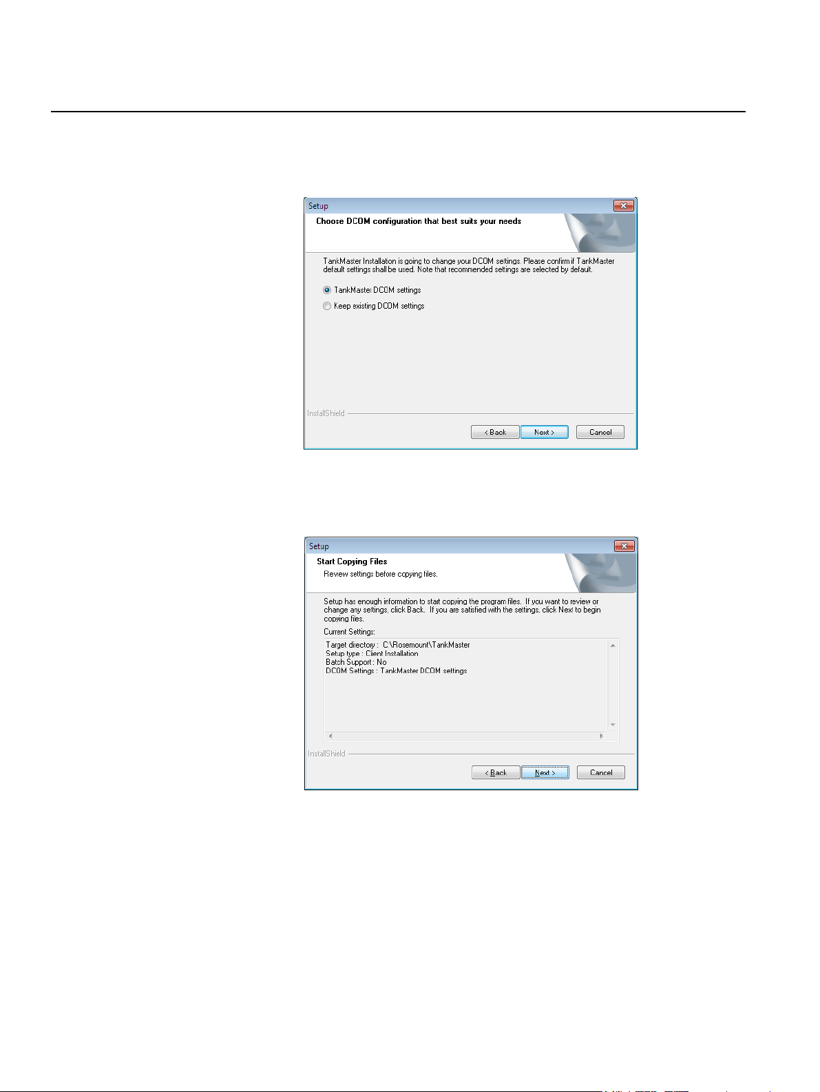
9. The InstallationShield Wizard will suggest necessary changes in the PC
Setup. If, for example, the DCOM settings need changes, the following
screen pops up:
Reference Manual
303032EN, Edition 3
May 2013
10. Check the current program settings before start copying the program
files.
1-8
Section 1. Getting Started
Page 13

Reference Manual
303032EN, Edition 3
May 2013
Rosemount TankMaster Redundancy
11. When the InstallShield Wizard Complete screen turns up, restart the
computer to start the TankMaster program.
Ini Files
Tankmaster ini-files are required to read holding and input register data from
field devices. These devices are available in WinSetup once installed.
If WinSetup indicates that the ini-files were not successfully installed, and they
need to be re-installed, or updated, they can be installed separately without
reinstalling TankMaster.
Simply repeat step.1 of the Installation Procedure and click the Inifiles button.
Section 1. Getting Started
1-9
Page 14

Rosemount TankMaster Redundancy
Reference Manual
303032EN, Edition 3
May 2013
1.4 SERVER HARDWARE KEY
The Server Hardware Key Info window displays the functions enabled by the
TankMaster hardware key. The information displayed is only valid for the
selected server and cannot be altered. Also shown is the number of tanks that
can be installed according to the TankMaster license, and the current number
of installed tanks.
To access the Server Hardware Key Info window:
1. Go to the Tools menu and select View Server HW Key Info.
2. Select a server.
3. To close the Server Hardware Key Info window, click Close.
1.4.1 System Type The System Type indicates in which mode TankMaster is running.
Inventory System
TankMaster runs as a complete custody transfer and inventory software
package. All calculations are based on current API and ISO standards.
WinView System
WinView basic inventory capabilities suitable for smaller plants and terminals.
Demo System
TankMaster is running with full functionality and all values are simulated
without any communication to the field devices.
1-10
Section 1. Getting Started
Page 15

Reference Manual
303032EN, Edition 3
May 2013
Rosemount TankMaster Redundancy
1.4.2 Supported Functions
The Supported Functions pane in the Server Hardware Key Info window
shows available TankMaster options. Selected options indicate that the
corresponding function is enabled with the current hardware key. The table
below gives an overview of the available functions:
Function Explanation
Host Access to server via OPC and
serial
Redundancy Enables the use of redundant servers
Network access for TM client nodes Enables a TankMaster client to connect to the network
Extended Batch Function
Custody Transfer System Setup mode for the Custody Transfer System.
Custody Transfer Seal Write-protected mode. No possibility to change
HTG calculation and Setup Hydrostatic Tank Gauging, Enables level and inventory
Window Customizing Enables the creation of customized windows.
(a)
Enables OPC and Modbus communications between
TankMaster and SCADA/DCS
and read tank and device data.
Creates MS Access files. Stores closed batches for up
to 365 days. Delivery tickets can be recalculated. Tank
Transfer Calculator enabled.
configuration.
data from pressure.
Service Key Personal key for service engineers.
Roof Tilt Alarm and Setup (Future function)
(a) For more information and instructions on Batch Handling, please refer to the
TankMaster Batch Handling User Guide.
1.4.3 Tanks The Tanks pane shows the number of licensed tanks and the number of
installed tanks.
If the number of installed tanks exceeds the number of licensed tanks, the
inventory calculation option is disabled until a hardware key with a sufficient
number of licensed tanks is installed, or until tanks are uninstalled and the
number of installed tanks is equal to or less than the number of licensed
tanks.
1.4.4 TM Network Client Nodes
The TM Network Client Nodes pane shows the number of licensed nodes and
the number of connected nodes for the selected server. The number of
connected nodes cannot exceed the number of licensed nodes.
If the number of connected nodes is the same as the number of licensed
nodes, no more nodes will be able to connect unless currently connected
nodes are first disconnected, or until a new license key with an increased
number of licensed nodes is installed.
Section 1. Getting Started
1-11
Page 16

Reference Manual
Rosemount TankMaster Redundancy
303032EN, Edition 3
May 2013
1.4.5 Illegal characters The following characters should not be used when naming objects in
TankMaster as this may cause undesirable results:
/ Slash (Solidus) % Percent symbol
\ Back-slash
(Reverse solidus)
? Question mark > Greater-than symbol
* Asterisk { Left curly bracket
[ Left square bracket } Right curly bracket
] Right square bracket ' Apostrophe
| Vertical line “ Quotation mark
< Less-than symbol
1-12
Section 1. Getting Started
Page 17

Reference Manual
303032EN, Edition 3
May 2013
Rosemount TankMaster Redundancy
Section 2 System Overview
2.1 Normal Operation . . . . . . . . . . . . . . . . . . . . . . . . . . . page 2-3
2.2 Backup Operation . . . . . . . . . . . . . . . . . . . . . . . . . . . page 2-4
2.3 Service Operation . . . . . . . . . . . . . . . . . . . . . . . . . . . page 2-6
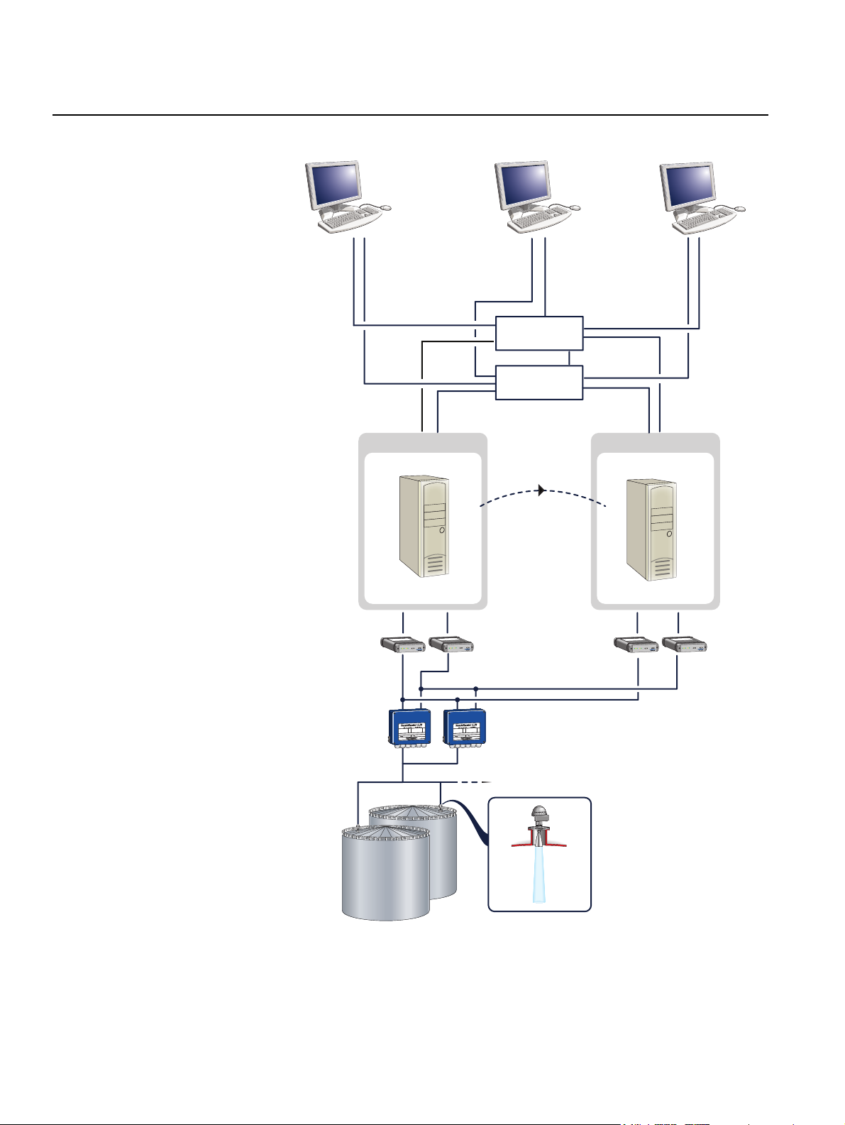
A complete TankMaster Redundancy system consists of two Tank Servers (a
Primary Tank Server and a Backup Tank Server) and a number of Clients
for the operators, see Figure 2-1 on page 2-2.
The Clients are equipped with the graphical user interface WinOpi.
The Tank Server communicates with connected devices and handles
configuration data for all installed tanks and devices. Configuration data and
many other parameters are stored by the Tank Server. The Tank Server polls
data from connected devices and provide these data to the WinOpi/WinSetup
user interface.
In a TankMaster Redundancy system, the two Tank Servers work as “hot
redundancy”, that is tank server data, such as tank information and alarm
limits, is replicated from the Primary Tank Server to the Backup Tank Server
whenever there is a change. Measured values, such as tank level and product
temperature, are polled by the respective Tank Server from the Field
Communication Units (FCUs), see Figure 2-2 on page 2-3.
In case the Primary Server fails, the Backup Server automatically takes over
and works as a Primary Server, see Figure 2-3 on page 2-4. After restart, the
Primary Server is automatically updated with data from the Backup Server.
www.rosemount-tg.com
Page 18
Rosemount TankMaster Redundancy
Figure 2-1. Redundancy system
structure
Reference Manual
303032EN, Edition 3
May 2013
WinOpi WinOpi WinOpi
Switch
Switch
Primary Backup
Replication
of data
r
a
d
Ra
k
n
a
T
t
R
ff
O
M
ER
T
-
n
Rx
O
Tx
i
H
-
N
USB
AI
G
RS-232
-
o
Ext. pwr
L
2180
M
B
F
ff
O
M
ER
T
-
n
Rx
O
Tx
i
H
-
N
USB
AI
G
RS-232
-
o
Ext. pwr
L
2180
M
B
F
oun
r
m
a
e
d
s
o
Ra
R
k
n
a
T
t
n
u
o
m
e
os
r
a
d
Ra
k
n
a
T
t
oun
m
e
s
o
R
Rx
Tx
USB
G
RS-232
-
o
Ext. pwr
L
2180
M
B
F
r
a
d
Ra
k
n
a
T
t
n
u
o
m
e
s
o
R
FBMFBMFBMFBM
f
f
O
M
ER
T
-
n
Rx
O
Tx
i
H
-
N
USB
f
f
AI
O
G
RS-232
-
-
M
o
Ext. pwr
L
ER
T
n
O
i
H
N
AI
0
218
M
B
F
FCUFCU
2-2
Section 2. System Overview
Page 19

Reference Manual
303032EN, Edition 3
May 2013
Rosemount TankMaster Redundancy
2.1 NORMAL OPERATION
Figure 2-2. Normal operation
During normal operation, see Figure 2-2, the Tank Servers poll ordinary
process data from the FCUs. The Primary Server replicates configuration
data to the Backup Server.
WinOpi
Primary Backup
Replication
WinOpi WinOpi
of data
Section 2. System Overview
FCU
The Client workstations, which are used by the operators, are connected
through a Local Area Network (LAN) both to the Primary Server and to the
Backup Server.
At a failure, the active connection is transferred to the Backup Server, which
will then take over the role as the Primary Tank Server, see Figure 2-3.
2-3
Page 20
Rosemount TankMaster Redundancy
Reference Manual
303032EN, Edition 3
May 2013
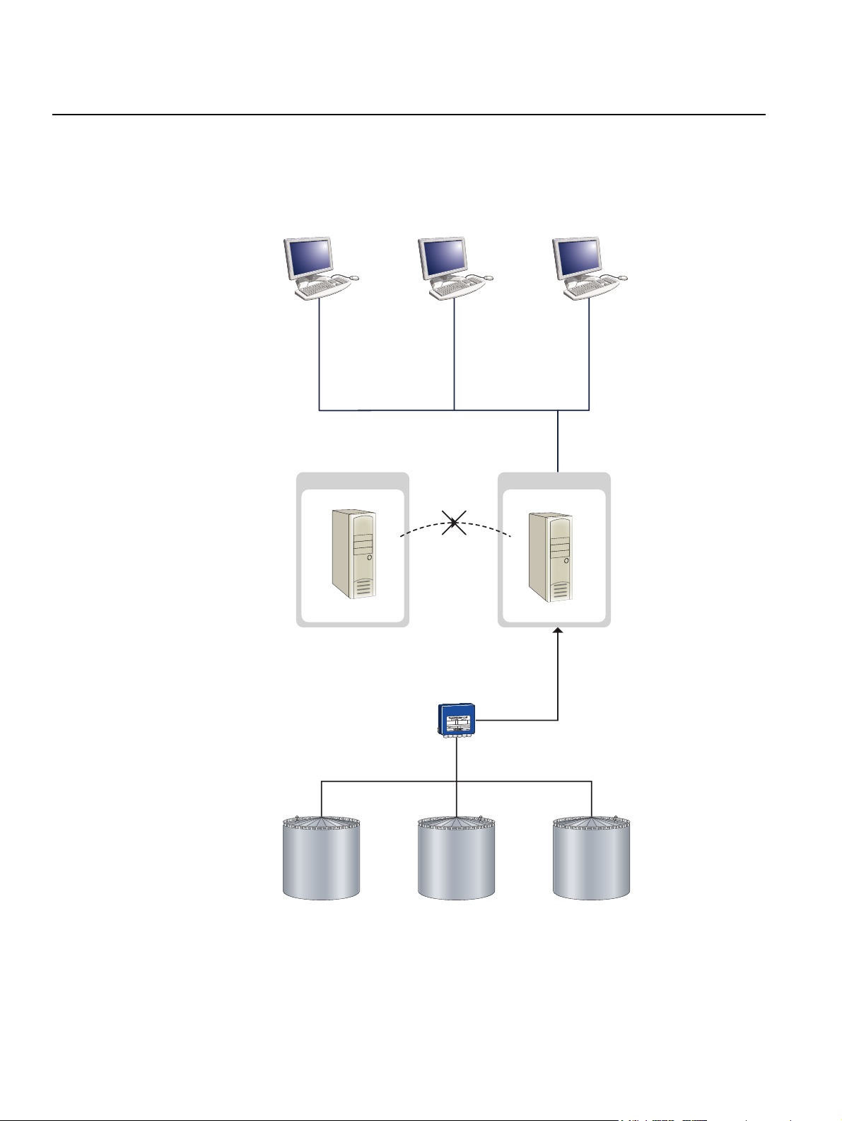
2.2 BACKUP OPERATION
Figure 2-3. Backup operation
After a Failover is performed (see “Failover” on page 2-5), the Backup Server
acts as the Primary server. It maintains the network connections to the
WinOpi clients and polls level data from the FCUs.
WinOpi WinOpi WinOpi
Primary Backup
No replication
2-4
FCU
When the Primary Server has recovered and is online again, it is updated with
all data stored in the Backup Server database.
Section 2. System Overview
Page 21

Reference Manual
303032EN, Edition 3
May 2013
Figure 2-4. Icon in WinOpi
Rosemount TankMaster Redundancy
The following happens when a failure occurs and the Primary Server fails:
1. A message is sent to all clients running WinOpi, that the Primary Server
is offline and the Backup Server is the new primary Tank Server.
2. The Primary Server icon changes and is equipped with a yellow
exclamation mark to indicate a failure.
3. Automatic Failover to Server B is performed.
Failover
Failover is a script that is performed automatically when a failure on Server A
is detected. It redirects network links from Server A to Server B.
Failover can also be performed manually, for example when a Tank Server
needs service.
When Server A is restarted, it tries to establish the Normal Operation mode.
If Normal Operation mode cannot be restored, a manual Failover must be
performed.
Section 2. System Overview
2-5
Page 22

Rosemount TankMaster Redundancy
Reference Manual
303032EN, Edition 3
May 2013
2.3 SERVICE OPERATION
Figure 2-5. Service operation
Service work is always performed on the server in backup mode.
If service work is to be performed on the Primary Server, a manual Failover
must be accomplished before the server can be shutdown, see “Service” on
page 4-7.
WinOpi WinOpi WinOpi
Primary Backup
No replication
FCU
When the disconnected Tank Server is back online, the active Tank Server
sends an update of collected data. After service, the system is restored to
normal operation, see “Normal Operation” on page 2-3.
2-6
Section 2. System Overview
Page 23

Reference Manual
303032EN, Edition 3
May 2013
Section 3 Installation
3.1 Windows Configuration . . . . . . . . . . . . . . . . . . . . . . page 3-3
3.2 Time Server Installation . . . . . . . . . . . . . . . . . . . . . . page 3-15
3.3 Client and WinOpi Installation . . . . . . . . . . . . . . . . . page 3-18
3.4 Redundant Network configuration . . . . . . . . . . . . . page 3-20
The installation is divided into four parts:
• The first part includes general Windows settings, such as network
installation and configuration, firewall configuration, and also to verify
the TankMaster installation.
• The second part includes the Windows time server configuration.
• The third part includes the Windows time client and WinOpi
configuration.
• The fourth and final chapter contains what is required for a redundant
network and how it is configured.
Rosemount TankMaster Redundancy
www.rosemount-tg.com
Page 24

Rosemount TankMaster Redundancy
In this chapter, the following network topology will be used for the TankMaster
Redundancy system.
Reference Manual
303032EN, Edition 3
May 2013
Figure 3-6. Network topology
192.168.10.100
WinOpi
.
WinOpi
192.168.10.101
Switch A Switch B
192.168.10.51 192.168.10.52
Server A
192.168.10.2 192.168.10.3
Firewall
WinOpi
192.168.10.102
Server B
Existing LAN
at Customer
WinOpi
192.168.100.100 192.168.100.101
WinOpi
The IP addresses used in Figure 3-1 is an example and may vary.
NOTE!
Basic knowledge about Local Area Network (LAN) is required for installation
of the TankMaster Redundancy System.
NOTE!
In the following description the Primary Server is referred to as Server A and
the Backup Server as Server B.
3-2
Section 3. Installation
Page 25

Reference Manual
303032EN, Edition 3
May 2013
Rosemount TankMaster Redundancy
3.1 WINDOWS CONFIGURATION
This chapter applies to both the servers and the clients.
1. Windows network configuration, see Windows network configuration
on page 3-3.
2. Configure regional and language settings, see Configure regional and
language settings on page 3-5.
3. Installation and configuration of the network cards, see Redundant
network cards on page 3-6.
4. TankMaster installation, see TankMaster installation on page 3-10.
5. Windows firewall configuration, see Configuring the Windows Firewall
on page 3-10.
6. Folder access, see Access permission on shared folder TM on
page 3-13.
3.1.1 Windows network configuration
Before installing TankMaster, it must be decided if a domain or a workgroup
should be used.
A workgroup is the simplest alternative and does not require a separate logon
server, but the same Windows user name and password must be used on all
connected computers. This because the matching of the user is done locally
in the server. If different user names are used, WinOpi produces an Access
denied error message at connection time.
On a domain, different Windows user names can be used as long as they are
members of the same domain. A domain requires a separate domain server.
Workgroup
When installing TankMaster in a workgroup, perform the following steps:
• Create a Windows user name with administrator rights on all servers
and clients.
User name: TMSystem
Password: TankMaster
• Configure all servers and clients to auto logon on Windows with the
newly created user name TMSystem, see Configure auto logon in a
Workgroup on page 3-4
• Restart and verify that the automatic logon works.
Section 3. Installation
3-3
Page 26

Rosemount TankMaster Redundancy
Configure auto logon in a Workgroup
It is recommended to use the auto logon feature on all servers and dedicated
WinOpi clients.
1. Press the Windows logo key + r to access the Run command.
Type control userpasswords2 in the Open field, click OK.
2. Clear the check box Users must enter a user name and password to
use this computer and click Apply.
Reference Manual
303032EN, Edition 3
May 2013
3-4
3. When the Apply button is pressed, the Automatically Log On window will
appear. Enter TMSystem in the User name field and TankMaster in the
Password field. Confirm the password. Click the OK button.
Section 3. Installation
Page 27

Reference Manual
303032EN, Edition 3
May 2013
Rosemount TankMaster Redundancy
Domain
NOTE!
It is recommended that the same Windows user name is used on all
TankMaster Servers and dedicated WinOpi clients.
When installing TankMaster in a domain, perform the following steps:
• Create a Windows user name with administrator rights on the domain
server. The user shall have Administrators right on the local computer.
User name: TMSystem
Password: TankMaster
• Configure all servers and clients to auto logon on Windows with the
newly created user name TMSystem, see Configure auto logon for a
Domain on page 3-5
• Restart and verify that the automatic logon works.
Configure auto logon for a Domain
If more than one domain servers are present, it is important that the
TankMaster servers and the WinOpi clients are connected to the same
domain.
All TankMaster servers should enable auto logon to Windows at startup. It is
also recommended that all dedicated WinOpi clients have auto logon enabled
as well, this since reports and alarms are created on the clients. To enable the
auto logon feature in a domain, create a file in Notepad and save it as
AutoLogon.reg. Enter the following in the file:
REGEDIT4
[HKEY_LOCAL_MACHINE\SOFTWARE\Microsoft\Wndows
NT\CurrentVersion\Winlogon]
“DefaultUserName”=”WINDOWS_DOMAIN_USER_NAME”
“DefaultPassword”=”WINDOWS_DOMAIN_PASSWORD”
“AutoAdminLogon”=”1”
Change the WINDOWS_DOMAIN_USER_NAME and
WINDOWS_DOMAIN_PASSWORD to the newly created user name and
password. Save and run the AutoLogon.reg file.
3.1.2 Configure regional and language settings
From the Control Panel, click Region and Language.
• Verify that all the computers use the same location.
Section 3. Installation
3-5
Page 28
Rosemount TankMaster Redundancy
3.1.3 Redundant network cards
NOTE!
Follow this section only when redundant network cards are to be used.
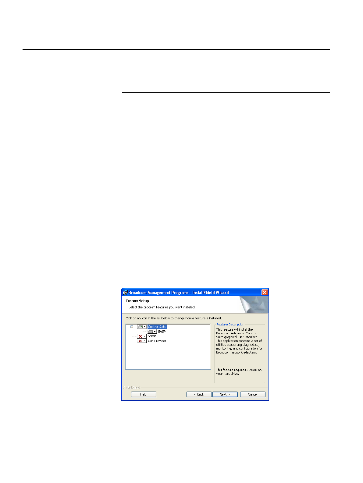
For a redundant network, a technique called smart load balancing is used on
the network cards. This solution allows the use of two network cards sharing a
single IP address. If either of the network cards or cables malfunction, the
other one will take over with minimal time delay. The software required for this
operation is Broadcom Advanced Control Suit 2 (BACS) and Broadcom
Advanced Server Program (BASP). The latter allows several network cards to
work in a team to be seen by the operating system as a single virtual network
adaptor.
Required hardware
BASP requires that the network adapters are based on the BCM57xx chip.
Hardware installation
Install two network cards in every computer used for the TankMaster setup.
Reference Manual
303032EN, Edition 3
May 2013
Install Drivers for network adapters
The operating system should find and install appropriate driver for the network
cards. If not, use the supplied CD from the manufacturer.
Install BACS
Insert the Broadcom NetXtreme Gigabit Ethernet Driver Software
Release CD.
Click Management Applications, read through the license agreement and
accept.
3-6
Click Next and Finish to complete the installation.
Section 3. Installation
Page 29

Reference Manual
303032EN, Edition 3
May 2013
Table 3-1. Sample configuration
Rosemount TankMaster Redundancy
Configuring BACS
Start BACS from the Control Panel. Click Tools and Create Team to
configure a team. Use the following configuration parameters:
• Team name: LanTeam
• Add two network adapters to the team. Only the adapters based on
Broadcom 57xx chip may be added.
NOTE!
Enable LiveLink. Use the following probe targets and member IP addresses.
Probe Targets Member IP Addresses
Server A 192.168.10.3,
192.168.10.51,
192.168.10.200,
192.168.10.201
192.168.10.52
Server B 192.168.100.2,
192.168.100.51,
192.168.10.202,
192.168.10.203,
192.168.100.52
Operator Station 1 192.168.10.2,
192.168.10.3,
192.168.10.204,
192.168.10.205
192.168.10.51
Operator Station 2 192.168.10.2,
192.168.10.3,
192.168.10.206,
192.168.10.207
192.168.10.51
The Probe Targets are the IP numbers the BASP uses to verify the
connection of the network. If BASP does not receive replies from any of the
specified Probe Targets, BASP assumes that the network is down.
The Member IP addresses are used internally by BASP, they are not seen
anywhere else.
Section 3. Installation
3-7
Page 30

Rosemount TankMaster Redundancy
Configuring IP number for virtual adapter
When the configuration of BACS is complete, a virtual adapter with the team
name will appear in the Network Connections window.
To configure a static IP number to the virtual adapter, perform the following
steps:
1. From the Control Panel open the Network and Sharing Center and
choose Change adapter settings in the left pane.
2. Right click on the Local Area Connection and choose Properties.
Reference Manual
303032EN, Edition 3
May 2013
3. Select Internet Protocol Version 4 (TCP/IPv4) and click Properties.
3-8
Section 3. Installation
Page 31

Reference Manual
303032EN, Edition 3
May 2013
Rosemount TankMaster Redundancy
4. Enable Use the following IP address and type the desired IP number
and Subnet mask. The default gateway can be left blank.
Monitoring network connections using BACS
This is a screen shot of BACS during normal operation.
If a network card has lost the network connection the icon will change to
Section 3. Installation
3-9
Page 32

Rosemount TankMaster Redundancy
Reference Manual
303032EN, Edition 3
May 2013
3.1.4 TankMaster installation
1. Attach a hardware key with the inventory, network and redundancy
options enabled to the PCs.
2. Connect the server PCs, Server A and Server B, to the network switches
and to the FCU/FCUs.
3. Install Rosemount TankMaster on both PCs, Server A and Server B, see
chapter 1.3 (and TankMaster WinSetup User’s Guide).
At installation, the folder Rosemount is created in the root directory, and within
this folder the TankMaster program folder is placed:
C:\Rosemount\TankMaster
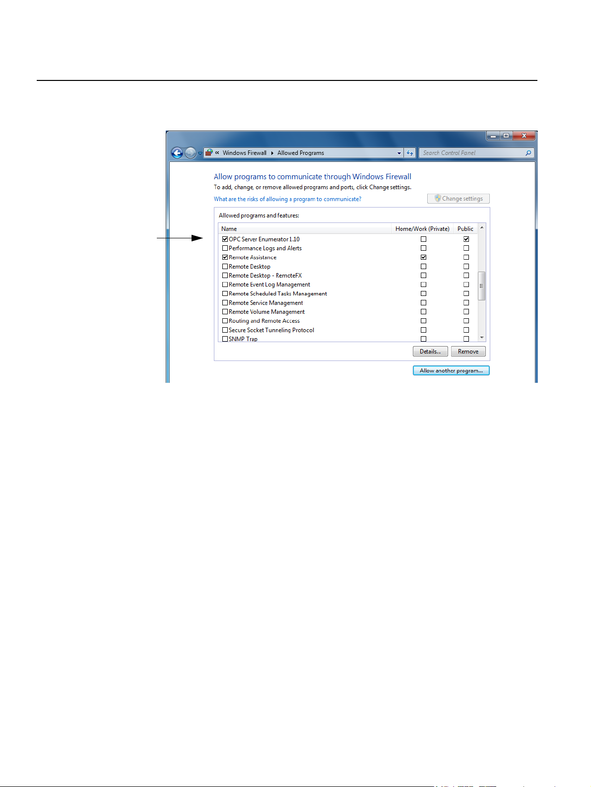
3.1.5 Configuring the Windows Firewall
1. Open Windows Firewall from the Control panel.
2. Select Allow a program through Windows Firewall in the left pane.
3. Click on Change settings.
3-10
4. Click on Allow another program... to enable communication for needed
system and program files. The window Add a Program turns up.
Use the Browse button to locate the files to add. Start with adding
needed Windows system files from the Windows System32 folder, and
continue with the TankMaster files from the Rosemount folder.
Section 3. Installation
Page 33

Reference Manual
303032EN, Edition 3
May 2013
Rosemount TankMaster Redundancy
5. Press the Browse button. Locate the file
C:\Windows\System32\OPCENUM.EXE and press the Open button.
6. In the Add a Program window, mark the file to be added and press Add.
Section 3. Installation
3-11
Page 34
Rosemount TankMaster Redundancy
7. The added file is now allowed through the Firewall and checked on the
list in the Allowed Programs window.
Reference Manual
303032EN, Edition 3
May 2013
8. Repeat step 4—7 for the following files.
• C:\Windows\System32\mmc.exe
• C:\Rosemount\TankMaster\Server\TankServer.exe
• C:\Rosemount\TankMaster\Server\BatchServer.exe
• C:\Rosemount\TankMaster\Server\ModbusMaster.exe
• C:\Rosemount\TankMaster\Server\IOTMaster.exe
• C:\Rosemount\TankMaster\Server\enrafgpuMaster.exe
• C:\Rosemount\TankMaster\Server\ModbusSlave.exe
• C:\Rosemount\TankMaster\Server\DataHighwaySlave.exe
• C:\Rosemount\TankMaster\Server\AsciiLTSlave.exe
• C:\Rosemount\TankMaster\Opi\StmOpi.exe
• C:\Rosemount\TankMaster\Setup\StmSetup.exe
9. Click the OK button to close the Firewall window.
10. Make the same Firewall configuration changes in the Backup Server
and in all Clients, to allow communication between the Servers and the
Clients in the TankMaster network.
3-12
Section 3. Installation
Page 35

Reference Manual
303032EN, Edition 3
May 2013
3.1.6 Access permission on shared folder TM
Depending on if the computer is connected to a domain or a workgroup, the
procedure to grant access to folders is different.
To verify the access permission on the TankMaster folder, browse via
Windows Explorer to C:\Rosemount\ and right click on the TankMaster folder.
Choose Properties and then the menus Sharing and Security from the
popup menu.
Rosemount TankMaster Redundancy
Section 3. Installation
Click on Advanced sharing... and set the name of the shared folder in the
Advanced Sharing window.
Click on Permissions to access the window where to grant access for users.
3-13
Page 36

Rosemount TankMaster Redundancy
Workgroup
Add groups or user names and set up their permissions in the window
Permissions for TM
Reference Manual
303032EN, Edition 3
May 2013
Domain
Verify that the group Everyone has the check box Full Control enabled.
NOTE!
Since Everyone includes all authenticated users, it is often desirable to give
these permissions to a smaller subset of users. A way to accomplish this is to
add all TankMaster users to a group, and give just this group Fully Control to
the shared folder TM.
3-14
Section 3. Installation
Page 37

Reference Manual
303032EN, Edition 3
May 2013
3.2 TIME SERVER INSTALLATION
It is recommended to configure all nodes to synchronize the system time with
the same source.
Define one node to be the TankMaster time server (for example, the Primary
Server in a redundant system). All other TM nodes, including Server-B, must
synchronize the computer system time with the time server.
On the time server, a firewall port must be opened for the clients to be able to
receive the current time. Perform the following:
1. From the Control Panel, on the time server, click the Windows Firewall
icon.
2. In the left pane, click Advanced security.
3. The Windows Firewall with Advanced Security dialog box is shown.
In the left pane, click Inbound Rules.
Rosemount TankMaster Redundancy
Section 3. Installation
4. Then, in the right pane, click New Rule.
5. Follow the instructions in the New Inbound Rule Wizard to configure a
port for time syncronization through the firewall.
3-15
Page 38

Rosemount TankMaster Redundancy
6. Set Rule Type to Port, and press Next.
7. Choose UDP protocol, and specify the Port number (123). Press Next.
Reference Manual
303032EN, Edition 3
May 2013
3-16
8. Allow the connection, and press Next.
Section 3. Installation
Page 39

Reference Manual
303032EN, Edition 3
May 2013
Rosemount TankMaster Redundancy
9. Specify in the Profile in which domain the computer works. Press Next.
10. Enter the name of the Rule: Timeserver
and, optionally, a description of it.
Section 3. Installation
11. Click Finish and close the Firewall configuration window.
The configuration files are located in the Time Synchronization directory on
the TankMaster CD.
1. Run the TM_SetAsClockServer.reg
2. Run the TM_StartClockServer.bat
3. Restart the computer in order to apply settings.
3-17
Page 40

Rosemount TankMaster Redundancy
3.3 CLIENT AND WINOPI INSTALLATION
1. Configure Time Synchronization Client.
2. Connect WinOpi to the Primary Server.
3.3.1 Configure Time Synchronization Client
1. Copy files TM_SetAsClockClient.reg and
TM_StartAndSyncClockClient.bat from the TankMaster CD to the
TankMaster directory (C:\Rosemount\TankMaster).
2. Open the TM_SetAsClockClient.reg with Notepad.
3. Edit row “NtpServer”=”TM_MASTER_CLOCK_NODE,0x1”. Change
TM_MASTER_CLOCK_NODE to the TankMaster time server node
name.
Example: "NtpServer"="SERVER-A,0x1"
4. Edit row “0”=”TM_MASTER_CLOCK_NODE”. Change
TM_MASTER_CLOCK_NODE to the TankMaster time server node
name.
Example: “0“=”SERVER-A”
5. Save the file.
6. Run the TM_SetAsClockClient.reg by double clicking the file.
7. Run the TM_startAndSyncClockClient.bat by double clicking the file.
8. Restart the computer in order to apply settings.
Reference Manual
303032EN, Edition 3
May 2013
On all other TM client nodes, browse via the network to the first client node
where the modified file is located and repeat point 6 and 7. This will enable
the time client on the local computer.
3-18
Section 3. Installation
Page 41

Reference Manual
303032EN, Edition 3
May 2013
3.3.2 Configure WinOpi Client
All WinOpi Clients must be connected to the Primary Server (Server-A). This
is accomplished by performing the following steps:
1. Open the WinOpi Workspace on the Client. Select the Plants view.
2. Right-click on Plants and select New connection.
3. Click Browse and select the computer used as the Primary Server.
Rosemount TankMaster Redundancy
Type the desired Plant name to appear in the WinOpi workspace.
Enter the Alias name that will be used for the Primary Server in the
WinOpi workspace, see WinOPI Tools/Options for more information.
Click OK when done.
Section 3. Installation
3-19
Page 42

Rosemount TankMaster Redundancy
3.4 REDUNDANT NETWORK CONFIGURATION
Since the redundant configuration creates a loop between the two switches,
see Figure 3-6 on page 3-2, a Spanning Tree Protocol (STP) must be used.
The STP is designed for networks with multiple paths and prevents flooding of
the network. There are three different versions of the STP:
• STP (IEEE 802.1d, Spanning Tree Protocol). This is an obsolete
protocol. The convergence time is 30 to 50 seconds.
• RSTP (IEEE 802.1w, Rapid [convergence] Spanning Tree Protocol).
The convergence time is 1 to 3 seconds.
• MSTP (IEEE 802.1s Multiple Spanning Tree Protocol). This is a further
development of RSTP which supports Spanning Tree Protocol in
Multiple Virtual Networks environment.
For minimal time delay if any switch fails the RSTP must be used.
For even quicker response times when a network failure is detected a
technique called Edge is used. The edge port concept means that ports
directly connected to end stations cannot create bridging loops in a network
and can thus directly transition to forwarding, skipping the lengthy listening
and learning stages. Edge ports that receive configuration messages
immediately lose their edge port status and become normal spanning tree
ports. A loop created on an improperly connected edge port is thus quickly
repaired.
Reference Manual
303032EN, Edition 3
May 2013
3-20
Section 3. Installation
Page 43
Reference Manual
303032EN, Edition 3
May 2013
Rosemount TankMaster Redundancy
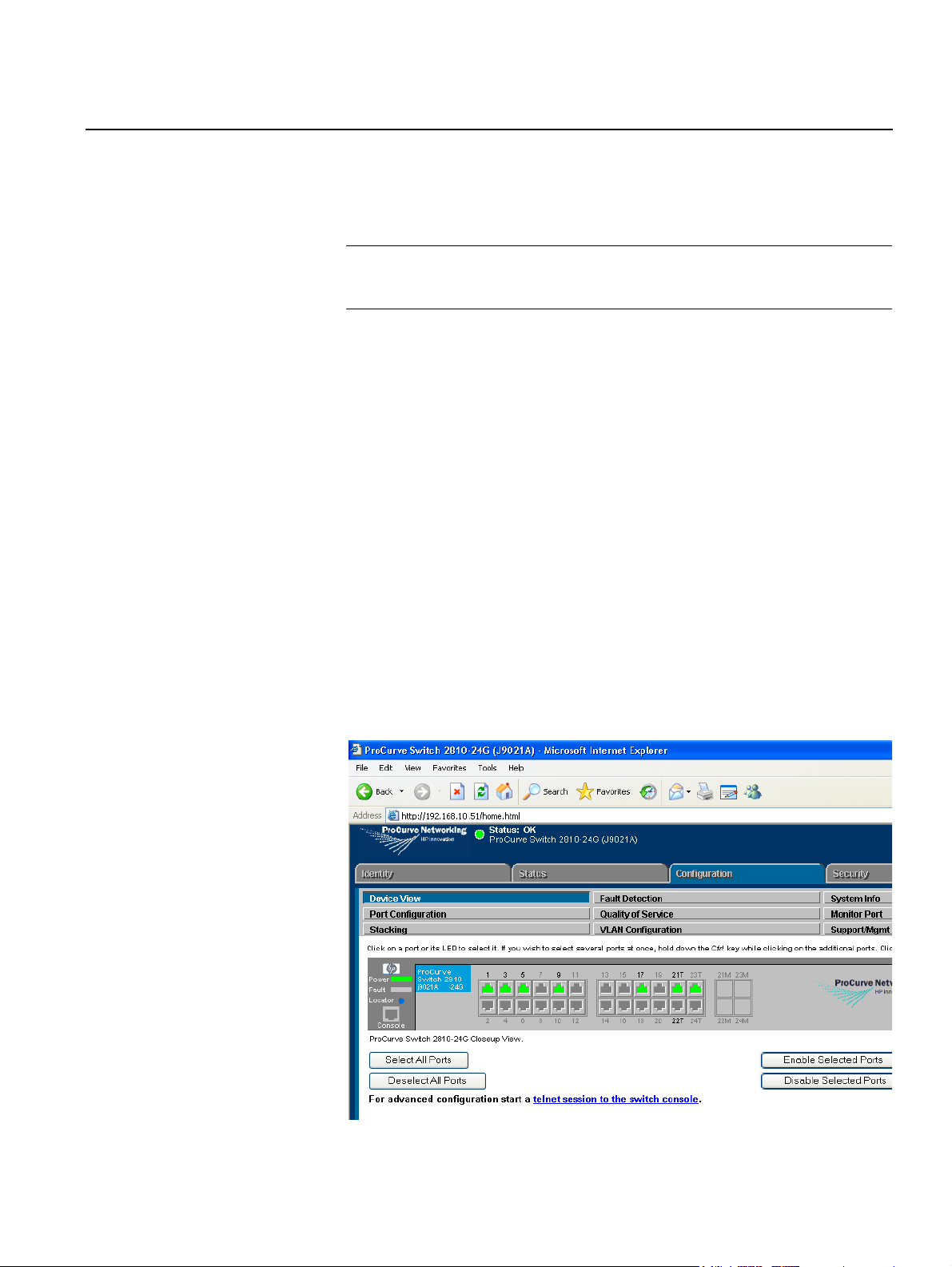
3.4.1 Switch The following chapter describes how to configure RSTP and Edge for the HP
ProCurve 2810 switch.
HP ProCurve 2810
NOTE!
All documents referred to in this chapter are enclosed with the HP ProCurve
switch.
How to connect and assign IP address to the switch is described in Quick
Installation Guide for the ProCurve Series 2810 Switches in the following
chapters:
• Chapter Install the Switch, sub chapter Connect a Console to the
Switch.
• Chapter Configuring the Switch.
Spanning Tree Configuration
As described in Advanced Traffic Guide for the ProCurve Series 2810
Switches, chapter Multiple Instance Spanning-Tree Operation, this
configuration is only available using a CLI (Command Line Interface).
1. Start Internet Explorer. In the address field, enter the IP number of the
HP ProCurve switch. In this example 192.168.10.51.
2. In the Configuration tab select telnet session to the switch console.
3. Enter the following:
configure
spanning-tree
spanning-tree 1-20 edge-port
Section 3. Installation
3-21
Page 44

Rosemount TankMaster Redundancy
Reference Manual
303032EN, Edition 3
May 2013
3-22
Section 3. Installation
Page 45
Reference Manual
303032EN, Edition 3
May 2013
Section 4 Operation
4.1 Administrator program . . . . . . . . . . . . . . . . . . . . . . . page 4-1
4.2 WinOpi . . . . . . . . . . . . . . . . . . . . . . . . . . . . . . . . . . . . page 4-4
4.3 General failures . . . . . . . . . . . . . . . . . . . . . . . . . . . . page 4-5
4.4 Server case scenarios . . . . . . . . . . . . . . . . . . . . . . . page 4-6
4.5 Service . . . . . . . . . . . . . . . . . . . . . . . . . . . . . . . . . . . . page 4-7
4.6 Server status . . . . . . . . . . . . . . . . . . . . . . . . . . . . . . . page 4-8
Rosemount TankMaster Redundancy
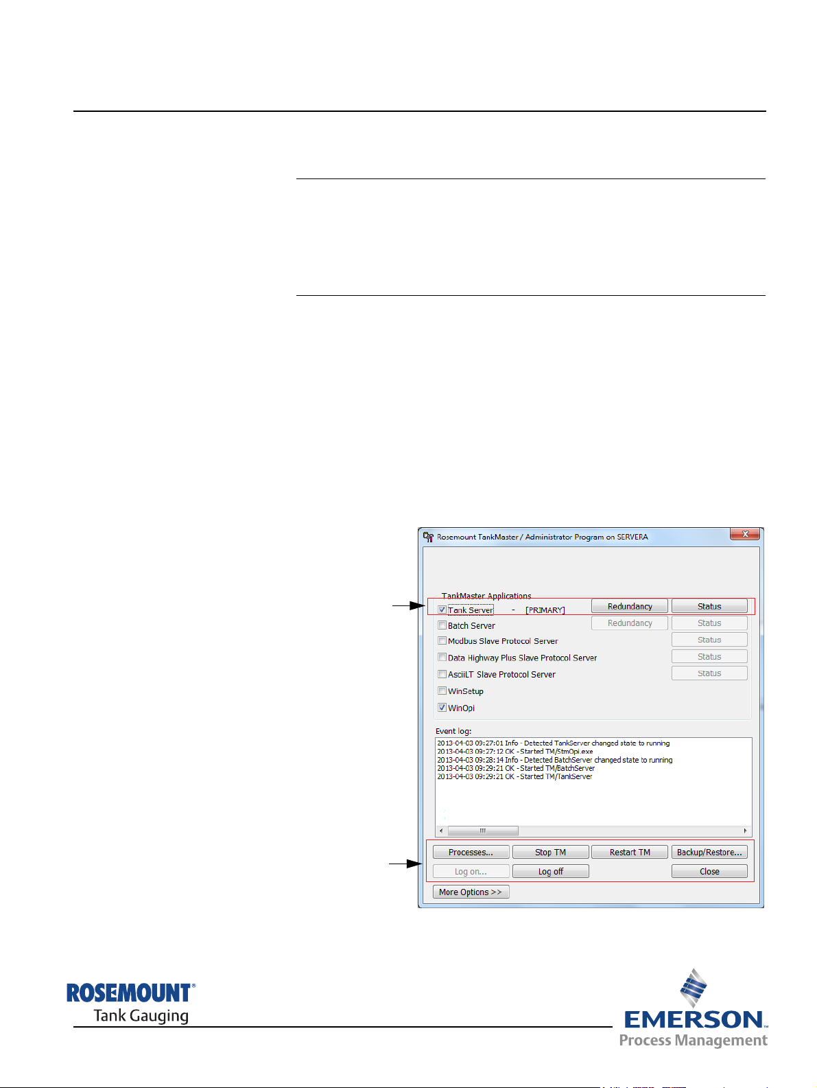
4.1 ADMINISTRATOR PROGRAM
When the TankMaster Redundancy has been installed, the Administrator
program is enhanced with several functions, for example an alive indication
(each five seconds), the Failover functionality, and PRIMARY/BACKUP mode
indication.
Failover is a script that is performed automatically when a failure on the
Primary Server is detected. It redirects network links from the Primary Server
to the Backup Server.
Failover can be performed manually, for example when a TankMaster server
needs service. Failover is also used to restore from backup mode to normal
mode. Click the Redundancy button to open the current status window. Then
click the Failover button to perform a manual Failover.
TankMaster Redundancy
www.rosemount-tg.com
Control buttons
Page 46

Rosemount TankMaster Redundancy
4.1.1 TankMaster Redundancy
Tank Server The check box indicates that TankMaster Server
Reference Manual
303032EN, Edition 3
May 2013
is in operation.
4.1.2 The control buttons
[PRIMARY] /
[BACKUP]
Redundancy button Opens the Redundancy window. Ability to
Status button Opens the Server Status window with general
Processes View all running TankMaster processes.
Stop TM Stop the TankMaster system.
Restart TM Restart the TankMaster system.
Backup/Restore Open the Backup configuration window.
Log on Log on to the Administrator Program.
Log off Log off from the Administrator Program.
Close Close the window.
Indicates whether the TankMaster Server is in
Primary mode or Backup mode.
perform a Failover and correct a database
synchronization problem.
information about TankMaster and server status.
More Options >> View more Options.
Auto Start Config... Open the Auto Start Configuration window.
Fail Over Servers Switch over all enabled servers in a sequence to
the Backup server.
File Details... View all files installed under TankMaster.
Process Affinity... Open the Process Affinity window.
Change Password... Open the PW change window.
Debug Report... Possibility to create mini dumps for some
processes.
NOTE!
The Administrator program on the Backup Server does not know the current
status of the Primary Server, only that the Primary Server is running.
4-2
Section 4. Operation
Page 47
Reference Manual
303032EN, Edition 3
May 2013
Rosemount TankMaster Redundancy
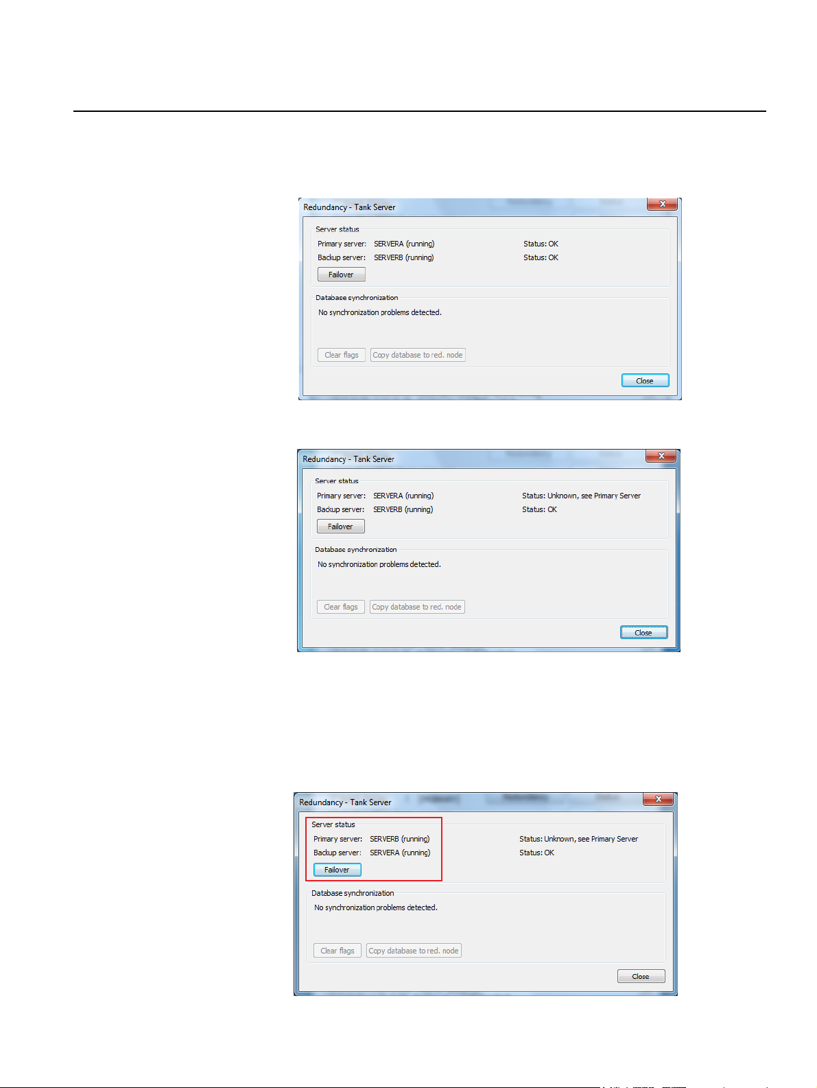
4.1.3 Redundancy
window
Click the Redundancy button and log in as Administrator to the TankMaster
Administrator program to see which server that is in charge. The Redundancy
window shows the following when the Primary Server is in charge:
On the Backup Server, the Redundancy window shows the following:
Section 4. Operation
From the Redundancy window it is possible to manually initiate a Failover
from the current server (SERVER-A) to the redundant server (SERVER-B), by
clicking the Failover button (turns active when the cursor moves over it).
When the Failover is performed, the message “Command completed
successfully!” is shown on both the Primary Server and the Backup Server,
and information in the Redundancy window has changed. SERVER-A shows:
4-3
Page 48

Reference Manual
303032EN, Edition 3
Rosemount TankMaster Redundancy
4.2 WINOPI
4.2.1 Redundancy When a server is running in redundant mode the icon changes to a
“double-computer” icon, see below. Local Server (SERVER-A) is the Primary
Server with SERVER-B as the redundant Backup Server.
May 2013
4.2.2 Messages and alerts
Whenever there is a status change of the redundant servers, a message is
sent to all WinOpi clients.
To alert the operator there has been a failure, there is also an error message
presented at the bottom of the WinOpi client window.
Also the “double-computer” icon shows an alert to indicate that the Backup
server has taken over from SERVER-A.
4-4
Backup server alert
Section 4. Operation
Page 49

Reference Manual
303032EN, Edition 3
May 2013
4.3 GENERAL FAILURES
Rosemount TankMaster Redundancy
The Primary Server may become unavailable for various reasons, such as:
• Power failure
• Hardware failure
• System hanging
• Other system failures resulting in a non-responding system or network
disruption
When the Primary Server fails, the Backup Server will take over within 30
seconds.
During Failover the operator may experience a short delay before the Client
has connected to the Backup Server.
Once a server (Primary or Backup) is unavailable, a message will appear in
the status bar of the WinOpi, informing the operator which server has failed.
It is important that a failed server is restored as soon as possible, to quickly
resume the redundancy functionality.
Section 4. Operation
4-5
Page 50

Rosemount TankMaster Redundancy
4.4 SERVER CASE SCENARIOS
4.4.1 Primary Server failed resulting in a Failover
Verify that the Backup Server is acting as Primary Server. Check the network
connections to make sure they are connected properly. Reboot the former
Primary Server (SERVER-A).
When SERVER-A starts, it should enter Backup mode. Verify that no
database synchronization problem exists, see “Database synchronization
problems” on page 4-7, and perform a manual Failover.
4.4.2 Backup Server has failed but Primary Server is still running
Check all network connections to make sure that they are connected properly.
If two primary servers are present, see “Server failure resulting in two Primary
Servers” on page 4-6. Reboot SERVER-B and wait until it is reloaded.
Verify in the TankMaster Administrator program that everything is loaded and
the status of SERVER-B is BACKUP. Also check the TankMaster
Administrator program Event log that no errors are present.
Reference Manual
303032EN, Edition 3
May 2013
On Server A: In the TankMaster Administrator program, click the
Redundancy button. The status of both Primary Server and Backup Server
should be OK, see “Redundancy window” on page 4-3.
Verify that no synchronization problems are present in the TankMaster
Administrator program Event log. If synchronization problems are present,
see “Database synchronization problems” on page 4-7.
4.4.3 Server failure resulting in two Primary Servers
In case of network problems to the Primary Server (SERVER-A), the Backup
Server will take over resulting in two primary servers. If this occurs it is
important to restore network connections to both servers.
When both servers are running as Primary Servers, database synchronization
error may occur.
To verify no database synchronization problem exits, click the Redundancy
button in the TankMaster Administrator program.
In the Database synchronization group box, the status of the database is
presented. If database synchronization problems are present, see “Database
synchronization problems” on page 4-7.
4-6
Section 4. Operation
Page 51

Reference Manual
303032EN, Edition 3
May 2013
4.4.4 Database synchronization problems
From the TankMaster Administrator program click the Redundancy button. If
there is a synchronization problem, the registry flags must be cleared.
This is accomplished by clicking the Clear flags button. The flags should be
cleared on both servers. When all flags are cleared, the Backup Server
(SERVER-B) must be restarted. Make sure that SERVER-B enters backup
mode and verify that no errors are present in the TankMaster Administrator
program Event log.
Rosemount TankMaster Redundancy
4.5 SERVICE When performing service work on either server, do the following:
1. Make sure that the server to be shutdown is running in backup mode. If
not, do a manual Failover, see “Administrator program” on page 4-1.
2. Shutdown the server running in backup mode.
3. Perform service work on the server.
4. Start up the server.
5. Check that the server starts in backup mode, see “Administrator
program” on page 4-1
NOTE!
If both servers need service simultaneously, always shutdown the Backup
Server first to avoid synchronization problems. After service, always begin
startup with the server that was the Primary Server before shutdown.
Section 4. Operation
4-7
Page 52

Reference Manual
Rosemount TankMaster Redundancy
303032EN, Edition 3
May 2013
4.6 SERVER STATUS During operation several messages are presented to the user. Examples of
messages are primary failure, backup server status (OK or failure) etc. These
are logged in the OPC Server Information (Status) log.
Right-Click the Redundant Server icon in the TankMaster WinOpi program
and choose Server Status from the popup menu to view the OPC Server
Information log.
The OPI Server information window shows the Status log of the servers:
4-8
Section 4. Operation
Page 53

Reference Manual
303032EN, Edition 3
May 2013
Rosemount TankMaster Redundancy
Section 5 Redundancy checklist
5.1 Verify TankMaster Redundancy . . . . . . . . . . . . . . . . page 5-1
5.2 Verify Network Redundancy . . . . . . . . . . . . . . . . . . page 5-1
5.1 VERIFY TANKMASTER REDUNDANCY
The following chapter describes how to verify the TankMaster system is
redundant.
1. Perform a manual failover (click the Failover button).
2. Verify from a WinOpi client that all tanks are present. If no tanks appear,
perform a manual failover again and reboot SERVER-B (Backup Server).
3. When SERVER-B has restarted, perform a manual failover. If no tanks
are visible despite the restart of the server, verify write access to the
shared TM folder, see “Access permission on shared folder TM” on
page 3-13.
4. When verified that all tanks successfully have been copied to
SERVER-B, make a new manual failover to set the system in normal
operation again. (SERVER-A active, SERVER-B backup.)
5.2 VERIFY NETWORK REDUNDANCY
To ensure that the redundancy of the network has been correctly configured,
preform the following tests.
1. Verify that the primary adapters in BACS do not have any connection
problems. If the adapters are marked with a red cross, connection
problems exist, see “Monitoring network connections using BACS” on
page 3-9.
2. Start TankMaster on all computers and verify network connectivity.
3. While TankMaster is running try the following:
• Temporary power off the switches one by one.
• Disconnect the redundant network cables one by one.
This should result in:
• The status of the network adaptor in BACS changes accordingly.
• TankMaster is not affected by these single points of failures.
NOTE!
Remember to make a 30 seconds pause after the system has recovered from
a single point of failure and before trying a new one.
www.rosemount-tg.com
Page 54

Rosemount TankMaster Redundancy
Reference Manual
303032EN, Edition 3
May 2013
5-2
Section 5. Redundancy checklist
Page 55

Reference Manual
303032EN, Edition 3
May 2013
Rosemount TankMaster Redundancy
Section 6 Trouble Shooting
6.1 DCOM error messages . . . . . . . . . . . . . . . . . . . . . . . page 6-1
6.2 Check Configuration of DCOM settings . . . . . . . . .page 6-2
6.3 WinOpi failures . . . . . . . . . . . . . . . . . . . . . . . . . . . . . page 6-6
6.4 Other . . . . . . . . . . . . . . . . . . . . . . . . . . . . . . . . . . . . . page 6-7
6.1 DCOM ERROR MESSAGES
If the problem is DCOM related, look in the Windows Event Viewer for error
messages. Check the Event viewer for both the Clients and the Servers.
The Event Viewer is located in the Control Panel in Administrative Tools.
6.1.1 Server not available
The message “Server not available” means that the remote computer is down.
The connection timeout can be up to 140—150 seconds depending on the
current network setup.
Example: In case WinOpi is started and one remote server is unavailable,
there is a delay until the error message is presented. The delay is about
140—150 seconds.
6.1.2 Access is denied The message “Access is denied” points to improper configuration of the
DCOM settings.
The message will be presented with no time delay to the user.
6.1.3 Server execution failed
The message “Server execution failed” is presented in case no user is logged
on.
The message will be presented with no time delay to the user.
6.1.4 System message about protocol servers ...
If the system message concerns protocol servers on remote stations, verify
the DCOM configuration, see “Check Configuration of DCOM settings” on
page 6-2.
6.1.5 The object exporter specified was not found
The message “The object exporter specified was not found” means that the
computer has no IP address. This may show up as error code 0x80070776
returned from a failed connection.
www.rosemount-tg.com
Page 56

Rosemount TankMaster Redundancy
6.1.6 The object is disconnected from its clients
DCOM clients ping the server object. In case these pings are undetected by
the server, during approximately 6 minutes, the server disconnects from these
clients. Normally, WinOpi Clients will detect this error and try to re-establish
the connection to the server.
6.2 CHECK CONFIGURATION OF DCOM SETTINGS
Check the DCOM settings, made by the TankMaster Installation program.
1. Press the Windows logo key + r to access the Run command.
Type dcomcnfg in the Open field, and click OK.
Reference Manual
303032EN, Edition 3
May 2013
2. The Component Services window will appear. Double-click on the
Component Services icon and then on the Computers folder icon.
3. Right-click on the icon My Computer and select Properties from the
popup menu.
4. In the Default properties tab, verify that the Enable Distributed COM
on this computer is selected.
6-2
Section 6. Trouble Shooting
Page 57

Reference Manual
303032EN, Edition 3
May 2013
Rosemount TankMaster Redundancy
5. In the COM Security tab, click the Edit Limits button in the Access
Permissions group box.
6. Check that the following groups exist in the field “Groups or user names”:
Everyone; System; Network; Administrators; Performance Log
Users, Distributed COM Users; Interactive; and Anonymous Logon.
7. Make sure that both Local Access and Remote Access are set to Allow
for all the users in the Group or user names list.
Click OK to close current window.
Section 6. Trouble Shooting
6-3
Page 58

Rosemount TankMaster Redundancy
8. If any group is missing, press the Add button, and the Select Users or
Groups window will appear.
Add missing group/s, and click OK.
9. Click the Edit Default button in the Access Permission group box, and
check that the following groups are listed:
Everyone; Self; Network; System; Administrators; Interactive; and
Anonymous Logon.
10. Verify both that Local Access and Remote Access are set to Allow for
all users listed in the Group or user names list.
Click OK to close current window.
11. Click the Edit Limits button in the Launch and Activation Permissions
group box, and check that the following groups are listed:
Everyone; System; Network; Administrators; Performance Log
Users, Distributed COM Users; Interactive; and Anonymous Logon.
12. Make sure all check boxes in the Permissions for are set to Allow for
all users in the Group or user names list.
Click OK to close current window.
13. Click the Edit Default button in the Launch and Activation Permissions
group box and check that the following groups are listed:
Everyone; System; Network; Administrators; Interactive; and
Anonymous Logon.
14. Make sure that all Allow check boxes for all users are checked.
Click OK to close current window.
15. Close the My Computer Properties window using the OK button.
Reference Manual
303032EN, Edition 3
May 2013
6-4
NOTE!
Since Everyone includes all authenticated users, it is often desirable to add
these permissions to a smaller subset of users. A way to accomplish this is to
create a group named TM Users and add all users names to this group that
will execute any OPC Server or Client, for example user TMSystem. Then
substitute TM Users everywhere that Everyone appears in the configuration
dialogs described above. It is also possible to use a specific user, for example
user TMSystem instead of the group Everyone.
Section 6. Trouble Shooting
Page 59
Reference Manual
303032EN, Edition 3
May 2013
Rosemount TankMaster Redundancy
Setting TankMaster permissions
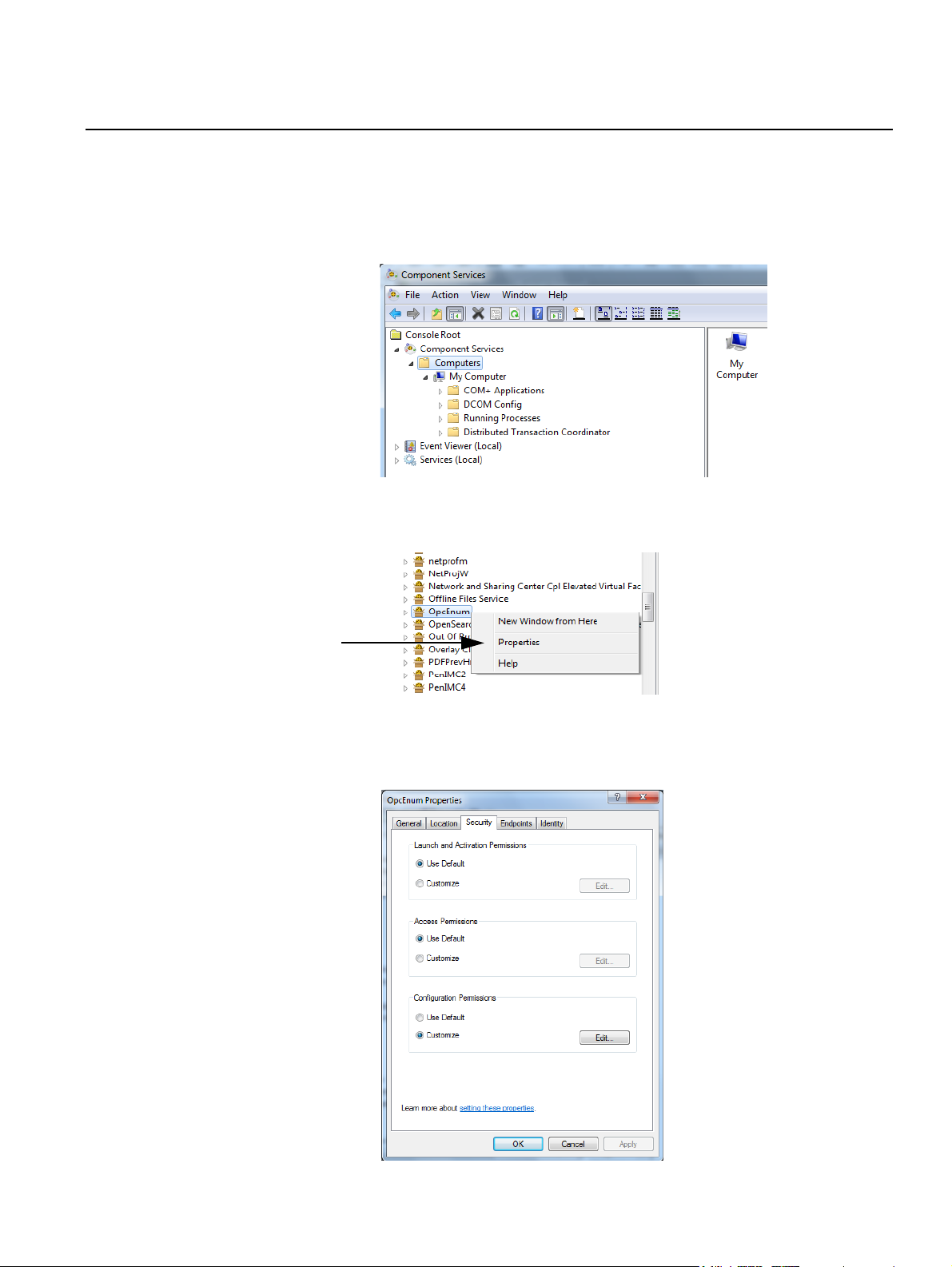
1. Open the Component Service window (Step 1 in the previous section).
2. Double-click the Computer icon and then the icon My Computer.
Expand the DCOM Config folder by double-clicking it.
3. Right-click on the OpcEnum icon, and select Properties from the popup
menu.
4. Check the Security tab, that Launch and Activation Permissions and
Access Permissions are set to Use Default.
Section 6. Trouble Shooting
6-5
Page 60

Rosemount TankMaster Redundancy
5. Click the Edit button for the Configuration Permissions and verify that
the Administrators Group is present in the list.
If not, add the Administrators Group by clicking the Add button.
Click OK to leave current window.
6. In the Identity tab, check that the The interactive user is selected.
Click OK to close the window.
7. If necessary, use the Component Services window and repeat
steps 3 - 6 to check set permissions in the following applications:
• Rosemount\TankMaster\BatchServer OPC Server.
• Rosemount\TankMaster\EnrafGPUaster OPC Server.
• Rosemount\TankMaster\IOTMaster OPC Server.
• Rosemount\TankMaster\ModbusMaster OPC Server.
• Rosemount\TankMaster\TankServer OPC Server.
• COM Server for configuration of TankMaster Ascii Slave protocol.
• COM Server for configuration of TankMaster AsciiLT Slave Protocol.
• COM Server for configuration of TankMaster DataHighway Plus Slave
Protocol.
• COM Server for configuration of TankMaster Modbus Slave Protocol.
• COM Server for configuration of TankMaster ModbusLU Slave
Protocol.
Reference Manual
303032EN, Edition 3
May 2013
6.3 WINOPI FAILURES
6.3.1 No tanks are displayed
If a Failover has occurred and no tanks are displayed in the tank view,
WinOpi must be restarted manually. This behavior may happen if the system
is heavily overloaded during the actual Failover.
6.3.2 Redundancy restored but error message still present
If there has been a Failover and redundancy is restored but the Client still
reports a problem, perform a manual restart of WinOpi.
6-6
Section 6. Trouble Shooting
Page 61
Reference Manual
303032EN, Edition 3
May 2013
Rosemount TankMaster Redundancy
6.4 OTHER
6.4.1 Unable to connect to shared folder TM
When trying to access the shared folder TM an access denied message is
presented. Verify that the user TMSystem has logged in on all computers. If
the problem still exists, try to un-share the TM folder and then re-share it
again, see “Access permission on shared folder TM” on page 3-13.
6.4.2 Database copying problem
If the TankMaster Administrator Event log indicates an error when trying to
copy the database to the Backup Server, there may be an access permission
problem. For verification of the access permission, see “Access permission
on shared folder TM” on page 3-13.
6.4.3 Firewall setup If there are communication problems between the Servers or between any
Server and a Client, check the configuration of Windows Firewall in the
Control Panel, see “Configuring the Windows Firewall” on page 3-10.
6.4.4 Redundancy configuration not correct
If the redundancy between the Primary Server and the Backup Server do not
function correctly, check the redundancy configuration in both servers.
NOTE!
Make sure that the Tank Server on Server B is shut down by checking the
processes in the Administrator Program. Only the Administrator Program
process should be running, see TankMaster WinSetup User’s Guide.
To configure Server A for redundancy do the following:
1. Open the WinOpi Workspace on Server A. Select the Plants view.
Section 6. Trouble Shooting
6-7
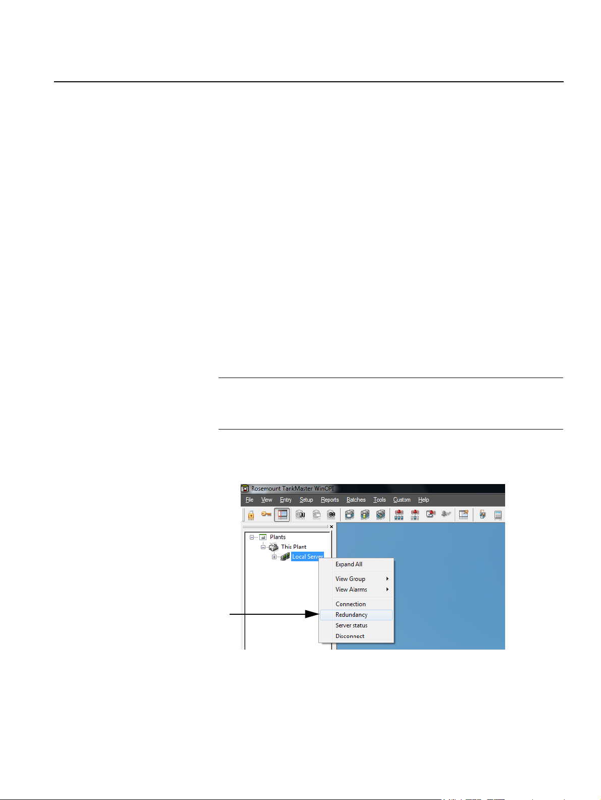
Page 62
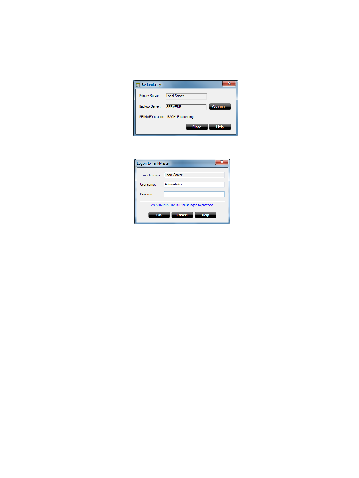
Rosemount TankMaster Redundancy
2. Right-click on the Local Server icon and select Redundancy on the
popup menu to display the current redundancy state.
3. To change server, click the Change button and log in as Administrator.
Reference Manual
303032EN, Edition 3
May 2013
4. Also check the Connections from the popup menu.
As Administrator, it is possible to change, connect and disconnect
Servers and Clients in the TankMaster configuration.
6-8
Section 6. Trouble Shooting
Page 63

Reference Manual
303032EN, Edition 3
May 2013
Rosemount TankMaster Redundancy
Index
A
Acrobat Reader . . . . . . . . . . . . 1-5
Administrator program
B
BACS . . . . . . . . . . . . . . . . . . . . 3-6
BASP
. . . . . . . . . . . . . . . . . . . . 3-6
C
Configure
BACS
. . . . . . . . . . . . . . . . . 3-7
IP number
redundancy
regional and language settings
3-5
Windows network
WinOpi
. . . . . . . . . . . . . . . 3-19
D
Domain
access permission
auto logon
F
Failover . . . . . . . . . . . . . . . 2-5, 4-1
H
Hardware . . . . . . . . . . . . . . . . . 1-4
. . . . . . . 4-1
. . . . . . . . . . . . . 3-8
. . . . . . . . . . . . 6-7
. . . . . . . 3-3
. . . . . . 3-14
. . . . . . . . . . . . . 3-5
Reports
S
Server Hardware Key Info . . . . 1-10
Slave Protocol Server
Software
Spanning Tree
Switch
System Requirements
system requirements
T
Tank Server . . . . . . . . . . . . . . . 1-2
TankMaster
Team name
V
View Server HW Key Info . . . . 1-10
W
Windows
WinOpi
WinSetup
Workgroup
. . . . . . . . . . . . . . . . . . . 6-1
. . . . . . . . 1-2
. . . . . . . . . . . . . . . . . . 1-4
Installation
. . . . . . . . . . . . . 1-5
. . . . . . . . . . . . 3-21
. . . . . . . . . . . . . . . . . . . 3-21
. . . . . . . . 1-4
. . . . . . . . . 1-4
. . . . . . . . . . . . . . . . 1-1
. . . . . . . . . . . . . . . . 3-7
firewall
. . . . . . . . . . . . . . . 3-10
network
. . . . . . . . . . . . . . . 3-3
. . . . . . . . . . . . . . . . . . . 1-2
. . . . . . . . . . . . . . . . . 1-2
access permission
auto logon
. . . . . . . . . . . . . 3-4
. . . . . . 3-13
I
Illegal characters . . . . . . . . . . 1-11
L
LiveLink . . . . . . . . . . . . . . . . . . 3-7
M
Master protocol server . . . . . . . 1-2
O
OPC . . . . . . . . . . . . . . . . . . . . . 1-3
R
Redundant Network . . . . . . . . 3-20
Redundant network cards
www.rosemount-tg.com
. . . . . 3-6
Page 64

Rosemount TankMaster Redundancy
Reference Manual
303032EN, Edition 3
May 2013
Index-2
Page 65

Page 66

Reference Manual
303032EN, Edition 3
May 2013
Rosemount TankMaster Redundancy
Rosemount and the Rosemount logotype are trademarks of Rosemount Inc.
HART is a registered trademark of the HART Communication Foundation.
Modbus is a trademark of Modicon.
Pentium is a trademark of Intel Corporation.
Windows and Microsoft Office are trademarks of Microsoft Corporation.
All other trademarks are the property of their respective owners.
Emerson Process Management
Rosemount Tank Gauging
Box 130 45
SE-402 51 Göteborg
SWEDEN
Tel (International): +46 31 337 00 00
Fax (International): +46 31 25 30 22
E-mail: sales.srt@emersonprocess.com
www.rosemount-tg.com
© 2013 Rosemount Tank Radar AB. All rights reserved.
 Loading...