


Instruction Manual
IB-106-340AC Rev. 1.1
April 2001
SPS 4000
Single Probe
Autocalibration Sequencer
http://www.processanalytic.com

ESSENTIAL INSTRUCTIONS
READ THIS PAGE BEFORE PROCEEDING!
Rosemount Analytical designs, manufactures and tests its products to meet many national and
international standards. Because these instruments are sophisticated technical products, you
MUST properly install, use, and maintain them to ensure they continue to operate within their
normal specifications. The following instructions MUST be adhered to and integrated into your
safety program when installing, using, and maintaining Rosemount Analytical products. Failure to
follow the proper instructions may cause any one of the following situations to occur: Loss of life;
personal injury; property damage; damage to this instrument; and warranty invalidation.
• Read all instructions prior to installing, operating, and servicing the product.
• If you do not understand any of the instructions, contact your Rosemount Analytical repre-
sentative for clarification.
• Follow all warnings, cautions, and instructions marked on and supplied with the product.
• Inform and educate your personnel in the proper installation, operation, and mainte-
nance of the product.
• Install your equipment as specified in the Installation Instructions of the appropriate In-
struction Manual and per applicable local and national codes. Connect all products to the
proper electrical and pressure sources.
• To ensure proper performance, use qualified personnel to install, operate, update, program,
and maintain the product.
• When replacement parts are required, ensure that qualified people use replacement parts
specified by Rosemount. Unauthorized parts and procedures can affect the product’s performance, place the safe operation of your process at risk, and VOID YOUR WARRANTY.
Look-alike substitutions may result in fire, electrical hazards, or improper operation.
• Ensure that all equipment doors are closed and protective covers are in place, except
when maintenance is being performed by qualified persons, to prevent electrical shock
and personal injury.
The information contained in this document is subject to change without notice.
Emerson Process Management
Rosemount Analytical Inc.
Process Analytic Division
1201 N. Main St.
Orrville, OH 44667-0901
T (330) 682-9010
F (330) 684-4434
e-mail: gas.csc@EmersonProcess.com
http://www.processanalytic.com

HIGHLIGHTS OF CHANGES
Effective Feb., 1999 Rev. 1.0
Page Summary
Page 1-1 Added note concerning the Oxymitter 5000.
Page 1-2 Added the Oxymitter 5000 to the product matrix in Table 1-1. Removed
the disposable gas bottles and flow regulators from the product matrix
in Table 1-1 and created Table 1-2 to distinguish these components as
separate order items because the calibration gas bottles cannot be
shipped via airfreight.
Page 7-1 Added Table 7-2 to list the calibration gas bottles and flow regulators
as replacement parts.
Effective April, 2001 Rev. 1.1
Page Summary
Page 7-1 Table 7-1; changed part number of solenoid, items 24 and 30.


SPS 4000
PREFACE........................................................................................................................ P-1
Definitions ........................................................................................................................P-1
Safety Instructions .......................................................................................................... P-2
1-0 DESCRIPTION AND SPECIFICATIONS........................................................................ 1-1
1-1 Component Checklist ..................................................................................................... 1-1
1-2 Overview.......................................................................................................................... 1-1
1-3 Specifications................................................................................................................... 1-4
1-4 Physical Description ....................................................................................................... 1-5
1-5 Theory of Operation....................................................................................................... 1-6
2-0 INSTALLATION .............................................................................................................. 2-1
2-1 Overview.......................................................................................................................... 2-1
2-2 Mechanical Installation ................................................................................................... 2-1
2-3 Gas Connections ............................................................................................................ 2-1
2-4 Electrical Connections .................................................................................................... 2-3
Instruction Manual
IB-106-340AC Rev. 1.1
April 2001
TABLE OF CONTENTS
3-0 OPERATION ...................................................................................................................3-1
3-1 Overview.......................................................................................................................... 3-1
3-2 Calibration Requirements ............................................................................................... 3-1
3-3 Calibration Gas Flow Setup .......................................................................................... 3-2
3-4 Automatic Calibration ..................................................................................................... 3-2
3-5 Semi-Automatic Calibration ............................................................................................ 3-2
4-0 MAINTENANCE AND SERVICE .................................................................................. 4-1
4-1 Overview.......................................................................................................................... 4-1
4-2 Fuse Replacement ......................................................................................................... 4-1
4-3 Board Replacement ........................................................................................................ 4-1
4-4 Solenoid Replacement ................................................................................................... 4-3
4-5 Pressure Switch Replacement ...................................................................................... 4-5
4-6 Check Valve Replacement ............................................................................................ 4-6
4-7 Pressure Regulator (Optional) Maintenance ................................................................ 4-6
4-8 Flowmeter Adjustments .................................................................................................. 4-6
4-9 Flowmeter Replacement................................................................................................. 4-6
5-0 TROUBLESHOOTING .................................................................................................... 5-1
5-1 Overview.......................................................................................................................... 5-1
5-2 SPS 4000 Troubleshooting............................................................................................ 5-1
6-0 RETURN OF MATERIAL .............................................................................................. 6-1
7-0 REPLACEMENT PARTS ............................................................................................... 7-1
8-0 INDEX.............................................................................................................................. 8-1
Rosemount Analytical Inc. A Division of Emerson Process Management i

Instruction Manual
IB-106-340AC Rev. 1.1
April 2001
Figure 1-1. Typical SPS 4000 Package ................................................................................... 1-1
Figure 1-2. Autocalibration System Installation Options .......................................................... 1-3
Figure 1-3. SPS 4000 Components ......................................................................................... 1-5
Figure 1-4. SPS 4000 Calibration Setup .................................................................................. 1-7
Figure 2-1. Installation.............................................................................................................. 2-2
Figure 2-2. Electrical Connections ........................................................................................... 2-4
Figure 4-1. SPS 4000, Exploded View ..................................................................................... 4-2
Figure 4-2. Board Connections ................................................................................................ 4-4
Figure 5-1. SPS 4000 Troubleshooting Flowchart (Sheet 1 of 2) ............................................ 5-3
Table 1-1. Product Matrix........................................................................................................ 1-2
Table 1-2. Calibration Components ........................................................................................ 1-2
Table 5-1. SPS 4000 Fault Finding ......................................................................................... 5-2
Table 7-1. SPS 4000 Replacement Parts ............................................................................... 7-1
Table 7-2. Calibration Replacement Parts .............................................................................. 7-1
SPS 4000
LIST OF ILLUSTRATIONS
LIST OF TABLES
ii Rosemount Analytical Inc. A Division of Emerson Process Management
SPS 4000
The purpose of this manual is to provide information concerning the components, functions, installation and maintenance of the SPS 4000 Single Probe Autocalibration
Sequencer.
Some sections may describe equipment not used in your configuration. The user should
become thoroughly familiar with the operation of this module before operating it. Read
this instruction manual completely.
The following definitions apply to WARNINGS, CAUTIONS, and NOTES found throughout this
publication.
Instruction Manual
IB-106-340AC Rev. 1.1
April 2001
PREFACE
DEFINITIONS
Highlights an operation or maintenance
procedure, practice, condition, statement, etc. If not strictly observed, could
result in injury, death, or long-term
health hazards of personnel.
Highlights an essential operating procedure,
condition, or statement.
: EARTH (GROUND) TERMINAL
: PROTECTIVE CONDUCTOR TERMINAL
: RISK OF ELECTRICAL SHOCK
: WARNING: REFER TO INSTRUCTION BULLETIN
NOTE TO USERS
Highlights an operation or maintenance
procedure, practice, condition, statement, etc. If not strictly observed, could
result in damage to or destruction of
equipment, or loss of effectiveness.
NOTE
The number in the lower right corner of each illustration in this publication is a manual illustration number. It is not a part number, and is not related to the illustration in any technical
manner.
Rosemount Analytical Inc. A Division of Emerson Process Management P-1
Instruction Manual
IB-106-340AC Rev. 1.1
April 2001
FOR THE WIRING AND INSTALLATION
The following safety instructions apply specifically to all EU member states. They should
be strictly adhered to in order to assure compliance with the Low Voltage Directive. NonEU states should also comply with the following unless superseded by local or National
Standards.
1. Adequate earth connections should be made to all earthing points, internal and external,
where provided.
2. After installation or troubleshooting, all safety covers and safety grounds must be replaced.
The integrity of all earth terminals must be maintained at all times.
3. Mains supply cords should comply with the requirements of IEC227 or IEC245.
SPS 4000
IMPORTANT
SAFETY INSTRUCTIONS
OF THIS APPARATUS
4. All wiring shall be suitable for use in an ambient temperature of greater than 75°C.
5. All cable glands used should be of such internal dimensions as to provide adequate cable
anchorage.
6. To ensure safe operation of this equipment, connection to the mains supply should only be
made through a circuit breaker which will disconnect all circuits carrying conductors during a
fault situation. The circuit breaker may also include a mechanically operated isolating switch.
If not, then another means of disconnecting the equipment from the supply must be provided
and clearly marked as such. Circuit breakers or switches must comply with a recognized
standard such as IEC947. All wiring must conform with any local standards.
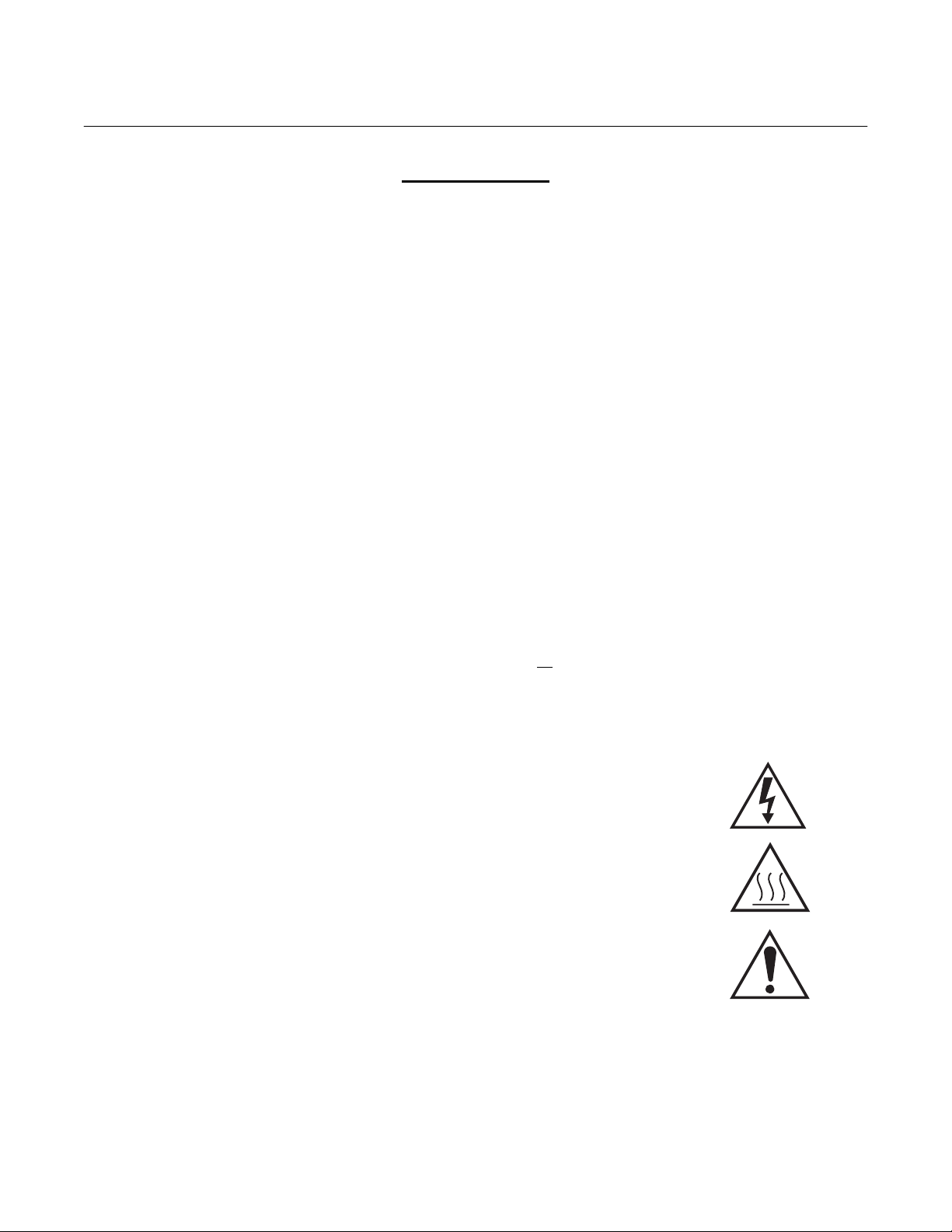
7. Where equipment or covers are marked with the symbol to the right, hazard-
ous voltages are likely to be present beneath. These covers should only be
removed when power is removed from the equipment — and then only by
trained service personnel.
8. Where equipment or covers are marked with the symbol to the right, there is a
danger from hot surfaces beneath. These covers should only be removed by
trained service personnel when power is removed from the equipment. Certain surfaces may remain hot to the touch.
9. Where equipment or covers are marked with the symbol to the right, refer to
the Operator Manual for instructions.
10. All graphical symbols used in this product are from one or more of the follow-
ing standards: EN61010-1, IEC417, and ISO3864.
P-2 Rosemount Analytical Inc. A Division of Emerson Process Management
Instruction Manual
1
IB-106-340AC Rev. 1.1
SPS 4000
SECTION 1
DESCRIPTION AND SPECIFICATIONS
NOTE
The SPS 4000 Single Probe Autocalibration Sequencer operates exactly the same with either
the Oxymitter 4000 Oxygen Transmitter or the Oxymitter 5000 Oxygen Transmitter with
OUNDATION
F
instruction bulletin also include the Oxymitter 5000. When referred to an instruction bulletin
for more information, reference IB-106-340 for the Oxymitter 4000 and IB-106-340-FB for the
Oxymitter 5000.
fieldbus Communications. Any references to the Oxymitter 4000 throughout this
April 2001
1-1 COMPONENT CHECKLIST
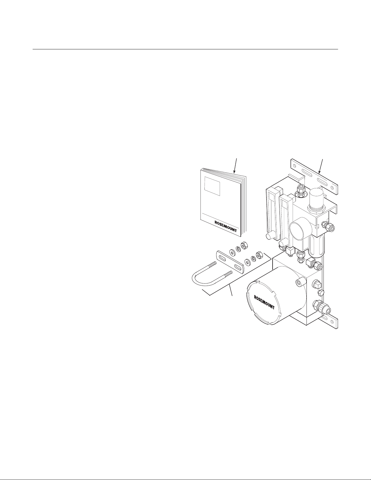
A typical SPS 4000 Single Probe Autocalibration Sequencer should contain the items shown
in Figure 1-1. Record the part number, serial
number, and order number for the SPS 4000 on
the first page of this manual.
Also, use the product matrix in Table 1-1 to
compare your order number against your unit.
The first part of the matrix defines the model.
The last part defines the various options and
features of the sequencer. Ensure the features
and options specified by your order number are
on or included with the unit.
1-2 OVERVIEW
The SPS 4000 provides the capability of performing automatic, timed or on demand, calibrations of a single Oxymitter 4000 without sending
a technician to the probe site.
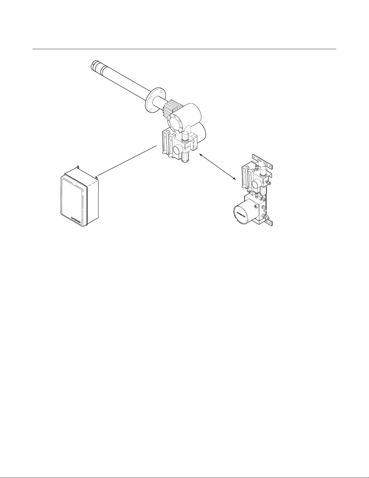
The SPS 4000 can be mounted either directly to
an In situ Oxymitter 4000 or at a remote location
if space is limited. See Figure 1-2. However, this
instruction bulletin only covers remote mounted
sequencers. For information regarding integrally
mounted sequencers, refer to the Oxymitter
4000 Oxygen Transmitter Instruction Bulletin.
For information on equipping your existing
Oxymitter 4000 with an integrally mounted SPS
4000, contact Rosemount.
1
3
1. Instruction Bulletin
2. SPS 4000 (shown with optional reference air components)
3. Optional Mounting Hardware (for pipe mounting)
Figure 1-1. Typical SPS 4000 Package
2
26010001
Rosemount Analytical Inc. A Division of Emerson Process Management Description and Specifications 1-1

Instruction Manual
IB-106-340AC Rev. 1.1
April 2001
Table 1-1. Product Matrix
SPS 4000 B Autocalibration System for Oxymitter 4000 or Oxymitter 5000. Mounted separate from the probe.
SPS 4000 Autocalibration System - Instruction Bulletin
Code Oxygen Analyzer System
20 Used with Oxymitter 4000 or Oxymitter 5000 system (remote mounted only)
SPS 4000
Code Reference Air
1 No reference air required
2 Reference air provided
Code Fittings and Tubing
1 Brass Fittings, Teflon Tubing
2 Stainless Steel Fittings and Tubing
Code Electrical Classification
10 NEMA 4X
20 Hazardous Area Classifications - Cenelec EExd IIB + H2
30 Hazardous Area Classifications (Class I, Div. I, Group B,C,D) - PENDING
SPS 4000 B 20 1 1 10 Example
Notes:
(1)
Reference air is recommended with 9 ft (2.74 m) and 12 ft (3.66 m) long probes. Reference air is also recommended when ambient air may
not contain the normal 20.95% O
unit nearby with leaks.
2)
Customer to pipe from remote SPS 4000 to probe.
3)
Hazardous area classifications require stainless steel fittings and tubing.
, such as when the probe is mounted into a positive pressure duct with leaks or where there is a process
2
(1)
(2)
(3)
(3)
Table 1-2. Calibration Components
Part Number Description
1A99119G01 Two disposable calibration gas bottles—0.4% and 8%
O
, balance nitrogen—550 liters each, includes bottle
2
rack*
1A99119G02 Two flow regulators for calibration gas bottles
*Calibration gas bottles cannot be shipped via airfreight.
When the bottles are used with “CALIBRATION RECOMMENDED” features,
the bottles should provide 2 to 3 years of calibrations in normal service.
1-2 Description and Specifications Rosemount Analytical Inc. A Division of Emerson Process Management
SPS 4000
1
Instruction Manual
IB-106-340AC Rev. 1.1
April 2001
OXYMITTER 4000
INTEGRAL OR
REMOTE
INTEGRALLY
MOUNTED SPS 4000
SINGLE PROBE
AUTOCALIBRATION
SEQUENCER
(1 PROBE)
REFER TO IB-106-340
INTELLIGENT MULTIPROBE
IMPS 4000
TEST GAS SEQUENCER
FOR USE WITH OXYMITTER 4000
(1 TO 4 PROBES)
Figure 1-2. Autocalibration System Installation Options
In addition to the SPS 4000, multiprobe sequencers are also available as shown in Figure
1-2. Rosemount has offered multiprobe autocalibration sequencer systems for many years.
These autocalibration systems are most cost
REMOTE MOUNTED SPS 4000
SINGLE PROBE
AUTOCALIBRATION SEQUENCER
FOR USE WITH OXYMITTER 4000
(EXPLO VERSIONS MUST BE REMOTE MOUNTED)
(1 PROBE)
26010003
effective for boilers and other combustion processes that utilize many probes. Users with only
one probe per combustion process can now
take advantage of Rosemount’s autocalibration
capability by utilizing the SPS 4000.
Rosemount Analytical Inc. A Division of Emerson Process Management Description and Specifications 1-3

Instruction Manual
IB-106-340AC Rev. 1.1
April 2001
1-3 SPECIFICATIONS
Mounting ............................................................. Integral to Oxymitter 4000
Remote from Oxymitter 4000
Materials of Construction
Manifold/electronics enclosure ................. Aluminum
Mounting brackets .................................... 316 stainless steel (SS)
Pneumatic fittings ..................................... 1/8 in. brass NPT (SS optional)
Pneumatic tubing ...................................... 1/4 in. Teflon (SS optional)
Assembly hardware .................................. Galvanized and stainless steel
Humidity range .................................................... 100% relative humidity
Ambient temperature range ................................ -40° to 149°F (-40° to 65°C)
Electrical classification ........................................ NEMA 4X (IP56)
Explosion-proof option (both pending) ................ CENELEC EExd IIB + H2
(Class 1, Div. 1, Group B, C, D)
SPS 4000
Electrical feedthroughs........................................ 1/2 in. NPT
Input power.......................................................... 90 to 250VAC, 50/60Hz
Power consumption............................................. 5VA maximum
External electrical noise ...................................... EN 50 082-2, includes 4KV electrostatic discharge
Handshake signal to/from
Oxymitter 4000 (self-powered) ................. 5V (5mA maximum)
Cal initiate contact input from control room......... 5 to 30VDC, Form A (SPST)
(one “In-Cal”, one “Cal Failed”)
Cabling distance between SPS 4000 and
Oxymitter 4000 ......................................... Maximum 1000 ft (303 m)
Piping distance between SPS 4000 and
Oxymitter 4000 ......................................... Maximum 300 ft (91 m)
Approximate shipping weight .............................. 10 lbs (4.5 kg)
Fisher-Rosemount has satisfied all obligations coming from the European legislation to harmonize
the product requirements in Europe.
1-4 Description and Specifications Rosemount Analytical Inc. A Division of Emerson Process Management

SPS 4000
1
Instruction Manual
IB-106-340AC Rev. 1.1
April 2001
1-4 PHYSICAL DESCRIPTION
The main components of the SPS 4000 are described in the following paragraphs and illustrated in Figure 1-3.
a. Manifold
The manifold provides a mounting platform
for the circuit board(s) and terminations and
contains the electrical feedthroughs. Also,
calibration gases are piped into and sequenced through solenoids mounted on the
manifold.
b. Calibration Gas Solenoids
The calibration gas solenoids sequence the
calibration gases. One solenoid controls
calibration gas 1 (high calibration gas), and
the other controls calibration gas 2 (low
calibration gas). The solenoids activate and
deactivate to allow the calibration gases to
flow between the sequencer and Oxymitter
4000.
c. Pressure Switch
The pressure switch detects if the pressure
of a calibration gas is low, which can be
caused by an empty gas bottle, a disconnected gas line, etc. Calibration is prohibited when calibration gas pressure is low.
d. Power Supply Board
This board converts the incoming line voltage from AC to DC for use by the solenoids,
terminations, and the programmable logic
device. The power supply board also has a
5 A, 250 V, slow blow fuse.
REFERENCE AIR
PRESSURE REGULATOR
(OPTIONAL)
NOTE:
CALIBRATION GAS
FLOWMETER
MANIFOLD COVER IS
REMOVED TO SHOW
INTERNAL COMPONENTS.
ALSO, BOARD COMPONENTS
ARE NOT SHOWN FOR CLARITY.
PRESSURE
SWITCH
CALIBRATION GAS 1
(HIGH CAL GAS)
SOLENOID
INTERFACE
BOARD
Figure 1-3. SPS 4000 Components
REFERENCE AIR
FLOWMETER
(OPTIONAL)
MANIFOLD
CALIBRATION GAS 2
(LOW CAL GAS)
SOLENOID
POWER
SUPPLY BOARD
TERMINAL COVER
26010002
Rosemount Analytical Inc. A Division of Emerson Process Management Description and Specifications 1-5

Instruction Manual
IB-106-340AC Rev. 1.1
April 2001
SPS 4000
e. Interface Board
The interface board contains a programmable logic device (PLD) that has the electronics to energize and deenergize the
solenoids based on a signal from the Oxymitter 4000.
f. Calibration Gas Flowmeter
The calibration gas flowmeter indicates the
flow rate of calibration gas flowing to the
Oxymitter 4000.
g. Reference Air Flowmeter (Optional)
The reference air flowmeter indicates the
amount of reference air continuously flowing
to the Oxymitter 4000.
h. Pressure Regulator (Optional)
The pressure regulator ensures the instrument air (reference air) flowing to the Oxymitter 4000 is at a constant pressure [20 psi
(138 kPa)]. The regulator also has a filter to
remove particulates in the reference air and
a drain valve to bleed the moisture that collects in the filter bowl.
i. Terminal Strip
The terminal strip housed within the terminal cover provides convenient access for all
signal and power user connections.
describe how an Oxymitter 4000 is autocalibrated when used with the SPS 4000.
a. In addition to the calibration methods avail-
able via the Oxymitter 4000 keypad, HART
communicator, AMS software, or a remote
contact, the SPS 4000 works in conjunction
with the Oxymitter 4000’s CAL RECOMMENDED feature to perform an autocalibration. This feature automatically per-forms an
impedance check every hour on the Oxymitter 4000. If a calibration is recommended
and its contact output signal is set for
“handshaking” with the sequencer, the
Oxymitter 4000 sends a signal to the sequencer. The sequencer automatically performs a calibration upon receiving the
signal.
Thus, no human interface is required for the
automatic calibration to take place.
b. When a calibration is required, the Oxymit-
ter 4000 sends a signal to the programmable logic device (PLD) on the interface
board of the sequencer. The PLD energizes
the calibration gas 1 (high O2) solenoid.
Calibration gas 1 then flows through the sequencer to the Oxymitter 4000. The Oxymitter 4000 measures the oxygen content of
calibration gas 1 and sends a signal to the
sequencer indicating that it received the
gas. When the sequencer receives the signal, the PLD deenergizes the calibration
gas 1 solenoid.
1-5 THEORY OF OPERATION
The Oxymitter 4000 is one of the few instruments found in industry that permit the permanent piping of a calibration standard into the
probe. Most instruments measuring pressure,
flow, or temperature require that a calibration
standard be brought to the instrument or that
the instrument be taken to the calibration source
in the instrument shop.
The permanent calibration gas connections allow for auto-calibrations to occur without operator intervention. The following paragraphs
1-6 Description and Specifications Rosemount Analytical Inc. A Division of Emerson Process Management
c. Next, the PLD energizes the calibration gas
2 (low O2) solenoid, and calibration gas 2
then flows through the sequencer to the
Oxymitter 4000. The Oxymitter 4000 measures the oxygen content of calibration gas 2
and sends a signal to the sequencer indicating that it received the gas. After measuring the two calibration gases, the
Oxymitter 4000 automatically makes an internal calibration adjustment and sends the
signal to the sequencer. When the sequencer receives the signal, the PLD
deenergizes the calibration gas 2 solenoid.

SPS 4000
1
Instruction Manual
IB-106-340AC Rev. 1.1
April 2001
OXYMITTER 4000
LOGIC I/O
CALIBRATION GAS
CHECK VALVE
(SEE NOTE 1)
SPS 4000
OXYMITTER 4000 (BOTTOM VIEW)
CALIBRATION
GAS FITTING
REFERENCE AIR
(SEE NOTE 2)
INSTRUMENT
AIR IN
(SEE NOTE 2)
NOTE 1.
CALIBRATION
GAS 1
(HIGH O )
A CHECK VALVE IS REQUIRED AT THE
OXYMITTER 4000 (BETWEEN THE CALIBRATION GAS FITTING AND THE GAS LINE)
TO PREVENT THE MIGRATION OF PROCESS
GASES DOWN THE CALIBRATION GAS LINE.
CLEAN, DRY INSTRUMENT AIR IS
2.
RECOMMENDED FOR REFERENCE AIR.
NO REFERENCE AIR IS REQUIRED IF
AMBIENT AIR CONDITIONS CONTAIN
20.95% OXYGEN.
2
CALIBRATION
GAS 2
(LOW O )
2
26010004
Figure 1-4. SPS 4000 Calibration Setup
Rosemount Analytical Inc. A Division of Emerson Process Management Description and Specifications 1-7

Instruction Manual
IB-106-340AC Rev. 1.1
April 2001
SPS 4000
1-8 Description and Specifications Rosemount Analytical Inc. A Division of Emerson Process Management

SPS 4000
2
Instruction Manual
IB-106-340AC Rev. 1.1
April 2001
SECTION 2
INSTALLATION
2-1 OVERVIEW
This section describes the installation of the
SPS 4000.
Before starting to install this equipment, read the “Safety Instructions for
the Wiring and Installation of this Apparatus” at the front of this Instruction
Bulletin. Failure to follow the safety
instructions could result in injury or
death.
Install all protective equipment covers
and safety ground leads after installation. Failure to install covers and
ground leads could result in serious
injury or death.
2-2 MECHANICAL INSTALLATION
a. Reference Air (Figure 2-1)
1. For units with the optional reference air
components, connect the instrument
air supply to the IN port of the pressure
regulator.
2. The pressure regulator is factory set at
20 psi (138 kPa). If necessary, readjust
by turning the knob on the top of the
regulator until the desired pressure is
obtained.
3. Next, connect the reference air from
the upper 1/4 in. tube fitting on the reference air flowmeter to the REF GAS
port on the Oxymitter 4000.
b. Calibration Gas (Figure 2-1)
1. Connect O2 calibration gas 1 (high
calibration gas) to the HIGH CAL GAS
IN 1/4 in. tube fitting on the top of the
manifold. Ensure the calibration gas
pressure is set at 20 psi (138 kPa).
The outline drawing in Figure 2-1 shows
mounting centers and clearances of the SPS
4000. The unit is designed to mount on a wall,
bulkhead, or pipe. Ensure the unit is installed
according to the following specifications.
a. Install the unit no further than 300 ft (91 m)
from the Oxymitter 4000 and no further than
1000 ft (303 m) from the electronics package or any customer-supplied remote input
or relay output connections in the control
room.
b. Locate the unit where the ambient tem-
perature is between -40° and 149°F (-40°
and 65°C).
2-3 GAS CONNECTIONS
Use the following procedure to connect the calibration gases and reference air.
Rosemount Analytical Inc. A Division of Emerson Process Management Installation 2-1
Instrument air is not recommended for
the high calibration gas. Do not use
100% nitrogen as a low gas (zero gas).
It is suggested that the low (zero) gas
be between 0.4% and 2.0% O2. Do not
use gases with hydrocarbon concentrations of more than 40 parts per million. Failure to use proper gases will
result in erroneous readings.
2. Connect O2 calibration gas 2 (low calibration gas) to the LOW CAL GAS IN
1/4 in. tube fitting on the top of the
manifold. Ensure the calibration gas
pressure is set at 20 psi (138 kPa).
3. Connect the calibration gas from the
upper 1/4 in. tube fitting on the calibration gas flowmeter to the check valve
connected to the CAL GAS port on the
Oxymitter 4000.

Instruction Manual
IB-106-340AC Rev. 1.1
April 2001
1/4 IN. TUBE FITTING
FOR HIGH CALIBRATION
0.94 (23.88) 0.94 (23.88)
1/4 IN. TUBE FITTING FOR
LOW CALIBRATION GAS IN
GAS IN
1/4 IN. TUBE TO CALIBRATION
GAS FLOWMETER
SPS 4000
CALIBRATION GAS FLOWMETER
(CALIBRATION GAS OUT
TO OXYMITTER 4000)
1/2 IN. NPT CONDUIT PORTS
(SEE NOTE 2)
2.00
(50.80)
13.50
(342.90)
4.25
(107.95)
9.00 (228.60)
NOMINAL
14.81
(376.17)
NOMINAL
REFERENCE AIR
FLOWMETER (OPTIONAL)
(REFERENCE AIR OUT
TO OXYMITTER 4000)
1/2 IN. NPT
CONDUIT PORT
(SEE NOTE 2)
2.00 (50.80)
NOMINAL
CLEARANCE
TO REMOVE
COVER
NOTES: 1.
DIMENSIONS ARE IN INCHES WITH
MILLIMETERS IN PARENTHESES.
2.
THREE 1/2 IN. NPT PORTS ARE PROVIDED
FOR LOGIC I/O AND SIGNAL CONNECTIONS.
THE CABLE ROUTING WILL BE DETERMINED
BY THE CUSTOMER.
1/4 IN. TUBE FITTING
FOR INSTRUMENT
AIR IN (OPTIONAL)
1/2 IN. CONDUIT
FITTING FOR LINE
VOLTAGE
6.12 (155.45)
NOMINAL
26010006
Figure 2-1. Installation
2-2 Installation Rosemount Analytical Inc. A Division of Emerson Process Management

SPS 4000
2
Instruction Manual
IB-106-340AC Rev. 1.1
April 2001
2-4 ELECTRICAL CONNECTIONS
All wiring must conform to local and national
codes. Use the following procedure to connect
an SPS 4000 to an Oxymitter 4000.
Disconnect and lock out power before
connecting the unit to the power
supply.
NOTE
Ensure the Oxymitter 4000 is set up to
handshake with the sequencer by configuring the logic I/O to mode 8. Refer
to the Oxymitter 4000 Oxygen Transmitter Instruction Bulletin for more information.
a. Remove screws (20, Figure 4-1) securing
terminal cover (19) and remove the cover.
b. Route the line voltage leads into the mani-
fold through the lower 1/2 in. conduit fitting
on the right side of the manifold (Figure 2-1)
and out through the bottom of the manifold.
Connect the incoming 90 to 250 VAC, 50/60
Hz line voltage leads to the terminal strip as
indicated in Figure 2-2.
c. Route the handshake logic I/O wires
through one of the 1/2 in. NPT conduit ports
on the manifold (Figure 2-1) and out
through the bottom of the manifold. Connect
the 5V (5 mA maximum) logic I/O leads
from the Oxymitter 4000 to the terminal strip
as indicated in Figure 2-2.
d. To set up the SPS 4000 to initiate a calibra-
tion from a remote location, route the 5 VDC
calibration initiate contact input through one
of the 1/2 in. NPT conduit ports on the
manifold (Figure 2-1) and out through the
bottom of the manifold. Connect the input
leads to the terminal strip as shown in
Figure 2-2.
e. Relay output connections are available on
the unit to signal when the Oxymitter 4000
is in calibration or when calibration failed.
Relay outputs can be connected to either
indicator lights or a computer interface. The
relay contacts are capable of handling a 5
to 30 VDC maximum power source. The
cabling requirement is 1000 ft (303 m)
maximum. Route the relay output wires
through one of the 1/2 in. NPT conduit ports
on the manifold (Figure 2-1) and out
through the bottom of the manifold. Connect
the relay output wires to the terminal strip
as shown in Figure 2-2.
f. Once all connections are made, install ter-
minal cover (19, Figure 4-1) and secure with
screws (20).
Rosemount Analytical Inc. A Division of Emerson Process Management Installation 2-3

Instruction Manual
IB-106-340AC Rev. 1.1
April 2001
SPS 4000
5V(5mA
MAXIMUM)
LOGIC I/O
5 VDC (SELF-POWERED)
TO REMOTE CONTACT
INPUT CONNECTION
CAL INITIATE CAL FAIL
NOT USED
WHITE
NOT USED
BLACK
HANDSHAKE
CONNECTION
TO
OXYMITTER
4000
YELLOW
BROWN
5-30VDCTO
RELAY OUTPUT
CONNECTIONS
RED
BLUE
IN CAL
++++
ORANGE
GREEN
LINE IN
GROUND
NEUTRAL
----
90 - 250 VAC,
50/60 HZ LINE
VOLTAGE
INPUT
FACTORY WIRING TO INTERFACE BOARD
Figure 2-2. Electrical Connections
FACTORY WIRING TO
POWER SUPPLY BOARD
26010007
2-4 Installation Rosemount Analytical Inc. A Division of Emerson Process Management

SPS 4000
3
Instruction Manual
IB-106-340AC Rev. 1.1
April 2001
SECTION 3
OPERATION
3-1 OVERVIEW
This section specifies the requirements to set up
an Oxymitter 4000 calibration and how to verify
the calibration gas flow setup. It also explains
the differences between automatic and semiautomatic calibrations and how to initiate them.
3-2 CALIBRATION REQUIREMENTS
a. Two tanks of precision calibration gas mix-
tures are required. Recommended calibration gases are nominally 0.4% and 8.0%
oxygen in nitrogen.
Do not use 100% nitrogen as a low gas
(zero gas). It is suggested that gas for
the low (zero) be between 0.4% and
2.0% O2. Do not use gases with hydrocarbon concentrations of more
than 40 parts per million. Failure to
use proper gases will result in erroneous readings.
12054 S.W. Doty Avenue
Chicago, Illinois 60628
312/568-8840
603 Bergen Street
Harrison, New Jersey 07029
201/485-1995
255 Brimley Road
Scarborough, Ontario, Canada
416/266-3161
SCOTT ENVIRONMENTAL
TECHNOLOGY, INC.
SCOTT SPECIALTY GASES
2600 Cajon Blvd.
San Bernardino, California 92411
714/887-2571
TWX: 910-390-1159
1290 Combermere Street
Troy, Michigan 48084
314/589-2950
In addition to the optional disposable gas
bottles available from Rosemount, two additional sources of calibrated gas mixtures
are:
LIQUID CARBONIC GAS CORP.
SPECIALTY GAS LABORATORIES
700 South Alameda Street
Los Angeles, California 90058
213/585-2154
767 Industrial Road
San Carlos, California 94070
415/592-7303
9950 Chemical Road
Pasadena, Texas 77507
713/474-4141
Rosemount Analytical Inc. A Division of Emerson Process Management Operation 3-1
Route 611
Plumsteadville, Pennsylvania 18949
215/766-8861
TWX: 510-665-9344
2616 South Loop West
Suite 100
Houston, Texas 77054
713/669-0469
b. A check valve is required at the Oxymitter
4000 (between the calibration fitting and the
gas line) to prevent the migration of process
gases down the calibration gas line.
A typical calibration setup for the Oxymitter
4000 is shown in Figure 1-4.

Instruction Manual
IB-106-340AC Rev. 1.1
April 2001
SPS 4000
3-3 CALIBRATION GAS FLOW SETUP
After installing the SPS 4000 as described in
Section 2, calibrate the Oxymitter 4000 to verify
SPS 4000 operation and the communication link
between the sequencer and Oxymitter 4000.
a. Verify that both calibration gases are con-
nected to the SPS 4000. Also verify that the
pressure regulators on both calibration gas
bottles are set to 20 psig (138 kPa gage).
b. Initiate a semi-automatic calibration using
one of the methods specified in paragraph
3-5.
NOTE
Only set the calibration gas flowmeter
upon initial installation and after
changing the diffusion element in the
Oxymitter 4000. Refer to the flowmeter
adjustments in Section 4 for more information.
c. As the Oxymitter 4000 and SPS 4000 apply
the first calibration gas, set the calibration
gas flowmeter to 5 scfh. During the application of the second calibration gas, verify that
the flowmeter reads 5 scfh. If not, adjust the
pressure regulator on the second calibration
gas bottle so the 5 scfh flow is provided.
3-4 AUTOMATIC CALIBRATION
AMS. Refer to the logic I/O information in
the HART/AMS section of the Oxymitter
4000 Oxygen Transmitter Instruction Bulletin for more information.
b. Timed Interval
An automatic calibration can also be programmed to occur at a specific time interval,
in hours, using the HART communicator or
AMS software. Refer to the HART/AMS
section of the Oxymitter 4000 Oxygen
Transmitter Instruction Bulletin for this
procedure.
3-5 SEMI-AUTOMATIC CALIBRATION
Semi-automatic calibrations are operator initiated and can be performed using the Oxymitter
4000 keypad, HART handheld communicator/
AMS software, or a remote contact. In addition,
the calibration gases must be permanently
piped to the Oxymitter 4000.
a. Oxymitter 4000 Keypad
A semi-automatic calibration can be initiated
by pressing the CAL button on the Oxymitter 4000 keypad. For more information, refer to the Oxymitter 4000 Oxygen
Transmitter Instruction Bulletin.
b. HART Handheld Communicator/AMS
Software
Automatic calibrations require no operator action and can be performed through the Oxymitter 4000 CAL RECOMMENDED feature or
through scheduled time intervals that can be
programmed through the HART/AMS for the
Oxymitter 4000. In addition, the calibration
gases must be permanently piped to the Oxymitter 4000.
a. CAL RECOMMENDED
If the Oxymitter 4000 is configured for
handshake mode with the SPS 4000, the
Oxymitter 4000 can initiate a calibration by
sending a signal to the sequencer when the
CAL RECOMMENDED LED activates. To
enable handshake mode, the Oxymitter
4000 logic I/O must be set for mode 8.
Handshake mode is configured at the factory or can be accessed through HART/
3-2 Operation Rosemount Analytical Inc. A Division of Emerson Process Management
A semi-automatic calibration can be initiated
by connecting the HART handheld communicator, or AMS software, to the Oxymitter
4000 4-20 mA signal line and using the
HART communicator keypad or computer
keyboard to access the applicable calibration menu. Refer to the Oxymitter 4000
Oxygen Transmitter Instruction Bulletin or
the available HART documentation for more
information.
c. Remote Contact
A semi-automatic calibration can be initiated
using a remote contact such as a customer’s control system. The remote contact
processes the calibration command on a
PC and sends the signal to the Oxymitter
4000. For more information on remote-site
calibrations, refer to the documentation for
the system in use.

SPS 4000
4
Instruction Manual
IB-106-340AC Rev. 1.1
April 2001
SECTION 4
MAINTENANCE AND SERVICE
4-1 OVERVIEW
This section describes service and routine
maintenance of the SPS 4000. Replacement
parts referenced are available from Rosemount.
Refer to Section VI for part numbers and ordering information.
Install all protective equipment covers
and safety ground leads after equipment repair or service. Failure to install covers and ground leads could
result in serious injury or death.
4-2 FUSE REPLACEMENT
The SPS 4000 has a fuse on the power supply
board. Refer to Table 7-1 for replacement fuse
specifications. Perform the following procedure
to check or replace the fuse.
Disconnect and lock out power before
working on any electrical components.
4-3 BOARD REPLACEMENT
Perform the following procedure to replace
power supply board (23, Figure 4-1) or interface
board (31).
Disconnect and lock out power before
working on any electrical components.
a. Turn off power to the system.
b. Remove screw (22) securing manifold cover
lock (21) and remove the lock.
c. Remove manifold cover (28).
d. Remove two screws (32) attaching spacers
(35) to manifold (38).
e. Being careful not to disconnect the board
wiring, carefully lift power supply board (23)
and interface board (31) from manifold (38)
and set aside. Do not lose o-rings (36) from
the bottom of spacers (35).
f. For the board to be replaced, tag all leads
to simplify installation.
a. Turn off power to the system.
b. Remove screw (22, Figure 4-1) securing
manifold cover lock (21) and remove the
lock.
c. Remove manifold cover (28).
d. Remove fuseholder (26) by pushing in the
top and turning 1/4 turn counterclockwise.
Remove fuse (25).
e. After checking or replacing fuse (25), install
fuseholder (26) by pushing in the top and
turning 1/4 turn clockwise.
f. Install manifold cover (28) and secure with
manifold cover lock (21) and screw (22).
Rosemount Analytical Inc. A Division of Emerson Process Management Maintenance and Service 4-1
g. If replacing the power supply board, refer to
Figure 4-2. Remove the line voltage input
leads from connector J7. Also, unplug calibration gas 1 solenoid leads from connector
J5, calibration gas 2 solenoid leads from
connector J4, and pressure switch leads
from connector J2.
h. If replacing the interface board, refer to
Figure 4-2. Remove the CAL INITIATE
leads from connector J3, CAL FAIL and IN
CAL leads from connector J4, and logic I/O
handshake connection from connector J5.
i. Remove stop nuts (33, Figure 4-1), washers
(34), and screws (37) securing power supply board (23) and interface board (31) to
spacers (35).

Instruction Manual
IB-106-340AC Rev. 1.1
April 2001
SPS 4000
46
47
45
48
49
50
43
44
42
51
41
40
52
39
12
10
38
3
1
5
4
2
6
8
9
10
7
28
29
30
33
32
31
34
26
27
25
35
36
37
12
11
21
22
23
24
NOTE: A STANDARD SPS 4000 IS EQUIPPED WITH TEFLON
20
TUBING AND BRASS FITTINGS. OPTIONAL STAINLESS
STEEL TUBING AND FITTINGS ARE ALSO AVAILABLE.
REFER TO SECTION VI FOR ORDERING INFORMATION.
14
15
16
17
18
19
12
13
26010009
Figure 4-1. SPS 4000, Exploded View
4-2 Maintenance and Service Rosemount Analytical Inc. A Division of Emerson Process Management

SPS 4000
4
1. Reference Air Pressure
Regulator (Optional)
2. Straight Fitting
3. Mounting Bracket
4. Flat Washer
5. Lockwasher
6. Hex Nut
7. Screw
8. Tube
9. Straight Fitting
10. Elbow Fitting
11. Hex Head Plug
12. Square Head Plug
13. Conduit Fitting
14. Ground Nut
15. Terminal Base
16. Terminal Strip
17. Screw
LEGEND FOR FIGURE 4-1
18. Terminal Cover Gasket
19. Terminal Cover
20. Screw
21. Manifold Cover Lock
22. Screw
23. Power Supply Board
24. Calibration Gas 2 Solenoid
25. Fuse
26. Fuseholder
27. Pressure Switch
28. Manifold Cover
29. O-Ring
30. Calibration Gas 1 Solenoid
31. Interface Board
32. Screw
33. Stop Nut
34. Washer
35. Spacer
Instruction Manual
IB-106-340AC Rev. 1.1
April 2001
36. O-Ring
37. Screw
38. Manifold
39. Elbow Fitting (Optional)
40. Tubing (Optional)
41. Elbow Fitting (Optional)
42. Screw
43. Elbow Street Fitting (Optional)
44. Elbow Fitting
45. Reference Air Flowmeter
(Optional)
46. Calibration Gas Flowmeter
47. Elbow Fitting
48. Elbow Street Fitting (Optional)
49. Straight Fitting (Optional)
50. Flowmeter Bracket
51. Bracket
52. Screw
j. Carefully separate boards (23 and 31).
k. Connect replacement board to board (23 or
31).
l. Install screws (37), washers (34), and stop
nuts (33) to secure interface board (31) and
power supply board (23) to spacers (35).
m. Install all applicable leads in the appropriate
locations on the power supply board or interface board as shown in Figure 4-2.
n. Install power supply board (23, Figure 4-1)
and interface board (31) into manifold (38).
Align spacers (35) with the mounting holes
on the manifold and secure with screws
(32). Ensure o-rings (36) are installed between the spacers and the manifold
surface.
o. Install manifold cover (28) and secure with
manifold cover lock (21) and screw (22).
4-4 SOLENOID REPLACEMENT
Use this procedure to replace either calibration
gas 1 (high calibration gas) solenoid (30, Figure
4-1) or calibration gas 2 (low calibration gas)
solenoid (24).
Disconnect and lock out power before
working on any electrical components.
a. Turn off power to the system.
b. Shut off the calibration gases at the
cylinders.
c. Remove screw (22) securing manifold cover
lock (21) and remove the lock.
d. Remove manifold cover (28).
e. Remove two screws (32) attaching spacers
(35) to manifold (38).
Rosemount Analytical Inc. A Division of Emerson Process Management Maintenance and Service 4-3

Instruction Manual
IB-106-340AC Rev. 1.1
April 2001
TO PRESSURE
SWITCH
LINE IN
LINE
VOLTAGE
INPUT
NEUTRAL
GROUND
SPS 4000
POWER SUPPLY BOARD
TO CALIBRATION
GAS 1 SOLENOID
TO CALIBRATION
GAS 2 SOLENOID
GROUND
VAC INPUT TO OXYMITTER 4000
L1
N
INTERFACE BOARD
BLACK
WHITE
RED
BLUE
ORANGE
GREEN
YELLOWYELLOW
BROWN
+
CAL INITIATE
-
+
CAL FAIL
-
+
IN CAL
-
LOGIC I/O
+
HANDSHAKE TO
-
OXYMITTER 4000
REMOTE
CONTACT INPUT
STATUS
INDICATOR
OUTPUT
26010012
Figure 4-2. Board Connections
4-4 Maintenance and Service Rosemount Analytical Inc. A Division of Emerson Process Management

SPS 4000
4
Instruction Manual
IB-106-340AC Rev. 1.1
April 2001
f. Being careful not to disconnect the board
wiring, carefully lift the board and spacer
assembly from manifold (38) and set aside.
Do not lose o-rings (36) from the bottom of
spacers (35).
g. Tag and unplug solenoid (30 or 24) leads
from power supply board (23). Refer to
Figure 4-2. Calibration gas 1 solenoid wires
connect to connector J5, and calibration gas
2 solenoid wires connect to connector J4.
h. Remove the top nut of solenoid (30 or 24)
securing the coil assembly and washer to
the base. Remove the coil assembly, including the leads, and washer. Place a
13/16 in. deep socket over the solenoid
base and remove.
When installing a solenoid, do not
overtighten. Damage to the solenoid
may occur.
4-5 PRESSURE SWITCH REPLACEMENT
Use the following procedure to replace pressure
switch (27, Figure 4-1).
a. Turn off power to the system.
b. Shut off the calibration gases at the
cylinders.
c. Remove screw (22) securing manifold cover
lock (21) and remove the lock.
d. Remove manifold cover (28).
e. Remove two screws (32) attaching spacers
(35) to manifold (38).
f. Being careful not to disconnect the board
wiring, carefully lift the board and spacer
assembly from manifold (38) and set aside.
Do not lose o-rings (36) from the bottom of
spacers (35).
g. Tag and remove the leads from pressure
switch (27).
i. Install the new solenoid base. Be careful not
to overtighten. Install the new washer and
coil assembly and secure with the top nut.
Connect the leads to the proper connector
on power supply board (23). Refer to Figure
4-2 if necessary.
j. Carefully install the board and spacer as-
sembly into manifold (38, Figure 4-1) by
aligning spacers (35) with the mounting
holes on the manifold and securing with
screws (32). Ensure o-rings (36) are installed between the spacers and the manifold surface.
k. Install manifold cover (28), and secure with
manifold cover lock (21) and screw (22).
l. Turn on the calibration gases at the
cylinders.
h. Place a 1-1/16 in. 6-point socket over pres-
sure switch (27) and remove.
When installing the pressure switch,
do not overtighten. Damage to the solenoid may occur.
i. Install new pressure switch (27). Be careful
not to overtighten. Connect the leads to the
proper terminals on the pressure switch.
j. Carefully install the board and spacer as-
sembly into manifold (38, Figure 4-1) by
aligning spacers (35) with the mounting
holes on the manifold and securing with
screws (32). Ensure o-rings (36) are installed between the spacers and the manifold surface.
Rosemount Analytical Inc. A Division of Emerson Process Management Maintenance and Service 4-5

Instruction Manual
IB-106-340AC Rev. 1.1
April 2001
SPS 4000
k. Install manifold cover (28), and secure with
manifold cover lock (21) and screw (22).
l. Turn on the calibration gases at the
cylinders.
4-6 CHECK VALVE REPLACEMENT
The check valve may stick or become plugged
over time. Replace when necessary. If condensation deposits are noted upon removal, consider insulating the check valve.
4-7 PRESSURE REGULATOR (OPTIONAL)
MAINTENANCE
a. Pressure Adjustments
Reference air pressure regulator (1, Figure
4-1) is factory set to 20 psi (138 kPa). Adjust using the knob on top of the pressure
regulator if necessary.
In applications with a heavy dust loading,
the O
probe diffusion element may become
2
plugged over time, causing a slower speed
of response. The best way to detect a
plugged diffusion element is to note the time
it takes the Oxymitter 4000 to return to the
normal process reading after the last calibration gas is removed and the calibration
gas line is blocked off. A plugged element
also can be indicated by a slightly lower
reading on the flowmeter.
Change the diffusion element when the
calibration gas flowmeter reads slightly
lower during calibration or when the response time to the process flue gases becomes very slow. Each time the diffusion
element is changed, reset the calibration
gas flowmeter to 5 scfh and calibrate the
Oxymitter 4000. For more information on
changing the diffusion element, refer to the
instruction bulletin for the Oxymitter 4000 in
use.
b. Reference Air Flowmeter (Optional)
Do not use fingers to release valve
stem. The valve may release air at high
pressures and cause injury.
b. Condensation Drain
To drain excess moisture from the filter bowl
of reference air pressure regulator (1), use
a screwdriver or comparable tool to periodically release the valve stem on the bottom
of the pressure regulator.
4-8 FLOWMETER ADJUSTMENTS
a. Calibration Gas Flowmeter
Calibration gas flowmeter (46, Figure 4-1)
regulates the calibration gas flow and must
be set to 5 scfh. However, only adjust the
flowmeter to 5 scfh after placing a new diffusion element on the end of the Oxymitter
4000. Adjusting the flowmeter at any other
time can pressurize the cell and bias the
calibration.
Reference air flowmeter (45) regulates the
reference air and must be set to 2 scfh.
Adjust the flow with the knob on the bottom
of the reference air flowmeter when
necessary.
4-9 FLOWMETER REPLACEMENT
Use this procedure to replace either reference
air flowmeter (45, Figure 4-1) or calibration gas
flowmeter (46).
a. Turn off power to the system.
b. Shut off the calibration gases at the
cylinders.
c. Loosen, but do not remove, four screws
(42) securing flowmeter bracket (50) to
mounting bracket (3).
d. Flex the bottom of flowmeter bracket (50)
downward and away to disengage and remove the flowmeter bracket from mounting
bracket (3).
4-6 Maintenance and Service Rosemount Analytical Inc. A Division of Emerson Process Management

SPS 4000
4
Instruction Manual
IB-106-340AC Rev. 1.1
April 2001
e. For reference air flowmeter (45), remove
pressure regulator (1) by disconnecting
tubing (40) from elbow fitting (39). Also, disconnect the tubing between the Oxymitter
4000 and sequencer from straight
fitting (49).
For calibration gas flowmeter (46), disconnect the tubing between the Oxymitter 4000
and the sequencer at elbow fitting (47).
Also, disconnect tube (8) from elbow
fitting (44).
f. Remove screws (52) and bracket (51) se-
curing flowmeter (45 or 46) to flowmeter
bracket (50).
g. Remove flowmeter (45 or 46), with installed
fittings, from flowmeter bracket (50).
h. For reference air flowmeter (45), remove el-
bow street fittings (43 and 48). It is not necessary to remove fittings (39 and 49) from
the street fittings.
For calibration gas flowmeter (46), remove
elbow fittings (44 and 47).
i. Apply pipe thread sealant to the threads of
top fitting (48 or 47) and bottom fitting (43 or
44) and install fittings into new flowmeter
(45 or 46).
j. Position flowmeter (45 or 46) into flowmeter
bracket (50) and secure with bracket (51)
and screw (52).
k. For reference air flowmeter (45), connect
tubing (40) to elbow fitting (39) and install
pressure regulator (1). Also, connect the
tubing between the Oxymitter 4000 and sequencer to straight fitting (49).
For calibration gas flowmeter (46), connect
tube (8) to elbow fitting (44) and connect the
gas tubing between the Oxymitter 4000 and
sequencer to elbow fitting (47).
l. Slide the top slots of flowmeter bracket (50)
onto screws (42). Flex the bottom of the
bracket downward and toward mounting
bracket (3) to engage the bottom bracket
slots and screws. Tighten screws.
m. Turn on the calibration gases at the
cylinders.
Rosemount Analytical Inc. A Division of Emerson Process Management Maintenance and Service 4-7

Instruction Manual
IB-106-340AC Rev. 1.1
April 2001
SPS 4000
4-8 Maintenance and Service Rosemount Analytical Inc. A Division of Emerson Process Management

SPS 4000
5
Instruction Manual
IB-106-340AC Rev. 1.1
April 2001
SECTION 5
TROUBLESHOOTING
5-1 OVERVIEW
This section describes the SPS 4000 troubleshooting procedures. Additional troubleshooting
information can be found in the Oxymitter 4000
Oxygen Transmitter Instruction Bulletin.
Install all protective equipment covers
and safety ground leads after troubleshooting. Failure to replace covers
and ground leads could result in serious injury or death.
5-2 SPS 4000 TROUBLESHOOTING
Use the CAL FAIL and IN CAL relay outputs to
identify possible SPS faults.
a. If a calibration was not successfully com-
pleted, the SPS 4000 sends a CAL FAIL
contact indication to the control room. To
determine if the SPS 4000 caused the failed
calibration, go to the Oxymitter 4000 site to
view the keypad. Or, access the HART/AMS
menus. For more information on HART/
AMS, refer to the HART/AMS section in the
Oxymitter 4000 Oxygen Transmitter Instruction Bulletin.
1. If no alarms are indicated on the keypad or in the HART/AMS STATUS submenu, the calibration did not fail because of an Oxymitter 4000 fault.
Therefore, a calibration gas flow problem occurred. Refer to Table 5-1 or
Figure 5-1 to troubleshoot the SPS
4000.
2. If the LAST CAL FAILED alarm is indicated on the keypad or in the HART/
AMS STATUS sub-menu, the failure is
due to either a bad Oxymitter 4000 cell
or a calibration gas flow problem.
(a) Verify your calibration setup per
paragraph 2-3 in Section 2, INSTAL-LATION; Section 3, OPERATION; and paragraph 4-8 in
Section 4, MAINTENANCE AND
SERVICE.
(b) Perform another calibration and
monitor the process. If the calibration fails before both calibration
gases finish sequencing, a gas
flow problem exists. Refer to Table
5-1 or Figure 5-1 to troubleshoot
the SPS 4000.
If the calibration setup is correct
and the Oxymitter 4000 indicates
an invalid slope fault (fault 12) before the gases are purged and a
last calibration failed fault (fault 14)
after the gases are purged, replace
the Oxymitter 4000 cell per the
Oxymitter 4000 Oxygen Transmitter Instruction Bulletin.
b. If a semi-automatic or manual calibration is
being performed but no 5 - 30 VDC relay
output contact (IN CAL or CAL FAIL) is being received by the control room, the interface board relays are malfunctioning.
Replace the interface board per paragraph
4-3 in Section 4, MAINTENANCE AND
SERVICE.
NOTE
If the unit is performing frequent autocalibrations, investigate at the Oxymitter 4000 site or using HART/AMS. This
condition may indicate an aging cell in
the Oxymitter 4000.
Rosemount Analytical Inc. A Division of Emerson Process Management Troubleshooting 5-1

Instruction Manual
IB-106-340AC Rev. 1.1
April 2001
Table 5-1. SPS 4000 Fault Finding
Symptom Check Fault Remedy
SPS 4000
No calibration gas
flow
Wiring Improper wire connections,
loose connections, or damaged wiring
Logic I/O Oxymitter 4000 logic I/O not
set for calibration handshaking with SPS 4000
Calibration gas lines between cylinders and manifold
Calibration gas flowmeter
knob
Calibration gas line between
manifold and calibration gas
flowmeter
Fuse on power supply board Blown fuse Replace fuse per paragraph
Interface board option Interface board not sending
Check valve Clogged check valve Replace check valve per
Clogged calibration gas line Replace clogged calibration
Flowmeter knob not turned
counterclockwise to allow
flow
Clogged calibration gas line Replace clogged calibration
signals
Properly connect wiring or
secure loose wiring connections; replace damaged wiring if necessary.
Set logic I/O to mode 8 via
HART/AMS.
gas line.
Turn calibration gas flowmeter knob counterclockwise to allow calibration
gas to flow.
gas line.
4-2.
Replace interface board per
paragraph 4-3.
paragraph 4-6.
Calibration gas line between
calibration gas flowmeter and
check valve
Calibration gas flowmeter Clogged flowmeter Replace flowmeter per para-
Power supply output Power supply failure Replace power supply board
Solenoid Solenoid failure Replace solenoid per para-
Pressure switch Pressure switch failure Replace pressure switch per
Clogged calibration gas line Replace calibration gas line.
graph 4-9.
per paragraph 4-3.
graph 4-4.
paragraph 4-5.
5-2 Troubleshooting Rosemount Analytical Inc. A Division of Emerson Process Management

SPS 4000
5
SYMPTOM — NO CALIBRATION GAS FLOW
CHECK ALL WIRING BETWEEN
OXYMITTER 4000 AND SPS 4000.
IS
WIRING
PROPERLY
CONNECTED
AND
SECURE?
YES
CHECK LOGIC I/O SETTING VIA
HART/AMS.
PROPERLY CONNECT WIRING OR
NO
SECURE LOOSE WIRING CONNECTIONS; REPLACE DAMAGED
WIRING.
Instruction Manual
IB-106-340AC Rev. 1.1
April 2001
IS
LOGIC I/O
SET FOR
MODE 8?
YES
DISCONNECT CAL GAS INPUT
LINES AT MANIFOLD.
IS THERE
FLOW?
YES
ENSURE CAL GAS FLOWMETER
KNOB IS TURNED COUNTERCLOCKWISE TO ALLOW FLOW.
DOES
CAL GAS
FLOWMETER
REGISTER
FLOW?
YES
CHECK FUSE F1 ON POWER
SUPPLY BOARD.
NO
NO
NO
SET LOGIC I/O TO MODE 8 VIA
HART/AMS.
REPLACED CLOGGED CAL GAS
LINE BETWEEN CAL GAS
CYLINDER AND MANIFOLD.
REPLACED CLOGGED CAL GAS
LINE BETWEEN MANIFOLD AND
CAL GAS FLOWMETER.
F1
J2
J5
J4
J3
LO GAS
HI GAS
NO GAS
CAL RET
IS
FUSE
BLOWN?
NO
CONTINUED
ON SHEET
2OF2
YES
REPLACE FUSE PER
PARAGRAPH 4-2.
POWER SUPPLY BOARD
35970001
Figure 5-1. SPS 4000 Troubleshooting Flowchart (Sheet 1 of 2)
Rosemount Analytical Inc. A Division of Emerson Process Management Troubleshooting 5-3

Instruction Manual
IB-106-340AC Rev. 1.1
April 2001
SYMPTOM — NO CALIBRATION GAS FLOW (CONTINUED)
SPS 4000
CONTINUED
FROM SHEET
1OF2
PLACE JUMPER BETWEEN CAL
RET TERMINAL AND EITHER HI
GAS OR LO GAS TERMINAL OF J3.
SEE NOTE 1.
IS THERE
FLOW?
NO
USE METER (SEE NOTE 2)
TO CHECK FOR SHORT
BETWEEN CAL RET AND NO GAS
TERMINALS OF J3.
IS THERE
A SHORT?
NO
DISCONNECT SOLENOID FROM
POWER SUPPLY BOARD AND USE
METER TO MEASURE ACROSS
TWO OUTER PINS OF BOARD
CONNECTOR. SEE NOTE 4.
CHECK BOTH SOLENOIDS.
IS THERE
+30VDC?
YES
DISCONNECT CAL GAS LINE
AT MANIFOLD OUTPUT PORT.
YES
YES
NO
INTERFACE BOARD IS
NOT SENDING SIGNAL.
REPLACE INTERFACE
BOARD PER PARAGRAPH
4-3.
DISCONNECT CAL GAS
LINE AT CHECK VALVE.
REPLACE POWER
SUPPLY BOARD PER
PARAGRAPH 4-3.
NOTE 1:
NOTE 2:
NOTE 3:
NOTE 4:
DISCONNECT CAL GAS LINE
AT TOP FITTING OF CAL GAS
FLOWMETER.
REPLACE FAULTY CAL GAS
FLOWMETER PER PARAGRAPH
4-9.
SECURELY TIGHTEN ALL J3 SCREW TERMINALS ON
POWER SUPPLY BOARD TO MAKE CONNECTIONS.
USE A SIMPSON MODEL 260 OR EQUIVALENT
MULTIMETER.
IF REPLACING THE CHECK VALVE DOES NOT
CORRECT THE PROBLEM, A CLOG COULD EXIST IN
THE RED SILICON GAS TUBE WITHIN THE PROBE.
IF CHECKING CAL GAS 1 SOLENOID CONNECTOR J5,
ENSURE CAL RET TERMINAL IS JUMPERED TO HI GAS
TERMINAL OF J3. IF CHECKING CAL GAS 2 SOLENOID
CONNECTOR J4, ENSURE CAL RET TERMINAL IS
JUMPERED TO LO GAS TERMINAL OF J3.
IS THERE
FLOW?
NO
IS THERE
FLOW?
NO
YES
YES
REPLACE CHECK VALVE
PER PARAGRAPH 4-6.
SEE NOTE 3.
REPLACE CLOGGED
CAL GAS LINE BETWEEN
CAL GAS FLOWMETER
AND CHECK VALVE.
NO
IS THERE
FLOW?
YES
REPLACE PRESSURE SWITCH
PER PARAGRAPH 4-5.
REPLACE SOLENOID
PER PARAGRAPH 4-4.
35970002
Figure 5-1. SPS 4000 Troubleshooting Flowchart (Sheet 2 of 2)
5-4 Troubleshooting Rosemount Analytical Inc. A Division of Emerson Process Management

SPS 4000
6
Instruction Manual
IB-106-340AC Rev. 1.1
April 2001
SECTION 6
RETURN OF MATERIAL
6-1 If factory repair of defective equipment is re-
quired, proceed as follows:
a. Secure a return authorization from a Rose-
mount Analytical Sales Office or Representative before returning the equipment.
Equipment must be returned with complete
identification in accordance with Rosemount
instructions or it will not be accepted.
In no event will Rosemount be responsible
for equipment returned without proper
authorization and identification.
b. Carefully pack the defective unit in a sturdy
box with sufficient shock absorbing material
to ensure no additional damage occurs
during shipping.
c. In a cover letter, describe completely:
1. The symptoms that determined the
equipment is faulty.
2. The environment in which the equipment was operating (housing, weather,
vibration, dust, etc.).
3. Site from where the equipment was
removed.
4. Whether warranty or nonwarranty
service is requested.
5. Complete shipping instructions for the
return of the equipment.
d. Enclose a cover letter and purchase order
and ship the defective equipment according
to instructions provided in a Rosemount
Return Authorization, prepaid, to:
Rosemount Analytical Inc.
RMR Department
1201 N. Main Street
Orrville, Ohio 44667
If warranty service is requested, the defective unit will be carefully inspected and
tested at the factory. If failure was due to
conditions listed in the standard Rosemount
warranty, the defective unit will be repaired
or replaced at Rosemount's option, and an
operating unit will be returned to the customer in accordance with shipping instructions furnished in the cover letter.
For equipment no longer under warranty,
the equipment will be repaired at the factory
and returned as directed by the purchase
order and shipping instructions.
Rosemount Analytical Inc. A Division of Emerson Process Management Return of Material 6-1

Instruction Manual
IB-106-340AC Rev. 1.1
April 2001
SPS 4000
6-2 Return of Material Rosemount Analytical Inc. A Division of Emerson Process Management

Instruction Manual
7
IB-106-340AC Rev. 1.1
SPS 4000
SECTION 7
REPLACEMENT PARTS
Table 7-1. SPS 4000 Replacement Parts
Figure and Index No. Part Number Description
Figure 1-4 6292A97H03 Check Valve
Figure 4-1, 29 1A99089H01 Cover O-ring
Figure 4-1, 46 771B635H01 Flowmeter Assembly, Calibration Gas
Figure 4-1, 45 771B635H02 Flowmeter Assembly, Reference Air (Optional)
Figure 4-1, 1 1A99094H01 Reference Air Pressure Regulator (Optional)
Figure 4-1, 25 1A97913H03 Fuse, 5A, 250V, 5 20 mm, Slow Blow
Figure 4-1, 31 4850B56G01 Interface Board
Figure 4-1, 23 4850B54G01 Power Supply Board
Figure 4-1, 27 7305A67H01 Pressure Switch
Figure 4-1, 24 and 30 3D39435G01 Solenoid
Figure 4-1, 18 4850B75H01 Terminal Cover Gasket
Figure 4-1, 16 1A99147H01 Terminal Strip
April 2001
Table 7-2. Calibration Replacement Parts
Figure and Index No. Part Number Description
Figure 1-4 1A99119G01 Calibration Gas Bottles — 0.4% and 8% O2, balance nitrogen
— 550 liters each, includes bottle rack*
Figure 1-4 1A99119G02 Two flow regulators (for calibration gas bottles)
*Calibration gas bottles cannot be shipped via airfreight.
Rosemount Analytical Inc. A Division of Emerson Process Management Replacement Parts 7-1

Instruction Manual
IB-106-340AC Rev. 1.1
April 2001
SPS 4000
7-2 Replacement Parts Rosemount Analytical Inc. A Division of Emerson Process Management

SPS 4000
I
This index is an alphabetized listing of parts, terms, and procedures having to do with the Hazardous Area Oxygen/Combustibles Transmitter. Every item listed in this index refers to a location
in the manual by one or more page numbers.
Instruction Manual
IB-106-340AC Rev. 1.1
April 2001
SECTION 8
INDEX
A
Ambient Temperature Range, 1-4, 2-1
AMS, 1-6, 3-2, 5-1, 5-2, 5-3
Autocalibration, 1-1, 1-2, 1-3, 1-6
Automatic Calibration, 3-2
C
Calibration Gas, 1-5, 1-6, 2-1, 3-1, 3-2, 4-1, 4-6, 4-7,
5-2, 5-3
Calibration Gas Bottles, 1-2, 7-1
Check Valve, 2-1, 3-1, 4-6, 5-2, 5-4
Condensation Drain, 4-6
Contact Input, 1-4, 2-3
D
Drain Valve, 1-6
E
Electrical Classification, 1-2, 1-4
Electrical Connections, 2-3, 2-4
Electrical Feedthroughs, 1-4, 1-5
Electrical Noise, 1-4
Explosion-proof Rating, 1-4
F
Flow Regulators, 1-2, 7-1
Flowmeter, 1-6, 2-1, 3-2, 4-3, 4-6, 4-7, 5-2, 5-3, 5-4
Fuse, 4-1, 5-2, 5-3
G
Gas Connections, 2-1
H
Handshake Signal, 1-4, 2-3, 3-2
HART, 1-6, 3-2, 5-1, 5-2, 5-3
Humidity, 1-4
I
Input Power, 1-4
Interface Board, 1-6, 2-4, 4-1, 4-3, 4-4, 5-1, 5-2, 5-4
L
Line Voltage, 2-3
Logic I/O, 2-3, 2-4, 3-2, 5-2, 5-3
M
Manifold, 1-4, 1-5, 2-1
Mechanical Installation, 2-1
Mounting, 1-4, 2-1
Multiprobe Sequencers, 1-3
P
Piping Distance, 1-4
PLD, 1-6
Power Consumption, 1-4
Power Supply Board, 1-5, 4-1, 4-3, 4-4, 5-2, 5-3, 5-4
Pressure Regulator, 1-6, 2-1, 3-2, 4-3, 4-6, 4-7
Pressure Switch, 1-5, 4-3, 4-5, 5-2, 5-4
Product Matrix, 1-1, 1-2
R
Reference Air, 1-1, 1-2, 1-6, 2-1, 4-3, 4-6, 4-7
Relay Output, 2-1, 2-3
Remote Contact, 1-6, 3-2
Replacement Parts, 7-1
Return of Material, 6-1
S
Semi-automatic Calibration, 3-1, 3-2
Solenoid, 1-5, 1-6, 4-3, 4-5, 5-2, 5-4
Specifications, 1-4
T
Terminal Strip, 1-6
Troubleshooting, 5-1, 5-2, 5-3, 5-4
W
Weight, 1-4
Rosemount Analytical Inc. A Division of Emerson Process Management Index 8-1

Instruction Manual
IB-106-340AC Rev. 1.1
April 2001
SPS 4000
8-2 Index Rosemount Analytical Inc. A Division of Emerson Process Management

WARRANTY
Goods and part(s) (excluding consumables) manufactured by Seller are warranted to be free from
defects in workmanship and material under normal use and service for a period of twelve (12)
months from the date of shipment by Seller. Consumables, glass electrodes, membranes, liquid
junctions, electrolyte, o-rings, etc., are warranted to be free from defects in workmanship and
material under normal use and service for a period of ninety (90) days from date of shipment by
Seller. Goods, part(s) and consumables proven by Seller to be defective in workmanship and/or
material shall be replaced or repaired, free of charge, F.O.B. Seller's factory provided that the
goods, part(s) or consumables are returned to Seller's designated factory, transportation charges
prepaid, within the twelve (12) month period of warranty in the case of goods and part(s), and in
the case of consumables, within the ninety (90) day period of warranty. This warranty shall be in
effect for replacement or repaired goods, part(s) and the remaining portion of the ninety (90) day
warranty in the case of consumables. A defect in goods, part(s) and consumables of the commercial unit shall not operate to condemn such commercial unit when such goods, part(s) and
consumables are capable of being renewed, repaired or replaced.
The Seller shall not be liable to the Buyer, or to any other person, for the loss or damage directly
or indirectly, arising from the use of the equipment or goods, from breach of any warranty, or from
any other cause. All other warranties, expressed or implied are hereby excluded.
IN CONSIDERATION OF THE HEREIN STATED PURCHASE PRICE OF THE GOODS,
SELLER GRANTS ONLY THE ABOVE STATED EXPRESS WARRANTY. NO OTHER WARRANTIES ARE GRANTED INCLUDING, BUT NOT LIMITED TO, EXPRESS AND IMPLIED
WARRANTIES OR MERCHANTABILITY AND FITNESS FOR A PARTICULAR PURPOSE.
Limitations of Remedy. SELLER SHALL NOT BE LIABLE FOR DAMAGES CAUSED BY DELAY IN PERFORMANCE. THE SOLE AND EXCLUSIVE REMEDY FOR BREACH OF WARRANTY SHALL BE LIMITED TO REPAIR OR REPLACEMENT UNDER THE STANDARD
WARRANTY CLAUSE. IN NO CASE, REGARDLESS OF THE FORM OF THE CAUSE OF ACTION, SHALL SELLER'S LIABILITY EXCEED THE PRICE TO BUYER OF THE SPECIFIC
GOODS MANUFACTURED BY SELLER GIVING RISE TO THE CAUSE OF ACTION. BUYER
AGREES THAT IN NO EVENT SHALL SELLER'S LIABILITY EXTEND TO INCLUDE INCIDENTAL OR CONSEQUENTIAL DAMAGES. CONSEQUENTIAL DAMAGES SHALL INCLUDE, BUT
ARE NOT LIMITED TO, LOSS OF ANTICIPATED PROFITS, LOSS OF USE, LOSS OF REVENUE, COST OF CAPITAL AND DAMAGE OR LOSS OF OTHER PROPERTY OR EQUIPMENT.
IN NO EVENT SHALL SELLER BE OBLIGATED TO INDEMNIFY BUYER IN ANY MANNER
NOR SHALL SELLER BE LIABLE FOR PROPERTY DAMAGE AND/OR THIRD PARTY CLAIMS
COVERED BY UMBRELLA INSURANCE AND/OR INDEMNITY COVERAGE PROVIDED TO
BUYER, ITS ASSIGNS, AND EACH SUCCESSOR INTEREST TO THE GOODS PROVIDED
HEREUNDER.
Force Majeure. Seller shall not be liable for failure to perform due to labor strikes or acts beyond
Seller's direct control.
3491
3536/4-01

Instruction Manual
IB-106-340AC Rev. 1.1
April 2001
SPS 4000
SPS 4000
Emerson Process Management
Rosemount Analytical Inc.
Process Analytic Division
1201 N. Main St.
Orrville, OH 44667-0901
T (330) 682-9010
F (330) 684-4434
E gas.csc@emersonprocess.com
Pa rt n o. ____________
Se ria l no . ____________
Or d er no. ____________
Fisher-Rosemount GmbH & Co.
Industriestrasse 1
63594 Hasselroth
Germany
T 49-6055-884 0
F 49-6055-884209
ASIA - PACIFIC
Fisher-Rosemount
Singapore Private Ltd.
1 Pandan Crescent
Singapore 128461
Republic of Singapore
T 65-777-8211
F 65-777-0947
http://www.processanalytic.com
© Rosemount Analytical Inc. 2001
EUROPE, MIDDLE EAST, AFRICA
Fisher-Rosemount Ltd.
Heath Place
Bognor Regis
West Sussex PO22 9SH
England
T 44-1243-863121
F 44-1243-845354
LATIN AMERICA
Fisher - Rosemount
Av. das Americas
3333 sala 1004
Rio de Janeiro, RJ
Brazil 22631-003
T 55-21-2431-1882
 Loading...