

Safety Manual
308020EN, Edition 1
June 2007
Rosemount TankRadar Rex
Safety Manual For Use In Safety Instrumented Systems
www.rosemount-tg.com


Safety Manual
308020EN, Edition 1
June 2007
Rosemount TankRadar Rex
Safety Manual
Rosemount TankRadar Rex
First edition
www.rosemount-tg.com
Copyright
© June 2007
Rosemount Tank Radar AB

Rosemount TankRadar Rex
Copyright © June 2007
Rosemount Tank Radar AB
Spare Parts
Any substitution of non-recognized spare parts may jeopardize
safety. Repair, e.g. substitution of components etc, may also
jeopardize safety and is under no circumstances allowed.
Rosemount Tank Radar AB will not take any responsibility for
faults, accidents, etc caused by non-recognized spare parts or
any repair which is not made by Rosemount Tank Radar AB.
Safety Manual
308020EN, Edition 1
June 2007
WARNING
Do not open the Integrated Junction Box JBi
when the circuit is alive.
www.rosemount-tg.com

Safety Manual
308020EN, Edition 1
June 2007
Rosemount TankRadar Rex
Contents
Content s
1. SCOPE AND PURPOSE OF THE SAFETY MANUAL . . . . . . . . . . 1
2. R
3. S
EFERENCE DOCUMENTS. . . . . . . . . . . . . . . . . . . . . . . . . . . 2
COPE OF THE PRODUCT . . . . . . . . . . . . . . . . . . . . . . . . . . . 3
3.1 PURPOSE OF THE PRODUCT . . . . . . . . . . . . . . . . . . . . . . . . . . . . . . . . . 3
3.2 ASSUMPTIONS AND RESTRICTIONS . . . . . . . . . . . . . . . . . . . . . . . . . . . 3
3.3 FUNCTIONAL SPECIFICATION OF THE SAFETY FUNCTIONS . . . . . . . 3
3.4 PARAMETERS RELATED TO SAFETY FUNCTIONS . . . . . . . . . . . . . . . . 7
3.5 HARDWARE AND SOFTWARE CONFIGURATION . . . . . . . . . . . . . . . . . 12
4. INSTALLATION AND CONFIGURATION. . . . . . . . . . . . . . . . . . 13
4.1 CONFIGURATION WITH ONE RELAY . . . . . . . . . . . . . . . . . . . . . . . . . . . 14
4.2 CONFIGURATION WHEN USING TWO RELAYS IN SERIES . . . . . . . . . 17
4.3 VERIFICATION OF THE SAFETY FUNCTION . . . . . . . . . . . . . . . . . . . . . 20
4.4 WRITE PROTECTION . . . . . . . . . . . . . . . . . . . . . . . . . . . . . . . . . . . . . . . . 20
5. PROOF TESTS . . . . . . . . . . . . . . . . . . . . . . . . . . . . . . . . . . 22
5.1 TRIGGERING THE RELAY . . . . . . . . . . . . . . . . . . . . . . . . . . . . . . . . . . . . 22
5.2 HAND DIPPING . . . . . . . . . . . . . . . . . . . . . . . . . . . . . . . . . . . . . . . . . . . . . 23
5.3 VERIFICATION OF THE RELAY FUNCTION . . . . . . . . . . . . . . . . . . . . . . 23
5.4 REPAIR . . . . . . . . . . . . . . . . . . . . . . . . . . . . . . . . . . . . . . . . . . . . . . . . . . . 25
6. TERMS AND DEFINITIONS . . . . . . . . . . . . . . . . . . . . . . . . . . 26
Appendix FMEDA and Proven-in-use Assessment . . . . . . .27
i

Rosemount TankRadar Rex
Contents
Safety Manual
308020EN, Edition 1
June 2007
ii

Safety Manual
308020EN, Edition 1
June 2007
Rosemount TankRadar Rex
Chapter 1 Scope and Purpose of the
Safety Manual
1. Scope and Purpose of the Safety Manual
The purpose of the safety manual is to document all the
information, relating to TankRadar Rex 3900 Series, which is
required to enable the integration of TankRadar Rex into a safetyrelated system, in compliance with the requirements of IEC
61508.
1

Rosemount TankRadar Rex
Chapter 2 Reference Documents
2. Reference Documents
• IEC 61508
• IEC 61511
• Rosemount TankRadar Rex Installation Manual,
Ref. no. 308014EN
• Rosemount TankRadar Rex Service Manual,
Ref. no. 308012EN
• Rosemount TankRadar Rex Special Safety Instruction,
Ref. no. 308016E
• TankMaster WinSetup User’s Guide, Ref. no. 303027EN
• Rosemount TankRadar REX Technical Description,
Ref. no. 703010EN.
Safety Manual
308020EN, Edition 1
June 2007
2

Safety Manual
308020EN, Edition 1
June 2007
3. Scope of the Product
3.1 Purpose of the Product
The Rosemount TankRadar Rex 3900 Series is designed for high
performance level gauging in various types of storage tanks.
Temperature sensors, remote display unit, water level sensors,
pressure sensors, and other devices can be connected. Two
relays are available for alarm indication and overfill and dry run
protection.
3.2 Assumptions and Restrictions
Install the TankRadar Rex according to the instructions in this
document. The Rosemount TankRadar Rex Installation Manual
and the Rosemount TankRadar Rex Special Safety Instruction
provide further instructions for a safe installation.
Rosemount TankRadar Rex
Chapter 3 Scope of the Product
Note that the TankRadar Rex is not safety-rated during
maintenance work, configuration changes, or other activity that
affects the Safety Function. Alternative means should be used to
ensure process safety during such activities.
False echoes within the radar beam from flat obstructions with a
sharp edge may lead to a situation where the TankRadar Rex can
no longer be used for safety related functions with the listed failure
rates, Safe Failure Fraction and PFD
. However, reduced proof
AVG
test intervals can help to detect such unwanted causes.
Operating conditions are available in the TankRadar Rex
Technical Description, ref no. 703010EN.
3.3 Functional Specification of the Safety Functions
The Safety Function is based on the relay output (one or two
relays) used as the primary safety variable for overfill and dry run
protection. The relay function is configured to activate the alarm
mode at a preset product Level or product Ullage (Ullage is the
space between the top of the tank and the product surface).
3
Rosemount TankRadar Rex
Chapter 3 Scope of the Product
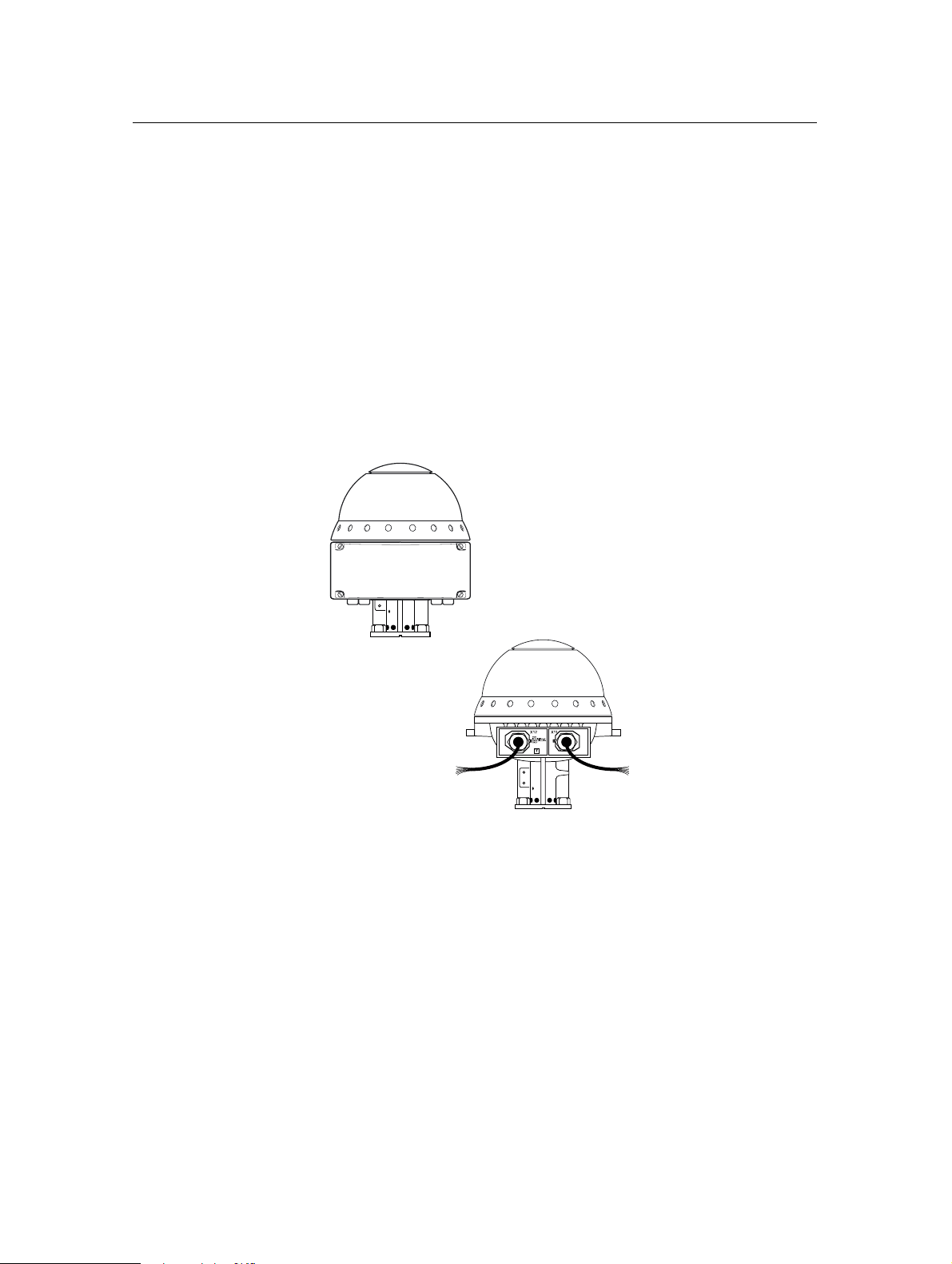
TankRadar Rex is equipped with two cable outputs for intrinsically
safe and non-intrinsically safe connections, respectively. Wires
are clearly marked with numbers and designation of wires is
shown on a printed plate at the cable outputs. The transmitter can
also be equipped with an Integrated Junction Box (JBi).
W1 1 is for the relays, the TRL/2 Bus, and the non-intrinsically safe
power supply.
W12 is for the intrinsically safe connection of Data Acquisition Unit
(DAU), Remote Display Unit RDU40, analog inputs, and
temperature sensors.
Safety Manual
308020EN, Edition 1
June 2007
Integrated Junction Box (JBi)
W12 Intrinsically
safe connections
W11 Non-Intrinsically
safe connections
Figure 1. Electrical connections on the TankRadar REX.
Connect to the relay ports on the W11 side, or to the X11 terminal
if the TankRadar REX with Integrated Junction Box JBi is used:
4

Safety Manual
308020EN, Edition 1
June 2007
Rosemount TankRadar Rex
Chapter 3 Scope of the Product
K1A
K1B
K2A
K2B
relay K1relay K1relay K1
relay K2
Figure 2. Connecting to the relay ports via Integrated Junction
Box (JBi).
Note! Depending on system configuration one or two relays are available.
3.3.1 Safety Function Using One Relay
The Safety Function is based on the relay output (relay K1 or relay
K2) used as the primary safety variable for overfill and dry run
protection. The Safety Function requires that the relay output is
configured as Normally Open. Normally Open refers to the
contact position when the relay is de-energized. This is also
referred to as the Alarm state. The terminology for Normally Open
can be summarized as described in Table 1 below:
Normally Open
Open Closed
De-energized Energized
Not active Active
Alarm (reset) Normal
Table 1. Relay terminology for relays configured as Normally
Open.
See the TankRadar REX Installation Manual for information on
how to configure the Relay Output Card (ROC) for operation in
Normally Open mode.
5

Rosemount TankRadar Rex
Chapter 3 Scope of the Product
3.3.2 Safety Function Using Two Relays in Series
This Safety Function is based on the two relay outputs coupled in
series used as the primary safety variable for overfill and dry run
protection. The Safety Function requires that the two relay outputs
are configured as follows: one relay Normally Open and the other
relay Normally Closed.
The default setting is Normally Open for both relays K1 and K2.
See the TankRadar REX Installation Manual for information on
how to configure the Relay Output Card (ROC) for operation in
Normally Open or Normally Closed mode.
The relays are configured in such manner that when the set point
(e.g. overfill) is reached one of the relays will "pull" while the
second relay will "release". Below the set point (normal operation)
the relays will be in the positions as shown in Figure 3:
Safety Manual
308020EN, Edition 1
June 2007
A
Relay K1
Relay K2
Figure 3. A. Relay positions under normal operation.
B. Wiring diagram for Safety Function using two relays coupled in series.
B
The system state is given by the states of the two relays according
to Table 2:
System state
Normal Energized De-energized
Alarm De-energized Energized
Relay K1
(Normally Open)
Relay K2
(Normally Closed)
Alarm Energized Energized
Alarm De-energized De-energized
Table 2. System state versus relay state with Safety Function using
two relays coupled in series.
6
 Loading...