

Rosemount Reference Manual: Rosemount 8800D Series Vortex Flow Meter with Modbus Manuals & Guides

Reference Manual
00809-0400-4004, Rev AB
October 2021
Rosemount™ 8800D Series Vortex Flow Meter
with Modbus Protocol

2

Reference Manual Contents
00809-0400-4004 October 2021
Contents
Rosemount™ 8800D Vortex Flowmeter................................................................................. 0
Chapter 1 Safety messages.........................................................................................................7
Chapter 2 Introduction.............................................................................................................. 9
2.1 Overview..................................................................................................................................... 9
Chapter 3 Pre-installation........................................................................................................ 11
3.1 Planning.................................................................................................................................... 11
3.2 Commissioning..........................................................................................................................15
Chapter 4 Basic installation...................................................................................................... 17
4.1 Handling....................................................................................................................................17
4.2 Flow direction............................................................................................................................17
4.3 Gaskets......................................................................................................................................17
4.4 Insulation...................................................................................................................................18
4.5 Flanged-style flow meter mounting...........................................................................................18
4.6 Wafer-style flow meter alignment and mounting...................................................................... 20
4.7 Cable glands.............................................................................................................................. 22
4.8 Flow meter grounding............................................................................................................... 22
4.9 Grounding the transmitter case.................................................................................................23
4.10 Conduit installation................................................................................................................. 24
4.11 Wiring......................................................................................................................................24
4.12 Remote installation................................................................................................................. 25
4.13 Quad transmitter numbering and orientation..........................................................................30
Chapter 5 Basic configuration.................................................................................................. 33
5.1 About basic configuration..........................................................................................................33
5.2 Connect configuration tool ....................................................................................................... 33
5.3 Process variables........................................................................................................................34
5.4 Process configuration................................................................................................................ 36
5.5 Reference K-factor.....................................................................................................................37
5.6 Flange type................................................................................................................................38
5.7 Pipe I.D...................................................................................................................................... 38
5.8 Optimize Digital Signal Processing (DSP)................................................................................... 39
5.9 Modbus communication settings.............................................................................................. 39
Chapter 6 Advanced installation...............................................................................................43
6.1 Insert integral temperature sensor.............................................................................................43
6.2 Pulse output.............................................................................................................................. 44
6.3 Transient protection.................................................................................................................. 45
Chapter 7 Advanced configuration...........................................................................................47
Reference Manual 3

Contents Reference Manual
October 2021 00809-0400-4004
7.1 LCD display................................................................................................................................ 47
7.2 Compensated K-factor...............................................................................................................47
7.3 Meter body................................................................................................................................48
7.4 Meter factor...............................................................................................................................48
7.5 Variable mapping...................................................................................................................... 48
7.6 Pulse output.............................................................................................................................. 49
7.7 Signal processing.......................................................................................................................50
7.8 Special process variable units.....................................................................................................53
7.9 Flow totalizer.............................................................................................................................54
Chapter 8 Troubleshooting...................................................................................................... 57
8.1 Communication problem with HART-based communicator.......................................................57
8.2 Incorrect Modbus communication output................................................................................. 57
8.3 Modbus communication setting fails to apply............................................................................57
8.4 Incorrect pulse output............................................................................................................... 58
8.5 Error messages on a HART-based communicator.......................................................................58
8.6 Flow in Pipe, No Output............................................................................................................. 58
8.7 No flow, output......................................................................................................................... 59
8.8 Diagnostic messages................................................................................................................. 60
8.9 Electronics test points................................................................................................................63
Chapter 9 Maintenance............................................................................................................67
9.1 Transient protection.................................................................................................................. 67
9.2 Installing the LCD indicator........................................................................................................68
9.3 Hardware replacement.............................................................................................................. 70
9.4 Return of material......................................................................................................................84
Appendix A Product Specifications..............................................................................................87
A.1 Physical specifications............................................................................................................... 87
A.2 Performance specifications........................................................................................................91
A.3 Typical flow rates.......................................................................................................................96
A.4 HART specifications.................................................................................................................104
A.5 Modbus RS-485 specifications................................................................................................. 108
A.6 LCD indicator functional specifications.................................................................................... 108
A.7 Quality certificate details.........................................................................................................110
Appendix B Spacers.................................................................................................................. 113
Appendix C Electronics verification........................................................................................... 115
C.1 Electronics verification using flow simulation mode.................................................................115
C.2 Fixed flow rate simulation........................................................................................................116
C.3 Varying flow rate simulation....................................................................................................116
C.4 Verify electronics using an external frequency generator.........................................................116
C.5 Output variable calculations with known input frequency........................................................118
C.6 Unit conversion table...............................................................................................................119
4 Rosemount™ 8800D Series Vortex Flow Meter with Modbus Protocol

Reference Manual Contents
00809-0400-4004 October 2021
C.7 Example calculations............................................................................................................... 119
Appendix D Modbus details.......................................................................................................125
D.1 Byte transmission order...........................................................................................................125
D.2 Input registers (Modbus function code 4)................................................................................125
D.3 Holding registers (Modbus function code 3)............................................................................128
Reference Manual 5

Contents Reference Manual
October 2021 00809-0400-4004
6 Rosemount™ 8800D Series Vortex Flow Meter with Modbus Protocol

Reference Manual Safety messages
00809-0400-4004 October 2021
1 Safety messages
WARNING
Explosion hazards. Failure to follow these instructions could cause an explosion,
resulting in death or serious injury.
• Verify the operating atmosphere of the transmitter is consistent with the
appropriate hazardous locations certifications.
• Installation of this transmitter in an explosive environment must be in accordance
with the appropriate local, national, and international standards, codes, and
practices. Review the approvals documents for any restrictions associated with a safe
installation.
• Do not remove transmitter covers or thermocouple (if equipped) in explosive
atmospheres when the circuit is live. Both transmitter covers must be fully engaged
to meet explosion-proof requirements.
• Before connecting a hand-held communicator in an explosive atmosphere, make
sure the instruments in the loop are installed in accordance with intrinsically safe or
non-incendive field wiring practices.
WARNING
Electrical shock hazard. Failure to follow this instruction could result in death or serious
injury. Avoid contact with the leads and terminals. High voltage that may be present on
leads can cause electrical shock.
WARNING
General hazard. Failure to follow these instructions could result in death or serious
injury.
• This product is intended to be used as a flowmeter for liquid, gas, or steam
applications. Do not use for any other purpose.
• Make sure only qualified personnel perform the installation.
Reference Manual 7

Safety messages Reference Manual
October 2021 00809-0400-4004
8 Rosemount™ 8800D Series Vortex Flow Meter with Modbus Protocol

Reference Manual Introduction
00809-0400-4004 October 2021
2 Introduction
2.1 Overview
System description
The Vortex Flow Meter consists of a meter body and transmitter, and measures volumetric
flow rate by detecting the vortices created by a fluid passing by the shedder bar.
The meter body is installed in-line with process piping. A sensor is located at the end of the
shedder bar which creates a sine wave signal due to the passing vortices. The transmitter
measures the frequency of the sine wave and converts it into a flow rate.
Safety messages
Procedures and instructions in this manual may require special precautions to ensure the
safety of the personnel performing the operations. Refer to the safety messages listed at
the beginning of this document, before performing any operations.
Chapters
Section Who uses Description
Pre-installation Planners and
installers
Basic installation Planners and
installers
Basic
configuration
Advanced
installation
Advanced
configuration
Operation Operations
Troubleshooting Installers and
Maintenance Operations
Operations
technicians
Installers Installation procedures required after initial setup for
Operations
technicians
technicians
operations
technicians
technicians
Reference information to help you verify compatibility
between the meter and its application and installation
location
Mechanical and electrical installation instructions typically
required as initial setup in all applications
Configuration parameters typically required as initial setup
in all applications
some applications
Configuration procedures required after initial setup for
some applications
Information on advanced configuration parameters and
functions that can aid in maintaining the flow meter
Troubleshooting techniques, diagnostic information, and
transmitter verification procedures
Information on maintaining the flow meter
Appendixes
Appendixes include supplementary information that may be useful in some situations.
Reference Manual 9

Introduction Reference Manual
October 2021 00809-0400-4004
10 Rosemount™ 8800D Series Vortex Flow Meter with Modbus Protocol

Reference Manual Pre-installation
00809-0400-4004 October 2021
3 Pre-installation
3.1 Planning
3.1.1 Sizing
To determine the correct meter size for optimal flow meter performance:
• Determine the limits of measuring flow.
• Determine the process conditions so that they are within the stated requirements for
Reynolds number and velocity.
Sizing calculations are required to select the proper flow meter size. These calculations
provide pressure loss, accuracy, and minimum and maximum flow rate data to guide in
proper selection. Vortex sizing software can be found using the Selection and Sizing tool.
The Selection and Sizing tool can be accessed online or downloaded for offline use using
this link: www.Emerson.com/FlowSizing.
3.1.2
3.1.3
Wetted material selection
Ensure that the process fluid is compatible with the meter body wetted materials when
specifying the Rosemount 8800D. Corrosion will shorten the life of the meter body.
Consult recognized sources of corrosion data or contact technical support for more
information.
Note
If Positive Material Identification (PMI) is required, perform test on a machined surface.
Orientation
The best orientation for the meter depends on the process fluid, environmental factors,
and any other nearby equipment.
Vertical installation
Vertical, upward, installation allows upward process liquid flow and is generally preferred.
Upward flow ensures that the meter body always remains full and that any solids in the
fluid are evenly distributed.
The meter can be mounted in the vertical down position when measuring gas or steam
flows. This type of application is strongly discouraged for liquid flows, although it can be
done with proper piping design.
Reference Manual 11

Pre-installation Reference Manual
October 2021 00809-0400-4004
Figure 3-1: Vertical installation
A B
A. Liquid or gas flow
B. Gas flow
Note
To ensure the meter body remains full, avoid downward vertical liquid flows where back
pressure is inadequate.
Horizontal installation
For horizontal installation, the preferred orientation is to have the electronics installed to
the side of the pipe. In liquid applications, this helps prevent any entrained air or solids
from striking the shedder bar and disrupting the shedding frequency. In gas or steam
applications, this helps prevent any entrained liquid (such as condensate) or solids from
striking the shedder bar and disrupting the shedding frequency.
Figure 3-2: Horizontal installation
B
A
A. Preferred installation—meter body installed with electronics to side of pipe
B. Acceptable installation—meter body installed with electronics above pipe
High-temperature installations
The maximum process temperature for integral electronics is dependent on the ambient
temperature where the meter is installed. The electronics must not exceed 185 °F (85 °C).
Figure 3-3 shows combinations of ambient and process temperatures needed to maintain
a housing temperature of less than 185 °F (85 °C).
12 Rosemount™ 8800D Series Vortex Flow Meter with Modbus Protocol

Reference Manual Pre-installation
00809-0400-4004 October 2021
Figure 3-3: Ambient/Process temperature limits
200 (93)
180(82)
160 (71)
600 (316)
700 (371)
C
800 (427)
900 (482)
1000 (538)
A
140 (60)
120 (49)
100 (38)
80 (27)
60 (16)
0
100 (38)
200 (93)
300 (149)
400 (204)
500 (260)
B
A. Ambient temperature °F (°C)
B. Process temperature °F (°C)
C. 185 °F (85 °C) Housing temperature limit.
Note
The indicated limits are for horizontal pipe and vertical meter position, with meter and
pipe insulated with 3 in. (77 mm) of ceramic fiber insulation.
Install the meter body so the electronics are positioned to the side of the pipe or below the
pipe as shown in Figure 3-4. Insulation may also be required around the pipe to maintain
an electronics temperature below 185 °F (85 °C). See Figure 4-2 for special insulation
considerations.
Figure 3-4: Examples of high-temperature installations
B
A
A. Preferred installation—The meter body installed with the electronics to the side of the
pipe.
B. Acceptable installation—The meter body installed with the electronics below the pipe.
3.1.4
Location
Hazardous area
The transmitter has an explosion-proof housing and circuitry suitable for intrinsically safe
and non-incendive operation. Individual transmitters are clearly marked with a tag
Reference Manual 13
Pre-installation Reference Manual
October 2021 00809-0400-4004
indicating the certifications they carry. For hazardous location installation, including
Explosion-proof, Flameproof,or Intrinsic Safety (I.S.), please consult the Emerson 8800
Approval Document 00825-VA00-0001.
Environmental considerations
Avoid excessive heat and vibration to ensure maximum flow meter life. Typical problem
areas include high-vibration lines with integrally mounted electronics, warm-climate
installations in direct sunlight, and outdoor installations in cold climates.
Although the signal conditioning functions reduce susceptibility to extraneous noise,
some environments are more suitable than others. Avoid placing the flow meter or its
wiring close to devices that produce high intensity electromagnetic and electrostatic
fields. Such devices include electric welding equipment, large electric motors and
transformers, and communication transmitters.
Upstream and downstream piping
The meter may be installed with a minimum of ten diameters (D) of straight pipe length
upstream and five diameters (D) of straight pipe length downstream.
To achieve reference accuracy, straight pipe lengths of 35D upstream and 5D downstream
are required. The value of the K-factor may shift up to 0.5% when the upstream straight
pipe length is between 10D and 35D. For optional K-factor corrections, see Rosemount
™
8800 Vortex Installation Effects Technical Data Sheet.
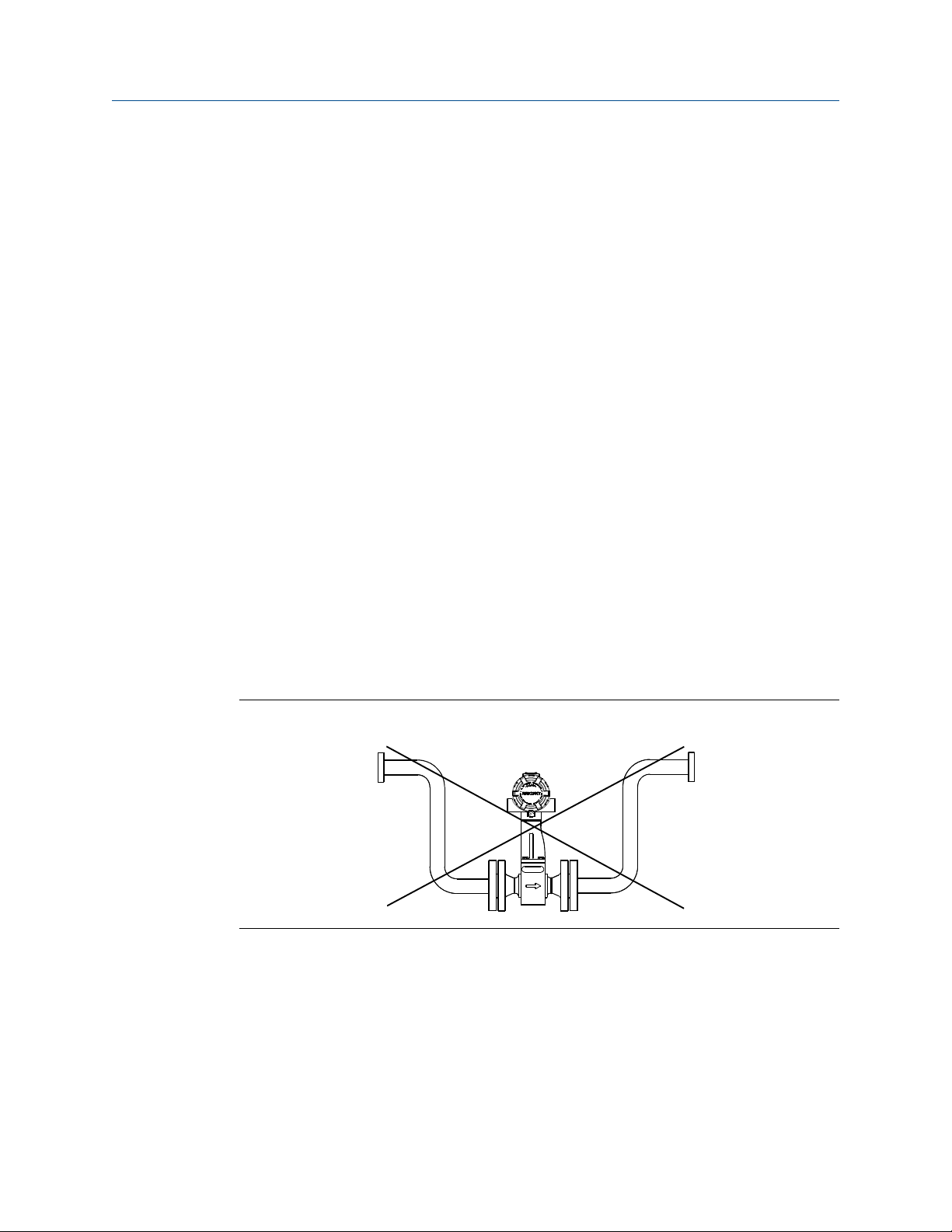
Steam piping
For steam applications, avoid installations such as the one shown in the following figure.
Such installations may cause a water-hammer condition at start-up due to trapped
condensation. The high force from the water hammer can stress the sensing mechanism
and cause permanent damage to the sensor.
Figure 3-5: Wrong steam pipe installation
Pressure and temperature transmitter location
When using pressure and temperature transmitters in conjunction with the vortex flow
meter for compensated mass flows, install the transmitter(s) downstream of the vortex
flow meter.
14 Rosemount™ 8800D Series Vortex Flow Meter with Modbus Protocol

Reference Manual Pre-installation
00809-0400-4004 October 2021
Figure 3-6: Pressure and temperature transmitter location
C
A
B
D
A. Pressure transmitter
B. Four straight pipe diameters downstream
C. Temperature transmitter
D. Six straight pipe diameters downstream
3.1.5
Power supply
The transmitter requires 10 to 30 VDC. The maximum power consumption is 0.4 W.
3.2 Commissioning
For proper configuration and operation, commission the meter before putting it into
operation. Bench commissioning also enables you to check hardware settings, test the
flowmeter electronics, verify flowmeter configuration data, and check output variables.
Any problems can be corrected—or configuration settings changed—before going out into
the installation environment. To commission on the bench, connect a configuration
device to the signal loop in accordance the device instructions.
3.2.1
Alarm and security jumper configuration
Two jumpers on the transmitter specify the alarm and security modes. Set these jumpers
during the commissioning stage to avoid exposing the electronics to the plant
environment. The two jumpers can be found on the electronics board stack or on the LCD
display.
Alarm
Security
The jumper setting for Alarm has no effect when the HART address is set to 1,
which is the required setting for the transmitter when configured for use on a
Modbus network.
You can protect the configuration data with the security lockout jumper. With
the security lockout jumper ON, any configuration changes attempted on the
electronics are disallowed. You can still access and review any of the operating
parameters and scroll through the available parameters, but no changes can
be made. The factory sets the jumper according to the Configuration Data
Sheet, if applicable, or OFF by default.
Reference Manual 15

Pre-installation Reference Manual
October 2021 00809-0400-4004
Note
If you will be changing configuration variables frequently, it may be useful to
leave the security lockout jumper in the OFF position to avoid exposing the
flow meter electronics to the plant environment.
To access the jumpers, remove the transmitter electronics housing or the LCD cover (if
equipped) opposite of the terminal block, See Figure 3-7 and Figure 3-8.
Figure 3-7: Alarm and security jumpers (no LCD option)
VORTEX
4-20mA
HART
TEST FREQ
IN
3.2.2
TP1
Figure 3-8: Alarm and security jumpers (with LCD option)
HI LO
HI LO
ALARM
ALARM
FLOW
SECURITY
SECURITY
ON OFF
ON OFF
Calibration
The flow meter is wet-calibrated at the factory and needs no further calibration during
installation. The calibration factor (K-factor) is indicated on each meter body and is
entered into the electronics. Verification can be accomplished with a configuration device.
16 Rosemount™ 8800D Series Vortex Flow Meter with Modbus Protocol

Reference Manual Basic installation
00809-0400-4004 October 2021
4 Basic installation
4.1 Handling
Handle all parts carefully to prevent damage. Whenever possible, transport the system to
the installation site in the original shipping containers. Keep the shipping plugs in the
conduit connections until you are ready to connect and seal them.
NOTICE
To avoid damage to the meter, do not lift the flow meter by the transmitter. Lift the meter
by the meter body. Lifting supports can be tied around the meter body as shown.
Figure 4-1: Lifting supports
4.2 Flow direction
The meter can only measure flow in the direction indicated on the meter body. Be sure to
mount the meter body so the FORWARD end of the flow arrow points in the direction of
the flow in the pipe.
4.3 Gaskets
The flow meter requires gaskets supplied by the user. Be sure to select gasket material
that is compatible with the process fluid and pressure ratings of the specific installation.
Note
Ensure the inside diameter of the gasket is larger than the inside diameter of the flow
meter and adjacent piping. If gasket material extends into the flow stream, it will disturb
the flow and cause inaccurate measurements.
Reference Manual 17

Basic installation Reference Manual
October 2021 00809-0400-4004
4.4 Insulation
Insulation should extend to the end of the bolt on the bottom of the meter body and
should leave at least 1-in. (25 mm) of clearance around the electronics bracket. The
electronics bracket and electronics housing should not be insulated. See Figure 4-2.
Figure 4-2: Insulation best practice to prevent electronics overheating
A. Support tube
CAUTION
In high temperature installations, to avoid damage to the electronics on integral units or
to the remote cable on remote units, only insulate the meter body as shown. Do not
insulate the support tube. See also Orientation.
4.5 Flanged-style flow meter mounting
Most vortex flow meters use a flanged-style process connection. Physical mounting of a
flanged-style flow meter is similar to installing a typical section of pipe. Conventional
tools, equipment, and accessories (such as bolts and gaskets) are required. Tighten the
nuts following the sequence shown in Figure 4-4.
Note
The required bolt load for sealing the gasket joint is affected by several factors, including
operating pressure and gasket material, width, and condition. A number of factors also
affect the actual bolt load resulting from a measured torque, including condition of bolt
threads, friction between the nut head and the flange, and parallelism of the flanges. Due
to these application-dependent factors, the required torque for each application may be
different. Follow the guidelines outlined in ASME PCC-1 for proper bolt tightening. Make
sure the flow meter is centered between flanges of the same nominal size and rating as
the flow meter.
18 Rosemount™ 8800D Series Vortex Flow Meter with Modbus Protocol

Reference Manual Basic installation
00809-0400-4004 October 2021
Figure 4-3: Flanged-style flow meter installation
A. Installation studs and nuts (supplied by customer)
B. Gaskets (supplied by customer)
C. Flow
Figure 4-4: Flange bolt torquing sequence
Reference Manual 19

Basic installation Reference Manual
October 2021 00809-0400-4004
4.6 Wafer-style flow meter alignment and mounting
Center the wafer-style meter body inside diameter with respect to the inside diameter of
the adjoining upstream and downstream piping. This will ensure the flow meter achieves
its specified accuracy. Alignment rings are provided with each wafer-style meter body for
centering purposes. Follow these steps to align the meter body for installation. Refer to
Figure 4-5.
1. Place the alignment rings over each end of the meter body.
2. Insert the studs for the bottom side of the meter body between the pipe flanges.
3. Place the meter body (with alignment rings) between the flanges.
• Make sure the alignment rings are properly placed onto the studs.
• Align the studs with the markings on the ring that correspond to the flange you
are using.
Note
Be sure to align the flow meter so the electronics are accessible, the conduits drain,
and the flow meter is not subject to direct heat.
4. Place the remaining studs between the pipe flanges.
5. Tighten the nuts in the sequence shown in Figure 4-4.
6. Check for leaks at the flanges after tightening the flange bolts.
Note
The required bolt load for sealing the gasket joint is affected by several factors,
including operating pressure and gasket material, width, and condition. A number
of factors also affect the actual bolt load resulting from a measured torque,
including condition of bolt threads, friction between the nut head and the flange,
and parallelism of the flanges. Due to these application-dependent factors, the
required torque for each application may be different. Follow the guidelines
outlined in ASME PCC-1 for proper bolt tightening. Make sure the flow meter is
centered between flanges of the same nominal size and rating as the flow meter.
20 Rosemount™ 8800D Series Vortex Flow Meter with Modbus Protocol

Reference Manual Basic installation
00809-0400-4004 October 2021
Figure 4-5: Wafer-style flow meter installation with alignment rings
B
B
A
4.6.1
C
D
A. Installation studs and nuts (supplied by customer)
B. Alignment rings
C. Spacer (for Rosemount 8800D to maintain Rosemount 8800A dimensions)
D. Flow
Note
See for instructions on retrofitting 8800D to 8800A installations.
Stud bolts for wafer-style flow meters
The following tables list the recommended minimum stud bolt lengths for wafer-style
meter body size and different flange ratings.
Table 4-1: Stud bolt length for wafer-style flow meters with ASME B16.5 flanges
Line size Minimum recommended stud bolt lengths (in inches) for each flange
rating
Class 150 Class 300 Class 600
½-inch 6.00 6.25 6.25
1-inch 6.25 7.00 7.50
1½-inch 7.25 8.50 9.00
2-inch 8.50 8.75 9.50
3-inch 9.00 10.00 10.50
4-inch 9.50 10.75 12.25
6-inch 10.75 11.50 14.00
8-inch 12.75 14.50 16.75
Reference Manual 21

Basic installation Reference Manual
October 2021 00809-0400-4004
Table 4-2: Stud bolt length for wafer-style flow meters with EN 1092 flanges
Line size Minimum recommended stud bolt lengths (in mm) for each flange rating
PN 16 PN 40 PN 63 PN 100
DN 15 160 160 170 170
DN 25 160 160 200 200
DN 40 200 200 230 230
DN 50 220 220 250 270
DN 80 230 230 260 280
DN 100 240 260 290 310
DN 150 270 300 330 350
DN 200 320 360 400 420
Line size Minimum recommended stud bolt lengths (in mm) for each flange
rating
JIS 10k JIS 16k and 20k JIS 40k
15mm 150 155 185
25mm 175 175 190
40mm 195 195 225
50mm 210 215 230
80mm 220 245 265
100mm 235 260 295
150mm 270 290 355
200mm 310 335 410
4.7 Cable glands
If you are using cable glands instead of conduit, follow the cable gland manufacturer’s
instructions for preparation and make the connections in a conventional manner in
accordance with local or plant electrical codes. Be sure to properly seal unused ports to
prevent moisture or other contamination from entering the terminal block compartment
of the electronics housing.
4.8 Flow meter grounding
Grounding is not required in typical vortex applications; however, a proper ground will
eliminate possible noise pickup by the electronics. Grounding straps may be used to
ensure that the meter is grounded to the process piping. If you are using the transient
protection option (T1), grounding straps are required to provide a proper low impedance
ground.
22 Rosemount™ 8800D Series Vortex Flow Meter with Modbus Protocol

Reference Manual Basic installation
00809-0400-4004 October 2021
Note
Properly ground flow meter body and transmitter per the local code.
To use grounding straps, secure one end of the grounding strap to the bolt extending from
the side of the meter body and attach the other end of each grounding strap to a suitable
ground. See Figure 4-6.
Figure 4-6: Grounding connections
A. Internal ground connection
B. External ground assembly
4.9 Grounding the transmitter case
The transmitter case should always be grounded in accordance with national and local
electrical codes. The most effective transmitter case grounding method is direct
connection to earth ground with minimal impedance. Methods for grounding the
transmitter case include:
Internal
Ground
Connection
External
Ground
Assembly
Note
Grounding the transmitter case using the threaded conduit connection may not provide a
sufficient ground. The transient protection terminal block (Option Code T1) does not
provide transient protection unless the transmitter case is properly grounded. For
transient terminal block grounding, see Transient protection. Use the above guidelines to
The Internal Ground Connection screw is inside the FIELD TERMINALS
side of the electronics housing. This screw is identified by a ground
symbol ( ), and is standard on all Rosemount 8800D transmitters.
This assembly is located on the outside of the electronics housing and
is included with the optional transient protection terminal block
(Option Code T1). The External Ground Assembly can also be ordered
with the transmitter (Option Code V5) and is automatically included
with certain hazardous area approvals. See Figure 4-6 for the location
of the external ground assembly.
Reference Manual 23

Basic installation Reference Manual
October 2021 00809-0400-4004
ground the transmitter case. Do not run the transient protection ground wire with signal
wiring as the ground wire may carry excessive electric current if a lightning strike occurs.
4.10 Conduit installation
Prevent condensation in any conduit from flowing into the housing by mounting the
flowmeter at a high point in the conduit run. If the flowmeter is mounted at a low point in
the conduit run, the terminal compartment could fill with fluid.
If the conduit originates above the flowmeter, route conduit below the flowmeter to form
a drip loop before entry. In some cases a drain seal may need to be installed.
Figure 4-7: Proper conduit installation
A A
A. Conduit line
4.11 Wiring
1. Supply 10–30 VDC to the positive (+) and negative (–) terminals. The power
terminals are polarity insensitive: the polarity of the DC power leads does not
matter when connecting to the power terminals.
24 Rosemount™ 8800D Series Vortex Flow Meter with Modbus Protocol

Reference Manual Basic installation
00809-0400-4004 October 2021
Figure 4-8: Modbus and power supply wiring
C
A. RS-485 (A)
B. RS-485 (B)
C. 10–30 VDC power supply
2. Connect Modbus RTU communication wires to the Modbus A and B terminals.
Note
Twisted pair wiring is required for RS-485 bus wiring. Wiring runs under 1000 ft
(305 m) should be AWG 22 or larger. Wiring runs from 1000 to 4000 ft. (305 to
1219 m) should be AWG 20 or larger. Wiring should not exceed AWG 16.
4.12 Remote installation
If a remote electronics option (Rxx or Axx) was ordered, the flow meter assembly will be
shipped in two parts:
• The meter body with an adapter installed in the support tube and an interconnecting
coaxial cable attached to it.
B
A
• The electronics housing installed on a mounting bracket.
If an armored remote electronics option (Axx) was ordered, follow the same instructions as
for the standard remote cable connection with the exception that the cable may not need
to be run through conduit. Both standard and armored cable include cable glands.
Information on remote installation can be found in Cable connections.
4.12.1
Reference Manual 25
Mounting
Mount the meter body in the process flow line as described earlier in this section. Mount
the bracket and electronics housing in the desired location. The housing can be
repositioned on the bracket to facilitate field wiring and conduit routing.

Basic installation Reference Manual
October 2021 00809-0400-4004
4.12.2 Cable connections
Complete these steps for connecting the loose end of the coaxial cable to the electronics
housing. If connecting/disconnecting the meter adapter to the meter body,.
Figure 4-9: Remote installation
A
B
C
D
E
F
G
H
P
O
N
J
K
I
M
L
A. ½ NPT conduit adapter or cable gland (supplied by customer for Rxx options)
B. Coaxial cable
C. Meter adapter
D. Union
E. Washer
F. Nut
G. Sensor cable nut
H. Support tube
I. Meter body
J. Electronics housing
K. Coaxial cable SMA nut
L. ½ NPT conduit adapter or cable gland (supplied by customer for Rxx options)
M. Housing adapter screws
N. Housing adapter
O. Housing base screw (one of four)
P. Ground connection
26 Rosemount™ 8800D Series Vortex Flow Meter with Modbus Protocol

Reference Manual Basic installation
00809-0400-4004 October 2021
CAUTION
To prevent moisture from entering the coaxial cable connections, install the
interconnecting coaxial cable in a single dedicated conduit run or use sealed cable
glands at both ends of the cable.
In remote mount configurations when ordered with a hazardous area option code, the
remote sensor cable and the interconnecting thermocouple cable are protected by
separate intrinsic safety circuits, and must be segregated from each other, other
intrinsically safe circuits, and non-intrinsically safe circuits per local and national wiring
code.
CAUTION
The coaxial remote cable cannot be field terminated or cut to length. Coil any extra
coaxial cable with no less than a 2-in. (51 mm) radius.
1. If you plan to run the coaxial cable in conduit, carefully cut the conduit to the
desired length to provide for proper assembly at the housing. A junction box may
be placed in the conduit run to provide a space for extra coaxial cable length.
2. Slide the conduit adapter or cable gland over the loose end of the coaxial cable and
fasten it to the adapter on the meter body support tube. If coaxial remote cable
originates or any part of the cable is above the flow meter, route cable below the
flow meter to form a drip loop before the meter body support tube.
3. If using conduit, route the coaxial cable through the conduit.
4. Place a conduit adapter or cable gland over the end of the coaxial cable.
5. Remove the housing adapter from the electronics housing.
6. Slide the housing adapter over the coaxial cable.
7. Remove one of the four housing base screws.
8. Attach the coaxial cable ground wire to the housing via the housing base ground
screw.
9. Attach and hand tighten the coaxial cable SMA nut to the electronics housing to 7
in-lbs (0.8 N-m).
Reference Manual 27

Basic installation Reference Manual
October 2021 00809-0400-4004
Figure 4-10: Attaching and tightening SMA nut
A
B
A. SMA nut
B. Hand tighten
Note
Do not over-tighten the coaxial cable nut to the electronics housing.
4.12.3
10. Align the housing adapter with the housing and attach with two screws.
11. Tighten the conduit adapter or cable gland to the housing adapter.
Housing rotation
The entire electronics housing may be rotated in 90° increments for easy viewing. Use the
following steps to change the housing orientation,
1. Loosen the housing rotation set screws at the base of the electronics housing with a
5/32” hex wrench by turning the screws clockwise (inward) until they clear the
support tube.
2. Slowly pull the electronics housing out of the support tube.
CAUTION
Do not pull the housing more than 1.5 in. (40 mm) from the top of the support
tube until the sensor cable is disconnected. Damage to the sensor may occur if
this sensor cable is stressed.
3. Unscrew the sensor cable from the housing with a 5/16” open end wrench.
4. Rotate the housing to the desired orientation.
5. Hold it in this orientation while you screw the sensor cable onto the base of the
housing.
CAUTION
Do not rotate the housing while the sensor cable is attached to the base of the
housing. This will stress the cable and may damage the sensor.
6. Place the electronics housing into the top of the support tube.
28 Rosemount™ 8800D Series Vortex Flow Meter with Modbus Protocol

Reference Manual Basic installation
00809-0400-4004 October 2021
7. Use a hex wrench to turn the housing rotation screws counter-clockwise (outward)
to engage the support tube.
4.12.4 Specifications and requirements for remote sensor cable
If using a Rosemount remote sensor cable, observe these specifications and requirements.
• The remote sensor cable is a proprietary design tri-axial cable
• It is considered a low voltage signal cable
• It is rated for and/or part of intrinsically safe installations
• Non armored version is designed to be run through metal conduit
• Cable is water resistant, but not submersible. As a best practice, exposure to moisture
should be avoided if possible
• Rated operating temperature is –58°F to +392°F (–50°C to +200°C)
• Flame Resistant in accordance with IEC 60332-3
• Non-armored and armored version minimum bend diameter is 8 inches (203 mm)
• Nominal O.D. of the non-armored version is 0.160 inches (4 mm)
• Nominal O.D. of the armored version is 0.282 inches (7.1 mm)
Figure 4-11: Non-armored cable
A. Transmitter end
B. Sensor end
C. Minimum bend diameter
D. Nominal O.D.
Reference Manual 29

Basic installation Reference Manual
October 2021 00809-0400-4004
Figure 4-12: Armored cable
A. Transmitter end
B. Sensor end
C. Minimum bend diameter
4.13 Quad transmitter numbering and orientation
When quad vortex flow meters are ordered, for configuration purposes, the transmitters
are identified as Transmitter 1, Transmitter 2, Transmitter 3, and Transmitter 4. The
transmitter and meter body nameplate of a Quad Vortex flow meter can be used to
identify and verify the transmitter number. See Figure 4-13 for Quad transmitter
orientation and nameplate locations. See Figure 4-14 and 4-15 for Quad transmitter and
meter body nameplate number location.
30 Rosemount™ 8800D Series Vortex Flow Meter with Modbus Protocol
 Loading...