

Reference Manual: Rosemount 3051 Pressure Transmitter with Foundation(TM) Fieldbus Protocol
Table of contents
 Loading...
Rosemount Reference Manual: Rosemount 3051 Pressure Transmitter with Foundation(TM) Fieldbus Protocol Manuals & Guides

Reference Manual
00809-0100-4774, Rev DB
Rosemount™ 3051 Pressure Transmitter
with FOUNDATION™ Fieldbus Protocol
July 2020

Safety messages
NOTICE
Read this manual before working with the product. For personal and system safety and for optimum product performance, ensure
you thoroughly understand the contents before installing, using, or maintaining this product.
For technical assistance, contacts are listed below:
Customer Central (Technical support, quoting, and order-related questions.)
• United States: 1-800-999-9307 (7:00 am to 7:00 pm Central Time)
• Asia Pacific: 65 777 8211
• Europe/Middle East/Africa: 49 (8153) 9390
North American Response Center (Equipment service needs.): 1-800-654-7768 (24 hours - includes Canada)
Outside of these areas, contact your local Emerson representative.
WARNING
Explosions
Explosions could result in death or serious injury.
In an explosion-proof/flameproof installation, do not remove the transmitter covers when power is applied to the unit.
Installation of device in an explosive environment must be in accordance with appropriate local, national, and international
standards, codes, and practices. Review the Product Certifications section of the Rosemount 3051 Product Data Sheet for any
restrictions associated with a safe installation.
Before connecting a handheld communicator in an explosive atmosphere, ensure the instruments are installed in accordance
with intrinsically safe or non-incendive field wiring practices.
Process leaks
Process leaks may cause harm or result in death.
Install and tighten process connectors before applying pressure.
Do not attempt to loosen or remove flange bolts while the transmitter is in service.
Electrical shock
Electrical shock can result in death or serious injury.
Avoid contact with the leads and terminals. High voltage that may be present on leads can cause electrical shock.
Replacement equipment
Replacement equipment or spare parts not approved by Emerson for use as spare parts could reduce the pressure retaining
capabilities of the transmitter and may render the instrument dangerous.
Use only bolts supplied or sold by Emerson as spare parts.
Improper assembly
Improper assembly of manifolds to traditional flange can damage sensor module.
For safe assembly of manifold to traditional flange, bolts must break back plane of flange web (i.e., bolt hole) but must not
contact sensor module housing.
Severe changes in the electrical loop may inhibit HART Communication or the ability to reach alarm values. Therefore,
Rosemount absolutely cannot warrant or guarantee that the correct Failure alarm level (High or Low) can be read by the host
system at the time of annunciation.
Physical access
Unauthorized personnel may potentially cause significant damage to and/or misconfiguration of end users’ equipment. This could
be intentional or unintentional and needs to be protected against.
Physical security is an important part of any security program and fundamental to protecting your system. Restrict physical access
by unauthorized personnel to protect end users’ assets. This is true for all systems used within the facility.
2

CAUTION
Nuclear applications
The products described in this document are not designed for nuclear-qualified applications. Using non-nuclear qualified products
in applications that require nuclear-qualified hardware or products may cause inaccurate readings.
For information on Rosemount nuclear-qualified products, contact your local Emerson Sales Representative.
3

4

Reference Manual Contents
00809-0100-4774 July 2020
Contents
Chapter 1 Introduction.............................................................................................................. 7
1.1 Using this manual........................................................................................................................ 7
1.2 Models covered........................................................................................................................... 7
1.3 Host files......................................................................................................................................8
1.4 Product recycling/disposal...........................................................................................................8
Chapter 2 Configuration............................................................................................................ 9
2.1 Overview..................................................................................................................................... 9
2.2 Safety messages.......................................................................................................................... 9
2.3 Device capabilities..................................................................................................................... 21
2.4 Node address.............................................................................................................................22
2.5 General block information......................................................................................................... 22
2.6 Resource block.......................................................................................................................... 26
2.7 Basic device setup......................................................................................................................33
2.8 Analog input (AI) function block................................................................................................ 39
2.9 Advanced device setup.............................................................................................................. 44
Chapter 3 Hardware installation.............................................................................................. 57
3.1 Overview................................................................................................................................... 57
3.2 Safety messages........................................................................................................................ 57
3.3 Installation considerations.........................................................................................................58
3.4 Tagging..................................................................................................................................... 59
3.5 Installation procedures.............................................................................................................. 60
3.6 Rosemount 305, 306, and 304 manifolds.................................................................................. 71
Chapter 4 Electrical installation................................................................................................83
4.1 Overview................................................................................................................................... 83
4.2 Safety messages........................................................................................................................ 83
4.3 LCD display................................................................................................................................ 84
4.4 Configuring transmitter security and simulation........................................................................84
4.5 Electrical considerations............................................................................................................ 86
4.6 Wiring........................................................................................................................................87
Chapter 5 Operation and maintenance.....................................................................................93
5.1 Overview................................................................................................................................... 93
5.2 Safety messages........................................................................................................................ 93
5.3 Calibration overview..................................................................................................................94
5.4 Trim the pressure signal.............................................................................................................97
5.5 Status...................................................................................................................................... 100
5.6 Master reset method............................................................................................................... 100
Reference Manual 5

Contents Reference Manual
July 2020 00809-0100-4774
5.7 Simulation............................................................................................................................... 101
Chapter 6 Troubleshooting.................................................................................................... 103
6.1 Overview................................................................................................................................. 103
6.2 Safety messages...................................................................................................................... 103
6.3 Disassembly procedures.......................................................................................................... 104
6.4 Reassemble............................................................................................................................. 106
6.5 Troubleshooting guides...........................................................................................................109
6.6 Troubleshooting and diagnostic messages.............................................................................. 111
6.7 Analog input (AI) function block.............................................................................................. 115
6.8 Service support........................................................................................................................116
Chapter 7 Advanced pressure diagnostics.............................................................................. 119
7.1 Overview................................................................................................................................. 119
7.2 Process Intelligence................................................................................................................. 119
7.3 PIL diagnostics.........................................................................................................................120
7.4 Process Intelligence technology...............................................................................................120
7.5 SPM configuration and operation.............................................................................................124
7.6 Plugged impulse line detection using SPM...............................................................................130
Appendix A Reference data....................................................................................................... 137
A.1 Ordering information, specifications, and drawings.................................................................137
A.2 Product certifications.............................................................................................................. 137
Appendix B Field Communicator............................................................................................... 139
B.1 Field Communicator menu trees..............................................................................................139
B.2 Field Communicator Fast Keys................................................................................................. 144
6 Rosemount 3051

Reference Manual Introduction
00809-0100-4774 July 2020
1 Introduction
1.1 Using this manual
The sections in this manual provide information on configuring, installing, operating and
maintaining, and troubleshooting Rosemount 3051 Pressure Transmitters specifically for
FOUNDATION™ Fieldbus protocol.
Configuration provides instruction on commissioning and operating the transmitters. It
also includes information on software functions, configuration parameters, and online
variables.
Hardware installation contains mechanical installation instructions.
Electrical installation contains electrical installation instructions.
Operation and maintenance provides detailed information on calibrating the transmitter.
Troubleshooting provides troubleshooting techniques for the most common operating
problems.
Reference data provides information on how to access specifications, ordering
information,and dimensional drawings.
Field Communicator menu trees and fast keys provides full menu trees and abbreviated
Fast Key sequences for commissioning tasks.
1.2 Models covered
The following Rosemount 3051 Transmitters are covered by this manual:
• Rosemount 3051C Coplanar™ Pressure Transmitter
— Measures differential and gage pressure up to 2000 psi (137.9 bar).
— Measures absolute pressure up to 4000 psia (275.8 bar).
• Rosemount 3051T In-Line Pressure Transmitter
— Measures gage/absolute pressure up to 10000 psi (689.5 bar).
• Rosemount 3051L Liquid Level Transmitter
— Measures level and specific gravity up to 300 psi (20.7 bar).
• Rosemount 3051CF Series Flowmeter
— Measures flow in line sizes from ½-in. (15 mm) to 96-in. (2400 mm).
Note
For transmitter with 4-20 mA HART® Revision 5 and 7 Selectable Protocol, see Rosemount
3051 Reference Manual.
For transmitter with PROFIBUS® PA, see Rosemount 3051 Reference Manual.
Reference Manual 7

Introduction Reference Manual
July 2020 00809-0100-4774
1.3 Host files
Before configuring the device, ensure the host has the appropriate Device Description
(DD) or Device Type Manager (DTM™) file revision for this device. The device descriptor
can be found on Fieldbus.org. The DTM can be found at Emerson.com. The current release
of the Rosemount 3051 with Foundation Fieldbus protocol is device revision 8. This
manual is for revision 8.
1.4 Product recycling/disposal
Consider recycling equipment. Dispose of packaging in accordance with local and national
legislations/regulations.
8 Rosemount 3051

Reference Manual Configuration
00809-0100-4774 July 2020
2 Configuration
2.1 Overview
This section contains information on commissioning and tasks that should be performed
on the bench prior to installation, as well as tasks performed after installation.
2.2 Safety messages
Procedures and instructions in this section may require special precautions to ensure the
safety of the personnel performing the operations.
WARNING
Explosions
Explosions could result in death or serious injury.
Before connecting a handheld communicator in an explosive atmosphere, ensure that
the instruments in the loop are installed in accordance with intrinsically safe or nonincendive field wiring practices.
In an explosion-proof/flameproof installation, do not remove the transmitter covers
when power is applied to the unit.
Process leaks
Install and tighten process connectors before applying pressure.
Electrical shock
Avoid contact with the leads and terminals. High voltage that may be present on leads
can cause electrical shock.
Static electricity
Observe safe handling precautions for static-sensitive components.
Conduit/cable entries
Unless marked, the conduit/cable entries in the transmitter housing use a ½–14 NPT
thread form. Entries marked “M20” are M20 × 1.5 thread form. On devices with multiple
conduit entries, all entries will have the same thread form. Only use plugs, adapters,
glands, or conduit with a compatible thread form when closing these entries.
When installing in a hazardous location, use only appropriately listed or Ex certified plugs,
glands, or adapters in cable/conduit entries.
Reference Manual 9

Configuration Reference Manual
July 2020 00809-0100-4774
WARNING
Replacement parts
Replacement equipment or spare parts not approved by Emerson for use as spare parts
could reduce the pressure retaining capabilities of the transmitter and may render the
instrument dangerous.
Use only bolts supplied or sold by Emerson as spare parts.
Improper assembly
Improper assembly of manifolds to traditional flange can damage sensor module.
For safe assembly of manifold to traditional flange, bolts must break back plane of
flange web (i.e., bolt hole) but must not contact sensor module housing.
Severe changes in the electrical loop may inhibit HART® communication or the ability
to reach alarm values. Therefore, Rosemount cannot absolutely warrant or guarantee
that the correct Failure alarm level (High or Low) can be read by the host system at the
time of annunciation.
2.2.1
Physical access
Unauthorized personnel may potentially cause significant damage to and/or
misconfiguration of end users’ equipment. This could be intentional or unintentional and
needs to be protected against.
Physical security is an important part of any security program and fundamental to
protecting your system. Restrict physical access by unauthorized personnel to protect end
users’ assets. This is true for all systems used within the facility.
Device Description (DD) and Device Type Manager (DTM™) based interfaces
The Rosemount 3051Pressure Transmitter Rev 8 has both DD based and DTM based user
interfaces available. All device configuration and maintenance tasks can be performed
using either technology.
The DD capabilities supported will vary based on host supplier and host revision. Check
with your host supplier to determine and obtain the appropriate DD for your situation. The
type of DD your host supports may influence navigation between different functions, and
the exact steps used to perform different tasks. The device menu tree has multiple ways to
navigate between and perform tasks. Not all ways will be usable on all hosts, but at least
one way will be usable on every host.
2.2.2
10 Rosemount 3051
Device menu tree
Device information and device tasks are organized in a menu tree structure. The complete
menu tree is shown in Figure 2-9. A partial menu tree covering the most common device
tasks is shown in Figure 2-10.

Reference Manual Configuration
00809-0100-4774 July 2020
2.2.3 Basic organization
Device information and tasks are organized into three different menu tree branches. They
are Overview, Configure, and Service Tools. Information and tasks may be resident in more
than a single branch of the menu tree.
The device menu tree is the landing screen for the Handheld user interface. The device
menu tree is also permanently displayed on PC-based user interfaces. On PC-based user
interfaces, you can expand or collapse the menu tree as needed to facilitate navigation.
The same device menu tree applies for both handheld and PC-based user interfaces. On
the handheld, each menu tree entry has a dedicated screen (see Figure 2-3). On PC-based
user interfaces, several menu tree entries may be displayed on a single screen with each
menu tree entry used as the heading for a section of that screen (see Figure 2-2). The net
result is that you can use the menu tree to navigate all DD’s and DTM’s; however, you may
need to perform actions on one screen or several screens to perform the same task.
Figure 2-1: Configure Device Alerts-Multiple Screens
On devices with smaller screens the information and parameters necessary to complete a
task may be divided into several screens. In this figure, each category of alert to be
configured has a dedicated screen shown. There are four total screens used for alert
configuration.
Reference Manual 11
2YHUYLHZ
&RQILJXUH
6HUYLFH7RROV
Configuration Reference Manual
July 2020 00809-0100-4774
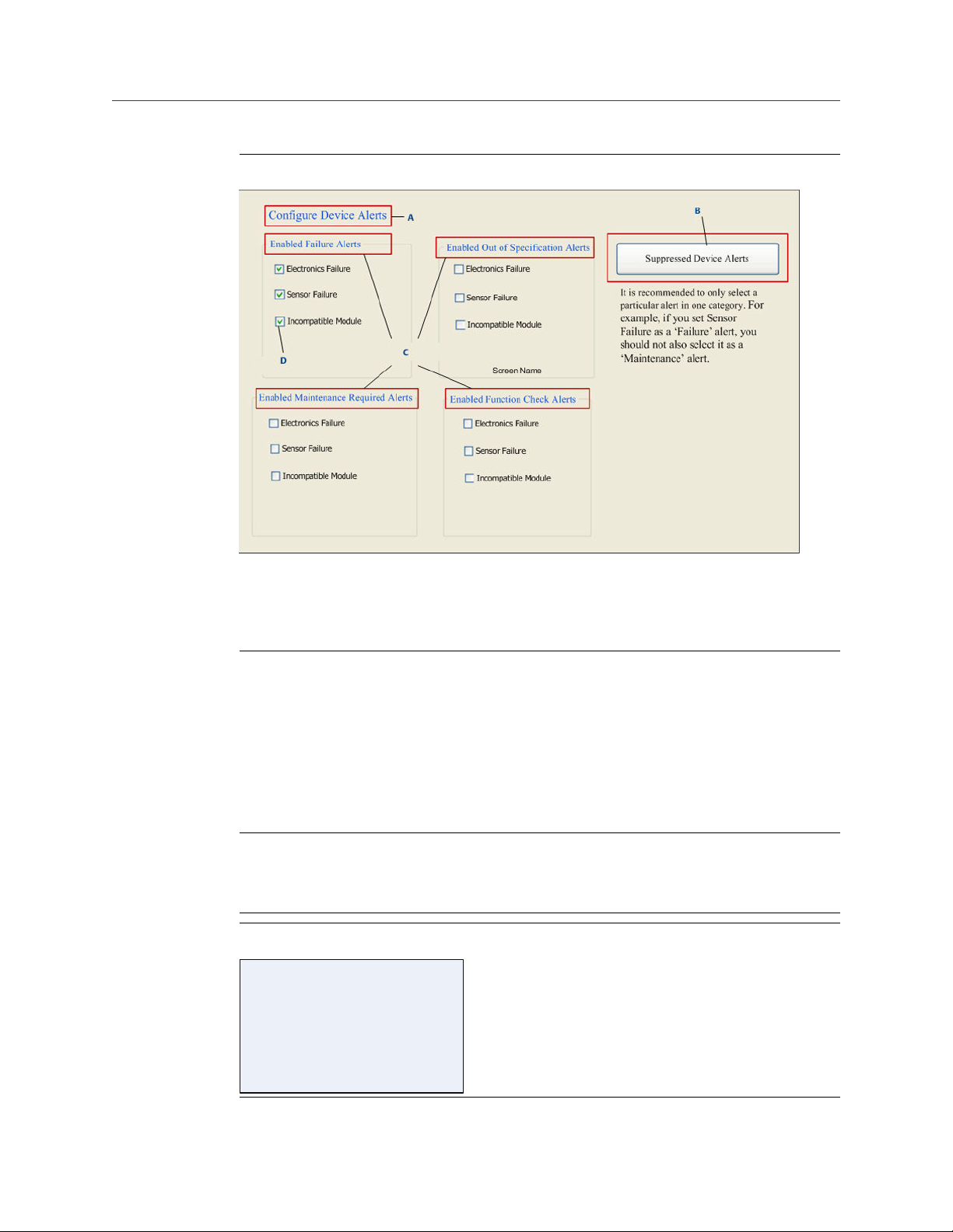
Figure 2-2: Configure Device Alerts-Single Screen
2.2.4
A. Screen name
B. Configure Suppressed Alerts button
C. Status signal categories
D. Alert check boxes
On this PC-based configuration screen, alert configuration for all four alert categories is
performed on a single screen.
Home screen
The Home screen provides access to the three main branches of the menu tree. These
branches are Overview, Configure, and Service Tools. From this screen, select any of the
three main branches to access detailed device functionality.
Note
Some tasks can be performed from multiple locations on the menu tree. This is done to
allow you to perform related tasks with a minimum of screen changes and keystrokes. The
organization of the device menu tree is further described below.
Figure 2-3: Home Screen
12 Rosemount 3051
2YHUYLHZ
&RQILJXUH
6HUYLFH7RROV
2YHUYLHZ
3UHVVXUH
&DOLEUDWLRQ
'HYLFH,QIRUPDWLRQ
/RFDWH'HYLFH
6FDOH*DXJHV
&DOLEUDWLRQ
3ULPDU\9DOXH
6HQVRU7ULP
6HQVRU/LPLWV
5HVWRUH)DFWRU\&DOLEUDWLRQ
/DVW&DOLEUDWLRQ3RLQWV
&DOLEUDWLRQ'HWDLOV
'HYLFH,QIRUPDWLRQ
,GHQWLILFDWLRQ
5HYLVLRQV
0DWHULDOVRI&RQVWUXFWLRQ
6HFXULW\6LPXODWLRQ
0DWHULDOVRI&RQVWUXFWLRQ
6HQVRU
6HQVRU5DQJH
)ODQJH
5HPRWH6HDO
6HFXULW\6LPXODWLRQ
:ULWH/RFN6HWXS
3ULPDU\9DOXH
&KDQJH'DPSLQJ
6HQVRU7ULP
8SSHU
/RZHU
=HUR
5HVWRUH
5HYLVLRQV
'HYLFH'ULYHU
( )
( )
&RQILJXUH
*XLGHG6HWXS
0DQXDO6HWXS
$OHUW6HWXS
*XLGHG6HWXS
=HUR7ULP
&KDQJH'DPSLQJ
/RFDO'LVSOD\6HWXS
&RQILJXUH$QDORJ,QSXW%ORFNV
%DVLF6306HWXS
Reference Manual Configuration
00809-0100-4774 July 2020
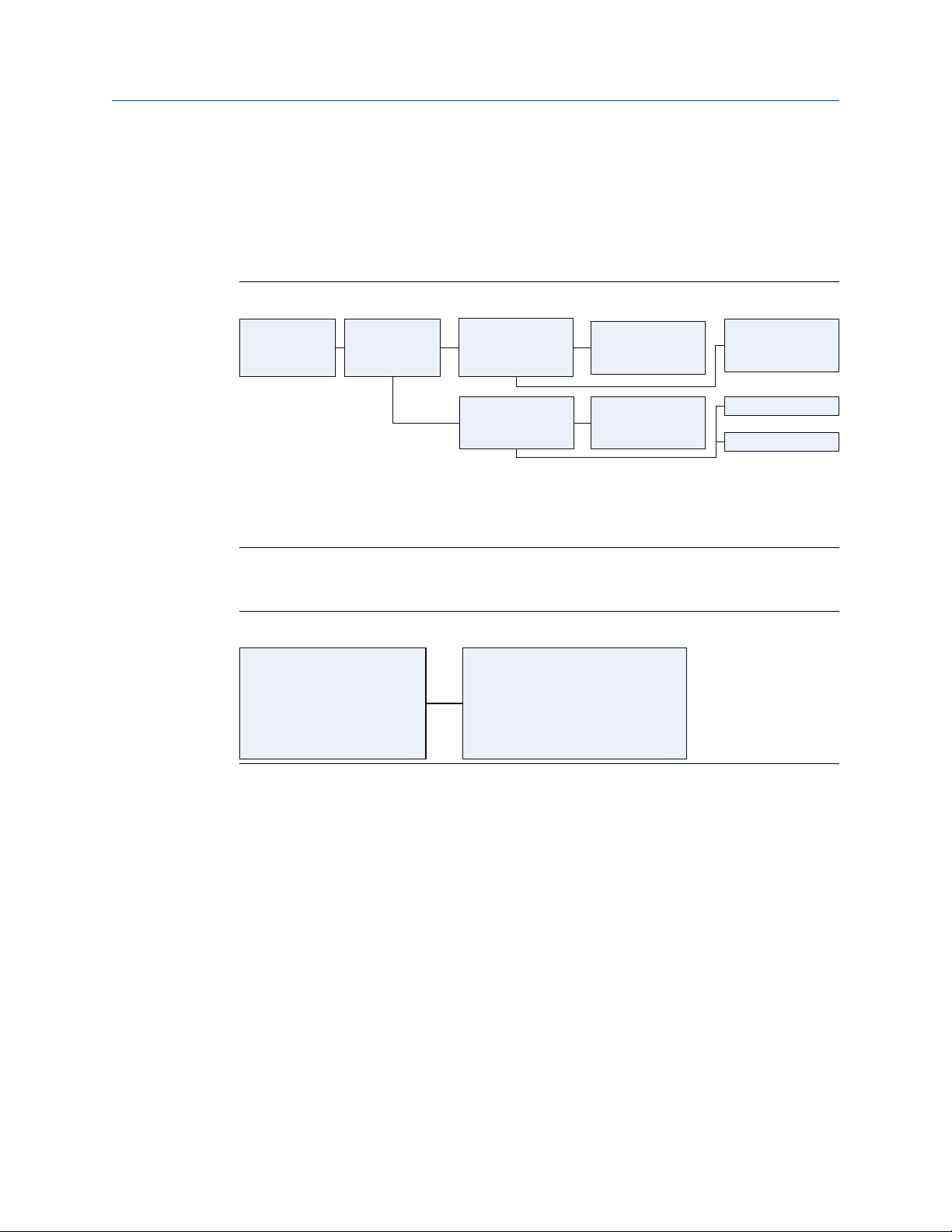
2.2.5 Overview
The Overview branch of the menu tree provides device information and single keystroke
shortcuts to view variables and device status, access device diagnostics, and perform basic
calibration functions. The Overview screen is the landing screen for PC-based user
interfaces.
Figure 2-4: Overview
Black text - Navigation selections available
(Text) - Name of selection used on parent menu screen to access this screen
2.2.6
Green text - Automated methods
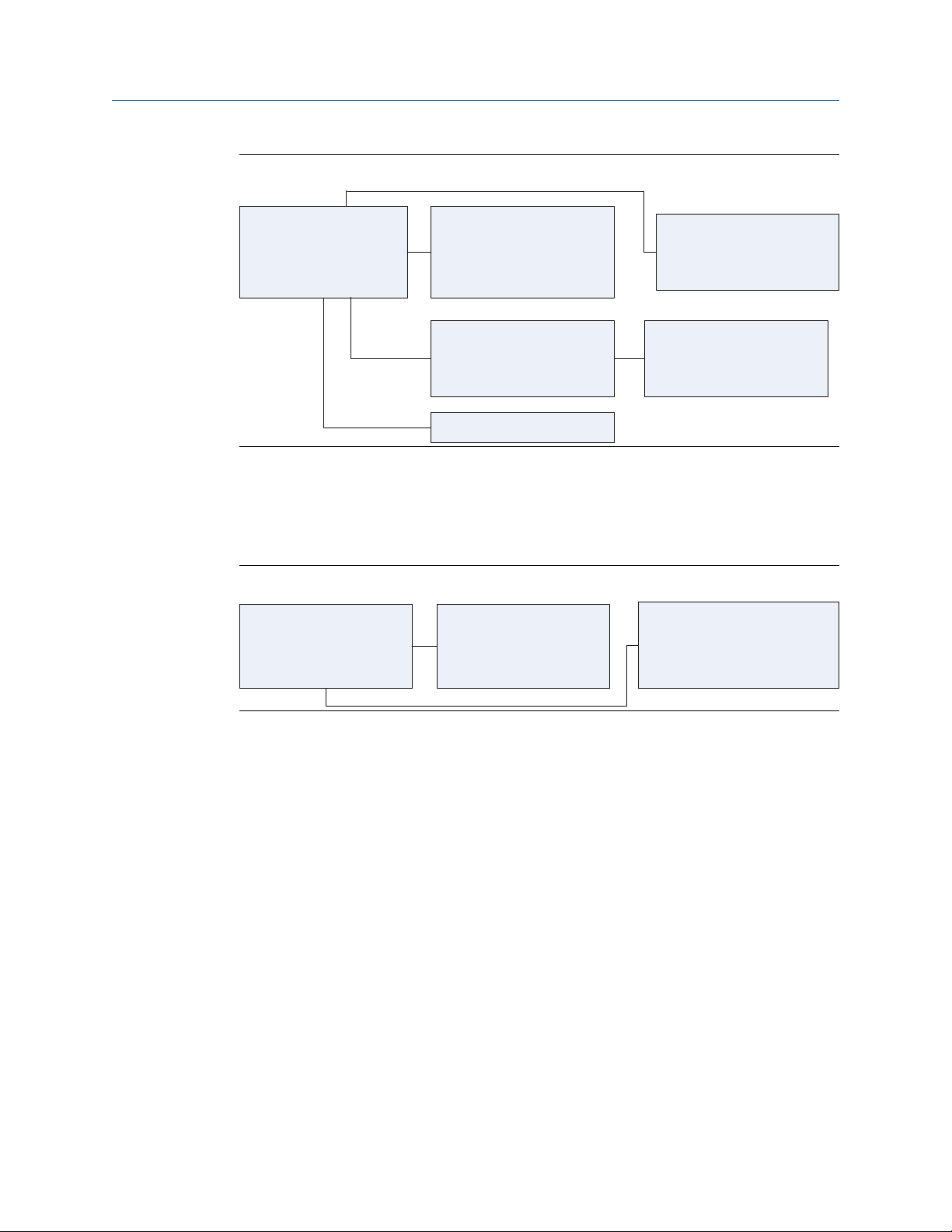
Configure
Figure 2-5: Guided Setup
The Configure branch of the menu tree provides both guided setup and manual setup.
Guided setup provides automated step by step methods for performing device
configuration. Manual setup provides user editable screens where you can perform a
configuration task by selecting or entering the necessary parameters without step by step
guidance.
Reference Manual 13
0DQXDO6HWXS
3URFHVV9DULDEOH
0DWHULDOVRI&RQVWUXFWLRQ
'LVSOD\
%DVLF630
&ODVVLF9LHZ
'LVSOD\
'LVSOD\2SWLRQV
$GYDQFHG&RQILJXUDWLRQ
$GYDQFHG&RQILJXUDWLRQ
'LVSOD\3DUDPHWHU
'LVSOD\3DUDPHWHU
'LVSOD\3DUDPHWHU
'LVSOD\3DUDPHWHU
%DVLF630
&RQILJXUDWLRQ
0DWHULDOVRI&RQVWUXFWLRQ
6HQVRU
6HQVRU5DQJH
)ODQJH
5HPRWH6HDO
3URFHVV9DULDEOH
3UHVVXUH
3UHVVXUH'DPSLQJ
6HQVRU7HPSHUDWXUH
&KDQJH'DPSLQJ
&ODVVLF9LHZ
9LHZ$OO3DUDPHWHUV
0RGH6XPPDU\
0DVWHU5HVHW
9LHZ$OO3DUDPHWHUV
5HVRXUFH%ORFN
6HQVRU7UDQVGXFHU%ORFN
/&'%ORFN
630%ORFN
0RGH6XPPDU\
5HWXUQ$OOWR6HUYLFH
3XW$OO2XWRI6HUYLFH
5HVRXUFH%ORFNದ0RGH&KDQJH
6HQVRU7UDQVGXFHU%ORFNದ0RGH&KDQJH
/&'%ORFN0RGH&KDQJH
630%ORFNದ0RGH&KDQJH
Configuration Reference Manual
July 2020 00809-0100-4774
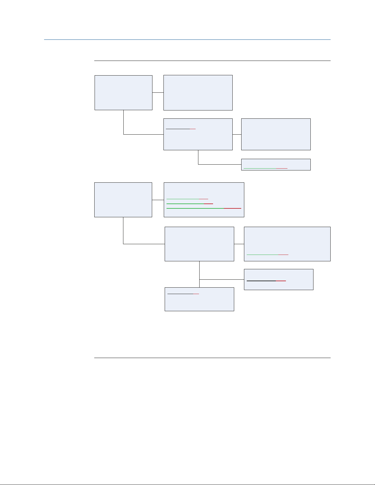
Figure 2-6: Manual Setup
Manual setup can take less time than guided setup if you are familiar with the task to be
performed. Manual setup also allows you to edit specific parameters without needing to
step through all the setup steps. If you are not familiar with a specific task, Emerson
™
recommends guided setup so task steps are done in the correct order and all needed steps
are performed.
Figure 2-7: Classic View
The Manual Setup branch also provides a view called classic view which lists block
parameters in a single scroll-down menu. Expert users may prefer this view for
configuration, as you can do multiple configuration tasks without leaving the single menu
screen.
14 Rosemount 3051

$OHUW6HWXS
'HYLFH$OHUWV
3URFHVV$OHUWV
'LDJQRVWLF$OHUWV
'HYLFH$OHUWV
(QDEOH)DLOXUH$OHUWV
(QDEOH2XWRI6SHFLILFDWLRQ$OHUWV
(QDEOH0DLQWHQDQFH5HTXLUHG$OHUWV
(QDEOH)XQFWLRQ&KHFN$OHUWV
6XSSUHVVHG'HYLFH$OHUWV
6XSSUHVVHG'HYLFH$OHUWV
)DLOXUH$OHUWV
2XWRI6SHFLILFDWLRQ$OHUWV
0DLQWHQDQFH5HTXLUHG$OHUWV
)XQFWLRQ&KHFN$OHUWV
3URFHVV$OHUWV
(QDEOH)DLOXUH$OHUWV
(QDEOH2XWRI6SHFLILFDWLRQ$OHUWV
(QDEOH0DLQWHQDQFH5HTXLUHG$OHUWV
(QDEOH)XQFWLRQ&KHFN$OHUWV
6XSSUHVVHG3URFHVV$OHUWV
'LDJQRVWLF$OHUWV
(QDEOH)DLOXUH$OHUWV
(QDEOH2XWRI6SHFLILFDWLRQ$OHUWV
(QDEOH0DLQWHQDQFH5HTXLUHG$OHUWV
(QDEOH)XQFWLRQ&KHFN$OHUWV
6XSSUHVVHG'HYLFH$OHUWV
6XSSUHVVHG3URFHVV$OHUWV
)DLOXUH$OHUWV
2XWRI6SHFLILFDWLRQ$OHUWV
0DLQWHQDQFH5HTXLUHG$OHUWV
)XQFWLRQ&KHFN$OHUWV
6XSSUHVVHG'LDJQRVWLF$OHUWV
)DLOXUH$OHUWV
2XWRI6SHFLILFDWLRQ$OHUWV
0DLQWHQDQFH5HTXLUHG$OHUWV
)XQFWLRQ&KHFN$OHUWV
Reference Manual Configuration
00809-0100-4774 July 2020
Figure 2-8: Alert Setup
Black text - Navigation selections available
(Text) Name of selection used on parent menu screen to access this screen
Green text - Automated methods
The final Configure branch supports alert setup. The same configuration process supports
both NE107 alerts (the factory default Device alerts), and PlantWeb® alerts. Note the
diagnostics performed and the recommended actions for NE107 alerts and Plantweb
alerts are identical. The only difference is that NE107 alerts and Plantweb alerts annunciate
the alerts using different categories.
NE107 requires device manufacturers to provide a way for you to enable, suppress, and recategorize alerts. NE107 alerts can be defined as any of four categories. They are Failure
Alerts, Out of Specification Alerts, Maintenance Required Alerts, and Function Check Alerts. To
minimize configuration tasks and time, the Rosemount 3051 ships from the factory with
alerts enabled and pre-categorized. Emerson recommends using factory default
categories if the defaults meet plant standards and there is no identified benefit to
changing categories.
Note
The NE107 specification allows a single alert to be included in multiple categories. As a
general practice, Emerson does not recommend this as alarm management can become
needlessly complex.
You can suppress NE107 alerts. If you configure an alert to reside in multiple categories,
you can suppress it in some categories, but not others. To completely suppress an alert,
you must suppress it in every category where it is configured.
Reference Manual 15

6HUYLFH7RROV
$OHUWV
9DULDEOHV
7UHQGV
%DVLF630
0DLQWHQDQFH
6LPXODWH
9DULDEOHV
3UHVVXUH
6HQVRU7HPSHUDWXUH
7UHQGV
3UHVVXUH
6HQVRU7HPSHUDWXUH
%DVLF630
0HDQ
6WDQGDUG'HYLDWLRQ
/DVW6WDWXV8SGDWH
6LPXODWH
6LPXODWH$OHUWV
(QDEOH'LVDEOH$OHUW6LPXODWLRQV
0DLQWHQDQFH
&DOLEUDWH
5HVHW5HVWRUH
&DOLEUDWH
3ULPDU\9DOXH
&KDQJH'DPSLQJ
6HQVRU7ULP
8SSHU/RZHU=HUR
5HVWRUH
6HQVRU/LPLWV
/DVW&DOLEUDWLRQ3RLQW
&DOLEUDWLRQ'HWDLOV
5HVHW5HVWRUH
0DVWHU5HVHW
5HVWRUH)DFWRU\&DO
Configuration Reference Manual
July 2020 00809-0100-4774
2.2.7 Service tools
Black text - Navigation selection available
(Text) - Name of selection used on parent menu screen to access this screen
Green text - Automated methods
The Service Tools branch of the menu tree allows you to perform typical device
maintenance tasks, simulate alerts and parameters, and perform some configuration
resets to return devices to as-manufactured settings.
16 Rosemount 3051

2YHUYLHZ
&RQILJXUH
6HUYLFH7RROV
2YHUYLHZ
3UHVVXUH
&DOLEUDWLRQ
'HYLFH,QIRUPDWLRQ
/RFDWH'HYLFH
6FDOH*DXJHV
&DOLEUDWLRQ
3ULPDU\9DOXH
6HQVRU7ULP
6HQVRU/LPLWV
5HVWRUH)DFWRU\&DOLEUDWLRQ
/DVW&DOLEUDWLRQ3RLQWV
&DOLEUDWLRQ'HWDLOV
'HYLFH,QIRUPDWLRQ
,GHQWLILFDWLRQ
5HYLVLRQV
0DWHULDOVRI&RQVWUXFWLRQ
6HFXULW\6LPXODWLRQ
0DWHULDOVRI&RQVWUXFWLRQ
6HQVRU
6HQVRU5DQJH
)ODQJH
5HPRWH6HDO
&RQILJXUH
*XLGHG6HWXS
0DQXDO6HWXS
$OHUW6HWXS
0DQXDO6HWXS
3URFHVV9DULDEOH
0DWHULDOVRI&RQVWUXFWLRQ
'LVSOD\
%DVLF630
&ODVVLF9LHZ
0DWHULDOVRI&RQVWUXFWLRQ
6HQVRU
6HQVRU5DQJH
)ODQJH
5HPRWH6HDO
'LVSOD\
'LVSOD\2SWLRQV
$GYDQFHG&RQILJXUDWLRQ
$GYDQFHG&RQILJXUDWLRQ
'LVSOD\3DUDPHWHU
'LVSOD\3DUDPHWHU
'LVSOD\3DUDPHWHU
'LVSOD\3DUDPHWHU
%DVLF630
&RQILJXUDWLRQ
&ODVVLF9LHZ
9LHZ$OO3DUDPHWHUV
0RGH6XPPDU\
0DVWHU5HVHW
9LHZ$OO3DUDPHWHUV
5HVRXUFH%ORFN
6HQVRU7UDQVGXFHU%ORFN
/&'%ORFN
630%ORFN
$OHUW6HWXS
'HYLFH$OHUWV
3URFHVV$OHUWV
'LDJQRVWLF$OHUWV
'HYLFH$OHUWV
(QDEOH)DLOXUH$OHUWV
(QDEOH2XWRI6SHFLILFDWLRQ$OHUWV
(QDEOH0DLQWHQDQFH5HTXLUHG$OHUWV
(QDEOH)XQFWLRQ&KHFN$OHUWV
6XSSUHVVHG'HYLFH$OHUWV
6XSSUHVVHG'HYLFH$OHUWV
)DLOXUH$OHUWV
2XWRI6SHFLILFDWLRQ$OHUWV
0DLQWHQDQFH5HTXLUHG$OHUWV
)XQFWLRQ&KHFN$OHUWV
3URFHVV$OHUWV
(QDEOH)DLOXUH$OHUWV
(QDEOH2XWRI6SHFLILFDWLRQ$OHUWV
(QDEOH0DLQWHQDQFH5HTXLUHG$OHUWV
(QDEOH)XQFWLRQ&KHFN$OHUWV
6XSSUHVVHG3URFHVV$OHUWV
'LDJQRVWLF$OHUWV
(QDEOH)DLOXUH$OHUWV
(QDEOH2XWRI6SHFLILFDWLRQ$OHUWV
(QDEOH0DLQWHQDQFH5HTXLUHG$OHUWV
(QDEOH)XQFWLRQ&KHFN$OHUWV
6XSSUHVVHG'HYLFH$OHUWV
6XSSUHVVHG3URFHVV$OHUWV
)DLOXUH$OHUWV
2XWRI6SHFLILFDWLRQ$OHUWV
0DLQWHQDQFH5HTXLUHG$OHUWV
)XQFWLRQ&KHFN$OHUWV
6XSSUHVVHG'LDJQRVWLF$OHUWV
)DLOXUH$OHUWV
2XWRI6SHFLILFDWLRQ$OHUWV
0DLQWHQDQFH5HTXLUHG$OHUWV
)XQFWLRQ&KHFN$OHUWV
6HUYLFH7RROV
$OHUWV
9DULDEOHV
7UHQGV
%DVLF630
0DLQWHQDQFH
6LPXODWH
9DULDEOHV
3UHVVXUH
6HQVRU7HPSHUDWXUH
7UHQGV
3UHVVXUH
6HQVRU7HPSHUDWXUH
%DVLF630
0HDQ
6WDQGDUG'HYLDWLRQ
/DVW6WDWXV8SGDWH
6LPXODWH
6LPXODWH$OHUWV
(QDEOH'LVDEOH$OHUW6LPXODWLRQV
0DLQWHQDQFH
&DOLEUDWH
5HVHW5HVWRUH
3URFHVV9DULDEOH
3UHVVXUH
3UHVVXUH'DPSLQJ
6HQVRU7HPSHUDWXUH
&KDQJH'DPSLQJ
6HFXULW\6LPXODWLRQ
:ULWH/RFN6HWXS
*XLGHG6HWXS
=HUR7ULP
&KDQJH'DPSLQJ
/RFDO'LVSOD\6HWXS
&RQILJXUH$QDORJ,QSXW%ORFNV
%DVLF6306HWXS
3ULPDU\9DOXH
&KDQJH'DPSLQJ
6HQVRU7ULP
8SSHU
/RZHU
=HUR
5HVWRUH
5HYLVLRQV
'HYLFH'ULYHU
0RGH6XPPDU\
5HWXUQ$OOWR6HUYLFH
3XW$OO2XWRI6HUYLFH
5HVRXUFH%ORFNದ0RGH&KDQJH
6HQVRU7UDQVGXFHU%ORFNದ0RGH&KDQJH
/&'%ORFN0RGH&KDQJH
630%ORFNದ0RGH&KDQJH
&DOLEUDWH
3ULPDU\9DOXH
&KDQJH'DPSLQJ
6HQVRU7ULP
8SSHU/RZHU=HUR
5HVWRUH
6HQVRU/LPLWV
/DVW&DOLEUDWLRQ3RLQW
&DOLEUDWLRQ'HWDLOV
5HVHW5HVWRUH
0DVWHU5HVHW
5HVWRUH)DFWRU\&DO
Reference Manual Configuration
00809-0100-4774 July 2020
Figure 2-9: Complete Menu Tree
Black text - Navigation selection available
(Text) - Name of selection used on parent menu screen to access this screen
Green text - Automated methods
Reference Manual 17
2YHUYLHZ
3UHVVXUH
&DOLEUDWLRQ
'HYLFH,QIRUPDWLRQ
/RFDWH'HYLFH
6FDOH*DXJHV
&DOLEUDWLRQ
3ULPDU\9DOXH
6HQVRU7ULP
6HQVRU/LPLWV
5HVWRUH)DFWRU\&DOLEUDWLRQ
/DVW&DOLEUDWLRQ3RLQWV
&DOLEUDWLRQ'HWDLOV
'HYLFH,QIRUPDWLRQ
,GHQWLILFDWLRQ
5HYLVLRQV
0DWHULDOVRI&RQVWUXFWLRQ
/LFHQVH
6HFXULW\6LPXODWLRQ
0DWHULDOVRI&RQVWUXFWLRQ
6HQVRU
6HQVRU5DQJH
)ODQJH
5HPRWH6HDO
&RQILJXUH
*XLGHG6HWXS
0DQXDO6HWXS
$OHUW6HWXS
0DQXDO6HWXS
3URFHVV9DULDEOH
0DWHULDOVRI&RQVWUXFWLRQ
'LVSOD\
%DVLF630
&ODVVLF9LHZ
'LVSOD\
'LVSOD\2SWLRQV
$GYDQFHG&RQILJXUDWLRQ
&ODVVLF9LHZ
9LHZ$OO3DUDPHWHUV
0RGH6XPPDU\
0DVWHU5HVHW
3URFHVV9DULDEOH
3UHVVXUH
3UHVVXUH'DPSLQJ
6HQVRU7HPSHUDWXUH
&KDQJH'DPSLQJ
6HFXULW\6LPXODWLRQ
:ULWH/RFN6HWXS
*XLGHG6HWXS
=HUR7ULP
&KDQJH'DPSLQJ
/RFDO'LVSOD\6HWXS
&RQILJXUH$QDORJ,QSXW%ORFNV
%DVLF6306HWXS
Configuration Reference Manual
July 2020 00809-0100-4774
Figure 2-10: Partial Menu Tree
2.2.8
Black text - Navigation selection available
(Text) - Name of selection used on parent menu screen to access this screen
Green text - Automated methods
Red text - Configuration task numbers from configuration flow chart
Navigation
To navigate, click the navigation button labeled with the task you wish to perform. This
takes you to the next navigation screen or the screen where the you can perform the
desired function or launches a guided configuration automated procedure.
Note that you can perform some tasks from several different locations in the menu tree.
This allows you to perform multiple tasks while minimizing the total navigation required to
access and use the desired functions.
18 Rosemount 3051

Reference Manual Configuration
00809-0100-4774 July 2020
Guided setup with automated task procedures (methods)
Guided setup provides automated task procedures for tasks which require multiple steps
to perform. Guided setup also provides notification of recommended actions, such as
suggesting the device user contact control room personnel to have the process loop
placed in manual mode prior to configuration.
Guided setup generally proceeds in three stages. The first is preparation. In this stage, the
device gives user notifications and and performs steps neede3d to prepare the device for
task setup. The second is task execution where the task is performed in a series of steps.
Sometimes the number and sequence of steps is changed based on the values or
parameters selected. This eliminates your need to understand and track how each
configuration choice may influence what can be done in succeeding steps. The third task is
post-setup processing. In this step, the device returns to operation or gracefully cancels a
task.
Guided setup handles mode management as part of preparation and post processing. This
means blocks that must be placed in manual or out of service mode for configuration will
be placed in those modes and upon completion of the configuration task, will return those
blocks to the normal operating mode.
Guided setup helps you complete tasks with the highest probability of success and
gracefully terminate partially completed tasks by returning device parameters to the
values that existed before the terminated task was started. If you are not very familiar with
a device, consider using guided configuration.
2.2.9
Manual setup with manual and automated task procedures
If you are familiar with the mode changes and configuration steps needed to complete a
task and properly return the device to service, you can use manual setup. You can also use
manual setup used when you need to change a single parameter and don't want to
execute the full sequence of steps that are part of guided configuration.
You can sometimes complete manual setup in less time than guided setup; however,
manual setup doesn’t provide the comprehensive guidance or graceful task termination of
guided setup. If you are very familiar with tasks and wish to perform them in the least
time, consider using manual setup.
Classic view
Classic view provides an alternate way to view parameters and perform manual setup. In
the classic view, the individual screens used for manual setup are replaced by a single
scrollable list of parameters. The classic view reduces screen to screen navigation to a
minimum, but requires that you know all the parameters which need to be used and the
order of those parameters to perform each task. You also need to know how to manage
modes, both to perform tasks and to return devices to operation.
Expert users will use classic view to review all block parameters, and to perform some
configuration or service tasks. Emerson does not recommend classic view to anyone who
is not a device and FOUNDATION™ Fieldbus expert.
Reference Manual 19

Configuration Reference Manual
July 2020 00809-0100-4774
Control function block configuration
The Rosemount 3051 uses standard control function blocks.
You can configure these function blocks and link them into control strategies on the
control host using the configuration screens and tools specific to that control host. To
configure control function blocks and use those in control strategies, consult your control
host user documentation.
The device configuration tools support configuration of analog input blocks as needed to
select the channel and perform signal conditioning and scaling. The transmitter ships from
the factory with Analog Input Block 1 linked to the primary variable of the transducer block
and scheduled to run. This is necessary to configure signal conditioning and scaling.
Emerson encourages you to use Analog Input Block 1 for the primary variable when
configuring control strategies.
2.2.10
Confirm correct device driver
• Verify the latest Device Driver (DD/DTM™) is loaded on your systems to ensure proper
communications.
• Download the latest DD at Emerson.com or Fieldbus.org.
• In the Browse by Member dropdown menu, select Rosemount business unit of
Emerson.
• Select desired product.
• Use the device revision numbers to find the correct Device Driver.
Table 2-1: F
Device revision
8 All DD4: DD Rev 1 Fieldbus.org Emerson.com
7 All DD4: DD Rev 3 Fieldbus.org Emerson.com
OUNDATION Fieldbus Device Revisions and Files
(1)
Host Device driver (DD)
All DD5: DD Rev 1 Fieldbus.org
Emerson AMS V 10.5 or higher: DD
Rev 2
Emerson AMS V 8 to 10.5: DD Rev 1 Emerson.com
Emerson 375/475: DD Rev 2 Easy upgrade utility
(2)
DD download web
address
Emerson.com
Device driver (DTM)
All DD5: NA N/A
Emerson Emerson.com
Emerson 375/475: DD Rev 6 Easy upgrade utility
(1) FOUNDATION Fieldbus device revision can be read using a FOUNDATION Fieldbus capable configuration tool.
(2) Device driver file names use device and DD revision. To access functionality, the correct device driver must be installed
on your control and asset management hosts and on your configuration tools.
20 Rosemount 3051

Reference Manual Configuration
00809-0100-4774 July 2020
2.3 Device capabilities
2.3.1 Link active scheduler (LAS)
The transmitter can be designated to act as the backup LAS in the event that the LAS is
disconnected from the segment. As the backup LAS, the Rosemount 3051 will take over
the management of communications until the host is restored.
The host system may provide a configuration tool specifically designed to designate a
particular device as a backup LAS.
2.3.2 Capabilities
Virtual Communication Relationship (VCRs)
There are a total of 20 VCRs. Two are permanent, and 18 are fully configurable by the host
system. 25 link objects are available.
Network parameter Value
Slot time 6
Maximum response delay 4
Maximum inactivity to claim LAS delay 47
Minimum inter DLPDU delay 7
Time sync class 4 (1 ms)
Maximum scheduling overhead 21
Per CLPDU PhL overhead 4
Maximum inter-channel signal skew 0
Required number of post-transmission-gab-ext units 0
Required number of preamble-extension units 1
Host timer recommendations
T1 = 96000
T2 = 9600000
T3 = 480000
Table 2-2:
Block Time (in ms)
Analog input 20
PID 25
Arithmetic 20
Input selection 20
Signal characterizer 20
Reference Manual 21

Configuration Reference Manual
July 2020 00809-0100-4774
Table 2-2: (continued)
Block Time (in ms)
Integrator 20
Output splitter 20
Control selector 20
2.4 Node address
The transmitter is shipped at a temporary (248) address. This enables FOUNDATION
Fieldbus host systems to automatically recognize the device and move it to a permanent
address.
™
2.5 General block information
2.5.1 FOUNDATION™ Fieldbus function blocks
Reference information on the process control function blocks can be found in the Function
Block Reference Manual.
Resource block
The resource block contains diagnostic, hardware, and electronics information. There are
no linkable inputs or outputs to the resource block.
Sensor transducer block
The sensor transducer block contains sensor information including the sensor diagnostics
and the ability to trim the pressure sensor or recall factory calibration.
LCD display transducer block
The LCD display transducer block is used to configure the LCD display meter.
Statistical process monitoring (SPM) block
The SPM block is available on a new transmitter if the D01 option is ordered.
With this block, you can view, configure, and monitor the statistical process monitoring
diagnostics used for process monitoring and plugged impulse line detection.
Analog input block
The analog input (AI) function block processes the measurements from the sensor and
makes them available to other function blocks. The output value from the AI block is in
engineering units and contains a status indicating the quality of the measurement. The AI
block is widely used for scaling functionality.
22 Rosemount 3051

Reference Manual Configuration
00809-0100-4774 July 2020
Note
Typically, instrument personnel configure the channel, Set XD_Scale, Set L_Type, and
sometimes Set Out_Scale. The control systems configuration engineer configures other AI
block parameters, block links, and schedule.
Input selector block
You can use the input selector (ISEL) function block to select the first good, Hot Backup™,
maximum, minimum, or average of as many as eight input values and place it at the
output. The block supports signal status propagation.
Integrator block
The integrator (INT) function block integrates one or two variables over time. The block
compares the integrated or accumulated value to pre-trip and trip limits and generates
discrete output signals when the limits are reached.
The INT block is used as a totalizer. This block will accept up to two inputs and has six
options to totalize the inputs and two trip outputs.
Arithmetic block
The arithmetic (ARTH) function block provides the ability to configure a range extension
function for a primary input. You can also use it to compute nine different arithmetic
functions, including flow with partial density compensation, electronic remote seals,
hydrostatic tank gauging, ratio control, and others.
Signal characterizer block
The signal characterizer (SGCR) function block characterizes or approximates any function
that defines an input/output relationship. The function is defined by configuring as many
as 20 X,Y coordinates. The block interpolates an output value for a given input value using
the curve defined by the configured coordinates. You can process two separate analog
input signals simultaneously to give two corresponding separate output values using the
same defined curve.
PID block
The PID function block combines all of the necessary logic to perform proportional/
integral/derivative (PID) control. The block supports mode control, signal scaling and
limiting, feed forward control, override tracking, alarm limit detection, and signal status
propagation.
The block supports two forms of the PID equation: standard and series. You can select the
appropriate equation using the MATHFORM parameter. The standard ISA PID equation is
the default selection.
Control selector block
The control selector (CSEL) function block selects one of two or three inputs to be the
output. The inputs are normally connected to the outputs of PID or other function blocks.
One of the inputs would be considered normal and the other two overrides.
Reference Manual 23

Configuration Reference Manual
July 2020 00809-0100-4774
Output splitter block
The output splitter (OSPL) function block provides the capability to drive two control
outputs from a single input. It takes the output of one PID or other control block to control
two valves or other actuators.
Index numbers
Table 2-3: Block Index Numbers
Block name Revision 7 Revision 8
Resource block 1000 1000
Sensor transducer block 1100 1100
Display transducer block 1200 1200
Analog input block 1400, 1500 1400, 1500, 2300, 2400
PID block 1600 1600
Input selector block 1700 1700
2.5.2
Signal characterizer block 1800 1800
Arithmetic block 1900 1900
Integrator block 2000 2000
Control selector block N/A 2100
Output splitter block N/A 2200
Function blocks with default block indexes up to 1500 are permanent. Function blocks
with default block addresses 1600 and higher are instantiated and can be deleted.
Modes
The resource, transducer, and all function blocks in the device have modes of operation.
These modes govern the operation of the block. Every block supports both automatic
(AUTO) and out of service (OOS) modes. The blocks may also support other modes.
Changing modes
To change the operating mode, set the MODE_BLK.TARGET to the desired mode. After a
short delay, the parameter MODE_BLK.ACTUAL should reflect the mode change if the
block is operating properly. The automated procedures (methods) make appropriate
resource, transducer, and analog input block mode changes for most configuration tasks.
Permitted modes
You can prevent unauthorized changes to the operating mode of a block. To do this,
configure MODE_BLK.PERMITTED to allow only the desired operating modes. Emerson
recommends always selecting OOS as one of the permitted modes.
24 Rosemount 3051

Reference Manual Configuration
00809-0100-4774 July 2020
Types of modes
For procedures described in this manual, it is helpful to understand the following modes.
AUTO
The functions performed by the block will execute. If the block has any outputs, these will
continue to update. This is typically the normal operating mode.
Out of Service (OOS)
The functions performed by the block will not execute. If the block has any outputs, these
will typically not update and the status of any values passed to downstream blocks will be
BAD. To make some changes to the configuration of the block, change the mode of the
block to OOS. When the changes are complete, change the mode back to AUTO.
MAN
In this mode, you can manually set variables that are passed out of the block for testing or
override purposes.
Other types of modes
2.5.3
Other types of modes are Cas, RCas, ROut, IMan, and LO. For more information, see the
Function Block Reference Manual.
Mode propagation
Note
When an upstream block is set to OOS, this will impact the output status of all
downstream blocks. The figure below depicts the hierarchy of blocks:
Block instantiation
When a device supports block instantiation, you can define the number of blocks and
block types to match specific application needs. The number of blocks that can be
instantiated is only limited by the amount of memory within the device and the block
types that are supported by the device. Instantiation does not apply to standard device
blocks like the resource, sensor transducer, LCD display transducer, and SPM blocks.
Block instantiation is done by the host control system or configuration tool, but not all
hosts are required to implement this functionality. Refer to your specific host or
configuration tool manual for more information.
Reference Manual 25

Configuration Reference Manual
July 2020 00809-0100-4774
2.5.4 Simulation
Simulation is the functionality of the AI block. There are two ways to simulate values as
follows:
Procedure
1. Change the mode of the block to Manual and adjust the output value.
2. Enable simulation through the configuration tool and manually enter a value for the
measurement value and its status (this single value will apply to all outputs).
In both cases, first set the ENABLE switch on the field device.
With simulation enabled, the actual measurement value has no impact on the OUT
value or the status. The OUT values will all have the same value as determined by the
simulate value.
2.6 Resource block
2.6.1
This section contains information on the Resource Block. It includes descriptions of all
Resource Block parameters, errors, and diagnostics. It also discusses the modes, alarm
detection, status handling, and troubleshooting.
FEATURES and FEATURES_SEL
The FEATURES parameter is read only and defines which host accessible features are
supported by the transmitter. See the Specifications section of the Rosemount 3051S
Product Data Sheet for the complete list.
Use FEATURES_SEL to turn on any of the supported features that are found in the
FEATURES parameter.
UNICODE
All configurable string variables in the transmitter, except tag names, are octet strings.
You may use either ASCII or Unicode. If the configuration device is generating Unicode
octet strings, you must set the Unicode option bit.
REPORTS
The transmitter supports alert reports. You must set the Reports option bit in the features
bit string to use this feature. If it is not set, the host must poll for alerts. If this bit is set, the
transmitter will actively report alerts.
SOFT W LOCK and HARD W LOCK
Inputs to the security and write lock functions include the hardware security switch, the
hardware and software write lock bits of the FEATURE_SEL parameter, and the
WRITE_LOCK parameter.
The WRITE_LOCK parameter prevents modification of parameters within the device
except to clear the WRITE_LOCK parameter. During this time, the block will function
26 Rosemount 3051

Reference Manual Configuration
00809-0100-4774 July 2020
normally, updating inputs and outputs and executing algorithms. When the condition is
cleared, an alert is generated with a priority that corresponds to the WRITE_PRI
parameter.
The FEATURE_SEL parameter enables you to select any one of the following: a hardware
write lock, a software write lock, or no write lock capability. To enable the hardware
security function, enable the HARD W LOCK bit in the parameter. When this bit has been
enabled, the WRITE_LOCK parameter becomes read only and reflects the state of the
hardware switch. In order to enable the software write lock, place the hardware write lock
switch in the unlocked position. Then set the SOFT W LOCK bit in the FEATURE_SEL
parameter. Once this bit is set, you may set the WRITE_LOCK parameter to Locked or Not
Locked. Once you have set the WRITE_LOCK parameter to Locked with either the software
or the hardware lock, all user requested writes will be rejected.
2.6.2
2.6.3
MAX_NOTIFY
The MAX_NOTIFY parameter value of seven is the maximum number of alert reports the
resource can have sent without getting a confirmation from the host, corresponding to
the amount of buffer space available for alert messages. You can set the number lower, to
control alert flooding, by adjusting the LIM_NOTIFY parameter value. If LIM_NOTIFY is set
to zero, then no alerts are reported.
Alerts/alarms
The transmitter annunciates alerts as either Plantweb™ or NE107 Status Signals. All alerts
are configured, masked, and mapped as NE 107 Status Signals. If the control host is
DeltaV™ version 11.5 or older, alerts are automatically annunciated as PlantWeb Alerts. No
user configuration is needed for this conversion.
The alerts and recommended actions should be used in conjunction with Troubleshooting.
See Resource Block for more information on resource block parameters.
The resource block acts as a coordinator for alerts. Depending on user configuration, each
device will have either three or four alert parameters. If Plantweb alerts are annunciated,
the three alert parameters will be: FAILED_ALARM, MAINT_ALARM, and ADVISE_ALARM. If
NE107 alerts are annunciated, the four alert parameters called status signals will be:
FD_FAIL_ACTIVE, FD_OFFSPEC_ACTIVE, FD_MAINT_ACTIVE, and FD_CHECK_ACTIVE.
Note
NE107 alerts and Plantweb alerts annunciate the same diagnostics and display the same
recommended actions. The only difference in the alerts reported is the parameters or
status signals used to annunciate the alert conditions. The default factory configuration
has NE107 alerts enabled.
Alerts processing within the device
Procedure
1. Diagnostics perform comprehensive checks and update status within the device.
These status conditions allow you to troubleshoot probable causes and take
corrective actions.
Reference Manual 27

1. Detailed status includes
conditions found by all
diagnostics the device
runs.
Detailed status for
NE 107 and PlantWeb
alerts are identical.
2. Consolidated status
groups diagnostics by
probable cause and
corrective action.
Consolidated status for
NE 107 and PlantWeb
alerts are identical.
3. Mapping of conditions
defines how conditions will
be reported. NE 107
mapping can be user
modified.
4. Masking of conditions
determines which
conditions are reported to
the host and which are not
by status signal. All
status signals remain
5. Unmasked active
conditions are reported to
the host. The unmasked
or PlantWeb Alert
Sensor Status condition 1
Detailed Status
Sensor Status condition N
Electronics Status condition
1
Electronics Status condition
N
Extended Sensor Status
condition
“Sensor Failure”
Extended Electronics
Status condition
“Electronics Failure”
Additional Status
conditions
User Actionable
Consolidated Status
Mapping of Status
Conditions to Status
Signals
FD _FAIL _MAP
FD _MAINT _MAP
Additional Status
Signals Mapped
Masking of Alert Parameters
FD _MAINT _MASK
Alert Conditions reported to host
as NE 107 Status Signals or
Sensor Failure
Electronics Failure
Additional Alert Conditions
by Status Signal
within each status signal
diagnostic conditions and
visible within the device.
conditions are reported by
status signal categories
categories.
PlantWeb Alerts
Configuration Reference Manual
July 2020 00809-0100-4774
2. The status conditions are then mapped into four status signals that can be used for
annunciation on the segment to the host.
3. Before annunciation, a check is made to determine if you have masked any alert
parameters. Any masked parameters will not be annunciated to the host, but will be
visible using the device DD or DTM.
4. Unmasked alert conditions are annunciated by the appropriate status signal to the
host.
Plantweb™ Alerts and NE107 Alerts are both processed using the steps described above
and annunciate the same consolidated status parameters.
Figure 2-11: NE107 Alert Processing Diagram
28 Rosemount 3051

Reference Manual Configuration
00809-0100-4774 July 2020
Figure 2-12: NE 107 Status Signal to Plantweb Alert Mapping
The alert priority enumeration value
Alerts have priorities that determine if they occur and where and how they are
annunciated.
NE107 status signals and Plantweb™ alerts use the same priorities and annunciate the
same ways.
0
Alerts will not occur. If there is an existing alert and the priority is changed from a
number greater than zero to zero, it will clear. Active device diagnostics are still
shown within the Device Description even if the alert has been cleared.
1
The associated alert is not sent as a notification. If the priority is above 1, then the
alert must be reported.
2
Reserved for alerts that do not require the attention of a plant operator, e.g.
diagnostic and system alerts. Block alert, error alert, and update event have a fixed
priority of 2.
3-7
Increasing higher priorities - advisory alerts.
8–15
Increasing higher priority - critical alerts.
Configure Plantweb Alert priorities with DeltaV™.
Reference Manual 29

Configuration Reference Manual
July 2020 00809-0100-4774
NE107 alerts overview
NE107 alert parameters
NE107 has four alert status signals. They are in order from highest to lowest priority:
1. FD_FAIL_ACTIVE
2. FD_OFFSPEC_ACTIVE
3. FD_MAINT_ACTIVE
4. FD_CHECK_ACTIVE
You can configure any of the eight alert conditions to annunciate as any of the four status
signals. You can also map individual alert conditions into multiple status signals.
Alert parameter definitions and factory defaults
Note
All eight alert conditions are factory assigned to appropriate status signals. Change the
parameter assignment of individual alert conditions only if needed.
Devices are shipped from the factory with all applicable alerts enabled. The factory default
alert conditions reported in each status signal are:
1. FD_FAIL_ACTIVE
a. Incompatible module
b. Sensor failure
c. Electronics failure
A FD_FAIL_ACTIVE status signal indicates a failure within a device that will make the
device or some part of the device non-operational. This implies that the process
variable may no longer be available and the device is in need of immediate repair.
2. FD_OFFSPEC_ACTIVE
a. Pressure out of limits
b. Sensor temperature out of limits
A FD_OFFSPEC_ACTIVE status signal indicates that the device is experiencing
pressure or temperature conditions that are outside the device operating range.
This implies that the process variable may no longer be accurate. It also implies that
if the condition is ignored the device will eventually fail.
3. FD_MAINT_ACTIVE
a. Display update failure
b. Variation change detected
A FD_MAINT_ACTIVE status signal indicates the device is still functioning but an
abnormal process or device condition exists. The device should be checked to
determine the type of abnormal condition and recommended actions to resolve it.
4. FD_CHECK_ACTIVE
a. Function check
30 Rosemount 3051
Loading...