

Page 1

Quick Start Guide
00825-0100-3008, Rev AB
Rosemount™ RBI pH/ORP Sensors
September 2020
Page 2

Quick Start Guide September 2020
Safety information
WARNING
Hot surface
Before removing the sensor, be absolutely certain that the process pressure is reduced to 0 psig and
the process temperature is lowered to a safe level.
WARNING
Corrosive substance
The solution used during calibration is an acid.
Handle with care.
Follow the directions of the acid manufacturer.
Wear proper protective equipment.
Do not let the solution come in contact with skin or clothing.
If contact with skin is made, immediately rinse with clean water.
CAUTION
Application compatiblity
The wetted sensor materials may not be compatible with process composition and operating
conditions.
Application compatibility is entirely the operator's responsibility.
WARNING
Physical access
Unauthorized personnel may potentially cause significant damage to and/or misconfiguration of end
users’ equipment. This could be intentional or unintentional and needs to be protected against.
Physical security is an important part of any security program and fundamental to protecting your
system. Restrict physical access by unauthorized personnel to protect end users’ assets. This is true for
all systems used within the facility.
Contents
Overview......................................................................................................................................3
Installation................................................................................................................................... 5
Startup.......................................................................................................................................22
Accessories................................................................................................................................ 23
2 Emerson.com/Rosemount
Page 3

September 2020 Quick Start Guide
1 Overview
1.1 Unpack and inspect
Procedure
1. Inspect the shipping container. If it is damaged, contact the shipper
immediately for instructions.
2. If there is no apparent damage, unpack the container. Be sure all
items shown on the packing list are present. If items are missing,
notify Emerson immediately.
1.2 Specifications
Rosemount RBI pH/ORP Sensor Specifications
Measurement range
Wetted materials
Maximum
temperature
Maximum pressure
Maximum insertion
pressure (option 547)
Maximum retraction
pressure (option 547)
Process connection
pH: 0 to 14
ORP: -1500 to +1500 mV
Kynar®, titanium (retractable 547 only), porous
PTFE, wood, glass, and choice of EPDM, Viton®,
or Kalrez
248 °F (120 °C) at 40 psig (276 kPa [abs])
150 psig (1,035 kPa [abs]) at 158 °F (70 °C)
65 psig (448 kPa [abs] at 158 °F (70 °C)
40 psig (276 kPa [abs]) at 248 °F (120 °C)
Body type 546: Forward and rear facing ¾-in.
MNPT
Body type 547: None, requires user-supplied 1in. MNPT process fitting or ball valve set.
1.3 Storage and maintenance
Sensors require little care or maintenance. Simple guidelines follow:
During storage, keep sensors near room temperature and capped on the
measuring end. These caps supplied from the factory are filled with a weak
pH 7 buffer in order to keep the sensor wet. Check sensors in storage semiannually to assure that the cap retains moisture; if the pH 7 buffer
evaporates, replace it with ordinary tap water.
®
Quick Start Guide 3
Page 4

Quick Start Guide September 2020
Cleaning the pH sensor is easy. The reference usually does not require
maintenance. If a coating forms over the exposed portion of the reference,
scrape it off with a small penknife. Take care not to break the glass when
scraping the reference.
Glass pH electrodes can be cleaned in a number of ways. To remove scaling,
oils, and other stubborn coatings, soak the electrode in a five to ten percent
HCl solution for a few minutes and then rinse it under tap water. Very heavy
coatings may require more than one soaking. To clean minor coatings,
direct a stream of tap water directly onto the glass. With new sensors, wipe
the glass with a clean, soft cloth. Take care with this approach as the glass
may break when mishandled.
Oils or greases that can accumulate on the glass bulb may not be visible to
the eye. To remove these, stir the sensor in a solvent such as isopropyl
alcohol. Heavy build-up may require a number of alcohol cycles followed by
wiping with a soft cloth. You may also use a dish soap.
Run sensor cables through the conduit or protect them from the
environment; they are not weather-proof. Do not allow cables and
connectors to become wet, lay on the ground or across equipment, etc. Do
not abrade, pinch, twist, or sharply bend cables.
4 Emerson.com/Rosemount
Page 5

September 2020 Quick Start Guide
2 Installation
2.1 RBI 546 Installation
Figure 2-1: In-Line Submersion Option 546 with Integral Cable
Connection
A. Measuring electrode: choice of ruggedized hemi glass, ruggedized flat
glass, or flat platinum ORP (non-glass)
Reference junction: PTFE junction flat and flash or PTFE junction with
notched glass protection
B. L - insertion depth (see Table 2-1)
C. Kynar® body
D. ¾-in. MNPT
E. ⅞-in. wrench flats
Table 2-1: Insertion Depth
Option L
05 0.5-in. (12.7 mm)
10 1.0-in. (25.4 mm)
15 1.5-in. (38 mm)
Quick Start Guide 5
Page 6

Quick Start Guide September 2020
Figure 2-2: In-Line Submersion Option 546 with Variopol Cable
Connection
A. Insertion depth (see Table 2-2)
B. ⅞-in. flats
C. 8-in. cable
D. VP8 male connector
E. ¼-in. cable
F. ¾-in. MNPT thread
Table 2-2: Insertion Depth
Option L
05 0.5-in. (12.7 mm)
10 1.0-in. (25.4 mm)
15 1.5-in. (38 mm)
Procedure
1. For integral cable sensors, reference Figure 2-1-dimension B to select
appropriate mounting nozzle or pipe tee dimensions to achieve
desired insertion depth.
2. For VP sensors, reference Figure 2-2-dimension B to select
appropriate mounting nozzle or pipe tee dimensions to achieve
desired insertion depth.
3. Wrap the sensor threads (D) with PTFE tape to prevent leakage.
a) Use front facing threads for insertion installations in a pipe
tee/process nozzle.
b) Use rear facing threads for submersion installations threaded
into conduit.
4. Do not overtighten sensor into its receptacle.
5. Hand tighten the sensor, then tighten one or two turns with a
wrench to secure in place.
6 Emerson.com/Rosemount
Page 7

September 2020 Quick Start Guide
2.2 RBI 547 installation
Figure 2-3: Titanium Sheath Dimensions (for 547 Option)
A. A length (see Table 2-3)
B. B length (see Table 2-3)
C. O-rings (see Table 2-3)
D. O-ring material I.D. (V = Viton®, E = EPDM, K = Kalrez®)
E. ¾-in. MNPT
F. Sheath material I.D. (T = titanium, H = Hastelloy C)
G. Extension Kynar
H. Swage
I. Titanium sheath
Table 2-3: Titanium Sheath Dimensions (for 547 Option)
Part number Sheath
materials
RB5104-0058E T E 7-in. (177.8 mm) 1.9-in. (48.3 mm)
RB5104-0078E H E
RB5104-0120E T E 19-in. (482.6 mm) 13.9-in. (353.1
RB5104-0120V T V
RB5104-0320E H E
RB5104-0320K H K
RB5104-0136E T E 35-in. (889 mm) 29.9-in. (759.5
RB5104-0336E H E
Quick Start Guide 7
O-ring
materials
A length B length
mm)
mm)
Page 8

Quick Start Guide September 2020
Figure 2-4: Retractable Body Type Sensor (547) with Integral Cable
Connection and Sheath
Shown with 20-in. (508 mm) sheath (RB5104-0120E/RB5104-0120V/
RB5104-0320E)
A. Blowout safety stop
B. Fitting sold separately
C. 1.00-in. (25.4 mm) diameter
D. ¾-in NPT thread
E. Kynar® extension
F. O-rings
G. Sensor sheath
H. Sensor cartridge
8 Emerson.com/Rosemount
Page 9

September 2020 Quick Start Guide
Figure 2-5: Retractable Option 547 with Variopol Cable Connection
A. O-rings
B. VP8 connector option (24 in. [609.6 mm] cable length)
C. VP8 connector cable (part #24281-XX)
D. Available options include: hemi or flat glass electrodes, notched or flush
tip configurations
E. 15/16-in. wrench flats
Quick Start Guide 9
Page 10

Quick Start Guide September 2020
Figure 2-6: RBI Retractable Body Type Sensor (547) with 1½-in. Ball
Valve Assembly (PN 23240-00)
When inch and metric dimensions are given, millimeters are over inches.
A. Length (see Table 2-4)
B. Length (see Table 2-4)
C. Cable bushing polypropylene
D. 1-in. x 1-in. Swage fitting kit (PN 23166-00 or 23166-01) required to
connect sensor directly to ball valve
E. See warning below
F. 1½-in. x 1-in. FPT reducing coupling
G. 1½-in. MPT close nipple
H. 1½-in. FPT ball valve PN 9340065
I. Ball valve kit (PN 23240-00) optional
WARNING
High pressure
10 Emerson.com/Rosemount
Page 11

September 2020 Quick Start Guide
WARNING
Residual pressure and process may remain trapped between ball valve and
male connector.
Maximum pressure at retraction: 65 psig (option 546), 40 psig (option 547)
Note
Unless otherwise specified
Table 2-4: Length
A B
11.4-in./290 mm 20.5-in./521 mm
The 1¼-in. ball valve kit assembly (PN 23765-00) is not shown above, but is
also compatible with Rosemount RBI Retractable Body Type Sensor (547).
Note
Add five inches to length of sensor if mounting a sensor-head junction box
onto the sensor.
Quick Start Guide 11
Page 12

Quick Start Guide September 2020
Figure 2-7: Typical Mounting Details for the Retractable Body Type
Sensor (547)
Note
Sensor must be mounted at an angle between 10 degrees and 90 degrees
above the horizontal. Pipe tees and weldalets are customer supplied. Figure
above shown with sensor head junction box PN 23709-00 (sold separately).
A. Butt weld branch connection (1½-in. FPT)
B. Electrode housing tip
C. Electrode
D. Flow
E. Pipe Y
F. Pipe tee
G. Flow
For dimensional information on assembled retraction sheath, refer to Figure
2-3.
All RBI 547 Assemblies consist of the pieces shown in Figure 2-4.
12 Emerson.com/Rosemount
Page 13

September 2020 Quick Start Guide
Procedure
1. Remove extension piece (G) from sensor sheath (J)
2. Loosen compression fitting (B) several turns and gently push onto
the sheath (L) with threads facing the blowout safety stop (A)
3. Lubricate O-rings on sensor cartridge (L) and Kynar extension (G) if
needed.
4. Slide sensor into sheath until the tip bottoms out. Cable should be
routed through the sheath a. For VP sensors (Figure 2-5), male VP
plug (B) must be fully routed through the kynar extension
5. Hand tighten extension piece clockwise, so the threads engage those
on the rear of the sensor.
6. If sensor cap is still in place, remove, and install sensor into process.
7. Reference Figure 2-6 for dimensional information on completed
assembly to assist in setting the correct depth for the sensor into
process
2.3 Wire sensor to transmitter
Procedure
1. Remove the protective covering on the white (reference) wire.
2. Wire the correct sensor leads to the main board using the lead
locations marked directly on the board.
See the diagrams below. You may use either integral cables or
Variopol cables.
NOTICE
Keep sensor and output signal wiring separate from loop power
wiring. Do not run sensor and power wiring in the same conduit or
close together in a cable tray.
NOTICE
Do not overtighten submersible sensors during installation.
Quick Start Guide 13
Page 14

Quick Start Guide September 2020
Figure 2-8: Integral Cable Wiring
A. 22 AWG leads
B. Red (resistance temperature device in)
C. Black (resistance temperature device sense)
D. Green (resistance temperature device return)
E. White (reference)
F. Remove protective insulation before wiring
G. Gray (pH shield)
H. Coaxial center (pH in)
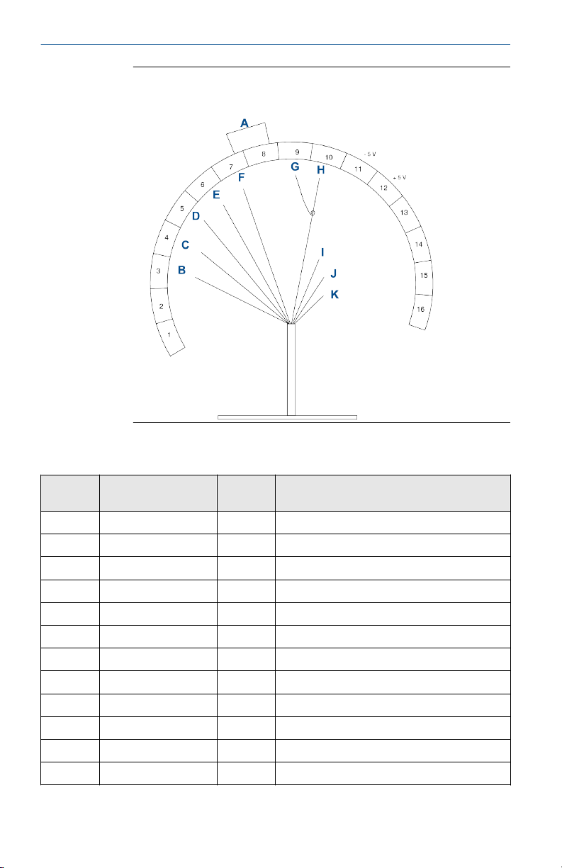
Figure 2-9: Rosemount RBI with Integral Cable Connection
Wiring Diagram for Rosemount 56, 1056, 1057, and 1066
Transmitters
14 Emerson.com/Rosemount
Page 15
September 2020 Quick Start Guide
Table 2-5: Rosemount RBI with Integral Cable Connection Wiring Diagram for
Rosemount 56, 1056, 1057, and 1066 Transmitters
Letter Wire color Terminal
number
A Green 1 Resistance temperature device (RTD) return
B Black 2 Resistance temperature device (RTD) sense
C Red 3 Resistance temperature device (RTD) in
D N/A 4 Ground
N/A N/A 5 +5 Vdc
N/A N/A 6 -5 Vdc
E Gray 7 pH shield
F Coaxial 8 pH in
G None 9 Reference shield
H White 10 Reference
I N/A 4 to 10 Jumper
Description
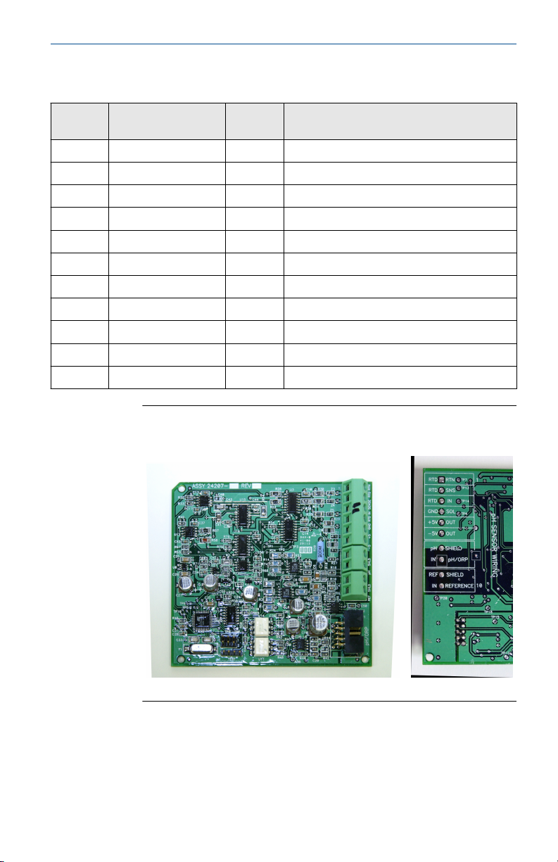
Figure 2-10: Example of Printed Circuit Board of the pH Card for
Rosemount 1056, 56, and 1057 Transmitters
Quick Start Guide 15
Page 16
Quick Start Guide September 2020
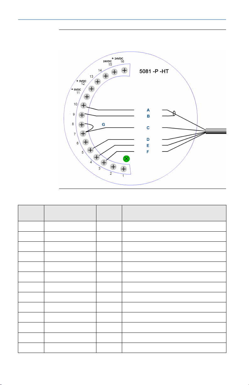
Figure 2-11: Rosemount RBI with Integral Cable Connection
Wiring Diagram for Rosemount 5081 Transmitters
Table 2-6: Rosemount RBI with Integral Cable Wiring to Rosemount 5081
Letter Wire color Terminal
number
N/A NA 1 N/A
N/A N/A 2 N/A
F Green 3 Resistance temperature device (RTD) return
E Black 4 Resistance temperature device (RTD) sense
D Red 5 Resistance temperature device (RTD) in
N/A N/A 6 Drain
C White 7 Reference
G Jumper 8 Solution ground
B Gray 9 Drain
A Coaxial 10 mV in
N/A N/A 11 -5 Vdc
N/A N/A 12 +5 Vdc
N/A N/A 13 Anode
16 Emerson.com/Rosemount
Description
Page 17
September 2020 Quick Start Guide
Table 2-6: Rosemount RBI with Integral Cable Wiring to Rosemount 5081
(continued)
Letter Wire color Terminal
number
N/A N/A 14 Cathode
N/A N/A 15 -24 Vdc
N/A N/A 16 +24 Vdc
Description
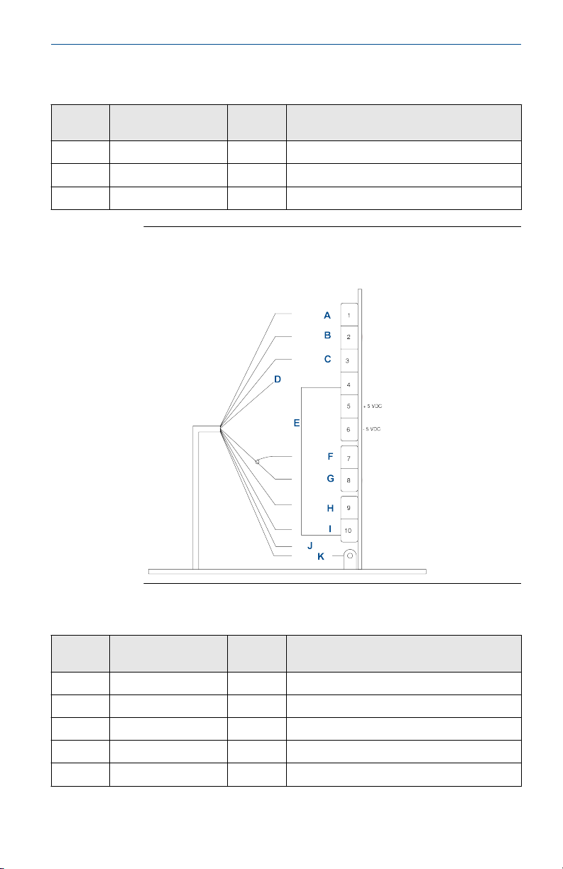
Figure 2-12: Rosemount RBI with Variopol Cable (24281-XX)
Wiring Diagram for Rosemount 56, 1056, and 1057 Transmitters
Table 2-7: Rosemount RBI with Variopol Cable (24281-xx) Wiring to Rosemount
56, 1056, and 1057 Transmitters
Letter Wire color Terminal
number
A White 1 Resistance temperature device (RTD) return
B White/red 2 Resistance temperature device (RTD) sense
C Red 3 Resistance temperature device (RTD) in
D Blue N/A No connect (cap)
E Jumper 4 to 10 Ground
Quick Start Guide 17
Description
Page 18
Quick Start Guide September 2020
Table 2-7: Rosemount RBI with Variopol Cable (24281-xx) Wiring to Rosemount
56, 1056, and 1057 Transmitters (continued)
Letter Wire color Terminal
number
N/A N/A 5 +5 Vdc
N/A N/A 6 -5 Vdc
F Clear 7 pH shield
G Orange 8 pH in
H White/gray 9 Reference shield
I Gray 10 Reference
J Clear ID N/A ID - no connect
K Green N/A N/A
Description
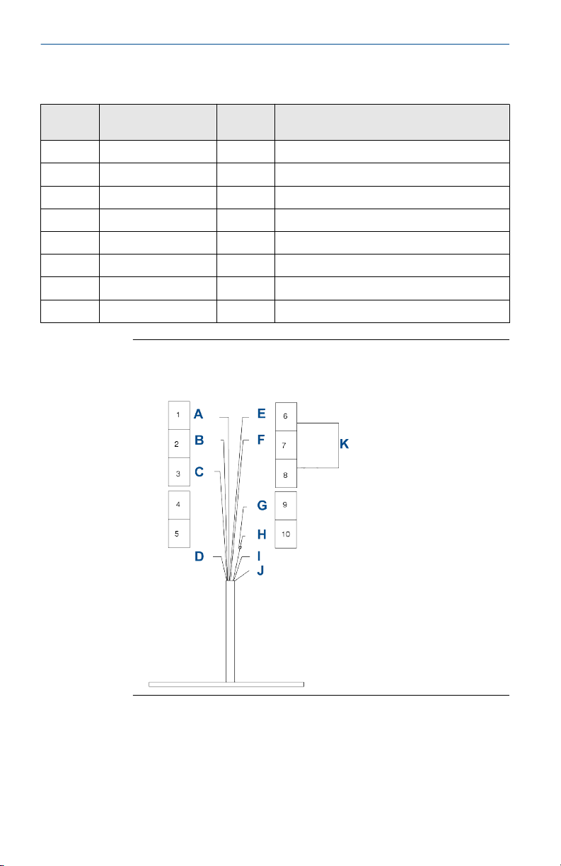
Figure 2-13: Rosemount RBI with Variopol Cable (24281-XX)
Wiring Diagram for Rosemount 1066 Transmitters
18 Emerson.com/Rosemount
Page 19

September 2020 Quick Start Guide
Table 2-8: Rosemount RBI with Variopol Cable (24281-xx) Wiring to Rosemount
1066 Transmitters
Letter Wire color Terminal
number
A White 1 Resistance temperature device (RTD) return
B White/red 2 Resistance temperature device (RTD) sense
C Red 3 Resistance temperature device (RTD) in
N/A N/A 4 + volts
N/A N/A 5 - volts
D Green N/A No connect (cap)
E Gray 6 Reference in
F White/gray 7 Reference shield
N/A N/A 8 Solution ground
K N/A 6 to 8 Jumper
G Clear 9 pH shield
H Clear 10 pH in
I N/A N/A No connect (cap)
J Blue N/A No connect (cap)
Description
Quick Start Guide 19
Page 20
Quick Start Guide September 2020
Figure 2-14: Rosemount RBI with Variopol Cable (24281-XX)
Wiring Diagram for Rosemount 5081 Transmitters
Table 2-9: Rosemount with Variopol Cable (24281-xx) Wiring to Rosemount 56,
1056, and 1057 Transmitters
Letter Wire color Terminal
number
N/A N/A 1 Reserved
N/A N/A 2 Reserved
B White 3 Resistance temperature device (RTD) return
C White/red 4 Resistance temperature device (RTD) sense
D Red 5 Resistance temperature device (RTD) in
E White/gray 6 Reference guard
F Gray 7 Reference in
A Jumper 8 Solution ground
G Clear 9 pH/ORP ground
H Orange 10 pH/ORP in
N/A N/A 11 -5 V
N/A N/A 12 +5 V
20 Emerson.com/Rosemount
Description
Page 21

September 2020 Quick Start Guide
Table 2-9: Rosemount with Variopol Cable (24281-xx) Wiring to Rosemount 56,
1056, and 1057 Transmitters (continued)
Letter Wire color Terminal
number
N/A N/A 13 Anode/reserved
N/A N/A 14 Cathode/reserved
N/A N/A 15 HART®/FOUNDATION™ Fieldbus (-)
N/A N/A 16 HART/FOUNDATION Fieldbus (+)
I Blue N/A No connect (cap)
J Green N/A Chassis screw
K Clear N/A ID - no connect (cap)
Description
3. After wiring the sensor leads, carefully take up the excess sensor
cables through the cable gland.
Quick Start Guide 21
Page 22

Quick Start Guide September 2020
3 Startup
Refer to the manual for your transmitter (Rosemount 56, 1056, 1057, 1066,
or 5081) for directions on operating the transmitter after it has been wired
to the sensor.
Procedure
1. Wire sensor(s) to the signal boards.
See Wire sensor to transmitter for wiring diagrams.
2. Once connections are secured and verified, apply power to the
transmitter.
WARNING
Risk of electrical shock
Electrical installation must be in accordance with the National
Electrical Code (ANSI/NFPA-70) and/or any other national or local
codes.
When the transmitter is initially powered up, Quick Start screens
appear.
3. Refer to the manual for your transmitter to complete the steps in the
Quick Start process.
22 Emerson.com/Rosemount
Page 23

September 2020 Quick Start Guide
4 Accessories
Part number Description
RB5104-0058E 8-in. (203,2 mm) titanium, Kynar®, EPDM, 547 retractable
RB5104-0078E 8-in. (203,2 mm) Hastelloy-C, Kynar, EPDM, 547 retractable
RB5104-0120E 20-in. (508 mm) titanium, Kynar, EPDM, 547 retractable
RB5104-0120V 20 in.(508 mm) titanium, Kynar, Viton®, 547 retractable
RB5104-0136E 36-in. (914,4 mm) titanium, Kynar, EPDM, 547 retractable
RB5104-0320E 20-in. (508 mm) Hastelloy-C, Kynar, EPDM, 547 retractable
RB5104-0336E 36-in. (914,4 mm) Hastelloy-C, Kynar, EPDM, 547 retractable
RB5104-0320K 20-in. (508 mm) Hastelloy-C, Kynar, Kalrez®, 547 retractable
23166-00 1-in. x 1-in. process connector, 316 stainless steel
23166-01 1-in. x 1-in. process connector, titanium
23240-00 1½-in. ball valve kit assembly, 316 stainless steel (does not
23765-00 1¼-in. ball valve kit assembly, 316 stainless steel (does not
24281-00 15-ft. (4,6 m) cable with mating VP8 connector
24281-01 25-ft. (7,6 m) cable with mating VP8 connector
24281-02 2.5-ft. (0,8 m) cable with mating VP8 connector
24281-05 4-ft. (1,2 m) cable with mating VP8 connector
24281-06 10-ft. (3 m) cable with mating VP8 connector
24281-07 20-ft. (6,1 m) cable with mating VP8 connector
24281-08 30-ft. (9,1 m) cable with mating VP8 connector
insertion sheath
insertion sheath
insertion sheath
insertion sheath
insertion sheath
insertion sheath
insertion sheath
insertion sheath
include process connector)
include process connector)
Quick Start Guide 23
Page 24

*00825-0100-3008*
EMERSON AUTOMATION SOLUTIONS
6021 Innovation Blvd.
Shakopee, MN 55379
+1 866 347 3427
+1 952 949 7001
RMTNA.RCCPO@Emerson.com
00825-0100-3008, Rev. AB
Quick Start Guide
September 2020
NORTH AMERICA
Emerson Automation Solutions
8200 Market Blvd
Chanhassen, MN 55317
Toll Free +1 800 999 9307
F +1 952 949 7001
RMTNA.RCCPO@Emerson.com
MIDDLE EAST AND AFRICA
Emerson Automation Solutions
Emerson FZE
Jebel Ali Free Zone
Dubai, United Arab Emirates, P.O. Box
17033
+971 4 811 8100
+971 4 886 5465
RMTNA.RCCPO@Emerson.com
LinkedIn.com/company/Emerson-
Automation-Solutions
Twitter.com/rosemount_news
Facebook.com/Rosemount
Youtube.com/RosemountMeasurement
EUROPE
Emerson Automation Solutions
Neuhofstrasse 19a PO Box 1046
CH-6340 Baar
Switzerland
+41 (0) 41 768 6111
+41 (0) 41 768 6300
RMTNA.RCCPO@Emerson.com
ASIA-PACIFIC
Emerson Automation Solutions
1 Pandan Crescent
Singapore 128461
Republic of Singapore
+65 6 777 8211
+65 6 777 0947
RMTNA.RCCPO@Emerson.com
©
2020 Emerson. All rights reserved.
The Emerson logo is a trademark and service
mark of Emerson Electric Co. Rosemount is a
mark of one of the Emerson family of companies.
All other marks are the property of their
respective owners.
 Loading...