

Page 1

RAMAN PROCESS ANALYZER
Instruction Bulletin IB-103-300 Rev 1.0
Page 2

Page 3

HIGHLIGHTS OF CHANGES
Effective May, 2001 Rev. 1.0
PAGE SUMMARY
Throughout Added information as needed to meet CE mark certification.
5-1 through 5-5 Added Analog Output section to manual.
Page 4

Page 5

ROSEMOUNT WARRANTY
The Raman Process Analyzer is designed for industrial applications. Treat with
care to avoid physical damage. THE WARRANTY DOES NOT COVER
DAMAGE FROM MISHANDLING.
Rosemount warrants that the equipment manufactured and sold by it will, upon
shipment, be free of defects in workmanship or material. Should any failure to conform to
this warranty become apparent during a period of one year after the date of shipment,
Rosemount shall, upon prompt written notice from the purchaser, correct such
nonconformity by repair or replacement, F.O.B. factory of the defective part or parts.
Correction in the manner provided above shall constitute a fulfillment of all liabilities of
Rosemount with respect to the quality of the equipment.
THE FOREGOING WARRANTY IS EXCLUSIVE AND IN LIEU OF
ALL OTHER WARRANTIES OF QUALITY WHETHER WRITTEN, ORAL,
OR IMPLIED (INCLUDING ANY WARRANTY OF MERCHANTABILITY
OF FITNESS FOR PURPOSE).
The remedy(ies) provided above shall be purchaser’s sole remedy(ies) for any failure
of Rosemount to comply with the warranty provisions, whether claims by the purchaser are
based in contract or in tort (including negligence).
Rosemount does not warrant equipment against normal deterioration due to
environment. Factors such as corrosive gases and solid particulates can be detrimental and
can create the need for repair or replacement as part of normal wear and tear during the
warranty period.
Equipment supplied by Rosemount Analytical Inc. but not manufactured by it will be
subject to the same warranty as is extended to Rosemount by the original manufacturer.
At the time of installation it is important that the required services are supplied to the
system. This will ensure, that should there be a delay between installation and full
commissioning that the analyzer being supplied with ac power will not be subjected to
component deterioration.
IB-103-300
i
Page 6
PURPOSE
The purpose of this manual is to provide a comprehensive understanding of the Raman Process Analyzer
components, functions, installation, and maintenance.
This manual is designed to provide information about the Raman Process Analyzer. We recommend that
you thoroughly familiarize yourself with the Description and Installation sections before installing your analyzer.
The description presents the basic principles of the analyzer along with its performance characteristics
and components. The remaining sections contain detailed procedures and information necessary to install and
service the analyzer.
Before contacting Rosemount concerning any questions, first consult this manual. It describes most
situations encountered in your equipment’s operation and details necessary action.
DEFINITIONS
The following definitions apply to WARNINGS, CAUTIONS, and NOTES found throughout this
publication.
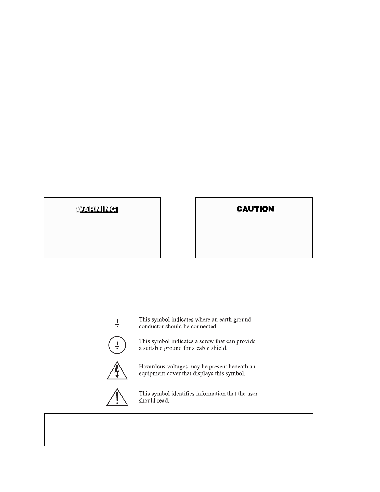
Highlights an operation or maintenance
procedure, practice, condition, statement,
etc. If not strictly observed, could result
in injury, death, or long-term health
hazards of personnel.
Highlights an essential operating procedure,
condition, or statement.
Highlights an operation or maintenance
procedure, practice, condition, statement,
etc. If not strictly observed, could result
in damage to or destruction of
equipment, or loss of effectiveness.
NOTE
NOTE TO USERS
The number in the lower right corner of each illustration in this publication is a manual illustration
number. It is not a part number, and is not related to the illustration in any technical manner.
IB-103-300
ii
Page 7
IMPORTANT
LASER SAFETY INSTRUCTIONS
The Raman Process Analyzer uses a Class IV Diode Laser with a maximum output of 1 Watt at a wavelength of 810 nm (invisible, near-infrared light). The light is transmitted through fiber optic cables to and
from the probe. The Raman Process Analyzer contains a Laser Safety Device that detects the return intensity of the laser light. If the return light diminishes below a certain level, the device reduces the laser
power to Class I. This safety feature reduces the chance of personnel injury from contact with the laser.
Take the following precautions when working around the Raman Process Analyzer:
Invisible laser light — avoid exposure to operating laser. A Class IV laser is used in
this analyzer. The laser has a maximum output of 1 Watt at a wavelength of
810 nm.
1. Only service this product if you have completed formal training in laser safety and
safe servicing techniques on this unit.
2. Never look at the probe tip when the probe is connected to the analyzer. Disconnect
the fiber optic cables before examining the probe.
3. Always clean the probe tip when removed from process. It may be possible for liquid droplets or particles to attach to the tip of the probe, allowing light “reflection”
to return to the Laser Safety Device. Use only appropriate material that will not
scratch or otherwise damage the probe tip.
4. Do not bring the probe tip in contact with any surfaces when removed from the process. Any “scattered” light returned by the probe may trigger the laser back to Class
IV.
5. All personnel working in the area of the laser must wear laser safety goggles (fullgoggle type with side shields). Goggles must have a minimum attenuation factor of
100,000 (optical density 5) for an 810 nm wavelength.
IB-103-300
iii
Page 8
IMPORTANT
SAFETY INSTRUCTIONS FOR THE WIRING AND
INSTALLATION OF THE LASER
The following safety instructions apply specifically
to all EU member states. They should be strictly
adhered to in order to assure compliance with the
Low Voltage Directive. Non-EU states should also
comply with the following unless superseded by
local or National Standards.
1. Adequate earth connections should be made to all earthing points, internal and external,
where provided.
2. After installation or troubleshooting, all safety covers and safety grounds must be
replaced. The integrity of all earth terminals must be maintained at all times.
3. Mains supply cords should comply with the requirements of IEC227 or IEC245.
4. All wiring shall be suitable for use in an ambient temperature of greater than 75°C.
5. All cable glands used should be of such internal dimensions as to provide adequate cable
anchorage.
6. To ensure safe operation of this equipment, connection to the mains supply should only
be made through a circuit breaker which will disconnect all circuits carrying conductors
during a fault situation. The circuit breaker may also include a mechanically operated
isolating switch. If not, then another means of disconnecting the equipment from the
supply must be provided and clearly marked as such. Circuit breakers or switches must
comply with a recognized standard such as IEC947 (properly grounded three wire source
of electrical power). All wiring must conform with any local standards.
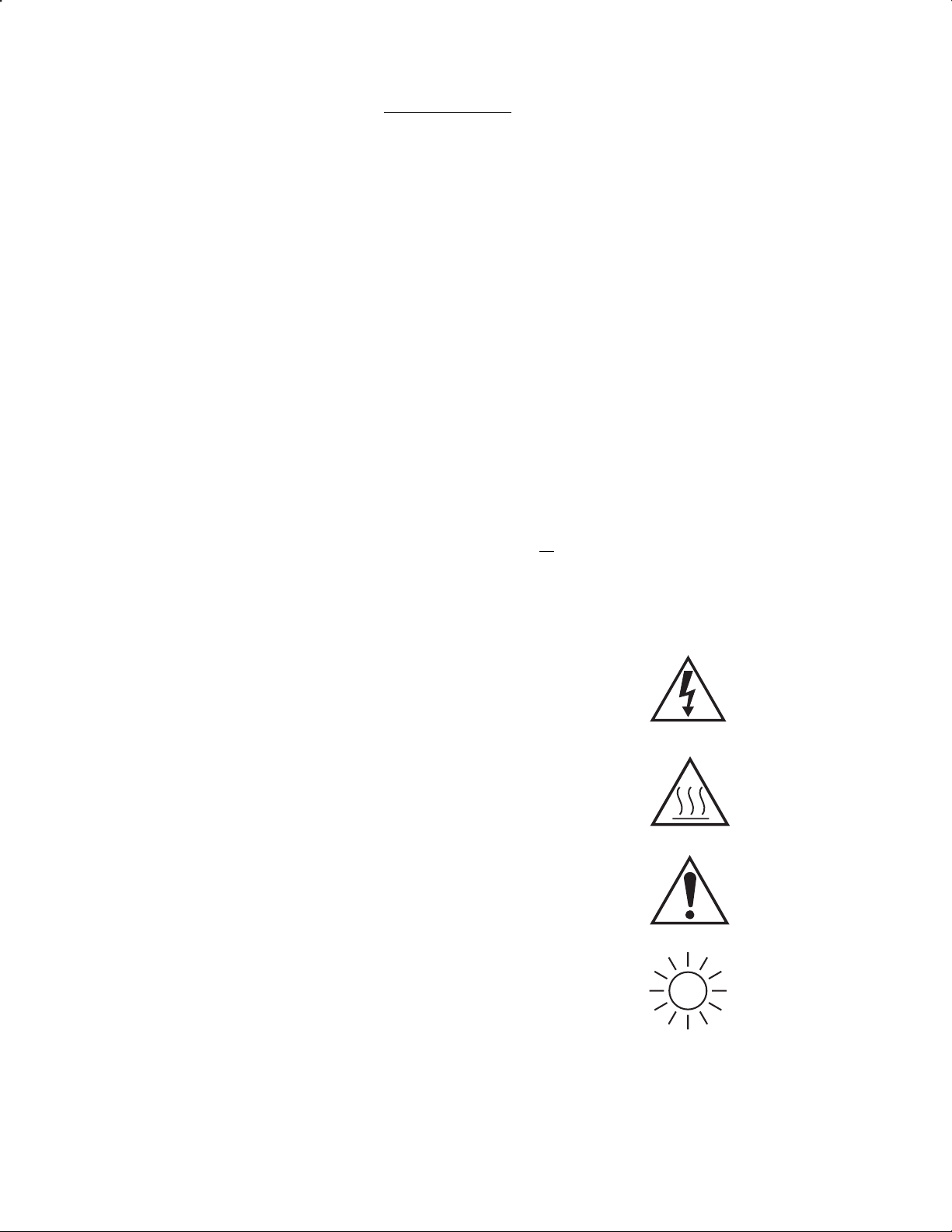
7. Warning - Electrical Shock Hazard. Where equipment or covers are
marked with the symbol to the right, hazardous voltages are likely to
be present beneath. These covers should only be removed when
power is removed from the equipment — and then only by trained
service personnel.
8. Caution - Hot Surface Hazard. Where equipment or covers are
marked with the symbol to the right, there is a danger from hot
surfaces beneath. These covers should only be removed by trained
service personnel when power is removed from the equipment.
Certain surfaces may remain hot to the touch.
9. Where equipment or covers are marked with the symbol to the
right, refer to the Operator Manual for instructions.
10. Warning - Laser Light Warning. Where equipment or covers
are marked with the symbol to the right, high powered laser
light is beneath. These covers should only be removed by
trained service personnel when power is removed from the
equipment.
11. All graphical symbols used in this product are from one or more of the following
standards: EN61010-1, IEC417, and ISO3864.
IB-103-300
iv
Page 9

ESSENTIAL INSTRUCTIONS
READ THIS PAGE BEFORE PROCEEDING
Rosemount Analytical designs, manufactures, and tests all its products to meet
many national and international standards. Because these instruments are sophisticated
technical products, you must properly install, use, and maintain them to ensure they
continue to operate within their normal specifications. The following instructions must
be adhered to and integrated into your safety program when installing, using, and
maintaining Rosemount Analytical products. Failure to follow the proper instructions
may cause any one of the following situations to occur: loss of life, personal injury,
property damage, damage to the instrument, and warranty invalidation.
• Read all instructions prior to installing, operating, and servicing the product. If this
Instruction Bulletin is not the correct manual, telephone 1-800-654-7768 and the required manual will be provided. Save this instruction manual for future reference.
• If you do not understand any of the instructions, contact your Rosemount represen-
tative for clarification. Refer to the technical support hotline on page ix.
• Follow all warnings, cautions, and instructions marked on and supplied with the
product.
• Inform and educate your personnel in the proper installation, operation, and mainte-
nance of the product.
!
• Install your equipment as specified in the installation instructions of the appropriate
Instruction Bulletin and per applicable local and national codes. Connect all products to the proper electrical and pressure sources.
• This product must only be used in the manner prescribed by Rosemount. To ensure
proper performance, use qualified personnel to install, operate, update, program,
and maintain this product.
• The environmental conditions in which this equipment is designed to operate is
within an ambient operating temperature of 32° to 122°F (0° to 50°C) at 20 to 100%
relative humidity.
• There are no operator-replaceable parts.When replacement parts are required, en-
sure that the qualified people use replacement parts specified by Rosemount. Unauthorized parts and procedures can affect the product’s performance and place the
safe operation of your process at risk. Look alike substitutions may result in fire,
electrical hazards, or improper operation.
• To prevent electrical shock and personal injury, ensure that all equipment doors are
closed and protective covers are in place. Only qualified persons are authorized to
open equipment doors and remove protective covers for equipment service or
maintenance.
IB-103-300
v
Page 10

WHAT YOU NEED TO KNOW
BEFORE INSTALLING AND WIRING A ROSEMOUNT
RAMAN PROCESS ANALYZER
1. What is the line voltage being supplied to the Raman Process Analyzer?
Write the line voltage here __________ .
2. Is the analyzer being controlled at the analyzer cabinet or by network connection?
3. Is the conduit set-up and all wiring for the analyzer run?
CAN YOU USE THE FOLLOWING
QUICK START GUIDE?
Use the Quick Start Guide if....
1. You are familiar with the Raman Process Analyzer installation requirements.
2. All wiring and conduit are in place for installation of the analyzer.
3. A configuration set exists for the process to be analyzed.
4. You are familiar with the SURE calibration procedures.
If you cannot use the Quick Start Guide, turn to Section II, Installation, in
this Instruction Bulletin.
IB-103-300
vi
Page 11

QUICK START GUIDE
RAMAN PROCESS ANALYZER
Before using the Quick Start Guide, please read “WHAT YOU
NEED TO KNOW BEFORE INSTALLING AND WIRING A
ROSEMOUNT RAMAN PROCESS ANALYZER” on the preceding page.
1. Mount the analyzer cabinet. Refer to Section II, paragraph 2-3.a.
2. Install the Raman probes. Refer to Section II, paragraph 0.
3. Install the fiber optic cable conduits. Refer to Section II, paragraph 0.
4. Connect the fiber optic cables. Refer to Section II, paragraph 1-1.a.
5. Connect the cooling air supply and filters to the analyzer cabinet. Refer to Section
II, paragraph 2-3.e.
6. Connect line voltage to the analyzer cabinet. Refer to Section II, paragraph 2-4.
7. Connect the network cable or computer peripherals to the analyzer cabinet. Refer
to Section II, paragraphs 0 and 2-6.
8. Turn power on to the analyzer cabinet.
9. If using a network connection to control the analyzer, use the NetSupport software
to enable communication with the analyzer. Refer to Section III, paragraph 3-1.
10. Use MAINCFG to select the desired configuration set. Refer to Section III, para-
graph 3-3.a.
11. Perform a dark scan and photometric calibration procedure. Refer to Section III,
paragraph 3-3.b.
12. Select the QUIT option to start the MAIN program and monitor the process.
IB-103-300
vii
Page 12

QUICK REFERENCE GUIDE
RAMAN PROCESS ANALYZER SOFTWARE
Select a configuration set
1. Close the MAIN program.
2. Start the MAINCFG program.
3. Select SYSTEM CONFIGURATION.
4. Select ENABLE A CONFIGURATION.
5. Select the configuration file to be used.
Calibrate the analyzer
1. Use the MAINCFG program and load the correct configuration set for the process
to be monitored.
2. Remove the probe from the process and ensure the probe is clean of any liquid or
foreign material.
3. Mount the probe in the SURE calibration kit.
4. Select PHOTOMETRIC CALIBRATION from the MAIN Setup Menu screen.
5. A prompt to verify that the probe is connected to the calibration kit is displayed.
Click the CONTINUE button.
6. Select the appropriate channel to be calibrated. Set the number of scans to 1 and
click CONTINUE.
7. The system auto-ranges and acquires the dark scan current, then displays the pho-
tometric curve. Make sure the curve is not saturated (have a flat region). If flat regions appear in the scan, back out the calibration kit two or three turns and press
RE-SAMPLE. Repeat the calibration kit adjustments and re-sampling until a
smooth photometric curve is measured.
8. Make sure the appropriate channel is selected and set the number of scans to 10.
Press RE-SAMPLE, then press CONTINUE.
9. Press STORE to save this scan for future use. The selected channel photometrics
are calibrated.
10. To calibrate the photometrics of another channel, repeat steps 1 through 9.
IB-103-300
viii
Page 13

Technical Support Hotline:
For assistance with technical problems, please call the Customer Support Center (CSC).
Phone: 1-800-433-6076
In addition to the CSC, you may also contact Emerson Process Management North
American Response Center (NARC). North American Response Center coordinates
Rosemount’s field service throughout the US and abroad.
Phone: 1-800-654-RSMT (1-800-654-7768)
Rosemount may also be reached via the Internet through e-mail and the World Wide
Web:
E-mail: GAS.CSC@emersonprocess.com
World Wide Web: www.processanalytic.com
Manufacturer’s Address
Rosemount Analytical Inc.
1201 N. Main Street
Orrville, Ohio 44667
IB-103-300
ix/x
Page 14

Page 15

TABLE OF CONTENTS
Section Page
Rosemount Warranty ................................................................................................................................... i
Section I. System Overview....................................................................................................................1-1
1-1. Scope Of Manual...........................................................................................................1-1
1-2. Components Checklist (Package Contents)...................................................................1-1
1-3. Functional Equipment Description................................................................................ 1-1
1-4. Equipment Specifications............................................................................................... 1-5
Section II. Installation .............................................................................................................................2-1
2-1. Overview ......................................................................................................................... 2-1
2-2. Typical Installation......................................................................................................... 2-1
2-3. Mechanical Installation ..................................................................................................2-2
2-4. Electrical Installation...................................................................................................... 2-5
2-5. Computer Network.........................................................................................................2-6
2-6. Computer Peripherals..................................................................................................... 2-6
2-7. Installation Inspections...................................................................................................2-7
Section III. Setup...................................................................................................................................... 3-1
3-1. Communication Software............................................................................................... 3-1
3-2. MAINCFG Program....................................................................................................... 3-3
3-3. Setup................................................................................................................................ 3-8
Section IV. Operation .............................................................................................................................. 4-1
4-1. Overview ......................................................................................................................... 4-1
4-2. Software Usage Conventions ........................................................................................4-1
4-3. MAIN Program Startup................................................................................................. 4-3
Section V. ANALOG OUTPUT .............................................................................................................5-1
5-1. Introduction ..................................................................................................................... 5-1
5-2. Analog Output Scaling Setup ....................................................................................... 5-1
5-3. Access The Scaling Setup Screen................................................................................5-1
5-4. Save (or Replace) Configuration..................................................................................5-3
5-5. How Scaling is Applied................................................................................................... 5-3
5-6. Analog Output Diagnostic Screen................................................................................ 5-4
5-7. Accessing the Diagnostic Screen..................................................................................5-4
5-8. Concentration Values ......................................................................................................5-5
5-9. Outputs ............................................................................................................................5-5
Section VI. Preventive Maintenance .....................................................................................................6-1
6-1. General ............................................................................................................................6-1
6-2. Cleaning ..........................................................................................................................6-1
Section VII. Troubleshooting.................................................................................................................. 7-1
7-1. General ............................................................................................................................7-1
7-2. Alarm Messages .............................................................................................................7-1
7-3. Troubleshooting ..............................................................................................................7-1
Section VIII. Service ................................................................................................................................8-1
8-1. General ............................................................................................................................8-1
8-2. Analyzer Component Replacement............................................................................... 8-1
8-3. Analyzer Calibration ......................................................................................................8-6
IB-103-300
xi/xiv
Page 16

TABLE OF CONTENTS (Continued)
Section Page
Section IX. Replacement Parts...............................................................................................................9-1
Section X. Returning Equipment to the Factory .............................................................................10-1
10-1. Returning Equipment....................................................................................................10-1
Glossary..........................................................................................................................................................1
Index............................................................................................................................................................... 1
LIST OF ILLUSTRATIONS
Figure Page
Figure 1-1. Typical Raman Process Analyzer System Package..............................................................1-1
Figure 1-2. Functional Equipment Diagram............................................................................................1-2
Figure 1-3. Analyzer Cabinet..................................................................................................................1-4
Figure 2-1. Typical Installation...............................................................................................................2-1
Figure 2-2. Analyzer Cabinet Installation...............................................................................................2-2
Figure 2-3. Raman Probe ........................................................................................................................2-2
Figure 2-4. Cable Pull Box .....................................................................................................................2-3
Figure 2-5. Cable to Pull Tape Connection.............................................................................................2-3
Figure 2-6. Probe Connections................................................................................................................2-4
Figure 2-7. Air Supply Hookup ..............................................................................................................2-5
Figure 2-8. Conduit Ports........................................................................................................................2-5
Figure 2-9. Input Power Terminal...........................................................................................................2-6
Figure 2-10. Computer Connections.........................................................................................................2-6
Figure 3-1. NETSUPPORT CONTROL Screen ...................................................................................3-1
Figure 3-2. KNOWN CLIENTS Screen ...............................................................................................3-1
Figure 3-3. MAINCFG Program Structure .............................................................................................3-2
Figure 3-4. SETUP MENUS Screen.....................................................................................................3-3
Figure 3-5. SYSTEM CONFIGURATION MENU Screen ................................................................3-3
Figure 3-6. SYSTEM CONFIGURATION Screen...............................................................................3-3
Figure 3-7. PLS SETUP Screen ............................................................................................................3-4
Figure 3-8. SYSTEM CONFIGURATION Screen...............................................................................3-4
Figure 3-9. CCD MAP Screen ...............................................................................................................3-5
Figure 3-10. CONFIGURE MODBUS Screen ........................................................................................3-5
Figure 3-11. SYSTEM CONFIGURATION MENU Screen .................................................................3-6
Figure 3-12. SETUP MENUS Screen......................................................................................................3-6
Figure 3-13. Calibration Message.............................................................................................................3-6
Figure 3-14. PHOTOMETRIC CALIBRATION Screen........................................................................3-7
Figure 3-15. DARK CURRENT CALIBRATION Screen ....................................................................3-8
Figure 4-1. MAIN Program Structure.....................................................................................................4-2
Figure 4-2. RAMAN PROCESS ANALYZER Screen........................................................................4-3
Figure 4-3. PASSWORD VERIFICATION Screen..............................................................................4-3
Figure 4-4. OPERATOR MENUS Screen ............................................................................................4-4
Figure 4-5. SETUP MENUS Screen.....................................................................................................4-4
Figure 4-6. ZERO CLIP OPTION Screen............................................................................................4-4
Figure 4-7. RAMAN ANALYZER DATALOG UTILITY Screen....................................................4-5
Figure 4-8. OPERATOR MENUS Screen ............................................................................................4-5
IB-103-300
xii
Page 17

LIST OF ILLUSTRATIONS (Continued)
Figure Page
Figure 4-9. GRAB SCAN MENUS Screen .........................................................................................4-5
Figure 4-10. GRAB SCAN Screen .......................................................................................................... 4-6
Figure 4-11. SAVE AS Screen ...............................................................................................................4-6
Figure 4-12. OPERATOR MENUS Screen.............................................................................................4-7
Figure 4-13. DIAGNOSTIC MENUS Screen..........................................................................................4-7
Figure 4-14. VIEW CALCULATIONS Screen.......................................................................................4-7
Figure 4-15. DIAGNOSTIC MENUS Screen..........................................................................................4-8
Figure 4-16. ANALOG INPUT MEASUREMENTS Screen.................................................................4-9
Figure 4-17. DIGITAL I/O STATE Screen............................................................................................ 4-9
Figure 4-18. SMART DIAGNOSTICS MENU Screen........................................................................ 4-10
Figure 4-19. ANALYZER SOFTWARE STATUS Screen.................................................................. 4-10
Figure 4-20. ANALYZER ALARMS STATUS Screen....................................................................... 4-11
Figure 4-21. PASSWORD VERIFICATION Screen ............................................................................4-12
Figure 4-22. TRENDS Screen ................................................................................................................4-12
Figure 4-23. SMART DIAGNOSTICS MENU Screen....................................................................... 4-13
Figure 4-24. PERFORMANCE MEASURES Screen ...........................................................................4-13
Figure 4-25. DARK CURRENT & PHOTOMETRIC CORRECTION Screen .................................4-14
Figure 4-26. CALIBRATION PATH & MODEL Screen ..................................................................4-14
Figure 4-27. DIAGNOSTICS MENUS Screen ....................................................................................4-15
Figure 4-28. OPERATOR MENUS Screen...........................................................................................4-15
Figure 4-29. SET SECURITY Screen ...................................................................................................4-16
Figure 4-30. SET PASSWORDS Screen...............................................................................................4-16
Figure 4-31 GRAB DARK SCAN Screen.......................................................................................... 4-16
Figure 4-32. ABOUT Screen .................................................................................................................. 4-16
Figure 5-1. RAMAN PROCESS ANALYZER Screen ........................................................................5-1
Figure 5-2. PASSWORD VERIFICATION Screen ..............................................................................5-2
Figure 5-3. OPERATOR MENUS Screen.............................................................................................5-2
Figure 5-4. SETUP MENUS Screen...................................................................................................... 5-2
Figure 5-5. ANALOG OUTPUT SCALING SETUP Screen ............................................................... 5-2
Figure 5-6. SAVE Prompt ......................................................................................................................5-3
Figure 5-7. DIAGNOSTIC MENUS Screen..........................................................................................5-4
Figure 5-8. ANALOG OUTPUT DIAGNOSTIC Screen ..................................................................... 5-4
Figure 7-1. Raman Troubleshooting Flowchart #1.................................................................................7-2
Figure 7-2. Raman Troubleshooting Flowchart #2.................................................................................7-3
Figure 7-3. Raman Troubleshooting Flowchart #3.................................................................................7-4
Figure 8-1. Fuse Locations .....................................................................................................................8-2
Figure 8-2. CCD Camera Thermocouple Removal.................................................................................8-2
Figure 8-3. Laser Cooling Fan Removal.................................................................................................8-3
Figure 8-4. Laser Removal .....................................................................................................................8-4
LIST OF TABLES
Table Page
Table 1-1. Raman Process Equipment Specifications (Analyzer)*...................................................... 1-5
Table 9-1. Replacement Parts for the Raman Process Analyzer ...........................................................9-1
IB-103-300
xiii/xiv
Page 18

Page 19

1
SECTION I. SYSTEM OVERVIEW
1-1. SCOPE OF MANUAL
This instruction bulletin covers installation, setup,
operation, troubleshooting, and maintenance of the
Raman Process Analyzer manufactured by Rosemount Analytical. The troubleshooting and service
procedures in this manual are limited to those that
can be performed by most equipment operators.
1-2. COMPONENTS CHECKLIST
(PACKAGE CONTENTS)
The Raman Process Analyzer system includes the
items listed in Figure 1-1. The SURE Calibration Kit
contains all the necessary components for quickly
calibrating the analyzer.
1-3. FUNCTIONAL EQUIPMENT DESCRIPTION
When properly configured, the analyzer detects and
measures the concentration of sample components
that inelastically scatter light. Access for the detection of the process components is accomplished with
one to four analyzer probes installed in or around the
process flow.
Functional components of the analyzer are shown in
the electronic diagram of Figure 1-2. The important
components of the diagram include the process
probes, the diode lasers, the laser safety device,
spectrograph, vortex cooler, CCD camera, and the
industrial computer. Brief descriptions of the analyzer component functions are provided in the following paragraphs.
1. Analyzer
2. Analyzer Test Records
3. Instruction Bulletin
4. Backup Software
5. SURE Calibration Kit
6. Oil Filter
7. Water Filter
8. In Situ Probe (1 per channel)
9. Fiber Optic Cables (3 per probe)
Figure 1-1. Typical Raman Process Analyzer System Package
IB-103-300
1-1
Page 20

PRESSURE
REGULATOR
AIR
SUPPLY
OIL
FILTER
VORTEX
COOLING
CHAMBER
AIR
VALV E
HOT
AIR
USER
INTERFACE
ANALYZER CABINET
INDUSTRIAL
COMPUTER
LASER
CONTROL
MODULE
WATER
FILTER
CONTROLLER
PROCESS PROBES
LASER
SAFETY
BOARD
DIAMOND
REFERENCE 1
FILTER
CCD
CAMERA
1
OPTIC
SPECTROGRAPH
DIODE
LASER 1
SPLITTER
OPTIC
FILTER
DIODE
LASER 2
DIAMOND
REFERENCE 2
CCD
CAMERA
HEAD
SPLITTER
SPLITTER
2
3
4
Figure 1-2. Functional Equipment Diagram
IB-103-300
1-2
SPLITTER
27320024
Page 21

The following are brief descriptions of analyzer component functions. A listing of components in the
analyzer cabinet is provided in Figure 1-3.
a. Diode Lasers and Probes. The analyzer uses
one or two diode lasers and up to four process
probes. Each diode laser generates a light beam.
The light beam is split in a 10/90 optic splitter.
Fiber optic cables transmit ten percent of the
beam to a diamond reference circuit and the remaining ninety percent to a 50/50 optic splitter.
A fiber optic cable from the diamond reference
transmits the reference beam to the spectrograph.
The ninety percent portion of the beam is evenly
split to provide excitation energy for two process
probes. Each beam is filtered at the probe to
eliminate stray radiation. The probe emits the
filtered laser beam into the process flow.
The process components inelastically scatter distinct wavelengths. Two return cables transmit
scattered light from the probe to the analyzer.
The unfiltered S cable transmits all scattered
light to the Laser Safety Device. The filtered R
cable transmits only a specific range of nearinfrared wavelengths to the spectrograph.
b. Laser Safety Device. To minimize operator
hazards, the laser safety device monitors the intensity of the scattered laser light from the process flow. If the safety device receives less than
an acceptably large part of the scattered light, it
reduces the laser power output from Class IV to
Class I.
The laser safety device continues to regulate the
output of the diode lasers at pulsed Class I power
levels until the device detects an acceptable
amount of scattered light from the process.
Low light scatter may indicate a broken fiber optic cable, a bad cable connection, or removal of
the probe from the process. Refer to the “Laser
Safety Instructions” in the front of this manual
for more information.
c. Vortex Cooler. The vortex cooler helps control
the temperature of the CCD (charge coupled device) camera and the cabinet interior. The main
function of the vortex cooler is to maintain the
ambient temperature near the camera at 30°C so
that the internal CCD chip temperature will remain at –30°C.
Incoming instrument air is dried, filtered, and
routed through a temperature-controlled air valve
to the vortex cooler. The vortex effect separates
the forced air into warm and cold air flows. The
chilled air is routed to the CCD camera.
As the cabinet air gets warmer, the air valve
opens a larger flow of forced air to the vortex
chamber, providing more cooling air to the camera. As the cabinet air cools, a proportional air
valve partly closes to slow the flow of cooling
air.
d. Spectrograph and CCD Camera. Filtered light
from the diamond reference and the R probe is
transmitted by fiber optic cable to the spectrograph. The spectrograph separates incoming light
into distinct wavelengths. Each wavelength of
light is sent to the CCD camera head where the
spectral image is decoded and electronically transferred to the CCD camera controller. The controller processes the spectral image into numerical
data. The data is sent to the industrial computer for
interpretation and display.
e. Industrial Computer. The industrial computer
converts data points into light intensity with respect to frequency. The histogram of each predicted component is displayed on the CRT. The
spectra are processed by the prediction’s algorithm in accordance with the calibration file.
Each application requires its own calibration file.
The output data is stored for further analysis.
f. User Interface. An interface device is required
to set up and operate the analyzer using the
MAIN and MAINCFG software programs. The
user interface device can be a remote computer
connected through a network modem, Ethernet,
RF antenna and laptop computer, or a monitor,
keyboard, and mouse connected at the analyzer
cabinet.
g. Analyzer Outputs. The available analyzer out-
puts are MODBUS and/or analog, 4 to 20 mA.
h. SURE Calibration Kit. The SURE calibration
kit is a light proof housing that secures the probe
tip above a fluorescent glass. The kit uses no
external light source or power source. When the
fluorescent glass and probe are properly assembled in the light-proof housing, the analyzer can
be calibrated using the MAINCFG software program.
IB-103-300
1-3
Page 22

1. Hoffman Enclosure 10. Temperature Controller
2. Computer Power Supply 11. Enclosure Backplate
3. Computer 12. CCD Camera Controller
4. Disk Drives 13. Spectrograph Assembly
5. Optics Assembly Tray 14. Laser Pedestal Assembly
6. CCD Camera 15. Laser Safety Device
7. CCD Camera Hood 16. Proportional Air Valve
8. Termination Board 17. Raman Power Supply
9. Peripheral Device Connector 18. Vortex Cooler Assembly
Figure 1-3. Analyzer Cabinet
IB-103-300
1-4
Page 23

1-4. EQUIPMENT SPECIFICATIONS
Table 1-1. Raman Process Equipment Specifications (Analyzer)*
Spectral Range ........................................................................................................... 500 cm
-1
to 2000 cm-1 Raman Shift
Spectral Resolution .................................................................................................................................................. ∼2 nm
Typical Error ...................................................................................... Less than 1% of full-scale, application dependent
Operating Temperature ............................................................................................................. 32° to 122°F (0° to 50°C)
Storage Temperature ................................................................................................................ 32° to 122°F (0° to 50°C)
Relative Humidity .......................................................................................................................................... 20 to 100%
Warm-up Time ................................................................................................................................................ 60 minutes
Input Power ........................................................................................................... 115 VAC, 60 Hz or 230 VAC, 50 Hz
Power Rating ......................................................................................................................................... 250 VA (250 W)
Electrical Classification ................................................................... General Purpose or Class I, Div II, Type “Z” Purge
Environmental Classification .......................................................................................................................... NEMA-4X
Dimensions (H x W x D) .................................................................................. 48 x 24 x 12 in. (1219 x 610 x 305 mm)
Weight ...................................................................................................................................................... 165 lbs (75 kg)
Certification ........................................................................................................................................................ CE Mark
*Probe specifications may vary from probe to probe. Refer to the material supplied with probe for specifications.
1-5. CERTIFICATIONS
Emerson Process Management has satisfied all obligations coming from the European legislation to harmonize the product requirements in Europe.
IB-103-300
1-5/1-6
Page 24

Page 25

2
SECTION II. INSTALLATION
2-2. TYPICAL INSTALLATION
Before starting to install this equipment,
read the “Safety instructions for the
wiring and installation of the laser” at
the front of this Instruction Bulletin.
Failure to follow the safety instructions
could result in serious injury, death, or
substantial property damage.
2-1. OVERVIEW
This section covers installation of the Rosemount
Raman Process Analyzer. Included are a typical installation, common requirements, what you need to
have on hand to start an installation, and the mechanical and electrical installation instructions. An
authorized Rosemount service representative must
complete the analyzer installation. You must complete the mechanical installation before calling the
service representative for final check-out and installation commissioning.
A typical system installation is shown in Figure 2-1.
When properly installed, the analyzer cabinet is securely mounted to a wall in the process control area.
The cabinet should not be mounted in the path of direct sunlight.
Process probes are installed in the process flow (usually a sampling flow). Up to four process probes may
be installed for each analyzer. The installed probes
should be adequately shielded from accidental impact, rainfall, and direct sunlight. Ready access for
probe removal, cleaning, and replacement is recommended.
Fiber optic cable lengths are per customer specification. Make sure the correct cables are selected for
each run. One inch or larger diameter conduits or cable troughs are recommended for shielding the fiber
optic cables. Pull boxes are needed when successive
cable bend angles exceed 180 degrees. Conduit ends
should point down to protect against water accumulation. Sharp conduit edges must be avoided and the
cables should be lubricated before pulling.
Figure 2-1. Typical Installation
IB-103-300
2-1
Page 26
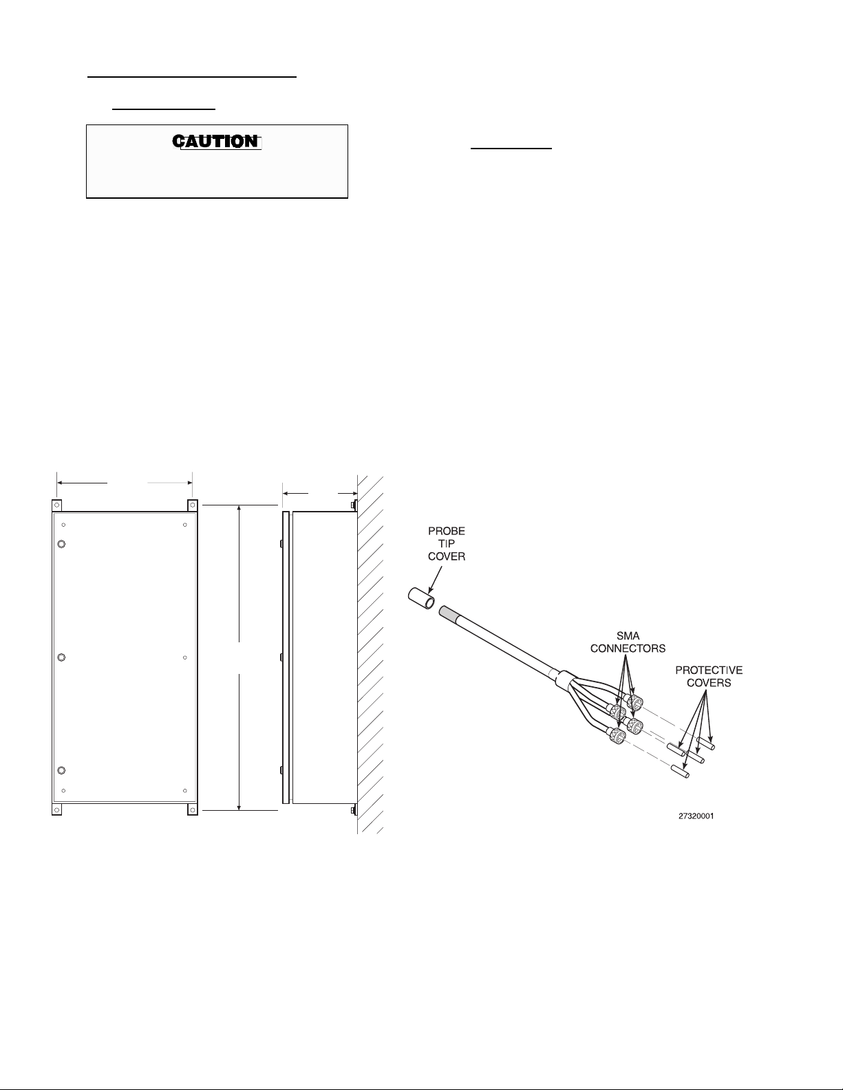
2-3. MECHANICAL INSTALLATION
a. Analyzer Cabinet.
Lift the cabinet with the upper brackets. Avoid
contact with the vortex cooler. Position and securely mount the cabinet using appropriate
screws and flat washers.
b. Raman Probe.
Never rest the cabinet standing up.
Damage to conduit fittings can occur.
The analyzer is housed in a NEMA-4X cabinet.
The NEMA-4X cabinet is suitable for wall
mounting in a Class I, Division II environment
when equipped with an ISA Type Z-Purge.
When lifting, the cabinet door must be closed
and latched. Make sure the mounting brackets
are installed and tight.
The analyzer cabinet weighs approximately 165
lbs (75 kg). Analyzer cabinet mounting dimensions are provided in Figure 2-2. Mark the position for cabinet hanger mounting on center with
wall studs or a securely mounted plywood backplate.
24.0
(609.6)
12.0
(304.8)
Each analyzer system includes up to four process
probes designed for mounting in a flow line or
tank. Install each process probe according to the
following instructions:
1.
Remove the protective covers from the
probe tip, Figure 2-3.
2. Install a bored through compression fitting
of compatible metallurgy in the process
line, tee, or process tank wall.
3.
Insert the probe to the desired depth in the
compression fitting.
4. If compatible with the process, apply a suit-
able sealant around the seal diameter of the
probe.
5. Tighten the compression fitting to secure
the probe. Do not over-tighten the fitting.
48.0
(1219.2)
NOTE:
DIMENSIONS ARE IN INCHES WITH
MILLIMETERS IN PARENTHESIS.
Figure 2-2. Analyzer Cabinet Installation
27320025
IB-103-300
Figure 2-3. Raman Probe
2-2
Page 27
ENDPLATE
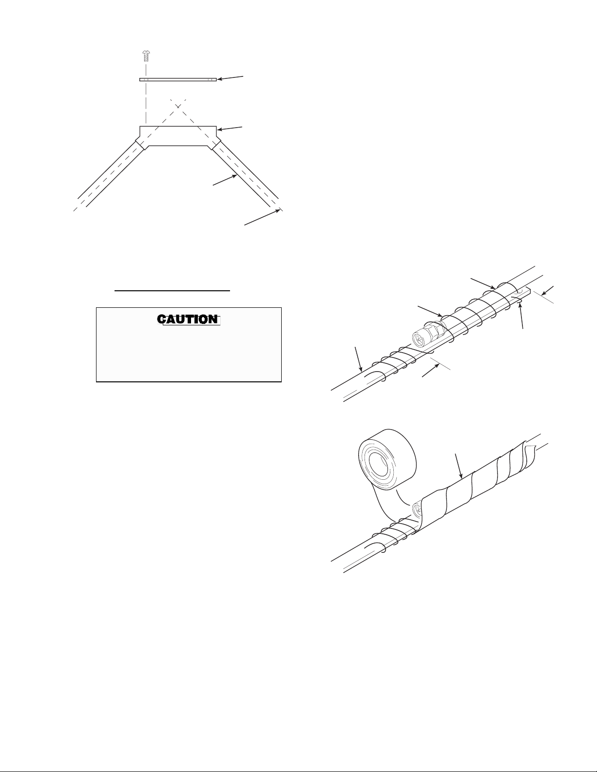
4. Overlay 3 ft (91.4 cm) of the fiber optic ca-
ble onto the pull tape and wrap with nylon
string to hold in place. Wrap and tape the
fiber optic cable to the pull tape as shown in
Figure 2-5.
CABLE PULL
BOX (90 TURN
CONDUIT
FIBER OPTIC
CABLE
Figure 2-4. Cable Pull Box
c. Fiber Optic Cable Conduits.
Fiber optic cables are precision optics
devices. Careless handling or installation of a fiber optic cable can result in
permanent cable damage.
1.
Install a 3/4 in. (19 mm) diameter minimum
conduit from the analyzer cabinet to each
process probe. The minimum radius for all
conduit bends is 10 in. (254 mm). For fiber
optic cable runs, it is not required to connect the conduit to the analyzer cabinet.
o
FITTING)
27320060
NYLON STRING
(WRAP TIGHTLY)
PULL TAPE
5.
Carefully pull the cable through the conduit; pull enough cable to allow for cable
slack when connecting at the analyzer cabinet or probe.
6.
When using cable pull boxes, turn the
coiled cable over. Feed the pull tape to the
opposite side of the pull box. Wrap and tape
the cable to the pull tape and pull the free
end through the next section of conduit.
Repeat the cable pulling instructions as
needed to install all fiber optic cables.
FIBER OPTIC
CABLE
FEED STRING
THROUGH PULL
TAPE EYELET
3FT
(91.4 CM)
WRAP WITH
ELECTRICAL
TAPE
2.
Install a cable pull box following a series of
conduit bends totaling 180 degrees. A 90
degree turn fitting (Figure 2-4) is recommended for use as a cable pull box.
3.
When using pull boxes, coil the fiber optic
cable into a figure eight below the pull box.
Feed a cable pull tape from one conduit end
to the pull box.
27320031
Figure 2-5. Cable to Pull Tape Connection
IB-103-300
2-3
Page 28

d. Connecting Fiber Optic Cables.
Each process probe has four SMA connectors.
The probe connectors are marked “S” for the laser safety, “L” for laser excitation light, and “R”
for Raman light collection. The L and R connectors have mating, in-line optic filters. The
unmarked connector is a spare S or R connector.
Install the Raman probes according to the following instructions:
1.
Remove the protective caps from the S, L,
and R probe connectors (Figure 2-6).
Carefully handle fiber optic cables.
Avoid bending, pulling, or compressing
the cables. Excess stress on the cables or
connectors can cause permanent cable
damage.
The Raman probe is a delicate precision
optics device. Careless handling or installation can result in permanent probe
damage.
Figure 2-6. Probe Connections
IB-103-300
2-4
Page 29

2. Remove a protective cap from one probe
terminal. Tilt the mating optic filter or cable connector and carefully align the fiber
optic filament with the mating filter or connector orifice. Level both connectors, insert the filament, and install the connector
finger tight.
2-4. ELECTRICAL INSTALLATION
Use the following procedures to supply electrical
power to the analyzer. Input power to the module
can be either 115 VAC, 60 Hz or 230 VAC, 50 Hz,
single phase. A 15 amp, 115 VAC or 220 VAC
electrical circuit breaker is required.
NOTE
Save the protective caps and use them
whenever the fiber optic cables are disconnected. For ready access, Rosemount recommends that you store the protective caps
in a plastic bag taped to the inside of the
analyzer cabinet door.
3. Repeat step 2 for each probe connector and
mating filter and/or cable connector.
4. Using a procedure similar to step 2, care-
fully connect the fiber optic cables to their
mating terminals at the analyzer cabinet.
e. Air Supply Connection. The analyzer uses a
vortex cooler system to maintain the analyzer
cabinet temperature. Connect the supplied water
and oil filters to the analyzer cabinet as shown in
Figure 2-7.
Rosemount recommends mounting a pressure
gage after the filters to monitor filter performance.
Connect the air supply and air pressure regulator
to the water filter. The instrument air supply
must be dry, filtered air at 60 psi (414 kPa)
minimum, developing 15 SCFM, minimum.
Rosemount recommends installing an ON/OFF
switch outside the analyzer cabinet.
Install all protective equipment covers
and safety ground leads after installation. Failure to install covers and
ground leads could result in serious injury or death.
a. Input Voltage Selector. The input voltage se-
lection is configured per customer request (115
or 230 VAC). If it becomes necessary to change
the input voltage, contact an authorized Rosemount Service Representative.
b. Electrical Wiring and Conduits.
NOTE
It may be necessary to enlarge conduit ports
to install the conduits.
All electrical wiring and conduits must conform
to local codes. The minimum requirement for
the electrical supply line is a 3-wire, 10 amp, 220
VAC conductor. Refer to Figure 2-8 for the location of the conduit ports.
AIR
SUPPLY
60 PSI
(414 kPa)
PRESSURE
REGULATOR
WATER
FILTER
PRESSURE
GAGE
OIL
FILTER
Figure 2-7. Air Supply Hookup
ANALYZER
CABINET
27320026
Figure 2-8. Conduit Ports
IB-103-300
2-5
Page 30

c. Cabinet Power.
Disconnect and lock out power source
before working on electrical components. Failure to lock out power may result in severe injury or death.
Lock out the cabinet power source at the main disconnect. Connect cabinet electrical power at the input power terminal (Figure 2-9). A green and yellow
protective earth ground conductor equal in size to the
in-coming main supply conductors must be connected at the ground terminal.
NOTE
All through cables and wiring should be
routed through the conduit ports on the
bottom of the cabinet.
To ensure safe operation, connection to
the main electrical power supply must
be made through a 115 or 220 VAC, 15
amp circuit breaker that will disconnect
all current-carrying conductors during a
fault situation. The power circuit should
also include a mechanically operated
isolating switch or other means of disconnecting the supply near the analyzer
cabinet. Circuit breakers and switches
must comply with recognized standards.
2-5. COMPUTER NETWORK
If using the network function of the analyzer, connect
an appropriate networking cable to the computer modem terminal shown in Figure 2-10.
2-6. COMPUTER PERIPHERALS
A monitor, keyboard, and mouse may be connected
to the analyzer computer. Remove the computer terminal cover and connect the peripherals to the terminals shown in Figure 2-10.
Figure 2-9. Input Power Terminal
Figure 2-10. Computer Connections
IB-103-300
2-6
Page 31

2-7. INSTALLATION INSPECTIONS
Perform the following equipment installation checks
in the order provided.
Install all protective equipment covers
and safety ground leads after installation. Failure to install covers and
ground leads could result in serious injury or death.
a. Mechanical Checks.
1. Verify that the analyzer cabinet is securely
mounted out of the path of direct sunlight.
2. Verify that all the fiber optic cables are
connected to mating terminals on the analyzer termination board. Ensure that all fiber optic cable connections are finger-tight.
3. Verify the Raman probes are properly in-
stalled in the process stream. Verify that all
probe shields are in place.
4. Verify that the fiber optic cables and optic
filters are connected to mating terminals on
the probe. Ensure that all fiber optic cable
connections are finger-tight.
b. Electrical Checks.
1.
Verify that analyzer input power is properly
connected per Figure 2-9.
2. Open the analyzer cabinet and verify that
the computer POWER ON/OFF switch is in
the ON position.
3.
Verify that the CCD camera controller
POWER ON/OFF switch is in the ON position and close the analyzer cabinet.
4.
If using the remote networking, ensure the
network cables are attached to the analyzer
per Figure 2-10.
IB-103-300
2-7/2-8
Page 32

Page 33

3-1. COMMUNICATION SOFTWARE
When provided, the NetSupport Local Control program allows remote personal computers to communicate with the analyzer through a RF wireless network.
The NetSupport software must be started each time
the remote computer is turned on. If needed, refer to
the software manual for more information. To initiate network access to the analyzer:
a. Select NETSUPPORT LOCAL CONTROL
from the Windows™ START menu. The
NETSUPPORT CONTROL screen (Figure 3-1)
is displayed.
b. From the NETSUPPORT CONTROL screen,
click on the menu CLIENTS and select CONNECT/DISCONNECT from the menu items.
The KNOWN CLIENTS screen (Figure 3-2) is
displayed.
c. In the KNOWN CLIENTS screen, click the
analyzer you wish to control and click the CONNECT button. The program will prompt you
when the connection is made.
3
SECTION III. SETUP
27320033
Figure 3-2. KNOWN CLIENTS Screen
d. After the program prompts that the connection is
made, click the CLOSE button. You will be returned to the NETSUPPORT CONTROL
screen. From the NETSUPPORT CONTROL
screen, click on the menu SELECTED CLIENTS menu and select CONTROL from the
menu items.
e. The program will display a message informing
you how to switch from the client computer to
the local computer. Click on the OK button.
27320032
Figure 3-1. NETSUPPORT CONTROL Screen
f. The local computer will now display the RA-
MAN PROCESS ANALYZER screen of the
MAIN program for the analyzer selected above.
Analyzers supplied with an Ethernet connection are
equipped with pcANYWHERE software. The
pcANYWHERE software provides TCP/IP protocol and allows a personal computer (PC) to commu-
nicate with multiple Raman Analyzers along a
network. When provided, pc ANYWHERE also
supports modem communication.
IB-103-300
3-1
Page 34

Figure 3-3. MAINCFG Program Structure
IB-103-300
3-2
Page 35

27320013
Figure 3-4. SETUP MENUS Screen
Figure 3-5. SYSTEM CONFIGURATION
MENU Screen
27320014
3-2. MAINCFG PROGRAM
This program is used for setting up and calibrating
the Analyzer.
a. Starting the MAINCFG Program. Before
starting the MAINCFG program, close the
MAIN program, if running. Select FILE ⇒
EXIT from the MAIN file menu. To start the
MAINCFG program, select MAINCFG from the
Windows START menu. Figure 3-3 shows the
MAINCFG program structure.
b. SETUP MENUS. The SETUP MENUS screen
(Figure 3-4) displays when the program starts.
The selections following are available from the
SETUP MENUS screen:
1.
SYSTEM CONFIGURATION. Clicking
on the SYSTEM CONFIGURATION button displays the SYSTEM CONFIGURATION MENU screen shown in Figure 3-5.
NOTE
(a) CHANGE AN EXISTING CON-
FIGURATION. Selecting this button
allows you to specify new settings for
a configuration file used to process
raw data. The program will prompt
you for the configuration file to be
modified. When the file is selected,
the SYSTEM CONFIGURATION
screen (Figure 3-6) displays the following menu selections:
1
CONFIGURE PLS. Clicking this
button prompts you to select a
calibration file to use in the configuration. When a calibration
file is selected, the PLS SETUP
screen (Figure 3-7) displays.
When changing a configuration file, keep in
mind that the file will be overwritten and
the previous configuration will be lost.
27320015
Figure 3-6. SYSTEM CONFIGURATION
Screen
IB-103-300
3-3
Page 36

Figure 3-7. PLS SETUP Screen
27320016
The PLS SETUP screen allows
you to enable or disable the PLS
predictions used to display the
histogram on the RAMAN PROCESS ANALYZER screen.
Click on the ACCEPT button to
accept the new calibration file.
Click on the QUIT button to exit
without changing the calibration
file.
2 CONFIGURE STRIPS. Clicking
on this button displays the CCD
MAP screen (Figure 3-9). This
screen allows you to select the regions of interest (ROI) on the
CCD camera array. Use the
GRAB AN IMAGE button to
acquire an image. Click on and
drag the lines on the image map to
define the diamond reference
channel and sample channel
ROIs. Green lines define the ROI
for the diamond reference channel. Black lines define the ROI
for the sample channel. Click on
the APPLY STRIPS button to
save the new strip configuration.
Click on the QUIT button to exit
the CCD MAP screen.
27320015
Figure 3-8. SYSTEM CONFIGURATION
Screen
IB-103-300
3-4
Page 37

Figure 3-9. CCD MAP Screen
27320018
Figure 3-10. CONFIGURE MODBUS Screen
3
FACTORY PARAMETERS.
This screen is for use by authorized Rosemount Service Representatives only.
27320017
4
CONFIGURE MODBUS.
Click on this button to display the
CONFIGURE MODBUS screen
in Figure 3-10. This screen allows you to configure the RS-485
serial port parameters. This
screen is typically used by
authorized Rosemount Service
Representatives only.
The ACCEPT button saves the
displayed parameters and returns
you to the SYSTEM CONFIGURATION screen.
The QUIT button will ignore parameter changes and return you to
the SYSTEM CONFIGURATION screen.
5 ACCEPT. Clicking on the AC-
CEPT button saves the new system configuration set and returns
you to the SYSTEM CONFIGURATION MENU screen.
IB-103-300
3-5
Page 38

6 QUIT. Clicking on the QUIT
button will discard the configuration changes made and will return
you to the SYSTEM CONFIGURATION MENU screen.
(b) CREATE A NEW CONFIGURA-
TION SET. This button (Figure
3-11) allows you to create a new configuration set using the same configuration menus as changing a
configuration set. The program will
prompt you for the file name before
the SYSTEM CONFIGURATION
screen displays.
(c) ENABLE A CONFIGURATION.
This button allows you to select a configuration file. The program will
prompt you for the configuration file
to load.
27320013
Figure 3-12. SETUP MENUS Screen
2.
X-AXIS CALIBRATION. The X-AXIS
CALIBRATION option (Figure 3-12)
should be used by authorized Rosemount
Service Representatives only.
(d) QUIT. Clicking on the QUIT button
returns you to the MAIN screen.
27320014
Figure 3-11. SYSTEM CONFIGURATION
MENU Screen
3. PHOTOMETRIC CALIBRATION.
Clicking this button displays a configuration message (Figure 3-13). When the
probe is mounted in the SURE calibration
kit, click the CONTINUE button.
If the probe is not mounted in the SURE
calibration kit, click the QUIT button to
return to the SETUP MENUS screen.
ENSURE THAT THE FLUORESCENT MATERIAL
IS ATTACHED TO THE END OF THE PROBE FOR
THE CHANNEL TO BE CALIBRATED
27320057
Figure 3-13. Calibration Message
IB-103-300
3-6
Page 39

Figure 3-14. PHOTOMETRIC CALIBRATION Screen
27320058
The PHOTOMETRIC CALIBRATION
screen (Figure 3-14) is used during the
analyzer calibration procedure outlined in
paragraph 3-3.b of this section. When the
number of scans to average has been entered, click the continue button. The analyzer performs a series of scans and
averages the scans to display a calibration
spectrum. When the spectrum is displayed,
the following buttons appear on the bottom
of the screen:
(a) RE-SAMPLE. Clicking the RE-
SAMPLE button starts the calibration
process over. The new averaged
spectrum will display.
(b) STORE. Clicking the STORE button
will save the calibration spectrum for
use in the configuration set as the
photometric calculation spectrum.
(c) QUIT. Clicking the QUIT button will
exit without saving the spectrum and
return you to the SETUP MENUS
screen.
4. DARK CURRENT CALIBRATION.
Clicking on the DARK CURRENT
CALIBRATION button displays the DARK
CURRENT CALIBRATION screen
(Figure 3-15). This screen allows you to
capture and save a dark scan used to cancel
out the dark current background “noise”
captured by the camera. To grab a dark
scan, click on the RE-SAMPLE button.
The scan will display on the CRT. To save
the dark scan, click on the STORE button.
To exit the DARK CURRENT CALIBRATION screen, click on the QUIT
button.
5. ABOUT . Clicking the ABOUT button
displays the program information, such as
version and date.
6. END. Clicking on the END button exits the
MAINCFG program.
IB-103-300
3-7
Page 40

3-3. SETUP
The following procedures are for setup and calibration of the analyzer. If you are inexperienced, or do
not understand the procedures, contact an authorized
Rosemount service representative for help.
The analyzer must be calibrated after any of the following occurs:
process. After selecting a configuration set, the
analyzer must be calibrated according to step
3-3.b.
An existing configuration set can be modified
using the MAINCFG program. See CHANGE
AN EXISTING CONFIGURATION on page
3-3 for more information on modifying an existing configuration set.
• Replacement of fiber optic cable(s).
• Replacement of Diode Laser.
• Adjustment of laser power.
•
Process or configuration set change.
a. Select A Configuration Set. A configuration
set must be selected prior to monitoring a
A new configuration set may be created using the
MAINCFG program. See CREATE A NEW
CONFIGURATION SET on page 3-6 for more
information on creating a new configuration set.
After modifying or creating a new configuration
set, the set must then be enabled. See ENABLE
A CONFIGURATION on page 3-6 for more information on enabling a configuration set.
Figure 3-15. DARK CURRENT CALIBRATION Screen
IB-103-300
3-8
27320019
Page 41

b. Calibration. Calibrate the analyzer according to
the following procedure:
click the CONTINUE button. The analyzer
begins the calibration process.
1. Verify that the correct configuration set is
loaded for the process to be monitored.
(a) Exit the MAIN program and start the
screen.
(b) Type the MAINCFG program.
(c) Select the SYSTEM CONFIGURA-
TION button from the SETUP
MENUS screen.
(d) Select ENABLE A CONFIGURA-
TION from the SYSTEM CONFIGURATION MENU screen and
enter the name of the file you will be
using to monitor the process.
2. Remove the probe from the process stream.
Clean all liquid and foreign material from
the probe.
3.
Carefully place the probe into the SURE
calibration block and secure the probe.
4. From the SETUP MENUS screen, select
PHOTOMETRIC CALIBRATION. The
calibration message will display. If the
probe is mounted in the SURE calibration
kit, click the CONTINUE button. Otherwise click the QUIT button.
5.
Using the PHOTOMETRIC CALIBRATION screen as described on page 3-7, set
the number of scans to average to 1 and
6. The analyzer will display a graph of the
dark scan current followed by a display of
the photometric curve.
7. Inspect the photometric curve for a quick
rise or fall followed by a flat region. A flat
region indicates that the detector is saturated; the probe must be backed away from
the fluorescent glass. If no signal or a weak
signal is shown on the spectrum, the probe
must be moved toward the fluorescent
glass.
8. If the spectral curve is not adequate, adjust
the probe position two or three turns and
select the RE-SAMPLE button to repeat the
calibration process.
9. Repeat steps 7 and 8 as needed to achieve a
smooth spectral curve. When an adequate
spectral curve is displayed, set the number
of scans to 10, select RE-SAMPLE, then
select CONTINUE.
10. Press the STORE button to save the photo-
metric calibration scan for use in the configuration file. The selected channel
photometrics are now calibrated.
11. Remove the probe from the SURE calibra-
tion assembly and mount the probe in the
process stream according to company
guidelines.
12. Repeat steps 1 through 11 to calibrate the
photometrics of another channel.
IB-103-300
3-9/3-10
Page 42

Page 43

4
SECTION IV. OPERATION
4-1. OVERVIEW
This section covers analyzer operation. Before attempting to operate the analyzer, thoroughly read
and understand the information provided in this Instruction Bulletin.
4-2. SOFTWARE USAGE CONVENTIONS
The following paragraphs describe how to select
menu options and change operator-selected equipment parameters.
NOTE
“Display” and “window” refer to graphic
and text overlays that appear on the
CRT.
a. Selecting a Menu Item. Use the mouse to
move the pointer over the desired menu item,
usually a button, and click once with the left
mouse button to select the menu item.
b. Changing a Setup Variable. To change an
equipment setup variable, highlight the existing data block and type in the new value or use
the displayed arrow buttons to increase or decrease the value shown.
2.
This button zooms the image to include the extents of the y-axis. The
switch displayed beside the button locks
and unlocks this zoom selection.
3.
This button allows the operator to
change the format and precision of the
x-axis values displayed.
4.
This button allows the operator to
change the format and precision of the
y-axis values displayed.
5.
This button allows the operator to
choose from the following zoom selections:
(a)
(b)
(c)
This button allows the op-
erator to select any area to zoom.
This button allows the operator to zoom on a specified x-axis
area.
This button allows the operator to zoom on a specific y-axis
area.
To toggle an on/off setting, click the on/off
switch image once with the left mouse button.
c. Screen Options. The following buttons are
found on most histogram screens. Their functions are as follows:
1.
This button zooms the image to include the extents of the x-axis. The
switch displayed beside the button locks
and unlocks this zoom selection.
IB-103-300
4-1
(d)
(e)
6.
fault icon. The operator cannot zoom or
scroll using this icon.
7.
scroll the display.
This button allows the op-
erator to zoom in.
This button allows the op-
erator to zoom out.
This button sets the cursor to its de-
This button allows the operator to
Page 44

Figure 4-1. MAIN Program Structure
IB-103-300
4-2
Page 45

Figure 4-2. RAMAN PROCESS ANALYZER Screen
27320003
4-3. MAIN PROGRAM STARTUP
You can start the software by selecting the MAIN
program from the Windows™ START menu. The
program structure is illustrated in Figure 4-1.
a. Main Screen. The RAMAN PROCESS
ANALYZER screen (Figure 4-2) displays process information and a histogram chart for the
specified process components. Up to eight process components can be displayed at one time.
Clicking on the OPERATOR MENUS button
displays the PASSWORD VERIFICATION
screen (Figure 4-3). Enter a valid password and
click on the ACCEPT button. Clicking on the
QUIT button returns you to the RAMAN PROCESS ANALYZER screen.
27320004
Figure 4-3. PASSWORD VERIFICATION Screen
IB-103-300
4-3
Page 46

27320069
Figure 4-4. OPERATOR MENUS Screen
When a valid password has been entered, the
OPERATOR MENUS screen (Figure 4-4) displays with the following menu options:
1. SETUP. Clicking on the SETUP button
displays the SETUP MENUS screen
(Figure 4-5). From this screen, you can
select from the following menu items:
trum for each scan requested. The
Logging Period box indicates how
often the analyzer saves a scan. To
save every other scan, enter 2.
(c) OUTPUT SCALING. Clicking on
the OUTPUT SCALING button allows you to set up the range and scale
of the analog outputs. For more information on using the OUTPUT
SCALING option, refer to section 5 of
this manual.
(d) BACK. Clicking on the BACK but-
ton returns you to the OPERATOR
MENUS screen.
(a) ZERO CLIP. This button displays
the screen in Figure 4-6. This screen
allows you to configure the display
on the MAIN screen to either include
or exclude negative numbers. When
disabled, the MAIN screen will display negative numbers. Click on the
OK button to return to the SETUP
MENUS screen.
(b) DATA LOGGING. Clicking on this
button displays the RAMAN ANALYZER DATALOG UTILITY
screen (Figure 4-7). This screen allows you to save compositional and
spectral data. The concentration log
saves the concentration levels of the
monitored process as a .DAT file for
further analysis. One file will contain
all the concentration data.
The process log saves the process
spectra. The analyzer will create a
new file containing the process spec
Figure 4-5. SETUP MENUS Screen
27320022
Figure 4-6. ZERO CLIP OPTION Screen
IB-103-300
4-4
Page 47

Figure 4-7. RAMAN ANALYZER DATALOG UTILITY Screen
27320005
2. GRAB SCAN. Clicking the GRAB
SCAN button (Figure 4-8) displays the
GRAB SCAN MENUS screen in Figure
4-9. The GRAB SCAN MENUS screen
provides the following functions:
27320070
Figure 4-8. OPERATOR MENUS Screen
(a) GRAB SCAN. Clicking on the
GRAB SCAN button displays the
GRAB SCAN screen shown in
Figure 4-10. The GRAB SCAN
screen allows you to capture and save
scans.
27320006
Figure 4-9. GRAB SCAN MENUS Screen
IB-103-300
4-5
Page 48

(b) <<<. This button returns you to the
OPERATOR MENUS screen.
Clicking on the ACQUIRE button
displays the SAVE AS screen shown
in Figure 4-11. Use the Folders box
to select the desired drive and file
folder for scan data storage. In the
File Name box, enter a name to identify the scan. Use the Save file as
type box to select the file delimiter.
When the file is properly named, click
on the OK button. When OK is selected, the analyzer begins the grab
and save process. The analyzer grabs
the number of scans entered in the
Replicates box. Clicking on the QUIT
button returns you to the GRAB
SCAN MENUS screen.
Figure 4-10. GRAB SCAN Screen
27320007
Note
The program will not allow you to Quit
while the analyzer is collecting spectral
data.
Figure 4-11. SAVE AS Screen
IB-103-300
4-6
27320008
Page 49

shown in Figure 4-14. The VIEW
CALCULATIONS screen displays the
calculations performed on the process
and diamond data.
The Process spectrum is blue in color
and the diamond spectrum is red in
color.
Figure 4-12. OPERATOR MENUS Screen
27320071
3. DIAGNOSTICS. Clicking on the DIAG-
NOSTICS button (Figure 4-12) brings up
the DIAGNOSTIC MENUS screen shown
in (Figure 4-13). The following menu
items are displayed:
(a) VIEW CALCULATIONS. Clicking
on the VIEW CALCULATIONS
button displays the screen
27320067
Figure 4-13. DIAGNOSTIC MENUS Screen
Figure 4-14. VIEW CALCULATIONS Screen
IB-103-300
4-7
27320010
Page 50

The following items are displayed in
the VIEW CALCULATIONS screen:
1 Raw Data. Displays the raw Ra-
man spectrum and the raw diamond spectrum.
2 Dark Corrected. Shows the proc-
ess and diamond spectra after
dark current correction.
3 Diamond De-fluoresced. Shows
the process and diamond spectra
without the fluorescence effects.
11 Camera Comms Failures. Shows
how many times the analyzer’s
computer lost communication
with the CCD camera.
Click on the QUIT button (Figure
4-14) to return to the DIAGNOSTIC
MENUS screen.
(b) VIEW ANALOG SIGNALS. This
button (Figure 4-15) displays the
ANALOG INPUT MEASUREMENTS screen in Figure 4-16. This
screen displays the following items:
4 X-Axis Corrected. Displays the
process and diamond spectra after
the x-axis calibration correction.
5 Photometrically Compensated.
Displays the process and diamond
spectra after radiometric calibration corrections.
6
Wavenumbers. Displays the process and diamond spectra after
converting the x-axis values from
wavelength to wavenumbers.
7 Standardized Spectrum. Shows
the convolution-corrected process
spectrum. The diamond spectrum
is compared to a theoretical diamond spectrum in the Fourier
domain to compute a transfer
formula. The process spectrum is
then convolved with the transfer
formula.
8 SNV Standard Spectrum. Shows
the process spectrum with a standard normal variant correction.
1 Laser Current (Amps). Displays
the laser drive current usage.
2 Laser Power (Watts). Displays
the output of the laser.
3 Laser Thermistor (Ohms). Shows
the laser diode temperature.
4 Instrument Temperature (°C).
Displays the cabinet temperature.
5 QUIT. Returns you to the
DIAGNOSTIC MENUS screen.
9
Diamond Ref (nm). Displays the
peak of the diamond spectrum.
10 Laser Position (nm). Shows the
calculated peak position of the
Raman laser.
IB-103-300
27320068
Figure 4-15. DIAGNOSTIC MENUS Screen
4-8
Page 51

Figure 4-16. ANALOG INPUT MEASUREMENTS Screen
27320011
(c) VIEW DIGITAL I/O STATE.
Clicking the VIEW DIGITAL I/O
STATE button on the DIAGNOSTIC
MENUS screen (Figure 4-15) displays
the DIGITAL I/O STATE screen
(Figure 4-17).
Figure 4-17. DIGITAL I/O STATE Screen
This screen displays the current status
of the digital I/O ports. You can turn
the I/O ports on and off by clicking on
the designated port button. Click on
the QUIT button to return to the
DIAGNOSTICS MENUS screen.
27320012
IB-103-300
4-9
Page 52

(d) SMART DIAGNOSTICS. Clicking
on the SMART DIAGNOSTICS
button on the DIAGNOSTIC
MENUS screen displays the SMART
DIAGNOSTICS MENUS screen
(Figure 4-18). The following menu
items are displayed:
1 Analyzer Software Status. This
button displays the ANALYZER
SOFTWARE STATUS screen in
(Figure 4-19).
The ANALYZER SOFTWARE
STATUS screen displays the
software functions and the status
of each function.
Clicking on the OK button displays the SMART DIAGNOSTICS MENUS screen.
27320044
Figure 4-18. SMART DIAGNOSTICS MENU Screen
Figure 4-19. ANALYZER SOFTWARE STATUS Screen
IB-103-300
4-10
27320039
Page 53

2 Analyzer Alarms Status. Clicking
on the ANALYZER ALARMS
STATUS button (Figure 4-18)
displays the status screen shown
in Figure 4-20.
The following functions are
monitored:
Laser Power (Watt). Monitors the
power consumption during laser
operation. The upper and lower
alarm limits can be set.
Laser Current (Amp). Monitors
the laser amperage use during operation. The upper and lower
alarm limits can be set.
Laser Thermistor (Ohm). Monitors the laser temperature. The
upper and lower limits can be set.
Residual Limit. Monitors the calculated residual distance of the
spectrum. The upper alarm limit
can be set.
Mahalanobis Distance. Monitors
the calculated Mahalanobis distance of the spectrum. The upper
alarm limit can be set.
Cabinet Temperature (degrees C).
Monitors the temperature in the
cabinet. The upper alarm limit can
be set.
Alarm Limits / Alarm Status:
This screen displays the alarm
settings for each monitor function
(red is the upper limit and blue is
the lower limit). To change a setting, use an authorized password.
Figure 4-20. ANALYZER ALARMS STATUS Screen
IB-103-300
4-11
27320040
Page 54

27320052
Figure 4-21. PASSWORD VERIFICATION Screen
When a valid password is entered,
the ALARM LIMITS SET/
FREEZE or ALARM STATUS
ENABLED/DISABLED switch
can be used. To change a switch
position, select the switch image.
The ALARM LIMITS switch
must be in the SET position to
modify the alarm settings and in
the FREEZE position to exit the
status screen.
Clicking on the PASSWORD
AUTHORIZATION button displays the screen in Figure 4-21.
Enter a valid password and click
the ACCEPT button to enter the
password.
Clicking on the QUIT button returns you to the ANALYZER
ALARMS STATUS screen.
Analyzer alarm monitoring can be
disabled by positioning the
ALARM STATUS switch to the
DISABLED position.
Clicking on the TRENDS button
displays the TRENDS screen
(Figure 4-22), a graphical history
of the monitored functions.
Clicking BACK TO ALARMS
PANEL returns you to the ANALYZER ALARMS STATUS
screen.
Figure 4-22. TRENDS Screen
IB-103-300
4-12
27320053
Page 55

27320044
Figure 4-23. SMART DIAGNOSTICS MENU Screen
3 Analyzer Performance Measures.
Clicking ANALYZER PERFORMANCE MEASURES
(Figure 4-23) displays the screen
shown in Figure 4-24. Predicted
averages for the following functions are displayed:
Residual. This display is a calculated difference of the process
spectrum and the “reference”
spectrum. The calculation is performed and the resulting difference is displayed.
Mahalanobis Distance. This display is a calculated difference of
the process spectrum and the “reference” spectrum. The calculation is performed and the resulting
difference is displayed.
Residual Spectrum. The display
is the residual spectrum after the
calculation process is completed.
The display can be used to troubleshoot spectrum calculations.
The hardware performance portion displays the average Laser
Wavelength (nm) and the number
of comm failures the analyzer has
detected.
Clicking on the BACK button will
return you to the SMART DIAGNOSTICS MENUS screen.
Figure 4-24. PERFORMANCE MEASURES Screen
IB-103-300
4-13
27320041
Page 56

Figure 4-25. DARK CURRENT & PHOTOMETRIC CORRECTION Screen
27320054
Figure 4-26. CALIBRATION PATH & MODEL Screen
IB-103-300
4-14
27320055
Page 57

4 Dark Current & Photometric Cor-
rection. Clicking on the DARK
CURRENT & PHOTOMETRIC
CORRECTION button (Figure
4-23) displays the screen in
Figure 4-25. The upper screen
display shows the dark current
reference and process spectrums.
The lower screen display shows
the photometric response to standard material.
Clicking on the OK button returns
you to the SMART DIAGNOSTICS MENU screen.
5
Calibration Path & Model.
Clicking this menu button on the
SMART DIAGNOSTICS MENU
screen displays the CALIBRATION PATH & MODEL screen
in Figure 4-26. This screen
displays the calibration set in use
and the partial least squares (PLS)
iteration number being used in the
calculations.
Clicking the BACK button on the
CALIBRATION PATH &
MODEL screen returns you to
the SMART DIAGNOSTICS
MENU screen (Figure 4-23).
6
Cancel. Clicking the CANCEL
button of the SMART DIAGNOSTICS MENUS screen returns
you to the DIAGNOSTIC
MENUS screen (Figure 4-27).
(e) Back. Clicking the Back button in the
DIAGNOSTIC MENUS screen
(Figure 4-27) returns you to the
OPERATOR MENUS screen
(Figure 4-28).
Figure 4-27. DIAGNOSTICS MENUS Screen
27320068
27320020
Figure 4-28. OPERATOR MENUS Screen
IB-103-300
4-15
Page 58

Figure 4-31 GRAB DARK SCAN Screen
6. GRAB DARK SCAN. Clicking on the
GRAB DARK SCAN button on the OPERATOR MENUS brings up the GRAB
DARK SCAN Screen (Figure 4-31).
27320023
27320045
Figure 4-29. SET SECURITY Screen
4. SET SECURITY. Clicking the SET SE-
CURITY button on the OPERATOR
MENUS screen (Figure 4-28), displays the
SET SECURITY screen (Figure 4-29).
This screen allows you to set the screen
availability for the password levels. If the
screen box is checked, the screen is accessible using the current password level.
5.
SET PASSWORDS. Clicking the SET
PASSWORDS button on the OPERATOR
MENUS screen (Figure 4-28), displays the
SET PASSWORDS screen (Figure 4-30).
This screen allows you to set the passwords
for the specific access levels. You must
enter the old password prior to entering the
new password.
This screen allows you to grab a new dark
scan without having to exit the program and
start the MAINCFG program. The analyzer
will continuously grab and display a new
dark scan every 1 to 2 minutes. To save a
dark scan, click on the STORE button. To
return to the OPERATOR MENUS screen,
click on the QUIT button.
7.
ABOUT. Clicking on the ABOUT button
on the OPERATOR MENUS screen displays the program ABOUT screen (Figure
4-32). This screen identifies the name, date,
and version of the program.
8. QUIT. Clicking on the QUIT button on the
OPERATOR MENUS screen returns you
to the RAMAN PROCESS ANALYZER
screen.
Figure 4-30. SET PASSWORDS Screen
27320046
IB-103-300
27320047
Figure 4-32. ABOUT Screen
4-16
Page 59

5
SECTION V. ANALOG OUTPUT
5-1. INTRODUCTION
The goal of this manual is to provide the reader with
the necessary information to operate the ANALOG
SCALING SETUP screen and give a description of
the ANALOG OUTPUT DIAGNOSTIC screen.
These features were added to the existing LabVIEW
program for the Raman Analyzer at Rosemount
Analytical in Orrville, Ohio.
5-2. ANALOG OUTPUT SCALING SETUP
The ANALOG OUTPUT SCALING SETUP
screen is used to define the numerical range that will
represent linearly 4 to 20 mA at the output terminals
of the National Instruments AT-AO-6/10 analog output card. The Range is defined as
Range = Span – Zero
where Zero is either zero or another positive value
chosen to represent 4 mA and Span is a positive
value chosen to represent 20 mA. The screen also
provides for entering a Correction Factor, which is
an arbitrary positive value multiplied to the incoming
raw data value before scaling and being sent to an
output terminal. Likewise an Offset value can be entered, positive or negative, and is added or subtracted
to the incoming raw data value before scaling and
being sent to an output terminal. The Range, Cor-
rection Factor, and Offset can be configured inde-
pendently for each of the analog output card’s output
terminals.
5-3. ACCESS THE SCALING SETUP SCREEN
In order to access the ANALOG OUTPUT SCALING SETUP screen, first click on the OPERATOR
MENUS button found at the bottom of the RAMAN
PROCESS ANALYZER screen, Figure 5-1.
Figure 5-1. RAMAN PROCESS ANALYZER Screen
IB-103-300
5-1
Page 60

The PASSWORD VERIFICATION window,
Figure 5-2 will open and prompt the user for a
password.
Figure 5-2. PASSWORD VERIFICATION Screen
Depending on how password security is set for the
program, the user may or may not need an appropriate password to access the ANALOG OUTPUT
SCALING SETUP screen. Setting password security is beyond the scope of this manual and will not
be discussed here.
After entering a password, the OPERATOR
MENUS window, Figure 5-3, will open. Select
SETUP from the menu to display the SETUP
MENUS screen.
From the SETUP MENUS window, Figure 5-4,
select OUTPUT SCALING to bring up the ANALOG OUTPUT SCALING SETUP screen shown
in Figure 5-5.
Figure 5-3. OPERATOR MENUS Screen
Figure 5-4. SETUP MENUS Screen
Figure 5-5. ANALOG OUTPUT SCALING SETUP Screen
IB-103-300
5-2
Page 61

Each set of output terminals for the output card is
represented on the ANALOG OUTPUT SCALING SETUP screen and the current configuration
values will be displayed. The default values will
be displayed as shown in figure 2-5 until they are
changed. If the user wishes to change a value,
simply double click on the value with the mouse
cursor, type in the new value and press Enter.
When the values are changed they will remain in
memory as long as the program is running. If the
program is stopped, the values are lost and will revert to their default values the next time the program is started. To avoid losing a configuration,
the values can be stored to a file, which is described in Section 2.2. When finished viewing the
ANALOG OUTPUT SCALING SETUP screen,
click on the BACK button to go back to the
SETUP MENUS screen.
5-4. SAVE (OR REPLACE) CONFIGURATION
This feature is useful if the user wishes to store a
configuration so that the values are not lost on a
power outage or some other situation that causes
the program to stop running. After entering the desired setup values, click on SAVE CONFIGURATION to save the current values to a configuration
file. A prompt window will pop up asking the user
to verify saving the configuration as shown in
Figure 5-6.
5-5. HOW SCALING IS APPLIED
Using Output 1 with the default values shown in
Figure 5-5 as an example, the raw data input value
is taken from the prediction model where it will
first be multiplied by the CORRECTION FACTOR, in this case a factor of 1. Next, the OFFSET
value is added, in this case zero. Finally, the adjusted value is linearly scaled between 0 and 100
where 0 represents 4 mA and 100 represents 20
mA respectively. A general formula for the scaling
is:
Equation 2-1:
Y = ((X(Correction Factor) + Offset) – Zero)10
Span - Zero
Where:
Y = Scaled output value (0-10 volts)
X = Raw data input value from the
prediction model
So for the example:
Y= ((X(1) + 0) – 0)10
100 – 0
when X = 50, then:
Figure 5-6. SAVE Prompt
Clicking OK will save the current configuration.
The next time the program is started, the configuration will be read from the file and the values will
be loaded into memory. To replace a configuration, enter the desired values and click on SAVE
CONFIGURATION to save the new values.
Y = ((50(1) + 0) – 0)10 = 5
100-0
The National Instruments AT-AO-6/10 analog output card will only interpret values for output in
terms of volts from 0-10. The analog card then
performs the conversion from voltage to milliamps.
For this example the value 5 will be converted to
12 mA at the output card’s terminals.
See the AT-AO-6/10 User Manual for more information about the analog output card. If the scaled
output value is outside of the defined range, the
output will be raised to either 4 or 20 mA depending on whether the value is less than the zero or
greater than the span.
IB-103-300
5-3
Page 62

5-6. ANALOG OUTPUT DIAGNOSTIC SCREEN
The ANALOG OUTPUT DIAGNOSTIC screen
is used to monitor the raw data input values from
the prediction model and the values being sent to
the output terminals after scaling is applied. No
data can be entered on this screen; it can only be
used to view what data is coming in, what the
scaling setup is, and what values are being sent to
the output card for each output.
5-7. ACCESSING THE DIAGNOSTIC SCREEN
To access the ANALOG OUTPUT DIAGNOSTIC screen, click on the OPERATOR MENUS
button at the bottom of the RAMAN PROCESS
ANALYZER screen, Figure 5-1.
The PASSWORD VERIFICATION window,
Figure 5-2, will open and prompt for a password.
After entering a password, the OPERATOR
MENUS window, Figure 5-3, will open.
Select DIAGNOSTICS. The DIAGNOSTIC
MENUS screen, Figure 5-7, will open. Select
VIEW ANALOG OUTPUTS. The ANALOG
OUTPUT DIAGNOSTIC screen, Figure 5-8, will
open.
Figure 5-7. DIAGNOSTIC MENUS Screen
Figure 5-8. ANALOG OUTPUT DIAGNOSTIC Screen
IB-103-300
5-4
Page 63

5-8. CONCENTRATION VALUES
The four channels displayed on the left half of the
screen represent the corresponding measuring
probes. The column of numbers under the label
channel displays the incoming raw data values
from the prediction model for each probe. The
column of numbers under the label adjusted dis-
plays the value directly to its left after scaling has
been applied.
5-9. OUTPUTS
The output section located on the right half of the
screen displays information about each output of
the analog output card. The AT-AO-6/10 has a
maximum of 10 outputs, which are labeled 1 thru
10 on the screen. For each output, a row of numbers displays the following information about an
output:
• Volts Scaled voltage (0-10) sent to the
analog output card to be converted to milliamps.
• mA Equivalent current at the physical
output terminals of the analog output card.
• Zero Number chosen to represent 4
mA in the scaling range.
• Span Number chosen to represent 20
mA in the scaling range.
• CF Correction factor multiplied by
the raw data input value
• Offset Offset added to the raw data in-
put value
The Zero, Span, CF, and Offset values are read
from the analog setup configuration.
When finished viewing the ANALOG OUTPUT
DIAGNOSTIC screen, click the OK button to return to the DIAGNOSTIC MENUS screen.
IB-103-300
5-5/5-6
Page 64

Page 65

SECTION VI. PREVENTIVE MAINTENANCE
Install all protective equipment covers
and safety ground leads after equipment
repair or service. Failure to install covers and ground leads could result in serious injury or death.
6-1. GENERAL
This section covers the routine preventive maintenance procedures for the Raman Process
6
Analyzer under normal operating conditions. In most
applications, the maintenance required for the analyzer is minimal.
6-2. CLEANING
In most applications, cleaning of the analyzer is not
required. In facilities where accumulations of dust
and/or chemical corrosives may impair equipment
life, remove loose particulates with a soft-bristle
brush. To remove soil deposits, clean the outer surfaces of the analyzer with a lint-free cleaning cloth
dampened with mild soap and warm water.
IB-103-300
6-1/6-2
Page 66

Page 67

SECTION VII. TROUBLESHOOTING
Install all protective equipment covers
and ground leads after troubleshooting.
Failure to install covers and ground
leads could result in serious injury or
death.
7-1. GENERAL
This section describes how to identify and isolate
equipment failures that may occur during operation
of the Raman Process Analyzer. These troubleshooting procedures are designed for use by persons
trained to operate the Raman Process Analyzer.
Operator level corrective actions are limited to adjusting the laser amperage and replacement of the
items listed below. If equipment repair involves
more than replacement of these components or laser
current adjustment, notify your Rosemount Service
Representative.
7
descriptive explanation of each alarm, refer to Section 4-3, Main Program Startup.
a. Laser Power (Watt). Monitors the watt usage
of the laser. This alarm may indicate a problem
with the laser or fiber optic cables.
b. Laser Current (Amp). Monitors the amp usage
of the laser. This alarm may indicate a problem
with the laser.
c. Laser Thermistor (Ohm). Monitors the tem-
perature of the laser (displayed in ohms). The
upper alarm indicates a cooling failure within the
system. The lower limit indicates the laser is not
up to operating temperature.
d. Residual Limit. Monitors the residual calcu-
lated spectrum. The displayed number indicates
the distance from the “reference” spectrum. The
high limit indicates a calculated spectrum outside
the set range.
• fuses
•
fiber optic cables
• CCD camera thermocouple
• 12 VDC cooling fans
• laser
7-2. ALARM MESSAGES
An alarm acknowledgement message is displayed in
the control software whenever an alarm condition is
detected. The message is only to tell the operator an
alarm condition exists, it is the operator’s responsibility to access the ALARM STATUS screen to determine what the cause of the alarm is.
The ALARM SCREEN will indicate the alarm by
flashing the specific alarm display with red.
The following is a list of the processes monitored by
the Raman Process software. A brief description of
the alarm and possible causes for its occurrence is
provided for each alarm. For a more
e. Mahalanobis Distance. Monitors the Mahala-
nobis calculated spectrum. The displayed number indicates the distance from the “reference”
spectrum. The high limit indicates a calculated
spectrum outside the set range.
f. Cabinet Temperature (deg C). Monitors the
operating temperature of the cabinet enclosure.
The upper alarm indicates a cooling failure and
overheating of the cabinet. The lower limit indicates the cabinet is not at operating temperature.
7-3. TROUBLESHOOTING
Figure 7-1, Figure 7-2, and Figure 7-3 provide additional troubleshooting guides for detecting the source
of equipment faults in the Raman Process Analyzer
system. The fault conditions are general. The faults
may not be determined by an alarm condition, or reported by an alarm message. If any fault should occur, the condition will be apparent while monitoring
or operating the Raman Process Analyzer.
IB-103-300
7-1
Page 68

NO MAIN SCREEN IS
DISPLAYED WHEN POWER
IS TURNED ON
ALL
COMPONENTS
TURNED
ON?
YES
NO
TURN ANALYZER
COMPONENTS ON
COMPONENT
FUSES
OK?
YES
CORRECT
POWER AT
POWER
INPUT?
YES
CALL A CERTIFIED
ROSEMOUNT FIELD
SERVICE REPRESENTATIVE
NO
NO
REPLACE FUSES
CORRECT POWER
INPUT PROBLEM
Figure 7-1. Raman Troubleshooting Flowchart #1
IB-103-300
7-2
Page 69

NO PROCESS
SPECTRUM DISPLAYED
ALARMS
PRESENT?
NO
YES
CORRECT ALARM
CONDITION
IS DIAMOND
REFERENCE
DISPLAYED?
NO
IS DIODE
LASER POWER
ON?
NO
TURN POWER TO DIODE
LASER ON
IS DIAMOND
REFERENCE
DISPLAYED?
YES
YES
YES YES
PERFORM LASER CURRENT
ADJUSTMENT PROCEDURE
REPLACE DIODE LASER
IS PROCESS
SPECTRUM
DISPLAYED?
TROUBLESHOOTING
COMPLETE
NO NO
CALL A CERTIFIED
ROSEMOUNT FIELD
SERVICE REPRESENTATIVE
A
Figure 7-2. Raman Troubleshooting Flowchart #2
IB-103-300
7-3
27320062
Page 70

A
IS CCD
CAMERA POWER
ON?
IS CCD
CAMERA FUSE
BLOWN?
NO
CALL A CERTIFIED
ROSEMOUNT FIELD
SERVICE REPRESENTATIVE
YES
CALL ROSEMOUNT FOR
IS CCD
CAMERA SHUTTER
OPERATING?
NONO
A REPLACEMENT CCD
CAMERA HEAD.
REPLACE CCD CAMERA
FUSE
Figure 7-3. Raman Troubleshooting Flowchart #3
YESYES
CALL A CERTIFIED
ROSEMOUNT FIELD
SERVICE REPRESENTATIVE
27320063
IB-103-300
7-4
Page 71

SECTION VIII. SERVICE
Install all protective equipment covers
and safety ground leads after equipment
repair or service. Failure to install covers and ground leads could result in serious injury or death.
8-1. GENERAL
This section covers customer level service for the
Raman Process Analyzer. Only persons fully trained
and qualified to repair electronic equipment and laser
devices are authorized to maintain and service the
Raman Process Analyzer. Customer level service is
limited to the following:
• adjusting laser amperage
• replacing burned out fuses
•
replacing damaged fiber optic cables
• replacing CCD camera thermocouple
•
replacing 12 VDC cooling fans
• replacing the laser
8
8-2. ANALYZER COMPONENT REPLACEMENT
Turn off electrical power at the main
disconnect box before servicing or replacing electronic assemblies or electrical components. Failure to turn off
electrical power may result in serious injury or death.
a. Fuse Replacement
1. Turn the analyzer power OFF at the main
disconnect box.
2. Verify that the analyzer cabinet is properly
grounded.
3. Open the analyzer cabinet door.
If analyzer repair involves more than adjusting the laser amperage or replacing one or more of the listed
components, notify an authorized Rosemount Service
Representative.
The service instructions included here cover the replacement of the above items with the exception of
fiber optic cables. Refer to Section III, Installation,
for replacement of a fiber optic cable. Refer to the
replacement parts listing in Section VII for applicable
part numbers.
Install only properly rated fuses in analyzers. Failure to install properly rated
fuses may result in severe equipment
damage.
Always wear a static band when working inside the analyzer cabinet. Failure
to wear a static band could result in severe equipment damage.
IB-103-300
8-1
Page 72

Always wear a static band when working inside the analyzer cabinet. Failure
to wear a static band could result in severe equipment damage.
4. Remove the screws attaching the CCD
camera cooling cover to the CCD camera
bracket. See Figure 8-2.
Figure 8-1. Fuse Locations
4. See Figure 8-1 for fuse locations. Remove
the “blown” fuse and replace with a new
fuse. Fuse specifications can be found on
page 9-1. Install only properly rated fuses.
5. Close and secure the cabinet door.
6. Turn the analyzer power ON at the main
disconnect box.
b. CCD Camera Thermocouple
1.
Turn the analyzer power OFF at the main
disconnect box.
2. Verify the cabinet is properly grounded.
3.
Open the analyzer cabinet door.
Figure 8-2. CCD Camera Thermocouple Removal
IB-103-300
8-2
Page 73

5. Disconnect the thermocouple wire from the
analyzer.
6. Remove the thermocouple retaining screw
from the bottom of the CCD camera.
NOTE
Use care not to damage the thermocouple
wire when installing the thermocouple retaining screw. Damage to the thermocouple
wire could result in false thermocouple
readings.
7. Replace the new thermocouple in the CCD
camera. Use care not to damage the thermocouple wire when installing the new
thermocouple in the CCD camera.
8. Reconnect the thermocouple wire to the
analyzer.
9.
Install the CCD camera cooling cover.
10. Close and secure the cabinet door.
11. Turn the analyzer power ON at the main
disconnect box.
c. Cooling Fans
The following procedure is for replacing the laser
cooling fan. Refer to page 9-1 for fan replacement specifications.
1. Turn the analyzer power OFF at the main
disconnect box.
2.
Verify the cabinet is properly grounded.
3. Open the analyzer cabinet door.
Always wear a static band when working inside the analyzer cabinet. Failure
to wear a static band could result in severe equipment damage.
4.
Disconnect the cooling fan power wires
from the laser safety device. See Figure
8-3.
Figure 8-3. Laser Cooling Fan Removal
5. Remove the cooling fan from the laser heat
sink by removing the four retaining screws.
6. Install the new cooling fan to the laser heat
sink and secure in place with the four retaining screws.
IB-103-300
8-3
Page 74

7. Connect the cooling fan power to the laser
safety device.
8. Close and secure the cabinet door.
9. Turn the analyzer power ON at the main
disconnect box.
d. Laser Replacement
Disconnect and lock out power source
before working on electrical components. Failure to lock out power source
may result in serious injury or death.
Before starting to service this equipment, read the “Safety instructions for
the wiring and installation of the laser”
and “Laser Safety Instructions” at the
front of this Instruction Bulletin. Failure to follow the safety instructions
could result in serious injury, death, or
substantial property damage.
1. Turn the analyzer power OFF at the main
disconnect box and lock out the power
source.
2.
Verify the cabinet is properly grounded.
3.
Open the analyzer cabinet door.
Always wear a static band when working inside the analyzer cabinet. Failure
to wear a static band could result in severe equipment damage.
4. Disconnect the MPT, MPL, and laser cool-
ing fan leads from the laser safety device.
See Figure 8-4.
Figure 8-4. Laser Removal
5. Remove the four retaining nuts securing the
laser module assembly to the cabinet.
6. Disconnect the SMA termination at the la-
ser fiber optic connection.
7. Disconnect the SMA connection at the
laser.
IB-103-300
8-4
Page 75

8. Carefully remove the laser module assem-
bly from the analyzer cabinet.
4. Turn the analyzer power ON at the main
disconnect box.
9. Remove the four retaining screws securing
the laser to the module assembly.
10. Carefully remove the laser from the module
assembly.
11. Apply a thin film of thermal grease to the
mounting surface of the new laser.
12. Secure the laser to the module assembly
with the four retaining screws.
13. Place the laser module assembly on the laser module mount in the analyzer cabinet.
14. Connect the laser fiber optics to the laser
and SMA termination.
15. Secure the laser module assembly to the
cabinet with four retaining nuts.
16. Immediately do the Laser Current Adjustment procedure before turning equipment
power ON.
5. In the Raman control software, display the
View Analog Signal screen.
6. Adjust VR102 to the fully open position
(clockwise), allowing current to be supplied
to the MPL. The screw is located on the
Laser Safety Device.
7. Adjust the Laser Current Adjust screw to
the fully open position (clockwise).
8. While monitoring the Laser Current (Amps)
display on the Analog Input Measurements
screen, adjust the Laser Current Limit
screw clockwise slowly until the desired
Laser Current (Amps) measurement +0.25
Amps is displayed.
9. While monitoring the Laser Current (Amps)
display, adjust VR102 screw counterclockwise until the laser current display
changes slightly. Try to adjust VR102 to
maintain the desired laser current +0.24
Amps displayed on the Laser Current
(Amps).
e. Laser Current Adjustment
The laser current must be adjusted after a fiber
optic cable change, laser replacement, or a new
process is being analyzed.
1. Adjust VR102 on the laser safety device
counterclockwise, closing the current flow
from the laser safety device.
2.
Turn the Current Limit Adjust screw to the
fully negative position (counterclockwise).
The screw is located on the MPL.
3.
Turn the Output Current Adjust screw to
the fully negative position (counterclockwise). The screw is located on the
MPL.
10. While monitoring the Laser Current (Amps)
display, turn the Laser Current Adjust
screw counterclockwise slowly until the desired laser current is displayed on the Laser
Current (Amps).
11. If required, allow the system to operate for
at least 15 minutes prior to adjusting the
alarm thresholds according to the new laser
power settings.
12. Turn the analyzer power OFF at the main
disconnect box.
13. Close and secure the cabinet door.
14. Turn the analyzer power ON at the main
disconnect box.
IB-103-300
8-5
Page 76

8-3. ANALYZER CALIBRATION
The analyzer must be calibrated after any of the following events:
• Replacement of a fiber optic cable.
• Replacement of a diode laser.
• Adjustment of laser power.
• Change to the process chemistry or
to the configuration set.
If the probe is mounted in the SURE calibration
block, click the CONTINUE button. Otherwise,
click the QUIT button.
e. Using the PHOTOMETRIC CALIBRATION
screen (page 3-7) enter the number of scans you
wish to average.
f. Click the CONTINUE button. The analyzer be-
gins the calibration process.
To calibrate the analyzer:
a. Verify the correct configuration set is loaded for
the process to be monitored.
1. Exit the MAIN program and start the
MAINCFG program.
2. Select the SYSTEM CONFIGURATION
button from the SETUP MENUS screen.
3. Select ENABLE A CONFIGURATION
from the SYSTEM CONFIGURATION
screen.
4. Type the name of the configuration file you
will be using to monitor the process.
b. Remove the probe from the process stream.
Clean all liquid and foreign material from the
probe.
c. Carefully insert the process probe into the SURE
calibration block. Tighten the nylon nut to secure
the probe.
g. The analyzer will take and display a dark scan.
Inspect the scan for ambient light leaks.
h. The analyzer will then take, average, and display
the photometric calculation spectrum.
Inspect the spectrum for quick drops followed by
flat spectrum. This indicates the detector is being saturated and the probe must be moved away
from the fluorescent glass.
If no signal, or a weak signal is shown on the
spectrum, the probe tip must be moved closer to
the fluorescent glass.
If the spectrum is inadequate, adjust the probe
position as needed.
i. Click the RESAMPLE button. The calibration
process will repeat.
j. When an adequate spectrum is displayed, click
the STORE button. This saves the photometric
calibration spectrum for use in the configuration
file.
d. From the SETUP MENUS screen, select PHO-
TOMETRIC CALIBRATION. The calibration
message will display.
IB-103-300
k. Remove the probe from the calibration block and
mount the probe in the process stream. The
analyzer is now calibrated.
8-6
Page 77

9
SECTION IX. REPLACEMENT PARTS
Table 9-1. Replacement Parts for the Raman Process Analyzer
FIGURE and
INDEX NO. PART NUMBER DESCRIPTION QTY
Figure 1-1 1A99516H01 Oil Filter 2
Figure 1-1 1A99517H01 Water Filter 2
Figure 2-6 1M03533 Laser (L) Filter Assembly 1
Figure 2-6 1M03534 Raman (R) Filter Assembly 1
Figure 8-1 1A97913H02 Fuse, 0.5 Amp, 250 VAC 1
Figure 8-1 1A97913H04 Fuse, 1 Amp, 250 VAC 2
Figure 8-1 1A97913H08 Fuse, 2 Amp, 250 VAC 2
Figure 8-1 1A97913H12 Fuse, 0.1 Amp, 250 VAC 1
Figure 8-1 1A97913H17 Fuse, 0.05 Amp, 250 VAC 1
Figure 8-3 1L04441H01 Cooling Fan, Laser, 12 VDC 1
Figure 8-4 1L04453H01 Laser Module Assembly 1
IB-103-300
9-1/9-2
Page 78

Page 79

Page 80

Page 81

SECTION X. RETURNING EQUIPMENT TO THE FACTORY
10-1. RETURNING EQUIPMENT
If factory repair of defective equipment is required,
proceed as follows:
10
5.
Complete shipping instructions for return of
equipment.
6. Reference the return authorization number.
a. Secure a return authorization number from a
Rosemount Analytical Sales Office or Representative before returning the equipment.
Equipment must be returned with complete identification in accordance with Rosemount instructions or it will not be accepted.
In no event will Rosemount be responsible for
equipment returned without proper authorization
and identification.
b. Carefully pack defective unit in a sturdy box
with sufficient shock absorbing material to insure
that no additional damage will occur during
shipping.
c. In a cover letter, describe completely:
1.
The symptoms from which it was determined that the equipment is faulty.
2. The environment in which the equipment
has been operating (housing, weather, vibration, dust, etc.).
3.
Site from which the equipment was removed.
4. Whether warranty or nonwarranty service is
requested.
d. Enclose a cover letter and purchase order and
ship the defective equipment according to instructions provided in Rosemount Return
Authorization, prepaid, to:
Rosemount Analytical Inc.
RMR Department
1201 N. Main Street
Orrville, Ohio 44667
330/684-4436
If warranty service is requested, the defective
unit will be carefully inspected and tested at the
factory. If failure was due to conditions listed in
the standard Rosemount warranty, the defective
unit will be replaced at Rosemount’s option, and
an operating unit will be returned to the customer
in accordance with shipping instructions furnished in the cover letter.
For equipment no longer under warranty, the
equipment will be repaired at the factory and returned as directed by the purchase order and
shipping instructions.
Contact Rosemount Analytical Customer Service
at 1-800-433-6076.
IB-103-300
10-1/10-2
Page 82

Page 83

GLOSSARY
Calibration The process of tuning the analyzer to monitor specific process elements.
CCD Camera Thermocouple Equipment used to monitor the CCD camera head temperature.
Configuration Set The collection of calibration information used to monitor a process for specific sub-
stances.
Dark Current Calibration The process of calibrating the analyzer to eliminate ambient light from the monitored
process spectrum.
Diamond De-fluoresced The process of adjusting the diamond reference spectrum to remove ambient light.
Fiber Optic Cable Thin transparent fibers of glass or plastic enclosed in light-proof material used to transmit
light signals.
Histogram A graphical representation of a spectrum frequency.
In Situ A method of analyzing process gases without removing them from the process stream.
MPL Laser diode driver module which provides the interface, control, and drive for the laser
module.
MPT Laser temperature controller module which provides the interface and drive for the
thermoelectric cooler in the laser module.
Photometric Calibration The process of calibrating the analyzer using known parameters to eliminate equipment
variables from the photometric calculation.
Raman Spectroscopy The analysis of spectral composition of scattered light (process spectrum) as compared to
the original incident light (diamond reference).
Spectrograph The equipment used to separate the wavelengths of light and direct the desired wave-
lengths to the CCD camera.
Spectrum The image formed from dispersed wavelengths that are focused and arranged in a specific
order.
SURE Calibration The process of calibrating the analyzer using a photometric response standard (included
in the SURE calibration kit) to measure the photometric response of the analyzer and adjust the photometric calculation accordingly.
Wavelength The distance of a line from any one point of a wave to the same point on the next corre-
sponding waveform.
IB-103-300
G-1/G-2
Page 84

Page 85

Page 86

Page 87

INDEX
The index is an alphabetized listing of parts, terms, and procedures related to the Raman Process Analyzer. Every item listed
in the index refers to a location in the manual by page number or numbers.
Diamond De-fluoresced, 4-8
A
Air Supply
Connection, 2-5
Alarms
Cabinet Temperature, 4-11, 7-1
Laser Current (Amp), 4-11, 7-1
Laser Power (Watt), 4-11, 7-1
Laser Thermistor (Ohm), 4-11, 7-1
Mahalanobis Distance, 4-11, 7-1
Messages, 7-1
Residual Limit, 4-11, 7-1
Analog Output, 5-1
Concentration Values, 5-5
Diagnostics, 5-4
Outputs, 5-5
Scaling Setup, 5-1
Saving Configuration, 5-2
Analyzer Alarms Status, 4-11
Analyzer Cabinet, 2-1
Mounting, 2-1
Analyzer Performance Measures, 4-13
Average Laser Wavelength, 4-13
Comm Failures, 4-13
Mahalanobis Distance, 4-13
Residual, 4-13
Residual Spectrum, 4-13
Analyzer Software Status, 4-10
C
Calibration, 3-6, 3-7, 8-6
Camera Comms Failures, 4-8
CCD Camera, 1-3
CCD Camera Thermocouple Replacement, 8-2
Cleaning, 6-1
Component Replacement, 8-1
Computer Peripherals
Connection, 2-6
Configuration Set
Changing, 3-3
Creating, 3-6
Enabling, 3-6
Selecting, 3-8
Cooling Fans Replacement, 8-3
D
Dark Corrected, 4-8
Dark Current Calibration, 3-7
Dark Current Reference, 4-15
Data Logging, 4-4
Diagnostics, 4-7
Diamond Reference, 1-3, 4-8
Diode Laser, 1-3
E
Electrical Checks, 2-7
Electrical Installation, 2-5
Equipment Description, 1-1
Equipment Diagram, 1-2
Equipment Specifications, 1-5
F
Fiber Optic Cables, 2-3
Filters, 2-3
Fuse Replacement, 8-1
G
Grab Dark Scan, 4-16
Grab Scan, 4-6
I
Industrial computer, 1-3
Input Power Connections, 2-5
Input Voltage Selector, 2-5
Installation, 2-1
Electrical, 2-5
Mechanical, 2-2
Instrument Temperature, 4-8
L
Laser Current (Amps), 4-8
Laser Current Adjustment, 8-5
Laser Power (Watts), 4-8
Laser Replacement, 8-4
Laser Safety Device, 1-3
Laser Thermistor (Ohms), 4-8
M
MAIN
Program Structure, 4-2
Startup, 4-3
MAINCFG
Program Structure, 3-2
Starting, 3-3
Mechanical Checks, 2-7
Mechanical Installation, 2-2
Network
Connection, 2-6
Software, 3-1
IB-103-300
I-1
Page 88

O
Operation, 4-1
Optic Filter, 2-4
P
Parts Replacement, 9-1
Photometric Calibration, 3-7
Photometrically Compensated, 4-8
Preventive Maintenance, 6-1
Program
MAINCFG, 3-2
MAIN, 4-2
R
Raman Probe, 2-2
Raw Data, 4-8
Replacement Parts, 9-1
Returning Equipment, 10-1
S
Screens
ABOUT, 4-16
ANALOG INPUT MEAURMENTS, 4-9
ANALOG OUTOUT DIAGNOSTIC, 5-4
ANALOG OUTOUT SCALING SETUP, 5-2
ANALYZER ALARMS STATUS, 4-11
ANALYZER SOFTWARE STATUS, 4-10
CALIBRATION PATH & MODEL, 4-14
CCD MAP, 3-5
CONFIGURE MODBUS, 3-5
DARK CURRENT & PHOTOMETRIC
CORRECTION, 4-14
DARK CURRENT CALIBRATION, 3-8
DIAGNOSTIC MENUS, 4-7, 4-8, 4-15, 5-4
DIGITAL I/O STATE, 4-9
GRAB DARK SCAN, 4-16
GRAB SCAN, 4-6
GRAB SCAN MENUS, 4-5
KNOWN CLIENTS, 3-1
NETSUPPORT CONTROL, 3-1
OPERATOR MENUS, 4-3, 4-5, 4-7, 4-15, 5-1
PASSWORD VERIFICATION, 4-3, 4-12, 5-2
PERFORMANCE MEASURES, 4-13
PHOTOMETRIC CALIBRATION, 3-7
PLS SETUP, 3-4
RAMAN ANALYZER DATALOG UTILITY, 4-5
RAMAN PROCESS ANALYZER, 4-3, 5-2
SAVE AS, 4-6
SET PASSWORDS, 4-16
SET SECURITY, 4-16
SETUP MENUS, 3-3, 4-4, 5-1
SMART DIAGNOSTICS MENUS, 4-10, 4-13
SYSTEM CONFIGURATION, 3-4
SYSTEM CONFIGURATION MENU, 3-3
TRENDS, 4-12
VIEW CALCULATIONS, 4-7
ZERO CLIP OPTION, 4-4
Security, 4-16
Set Passwords, 4-16
Service, 8-1
Setup, 3-1
SMA Connectors, 2-1, 2-4
Smart Diagnostics, 4-10
SNV Standard Spectrum, 4-8
Software
Changing a Setup Variable, 4-1
Screen Options, 4-1
Selecting a Menu Item, 4-1
Usage Conventions, 4-1
Spectrograph, 1-3
Standardized Spectrum, 4-8
SURE Calibration Kit, 1-1, 1-3
T
Troubleshooting, 7-1
Troubleshooting Flowchart, 7-2, 7-3, 7-4
V
View Analog Signals, 4-8
View Calculations, 4-7
View Digital I/O State, 4-9
Vortex Cooler, 1-3, 2-5
W
Wavenumbers, 4-8
X
X-axis Corrected, 4-8
Z
Zero Clip, 4-4
IB-103-300
I-2
Page 89

Page 90

2732
3552/6-01
 Loading...