

Page 1

MODEL #: R1F, R2F & R4F-UV and UV C120
ULTRAVIOLET FIRE DETECTION SYSTEM
1, 2 and 4 Channel Rack Mount Controller
with the UVC120 Detector
ISO
Part Number: MAN-0025-00 Rev 2
November 2003
9001
Certified Company
Page 2

Page 3

Copyright © 20032 Net Safety M onitoring I nc .
Printed in Canada
This manual is provided for informational purposes only. Alt hough the informati on c ontained in
this manual is believed to be acc ur ate, it c ould include technical inaccuraci es or t y pogr aphical
errors. Changes are, therefore, periodically made to the infor mation within this document and
incorporat ed without notice into subsequent rev isions of the manual. Net S afety Monitoring I nc .
assumes no responsibility for any errors that may be contained within thi s manual.
This manual is a guide for the use of a 1, 2 and 4 Channel Rack Mount Cont r oller and the dat a
and procedures contained within this document have been ver ifi ed and ar e believed to be
adequate for the intended use of the controller. If the controller or procedures are used for
purposes other than as described in t he manual without receiving pri or c onfirmation of v alidit y or
suitability, Net Safety Monitoring Inc. does not guarantee the results and assumes no obligation
or liability.
No part of this manual may be copied, disseminated or distributed wit hout the express writt en
consent of Net S afety Monitoring I nc .
Net Safety Monitor ing Inc. products, are caref ully designed and manufactur ed from high qualit y
components and can be expected to provide many years of t rouble fr ee service. Each product is
thoroughly t est ed, inspected and calibrated prior to shipment . Failur es can oc c ur whic h ar e
beyond the control of the manufacturer. Fai lures can be mi nimiz ed by adher ing to the operat ing
and maint enanc e instructi ons herein. Where the absolute greatest of rel iability is required,
redundancy should be designed i nto the system.
Net Safety Monitor ing Inc., warrant s i ts sensors and detectors against defect iv e par ts and
workmanship for a period of 24 months f r om date of purchase and other elect r onic assembli es
for 36 months from date of pur c hase.
No other warranties or liability, expressed or implied, will be honoured by Net Saf ety Monitor ing
INC
Contact Net Safety Monitoring I nc . or an authorized distributor for detai ls.
Page 4

Table of Contents
Unit I GENERAL INFORMATION .................................- 1 -
DESCRIPTION .......................................................... - 1 -
FEATURES............................................................. - 1 -
CONTROLLER SPECIFICATIONS ........................................... - 1 -
Figure 1 - Controller Dimensions....................................... - 2 -
DETECTOR SPECIFICATIONS ............................................. - 3 -
Figure 2b - Swivel Mount Dimensions ................................... - 3 -
Figure 2a - Detector Dimensions....................................... - 3 -
BASIC OPERATION - CONTROLLER ........................................ - 4 -
Figure 3 - Controller
Face-Plate ................................................. - 4 -
CONTROLLER FACEPLATE DESCRIPTION............................. - 4 -
OUTPUTS ....................................................... - 4 -
Table 1 - Selectable Output Options .................................... - 5 -
Figure 4 - Jumper Selections for an Isolated or Non-isolated Current Output...... - 5 -
PROGRAMMING OPTIONS.......................................... - 5 -
EXTERNAL RESET ................................................ - 6 -
AUTOMATIC DIAGNOSTICS AND FAULT IDENTIFICATION ................ - 6 -
VOTING LOGIC (not applicable to R1F)................................. - 6 -
DETECTOR ............................................................ - 6 -
Unit II UV FIRE DETECTION.....................................- 7 -
SYSTEM APPLICATION ................................................... - 7 -
DETECTOR SENSITIVITY ................................................. - 7 -
SPECTRAL SENSITIVITY RANGE ..................................... - 7 -
Figure 5 - Various Spectral Distributions ................................. - 7 -
CONE OF VISION ................................................. - 9 -
Figure 6 - Detector Cone of Vision ..................................... - 9 -
SYSTEM SENSITIVITY .................................................... - 9 -
Unit III SYSTEM INSTALLATION .................................- 9 -
INSTALLATION.......................................................... - 9 -
GENERAL WIRING REQUIREMENTS.................................. - 9 -
CONTROLLER WIRING............................................ - 10 -
Figure 7a - Wiring for R1F with Non-Isolated Current Output................. - 11 -
Figure 7b - Wiring for R1F with Isolated Current Output .................... - 12 -
Figure 8a - Wiring for R2F with Non-Isolated Current Output................. - 13 -
Figure 8b - Wiring for R2F with Isolated Current Output .................... - 13 -
Figure 9a - Wiring for R4F with Non-Isolated Current Output................. - 14 -
Figure 9b - Wiring for R4F with Isolated Current Output .................... - 16 -
POSITION AND DENSITY OF DETECTORS .................................. - 17 -
MOUNTING THE DETECTOR ....................................... - 17 -
Figure 10 - Detect or with Sw iv el M ount Assembly ........................ - 17 -
DIP SWITCH SETTINGS ................................................. - 17 -
Figure 11a - Relay and Dip Switch Positions ............................. - 18 -
Figure 11b - Dip Switch ............................................ - 18 -
CHANNEL SELECTION ............................................ - 18 -
CONTROLLER SENSITIVITY ADJUSTMENT ........................... - 18 -
FIRE AREA VOTING SEQUENCE (not applicable to R1F).................. - 19 -
RELAY OUTPUTS LATCHING/NON-LATCHING ......................... - 19 -
RELAY OUTPUTS ENERGIZED/DE-ENERGIZED........................ - 19 -
TIME DELAY FOR AREA ALARMS ................................... - 20 -
RELAY SETTINGS ...................................................... - 20 -
Figure 11c - Relay Settings.......................................... - 20 -
Page 5

Unit IV SYSTEM OPERATION .................................. - 21 -
SYSTEM OPERATION ....................................................- 21 -
STARTUP PROCEDURE ............................................- 21 -
CHECKOUT PRO CE DURE ..........................................- 21 -
MANUAL vi CHECK/COUNT TEST ....................................- 21 -
MANUAL CHECK PROCE DURE ......................................- 22 -
ALTERNATE TEST PROCEDURE .....................................- 22 -
NORMAL OPERATION ...................................................- 23 -
FIRE RESPONSE .................................................- 23 -
Table 2 - Current Outputs............................................- 24 -
AUTOMATIC DIAGNOSTICS AND FAULT IDENTIFICATION ................- 24 -
Table 3 - Error Codes ...............................................- 25 -
MAIN MENU............................................................- 26 -
ERROR CHECK MODE (Err Chc) .....................................- 26 -
BYPASS MODE (bPS) ..............................................- 26 -
SPECIAL FUNCTIO N MENU ...............................................- 26 -
FORCED CURRENT OUTPUT MODE ( FoP) .............................- 27 -
CURRENT CALIBRATION MODE ( CuC) ................................- 27 -
ADDRESS SET MODE (do not use) ....................................- 27 -
Unit V MAINTENANCE ....................................... - 28 -
ROUTINE MAINTENANCE.................................................- 28 -
TROUBLESHOOTING ....................................................- 28 -
DEVICE REPAIR AND RETURN ............................................- 29 -
Appendix A Net Safety Monitoring Inc. Electrostatic Sensitive Device
Handling Procedure..............................................i
Appendix B Record Of Dip Switch Settings ......................... ii
Appendix C Common Ultra-Violet Absorbing Gases ..................iii
Appendix D Wire Resistance In Ohms ..............................iv
Page 6

Unit I GENERAL INFORMATION
DESCRIPTION
The UVC120 Flame Detectors combined with t he R1F, R2F or R4F-UV Fire Controller provide
fast, reliable flame detection in a wide v ar iety of applications. The microprocessor based
controllers simultaneously monitor up to four ultraviolet (UV) detec tors to prov ide max imum
operating flex ibility at minimum expense. The Automatic Visual Integrit y ( vi) featur e provides a
continuous check of optic al surfaces, sensitivity and electronic circuitry of the detector/controller
system. Aut omatic fault identification monitors system operati on and pr ovides a di gital di splay of
system status using a num er ical code. Controller r esponse includes actuation of relays for direct
control of field response devices and a full array of facepl ate indicat or s. Other features include
individual channel and area identification, "vot ing" capability and manual vi t esting.
FEATURES
<
<
<
<
<
<
<
<
<
<
<
<
<
<
Instantaneous response to ultraviolet radiat ion
Automat ic and manual Visual Int egr ity (vi) t esting
Adjustable sensit ivity and ti me delay
All aut omatic test functions performed with the system on line
Automat ic fault identifi c ation
Individual c hannel identi ficat ion with voting options
Latching Area LEDs identify the area responding t o fire
Microproc essor-based controller i s easily fi eld-program mable
Two digital displays, one bar graph display and high intensity LEDs indicate
system status informat ion
Relay outputs are fiel d adjustable as latching or non-lat c hing
Alarm relays are program mable for normally energiz ed or de-energized
operation
Individual detector output ( c ount rate) can be visually monitored on the digi tal
display
Two 4-20mA curr ent outputs (R2F and R4F). One 4-20mA output on R1F
Conduit seals recommended to prevent moisture damage but not requir ed
CONTROLLER SPECIFICATIONS
<
<
Operatin g Voltag e:
24 Volts DC nominal. 18 t o 32V dc .
Power Consumption (controller only):
2.4 watts nomi nal, 4.4 watts maxim um.
100 mA nom inal, 180 mA maximum at 24 Volt s DC.
Maximum startup current is 1.5 Amperes for 10 milliseconds. Power supplies
with fold back current limiting are not recommended.
<
<
Maximum Rip ple:
Ripple should not exceed 5 Volts peak-to-peak. The sum of DC plus ripple must
$
18 Vdc and #32 Vdc
be
Temperature Range:
Operating: -40ºC to +85ºC (-40ºF t o +185ºF)
Storage: -55ºC to +150ºC (-65ºF to +302ºF)
- 1 -
Page 7
<
Relay Contacts:
Normally open/normally closed contacts rated for 5 Amper es at 30 V olts DC/ 250
Volts AC
<
<
<
<
<
<
Current Outputs:
4-20mA DC i nto a max imum external loop resistance of 600 Ohms at 18-32
Volts DC
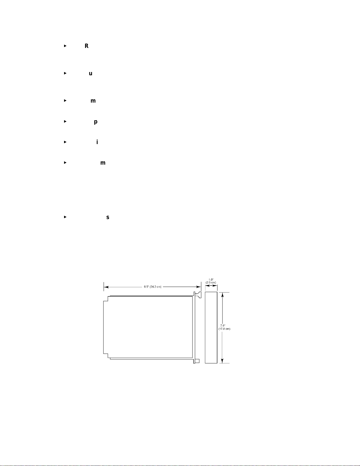
Dimensions:
Refer to Figure 1
Shipping Weight (approximate):
2 lbs (0.9 ki lograms)
Certification:
CSA certified for ordinar y , non-hazardous locations
System Sensitivity:
Sensitivity for t he standar d c ontroller is field adjustable over a range of 8
through 120 counts per second (cps) i n increments of 8 cps. The maximum
response distance is achieved at an 8 cps sensiti vi ty setting. For applications
involving high back gr ound r adiation potential, the system can be de-sensitized
by increasing the count rate required to actuate alarms. T he 120 c ps setting is
the lowest sensitivity.
Response Time:
Response to a saturating (hi gh intensity) UV source is typically 10 milliseconds
for the instant alarm outputs and 0.5 seconds for the area alarm outputs when
sensitivity is set for 8 cps and ti me delay is set for 0.5 seconds (minim um
settings)
Figure 1 - Controller Dimensions
- 2 -
Page 8

DETECTOR SPECIFICATIONS
<
Operatin g Voltag e:
290 Vdc ± 3V (prov ided from control ler)
<
Power Con sumption (each detecto r) :
0.29 Watts nominal, 0.5 Watt s maximum
1 mA nom inal, 1. 7 mA maximum
<
Temperature Range:
Operating: -40ºC to +125ºC (-40ºF to + 257ºF)
Storage: -55ºC to +150ºC (-65ºF to + 302ºF)
<
Dimensions:
Refer to Figures 2a and 2b
<
Detector Enclosure Materials:
Available in anodized copper-free aluminum or optional stai nless steel
<
Shipping Weight (approximate):
2 lbs (0.9 ki lograms)
<
Certification:
CSA, NRTL/C, NEMA 4X certified for hazardous locat ions
Class 1, Division 1, Groups B, C and D
IEC approval (Cl ass 1, Zone 1 Groups IIB+H2 T 5)
<
Spectral Sensitivity Range:
The detector responds to UV radiation over the r ange of 185 to 260 nanometers
(1850 to 2600 angstrom s)
<
Cone of Vision:
The Detector has a nominal 120 degree c one of vision
4.13"
0.25"
2.50"
5.50"
4, 1/4"
holes in
base fo r
mounting
0.5"
Figure 2a - Detector Dimensions
Figure 2b - S wivel M ount
Dimensions
- 3 -
Page 9
BASIC OPERATION - CONTROLLER
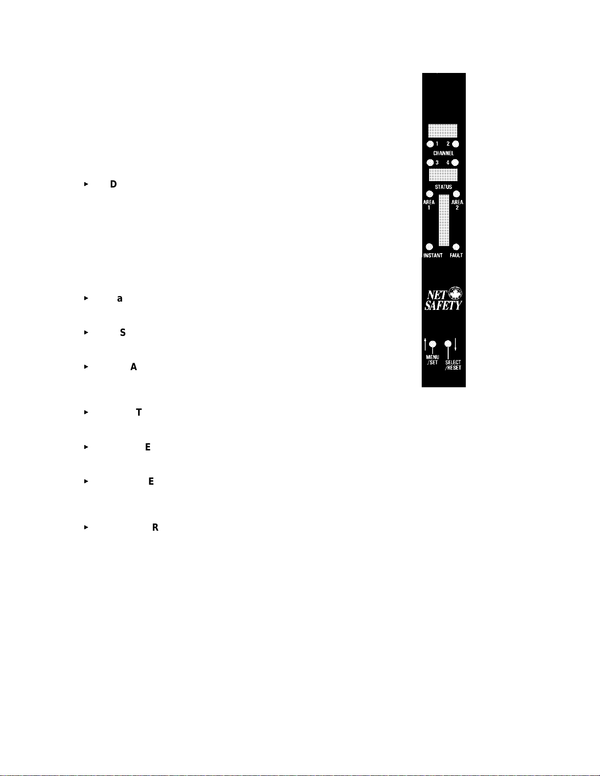
CONTRO LLER FACEPLATE DE S CRIPTIO N
The controller f ac eplate provides LEDs and two digit al displays f or
identifying status conditions, a bar gr aph display f or indicating an alarm
conditi on and MENU/SET and SELECT/RESET push-but ton switches
for testing and resetting the system. Refer to Figure 3.
<
Digital Displays - The upper digital display is normally off. If a
fir e alarm or visual integrity faul t is detected, it indi cates the
channel number of the alarm or fault. The digital displays
indicat e system status incl uding system error c odes, visual
integrity (vi) faults, system faults or fire alarms. T he lower
display shows ‘nor’ in normal oper ating mode. If more than
one channel is i n an alarm or fault condition the digital displays
will cycle through these channels. Since at least one di spl ay is
always lit they also function as a power indicat or .
<
Bar Graph Display - Norm ally off. F lashing when fir e
detected in any area.
<
INSTANT LED - (no time delay ) Flashes when any detector
signal exceeds the fir e sensit ivity setting.
<
AREA 1 & 2 LEDs - (Area 1 only for R1F) If the select ed
“voting” criteria of the area and the preset t ime del ay has
elapsed the corresponding LE D star ts flashing.
<
FAULT LED - flashes upon detection of an ov er all system fault
or vi fault.
<
CHANNEL LEDs - (1, 2 or 4 depending on model ) flash to i ndicate detect or in alarm
and remain illuminated until reset, after an alarm condition has ret ur ned to normal .
<
MENU/SET Push-button - is used to enter the m ain menu, t o toggle through menu
selections and i n c onjunction wit h the SELECT/RESET push-button to enter t he special
functions menu.
<
SELECT/RESET Pu sh-b u tton - is used for a basic system reset, m enu sel ec tion and
with the MENU/SET push-button to ent er the special functions m enu. This switch is
also used during the manual vi test.
OUTPUTS
Relay Outp uts:
The Instant, A rea and Fault relays have SP DT contacts rated 5 A mps at 30 Volts dc or 250
Volts ac.
The Instant and Area alarm relays are programmable for either normally energized or normally
de-energized operation and for latching or non- latching ( pr ogr ammabl e as a group not
individually). T he fault r elay is only nor mally ener gized. The relays can be configured with
jumpers for normally open or normally c losed contacts.
Figure 3 - Controller
Face-Plate
- 4 -
Page 10
RECOMMENDATION
The fault relay output should not be used t o ac tivate an automatic s hutdown procedure.
The fault output indicates a potential problem with the c ontroller, not an alarm c ondition.
Refer to Table 1 for a sum mary of the relay programmi ng options.
Table 1 - Selectable O utput Options
OUTPUT
1
AREA
Selectable Normal ly
Open/Closed
YYY
Selectable Normal ly
Energized/De-Energized
Selectable
Latching/Non-Latching
INSTANT Y Y Y
FAULT Y N
1
2
3
Area alarms are programmed together, not indi vidually
Fault relay is normally energized
Fault relay is non-latching
2
3
N
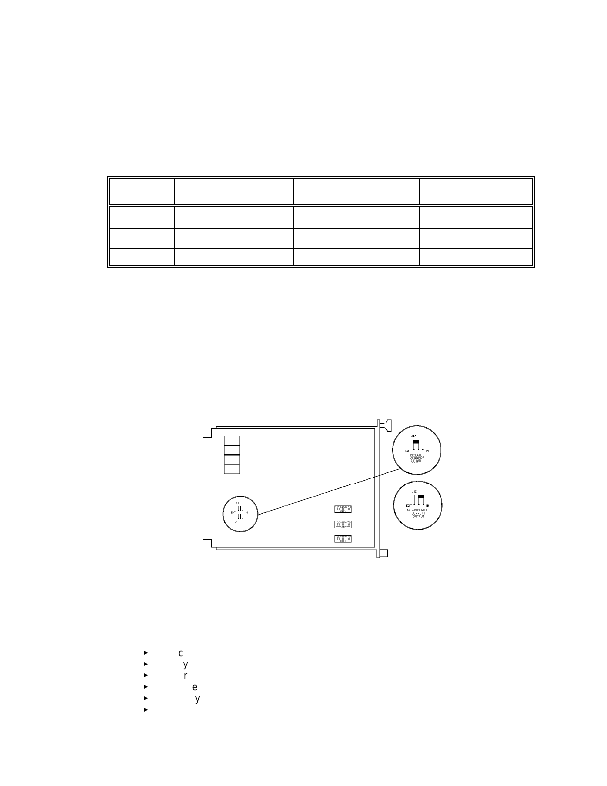
Current Outputs:
4-20 mA DC cur r ent outputs transmit system i nformation to other devices. The current out puts
can be wired for isolated or non-i sol ated operation by c hanging the jumpers as shown in
Figure 4. Refer to Unit IV, System Operation for a description of the c ur r ent output signal levels.
Figure 4 - Jumper Selections for an Isolated or Non-isolated Current
Output
PROGRAMMING OPTIONS
DIP switches locat ed on the circui t board are used to “program” var ious options including:
<
<
<
<
<
<
channel select ion,
system sensitivity,
fir e area vot ing logic,
tim e delay for fire area alarms,
relay latching/non-latching selec tion, and
relay energized/de-energiz ed sel ec tion.
- 5 -
Page 11

NOTE
Power to the controller must be cycled to make dip switch changes take effect .
EXTERNAL RESET
A normal ly open, m omentary closure switch connected between the external reset terminal and
the negative power terminal provides remote reset.
AUTOMATI C DIAGNOSTI CS AND FAULT IDENT IFICATIO N
The mi croprocessor-based controller featur es self-testing c ircuit r y that continuously checks for
problems t hat could prevent proper system response. When power is appl ied, the
microprocessor automatically tests memory . In the Norm al Operating Mode it cont inuously
monit ors the system to ensure proper functioning. A "watchdog" t imer i s maintained to ensure
that the program is running c or r ec tly.
The mai n loop of the operating program continuously cycles through the Automati c Visual
Integrity test, check ing each detector and its wiring. The micr opr ocessor can be interrupted by
any one of several status changes such as a fault or a "fire" signal from one of the detection
areas to take appropriate action.
If a system or v i faul t is detected the Fault LED flashes, digi tal display s and curr ent outputs
identify the nat ur e of the fault and the fault relay is de-energi z ed.
VOTING LOGIC (not applicable to R1F)
The controller can be DIP switc h c onfigured for eit her one or two monitoring areas. For a one
area configuration, all channels are consi dered as being in Area 1 and both A r ea alarm relays
will be activated together.
The dip switches can be set so that only one channel need be i n alarm t o ac tivate the area alar m
or any two channels must ‘vote’ (see a fire at t he same time) to acti vate t he ar ea alarm. The
instant alarm will be activated when any channel sees UV radiation exceeding the preset
sensitivity setting, no m atter what voting option is being used.
For a two area configurati on, channel one (one and two f or R4F) make up A r ea 1 and c hannel
two (three and f our for R4F) make up Area 2. With the R4F each Area alarm m ay be
programmed with different voting criter ia (ie. Ar ea 1 may be set so that ei ther channel one OR
channel two may ac tivate the area alar m, and Area 2 may be set so that both channels three
AND four must see the fire at the same t ime to activate the Area al arm).
DETECTOR
The detector responds to UV radiation over the r ange of 185 to 260 nanometers. It is not
sensitive to direc t or reflected sunlight nor to normal artificial li ghting.
The detector is housed in an explosi on- pr oof enclosure t hat is designed to meet most national
and international standards. It is available in anodized aluminum or optional stainless steel.
The detector is typically mounted with a swivel mounting assembly which i s recommended.
Other m ounting arrangements are possible.
- 6 -
Page 12

Unit II UV FIRE DETE CTIO N
SYSTEM APPLICATI ON
The detector responds instantly to ultraviolet r adiation emitted by a flame. It is designed for use
in hazardous locations and is suitable for use in outdoor applications.
Typical applications for UV detection system s are:
<
<
<
<
Petroleum Products Handling
<
<
<
<
<
<
Gaseous Fuel Handling
<
<
<
<
<
<
Other Processes
<
<
<
Automat ed fire pr otection system s al so have applications in any manufacturing or research
facility where the potential of fire may be low to moderate but the losses due to a f ire would be
high.
around highly combustible materials
if instantaneous response to fl ame is needed
where automated fire prot ec tion is required
to protect large capit al investments
petroleum loading t er minals
offshore platforms
pipeli ne st ations
tank far ms
refineries
engine rooms
butane and propane loadi ng and st or age
pipeli ne compressor stations
gas gathering facilities
LNG loading, transfer and stor age
hydrogen
gas turbines
paint spray booths
chemic al and petrochemical produc tion
powder coating booths
DETECTOR SENSIT IVITY
SPECTRAL SENSITIVITY RANGE
The UV fire detector r esponds to radiation wavelengths of 185 to 260 nanometers (1850 to 2600
angstroms). F igur e 5 illustrates the range of sensitivity and c ompares this range to other forms
of radi ation. Note that UV radiat ion reaching the ear th from the sun does not extend into the
sensitivity r ange of the detector. Nor does radiat ion from normal ar tif icial lighti ng, such as
fluor escent, mercur y vapor and i nc andescent lamps.
- 7 -
Page 13

Figure 5 - Various Spectral Distributions
NOTE
Some mercury v apor lam ps c an oper ate for extended periods with cracked or damaged
envelopes and will then emit UV radiation in the range of the detector. Remove defective
mercury vapor lam ps from service.
The UV sensor responds to radiati on other than ultr avi olet. X-rays can activate the detector and
are often used i n industrial inspection. I t may be necessary to disable the system if X-ray
inspection is conducted nearby.
UV radiation other than that produced by an actual fire is referred t o as “back gr ound UV .” An
example of a high level of bac k gr ound UV c ould be the case of a flare stack si tuated outside of a
buildi ng. The UV radiation produced by this flar e may be detected when a door to the buildi ng is
opened. Windows or refl ec tive surfaces may also result in unusually high levels of UV radiation
entering the building from the flar e. In a situation like this, the fire detection system response
must be carefully c hec k ed and the sensitivity level adjusted high enough so that this
“background” UV will not cause false alarms.
Caution m ust be exercised i f the detection system is turned off, since the hazar dous area will not
be protected.
NOTE
Ultraviolet detec tors are sensitiv e to arc welding and if t his type of radiation can be
expected, nuisance alar ms must be contr olled through proper application including
careful positioning and shielding of the detectors . Some applications may r equir e a
UV/IR system.
- 8 -
Page 14

CONE OF VISION
The fire detector has a nominal 120 degree cone of vision. F igur e 6 shows the cone of vi si on
and detector response to a UV source at vari ous di stances. The practi c al application distance is
up to about 50 f eet (15 meter s). The distance is directly related to the intensity of the ult r aviolet
radiati on sourc e. Programming the cont roller t o r equire a high count rate results in low system
sensitivity. Consider that UV absorbi ng c hemical vapors may be present. (See Appendix C)
Figure 6 - Detector Cone of Vision
SYSTEM SENSITIVITY
The UV tube count r ate generated by differ ent fir es at the same distance is unpredictable.
Generall y, if a fir e doubles in size the t ube r esponse is inc r eased by about 60 percent.
Controll er sensitivity and t ime del ay settings for various applicati ons i s dependent on the severi ty
of the hazar d and the action required if a fir e oc curs. The system can be adjusted to v arious
sensitivity levels by programming the cont r oller to respond at a pre-determined detector count
rate which is dependent upon the intensity of the ultrav iolet radiation reaching the detector ,
which in turn depends on the type of fuel, temperature, flame size, distanc e from the detector
and concentration of UV absorbi ng vapors present.
Programming the controller to respond to a low count rate r esul ts in high system sensit ivity.
Unit III SYSTEM INSTALLATION
INSTALLATION
GENERAL WIRING RE QUIREMENTS
NOTE The wiring procedures in this manual are intended to ensur e proper functioning of the
device under normal condit ions . However, becaus e of the many variat ions in wiring
codes and regulations, total compliance to these ordinances cannot be guaranteed. Be
certain that all wiring complies w ith applicable regulations that r elate to the installat ion of
electrical equipment in a hazardous area. If in doubt, consult a qualified official before
wiring the system.
- 9 -
Page 15

Shielded cable is highl y r ec ommended for power input and signal wires to protect against
interference caused by extraneous electri cal 'noise'. Relay outputs do not require shielded cable.
Recomm ended detector cabl e is four conduct or , shielded cabl e, 18 AW G, rated 300V. If the
wiring cabl e is installed in conduit, the conduit must not be used for wiring to other electric al
equipment . Detectors can be l oc ated up to 2000 feet ( 600 meters) from the controller.
Water will damage electronic devices. M oisture in the air can condense within electric al conduit
and drain int o the enclosure, ther efore, water-pr oof and explosion-proof c onduit seals are
recommended to prevent water accum ulation wit hin the enclosure. S eals should be located as
close to the device as possible and not more than 18 inches (46 cm) away. Explosion-pr oof
installations may r equire an additional seal where conduit enters a non-hazardous area.
Conform to local wiring codes.
When pour ing a seal, use a fibre dam to assure proper formation of the seal. The seals should
never be pour ed at temperatures below freezi ng.
The jacket and shielding of the cable should be str ipped back to permit the seal to form around
the indivi dual wires. This will prevent air, gas and water leak age through the inside of the shiel d
and into the enclosure.
It is recommended that explosion- pr oof drains and conduit breathers be used. In some
applicat ions, alternate changes in temper ature and baromet r ic pressure can cause 'breathing'
which allows moist air to enter and c irculat e inside the conduit. Joint s i n the conduit system ar e
seldom tight enough to prevent this 'breathing'.
CONTRO LLER WIRING
NOTE
The controller contains semiconductor dev ic es that are susceptible to damage by
electrostat ic discharge. An elect r os tatic charge can build up on the s kin and discharge
when an object is t ouc hed. Therefore, us e c aution when handling, taking c ar e not to
touch the term i nals or elec tronic components. For more information on proper handling,
refer to the A ppendix .
The controller can be configured for isolated or non- isolated current outputs by changing j umpers
on circuit board as per Figure 4. Figures 7a, 8a, and 9a show the proper wiring for non -isolated
current outputs and Figures 7b, 8b and 9b show wiring f or isolated current outputs.
- 10 -
Page 16

Figure 7a - Wiring for R1F with Non-Isolated Current Output
- 11 -
Page 17

Figure 7b - Wiring for R1F with Isolated Current Output
- 12 -
Page 18

Figure 8a - Wiring for R2F with Non-Isolated Current Output
- 13 -
Page 19

Figure 8b - Wiring for R2F with Isolated Current Output
- 14 -
Page 20

Figure 9a - Wiring for R4F with Non-Isolated Current Output
- 15 -
Page 21

Figure 9b - Wiring for R4F with Isolated Current Output
- 16 -
Page 22

POSITION AND DENSITY OF DETECTORS
The detector has a nominal 120º cone of vision. In an application such as a loading rack with a
ceiling height of 25 feet ( 7.5 meters) where it is desired to have complete detector c overage at
floor lev el and a detector is mounted 2 f eet (0.6 meter) from the ceiling and pointed straight
down, the distance from the detector to the desi gnated level would be 23 f eet (7 meters) and
because of it s 120º cone of vision the detec tor would cover a circular area 80 feet ( 24 meters) in
diameter at floor level. A sketch of the area to be covered will indicate the number of detectors
required to monitor the area. Detector s should be placed as close as practical to the expected
fir e haz ard.
NOTE
Do not mount UV detec tors close to t he c eiling of enclosed buildings if smoke m ight
accumulate before the break-out of flame. It is prefer able to mount the detectors on
walls a few feet (or about 1 meter) below the ceiling where they may respond before
being obscured by smoke. Consider shortening tim e delay s ettings when sm ok e is
expected to accum ulate during a fire. If dens e s m ok e is lik ely to accumulate prior t o
flame (as in an elect r ic al fire), supplement UV detectors w ith other protect ion.
MOUNTING THE DE TECT OR
Locate detector s t o ensure an unobstruc ted view of the area to be monitored and where
accessible for cleaning the detector window and vi reflecting surface. Take care so dirt and dust
will not accumulate and obscure the detector viewing window. Det ec tors mounted outdoors
should be pointed downward to prevent the cone of v ision fr om scanning the horizon where long
duration l ightning flashes or far- off arc welding may ac tivate the detector. To m inimize dirt
accumul ation around the vi surfaces, mount the detectors so that t he internal vi tube is on top.
The silver ex ternal reflector shoul d be placed direct ly ov er the vi tube. Refer to Figures a and 2b
for the detector and swivel mount ing assembly di mensions. Refer to Figure 10 f or a diagram of
Figure 10 - Detect or with Sw iv el M ount Assembly
the assembled detec tor and swivel assembly.
DIP SWITCH SETTINGS
NOTE
To make DIP switch changes take effect, cycle power to the controller off then on.
The DIP switches on the controller c ircuit boar d must be properly pr ogrammed before applying
power to the system. There are three banks of 8 position DIP switc hes which are OFF or ON to
select area and detec tor combi nations, controller sensiti vity, fire voting logic, output latching and
tim e delay. See Figur e 11a below. The switch banks are number ed from top to bottom as SW
5, SW 4 and SW 3.
- 17 -
Page 23

Individual ON/OFF switc hes are designated “SW X.Y where ‘X’ refers to the switch bank and ‘Y ’
refers to t he swit c h number on ‘X’ bank. See Figure 11b.
Figure 11a - Relay and Dip Switch
Positions
CHA NNEL SELECTION
Switches SW 3.1 through SW 3.4 enable the detector s that are to be connected to the control ler.
The appropriate switch must be set to t he ‘OFF’ position to enable each det ec tor connected. If a
switch is off but no detector is connected i n that locat ion the controller will indicate a fault. If a
switch is on, but a det ec tor is connected, the controller will appear to be operating cor rectly but
that detector will be eliminated from the Automatic vi test sequence and any fault s occurring in
its circuit will not be annunciated.
R1F, R2F and R4F
<
R2F and R4F
<
R4F only
<
SW 3.1: OFF: detector 1 connected
ON: detector 1 not c onnected
SW 3.2: OFF: detector 2 connected
ON: detector 2 not c onnected
SW 3.3: OFF: detector 2 connected
ON: detector 3 not c onnected
Figure 11b - Dip Switch
<
CONTRO LLER SENSITIVITY ADJUSTME NT
Switches SW 4.1 through SW 4.4 set c ontroller sensit ivity in 8 cps (c ounts per second)
increments.
<
<
<
<
The switch values are added together. These switches are fact or y set to a sensitivity of 24
counts per second, as shown in the example.
SW 3.4: OFF: detector 4 connected
ON: detector 4 not c onnected
SW 4.1 ON: 8 cps
SW 4.2 ON: 16 cps
SW 4.3 ON: 32 cps
SW 4.4 ON: 64 cps
- 18 -
Page 24

Example
FIRE AREA VOTING SEQUENCE (not applicable to R1F)
SW 4.5, SW 4.6 and SW 4.8 select voting sequence which can be Fire A r ea 1 only (all detectors
in one area) or F ire Area 1 separate from Fire Area 2. When separate, F ire Area 1 consists of
detector 1 (1 and 2 for R4F) and F ire Area 2 consists of detector 2 (det ec tor 3 and 4 for R4F ).
Switch SW 4.7 should be placed in the ‘OFF’ positi on at all times.
Fire Ar ea 1 S epar ate from Fire Area 2:
: SW 4.1 ON
SW 4.2 ON sensitivity
SW 4.3 OFF = 24 cps
SW 4.4 OFF
<
<
<
Fire Ar ea 1 only:
<
<
<
<
RELAY OUTP UTS LATCHING/NON-L ATCHING
The alarm relays are programmed toget her for l atching or non-l atching operation (the f ault relay
is only non-latching).
<
SW 4.7 OFF
SW 4.8 ON
SW 4.5 programs Fire Area 1 (detector 1 f or R2F) (detect or s 1 and 2
for U4F)
OFF: votes one of two detectors (always OFF for R2F)
ON: vot es two of two detectors
SW 4.6 programs Fire A rea 2 (detector 2 for R2F) (det ec tors 3 and 4
for U4F)
OFF: votes one of two detectors (always OFF for R2F)
ON: votes two of two detectors
SW 4.8 OFF
SW 4.7 OFF
SW 4.6 OFF
SW 4.5: OFF: vot es any one of all detectors
ON: vot es any t wo of all det ec tors
SW 5.1: ON: non-latching operat ion
OFF: latching operation
NOTE
Latched outputs ar e unlatched by activat ing the RESET switch or remote reset.
RELAY OUTPUTS ENERGIZED/DE-ENERGIZED
The area and instant alarm relays can be programmed for normally ener gized or norm ally deenergized operat ion using SW 5.2 . The fault relay is always normally energized. SW 5.2 is
factor y set to de-energized operation (ON)
<
SW 5.2: OFF: normally energized oper ation
ON: normally de-energiz ed oper ation
- 19 -
Page 25

TIME DELAY FOR AREA ALARM S
NOTE
Time delay affects the Area alarm s only ; the instant alarm oper ates as soon as a flame is
detected.
The time delay for the Area al ar ms is set using SW 5.3 to SW 5.7. If all of t he switc hes are
placed in the ‘OFF’ position the time delay will be 0.5 seconds (minimum setting).
<
<
<
<
<
<
If switc h 5.8 is "OFF" then in Bypass mode:
- the current output is 4 mA
- the Fault Relay state remains unchanged (if it was energized, it remains energized; if i t
was de-energized, it r emains de-energi z ed)
If switch 5.8 is "ON" then in Bypass mode:
- the current output is 3 mA
- the Fault Relay is de-energized
The total time delay is the added value of the switches turned ON. S witches can be turned ON
in any com bination for a time delay from 0. 5 to 15.5 seconds in half second increm ents. These
switches are fact or y set to a 3.0 second time delay as shown in the example below.
Example
: S W 5.3 OFF tim e delay
SW 5.3-7: OFF: 0.5 sec. time delay
SW 5.3: ON: 0.5 sec. time delay
SW 5.4: ON: 1 sec. time delay
SW 5.5: ON: 2 sec. time delay
SW 5.6: ON: 4 sec. time delay
SW 5.7: ON: 8 sec. time delay
SW 5.4 ON = 3.0 sec.
SW 5.5 ON
SW 5.6 OFF
SW 5.7 OFF
NOTE
SW 3.5 through SW 3.8 and SW 5. 8 ar e not used.
RELAY SETTINGS
There are f our relays on the contr oller circuit board ( three for t he R1F-UV) that c an be c onfigured
for normally OPEN or normally CLOS E D oper ation by moving the jumper s which are located
below the relays. S ee Figure 11a for t he location of the rel ay s on the c ircuit boar d and Figure
11c for t he settings.
Unit IV SYSTEM OPERATION
Figure 11c - Relay Settings
- 20 -
Page 26

SYSTEM OPERA TION
STARTUP P ROCEDURE
CAUTION
Placing the controller in the By pass mode inhibits its outputs, preventing actuation of any
exti nguishing or alarm circuits that are connec ted. For m aximum safet y , however,
secure output loads (remov e power from any devic es that would normally be actuated by
the system) before manually testi ng the system. Remember to place this same
equipment bac k into service when the test i s complete.
1. After setting the DIP switches and mak ing all electric al connections, apply power
2. Perform the Checkout Procedure.
3. If the controller appears to be operating normally (performs power-up count down
NOTE
Be sure that t he detector is corr ec tly aimed at the potential hazard and that no
obstructions interfere with its line of vision. UV abs or bing gases should not exist
between the det ec tor and the potential hazard.
CHECKOUT P ROCEDURE
CAUTION: When test ing the system, be sure to secure all output devices to prevent unwanted
activation of this equipment and remember to place these same devices bac k into service w hen
the check-out is c omplete.
MANUAL vi CHECK/COUNT TEST
The Automatic vi (visual i ntegrity) feature chec k s the detectors for c orrect response.
The v isual integr ity test and the c ount test are performed at t he same tim e.
1. Pl ac e the controller in the bypass mode ( all output s i nhibited) by k eeping the
to the controller.
and then shows ‘Nor’ on the display), r emov e mechanical blocki ng devic es and
restore power to the ex tinguishing loads.
MENU/SET switch activated until ‘Chc’ ‘Err’ or ‘bPS’ are shown on the digi tal
displays. Rel ease the switc h and ac tivate it again until ‘bP S ’ is shown on the
upper display, then activate the SELECT/RESET switch. The upper digital
display will show ‘Chn’ and the lower digital display will show counts per second.
2. Activate the MENU/SET switc h again to toggle through the available channels.
When the desired channel is shown on the upper display, activat e the
SELECT/RESET switch.
3. While in the bypass mode, the lower display will show the counts per second
produced by the backgr ound UV in the detector ’s range of v ision. Act ivating the
SELECT/RESET switch will perform the manual vi test, a si gnificant increase i n
the count displayed should be observed. (Counts should be greater t han 150
and less than 400. If the counts read are not with in this range then, the lens and
refl ec tor need cleani ng or the vi adjustment Allen screw on the tube module
needs to be repositioned ( only av ailable on t he tube modules with aluminum
shroud)
- 21 -
Page 27

4. Cleaning Viewing Window and Ref lector, When cleaning the viewing window
and refl ec tor use a clean lint free c loth and cleaning solution provided with
detectors. Use only r ec ommended cleaning solutions, as some cleaners can
leave a residue that can block UV lights.
5. Repositioning vi Adj ustment Allen Screw, The UV sensor module has an
adjustment Allen Scr ew (Aluminum Shrouds Only) . This adjustment controls the
amount of light released from the vi source duri ng visual integrit y testing. T o
increase the amount of UV light released reverse the A llen Screw, this will open
the orifice and al low more li ght to pass through.
6. To exit the bypass mode, activate t he MENU/SET switch repeatedly until ‘tSt’ i s
shown on the upper display. Now acti vate t he SELECT/RESET switch.
NOTE: The Automatic vi system continuously monitors the operation of t he det ector but does not
monitor external relays or equipment that may be operated from the relay outputs. It is
important that the system be manually checked using the MANUAL check procedure on
a regular basis. The whole syst em (including ext ernal equipment) should be checked
periodically using a UV Test Lamp to simulate a fire.
MANUAL CHECK PROCEDURE
The whole system should be chec k ed per iodical ly with a UV test lamp to make sure that the
detectors are not obstr uc ted, that the ar ea ‘seen’ by t he detector has not changed and that there
is no faul t in the vi circuit.
CAUTION
Secure all output loads c onnec ted to the contr oller to prevent unwant ed ac tivation.
1. Pl ac e the channel to be t ested in bypass mode as described in t he ‘MAIN MENU’
2. Dir ec t the UV test l ight into a detector viewing window. The count s per second
3. Turn off the UV source.
4. Repeat t he test for all detector s i n the system.
5. After all detectors have been checked, return the system t o the normal oper ating
6. Restore power to out put loads or remove any m ec hanical bl oc k ing devices.
ALTERNATE TEST PROCEDURE
After eac h channel is of fered f or sel ec tion in t he by pass mode a final ‘tSt bPS’ selection is
offered. All channels are now in the test by pass m ode. In this m ode the counts per second,
normally seen when a channel is in bypass, are not seen and t he Channel, Instant, and A r ea
LEDs will operate as they would i n the normal oper ating mode (i.e. flash when a fire c ondition
exists etc .), but the relay and current out puts are inhibi ted. This is an excellent way to test
sensor sensitiv ity setti ngs and to assure that if a fire occ ur s the c ontroller will respond. Activate
the SELECT/RESET switch, whil e in this m ode, to return to the normal oper ating mode.
section of this manual .
displayed on the lower display should inc rease to an alarm level.
mode.
- 22 -
Page 28

NORMAL OPERATION
FIRE RESPONSE
When the controller receives a ‘fire’ signal from any det ec tor in the system, it is compared to the
stored inf ormati on of the program. If the signal level is greater than t he programm ed sensit ivity
setting:
1. The instant alarm relay and the appr opr iate current output change status and the
instant LED flashes.
2. The upper display cycles through all detectors responding to the fire (CH1, CH2,
CH3, or CH4).
3. The lower digital display indicates a fire (‘Fir’).
4. One or more channel LE Ds tur n on ( blinking), indic ating the channel ( s) det ecting
UV radiation.
If t he si gnal level is great er than the program med sensitivity setting f or longer than the preset
tim e delay and the select ed ‘voting’ criteria has been satisfi ed, the appropriat e Area outputs
change status and the corresponding A r ea LE D is flashing. The bar graph displ ay is also
flashing.
NOTE
When a fire signal is no longer pr es ent, the channel LED(s) and the instant and area
LEDs will be latched on until manually reset (LE Ds ar e on, but no longer flashing).
Current Outputs
4-20 mA DC cur r ent outputs transmit system i nformation to other devices. The current out puts
can be wired for isolated or non-i sol ated operation by c hanging a jumper c onnec tion as shown in
Figure 4. The c ur r ent output can have a maximum exter nal loop resistance of 600 ohms.
Table 2 shows the current output levels for various situat ions.
- 23 -
Page 29

Table 2 - Current Outputs
Current Output Situation
0 mA Off or Shorted si gnal output, or loss of power
1 mA Fault
2 mA Power Fault
4 mA Normal
5 mA VI fault channel 1
6 mA VI fault channel 2
7 mA VI fault channel 3
8 mA VI fault channel 4
9 mA VI fault mor e than one channel
15 mA Instant alarm channel 1
16 mA Instant alarm channel 2
17 mA Instant alarm channel 3
18 mA Instant alarm channel 4
19 mA Instant alarm more than one channel
19.5 mA Fire (A r ea alarm)
AUTOMATI C DIAGNOSTI CS AND FAULT IDENT IFICATIO N
If a fault is detected:
<
<
<
<
<
Refer to Table 3 to identify t he er r or messages. If more than one error i s occur ring, the message
will continuously cycle through all the errors, changing every few seconds.
the Fault LE D flashes,
the digital display s i dentify that a fault has occurred,
the current outputs change state,
the fault relay output becomes de-energized, and
if a specifi c individual det ec tor fault is detected ( exampl e, wiring probl ems), the
corresponding channel LE D will be on.
- 24 -
Page 30

Table 3 - Error Codes
Upper
Display
Lower
Display Error What to do
290 gnd
290 OLo
290 OHi
12 OUT
5OUT
24H OUT
24L OUT
ch OiH
chx
2
OiL
rSt E71
Ert Err
CFg Err
E91 Err
E92 Err
E94 Err
E97 Err
Grounding problem with
detector 290 Vdc supply.
+290 Vdc detector power too
Check wiring t o detector, 290Vdc may
be shorted to ground
Contact Factory
low.
+290 Vdc detector power too
Contact Factory
high
Internal 12 V dc supply out of
operating range.
Internal 5 V dc supply out of
operating range.
1
1
Controll er supply is greater
Recycle power and call f act ory if
problem persists
Recycle power and call f act ory if
problem persists
Check your power supply
than 32Vdc
Controll er 24 Vdc supply is
Check your power supply
less than 18Vdc
Visual i ntegrity err or ( S ignal
Contact Factory
received is too hi gh)
Visual i ntegrity err or ( S ignal
received is too l ow)
Reset push-button is
damaged, or has been
Clean detector wi ndow and reflector
Check for proper wiring connect ions
Make sure no magnetic objects are in
close proximity to the switch
activated for more t han 15
seconds
External reset switch short
error
Configur ation error; incorrect
dip switch settings
Make sure external reset switch is not
damaged or shorted t o gr ound.
Check dip switch settings and recycle
power
System RAM error Contact Factory
Power is not stable Contact Factory
EEPROM data not correct Contact Factory
EEPROM reading, or writing
Contact Factory
not correct
1 If an internal power supply problem occurs, recycle power to the controller. If the
problem persists, cont act supplier
2 If more than one channel has a vi error, the upper display will sequentially show each
channel number
If a fault has occur r ed, but no longer exists, the fault LED will remain illuminated and the displays
will alternate between ‘nor’ and ‘Err Fnd’. To f ind out what the f ault was, enter the error c hec k
mode by keepi ng the MENU/SET switch acti vated unt il ‘Chc Err’ is displayed, then ac tivating the
SELECT/RESET swit c h. The display should now show ‘dSP Err’. Activate the SELECT/RESET
switch and the f ault error codes are sequenti ally di spl ay ed. Once all fault s have been displayed,
‘Clr Err’ is displayed. To clear the fault codes, activate the SELECT/RESET switch.
- 25 -
Page 31

MAIN MENU
The mai n menu is entered by ac tivating the MENU/SET switch for approximately 5 seconds until
‘Chc’ ‘Err’ or ‘bPS’ is shown on the displays. Repeatedly ac tivating the MENU/SET switch will
toggle through the selections. When the desi r ed selection i s shown on the displays, activate the
SELECT/RESET swit c h to choose the selection. To exit the main menu without c hoosing an
option, t oggle through the selec tions until ‘r tn’ is shown on the lower display.
ERROR CHECK MODE ( E rr Chc)
This selection is shown when a fault is occur r ing or has occurred when accessing the m ain
menu. Ent er the main menu and activate t he SELECT/RESET switch when ‘Chc’ is shown on
the upper display and ‘Err’ i s shown on the lower display. ‘dsP’ will be shown on the upper
display and ‘Err’ on the l ower di spl ay . To see the errors activat e the SELECT/RESET switch.
The controller will display each error for approximately 5 seconds. Once all errors have been
shown, ‘Clr’ will be shown on the upper display and ‘Err’ on the lower. Activate the
SELECT/RESET swit c h to clear the err or s and return to the normal operati ng mode.
If it is not necessary to see what errors have been logged, but only to clear them, ac tivate the
MENU/SET switch when ‘dsP’ ‘Err’ is shown. The ‘Clr’ ‘Err’ selection will be displayed. Activate
the SELECT/RESET switch to clear the errors and retur n to the normal operating mode.
NOTE: If no er r or s exist, this function is hidden and can not be acc es s ed.
BYPASS MODE (bPS)
This selection is used for testing detector oper ation without activating al ar m outputs. To enter
this mode, first enter the main menu, toggle through the selec tions using the MENU/SET swi tch
and activate the SELECT/RESET switch when ‘bPS’ is shown on the lower display. ‘Ch1' will be
shown on the upper display and the UV seen by the detector is shown on the lower display in
counts per second. A range of between 150 and 400 cps counts per second is expect ed.
Activating the SELECT/RESET switch while a channel is in bypass will perform the manual vi
test. A signific ant increase in the ( c ps) c ounts per second should be observed on the lower
display.
Activating the MENU/SET switch will toggle through all of the ac tive channels and then show
‘tSt’ on the upper display and ‘bP S ’ on the lower display. In this manual test mode, all alar m
outputs are inhibited, but the faceplate indicators will operate as in the normal operating mode.
If a flam e occurs or UV test lamp is used to acti vate t he detectors the f ac eplate indicators
operate as in the normal operating mode, but the alarm outputs will not activate. To exit the
bypass mode, activat e the SELECT/RESET switch while ‘tSt bPS’ is displayed.
SPECIAL FUNCTION MENU
To enter the special func tion menu activate both switches sim ultaneously for 20 seconds, until
‘FoP’ is shown on the lower display. This menu is a little harder to enter because it is not
intended for general use. The items in this menu are used for system maintenance and
calibration of equipment. Fop, CuC and Adr Set can be displayed by repeatedly activation the
MENU/SET push but ton when in the special function menu until the desired m ode is displayed.
Press the SELECT/RESET button to choose the desired mode.
- 26 -
Page 32

FORCED CURRENT OUTP UT MODE (FoP)
The forc ed current output mode is used to check the c urrent output calibration and the operati on
of any devices connected to the current outputs.
To enter the forced current output mode, enter the special funct ion menu. When ‘FoP’ is shown
on the lower display ac tivate the SELECT/RESET switch. Upon successful entry int o this mode
the upper display will flash ‘gPn’. Activate the MENU/SET switch until the desi r ed ar ea output is
reached (‘gPA’ = Area 1 and gPb’ = Area 2), then activate the SELECT/RESET switch.
When an ar ea has been chosen for forc ed c ur r ent output, the upper display will alternate
between ‘GPn’ and ‘FoP’ and the lower display will show what type of current output is being
placed on the current output l ine:
Flt -> Fault (1mA)
POE -> Power Error (2mA)
Nor -> Norm al (4mA)
OP1 -> Visual Integrity E r ror Channel 1 (5m A )
OP2 -> Visual Integrity E r ror Channel 2 (6m A )
OP3 -> Visual Integrity E r ror Channel 3 (7m A )
OP4 -> Visual Integrity E r ror Channel 4 (8m A )
OPA -> Visual Integrity Error on more than one channel ( 9mA)
in1 -> Instant A larm Channel 1 ( 15mA)
in2 -> Instant A larm Channel 2 ( 16mA)
in3 -> Instant A larm Channel 3 ( 17mA)
in4 -> Instant A larm Channel 4 ( 18mA)
inA -> Instant A larm on more than one channel ( 19mA)
Fir -> Area Alarm (19.5mA )
The controller will start with the Fault output and the push buttons are used to scroll up and down
through the different outputs. To exit t his mode, scrol l down past the Fault out put selection until
‘rtn’ is display ed then wait 10 seconds. The controller will return to the normal operating mode.
CURRENT CALIBRAT ION MODE (Cu C)
The next sel ection in the special function menu is the current c alibration mode. T he c ur r ent
outputs are fac tory calibrated, howev er this mode can be used to calibrate t he c urrent outputs of
the control ler if they are not proving the correct cur r ent values. Upon successful entry into this
mode the upper display will flash ‘gPn’. Activate the MENU/SET switch unti l the desired area
output is reached ( ‘gPA’ = Area 1 and ‘gPb’ = A r ea 2) , then activate t he SELECT/RESET
switch. Once an area has been selected, the upper displ ay will alternate between ‘CuC’ and the
area that is being calibrated. The lower display will show a constant which will rise and fall as the
current i s adj usted ( c onstant does not show the current on the output s), and the instant LED will
flash. Place a milliamp meter between the Area current output and common ground. Use the
push buttons to raise and lower the c ur r ent. Once the c ur r ent measured is as close to 4mA as
possible, do not activate any switches for 10 seconds. A fter 10 seconds have gone by the
number shown on the lower display will change to a much higher number. The instant LED will
be exti nguished and the area LED will begin flashing. Thi s t ells the operator to calibrate the
current output for the high end of the c ur r ent output range. Use the push-but ton to raise or lower
the current output until it is as close as possible t o 20 mA. Do not ac tivate any switches for 10
seconds and the controller will return to the normal operating mode.
ADDRESS SET MODE (do not use)
- 27 -
Page 33

Do not use the final selection which is Address Set Mode.
Unit V MAINTENANCE
ROUTINE MAINTENANCE
The detector requires no periodi c c alibration. To m aintain maximum sensitivity, the viewing
windows and reflector s should be cleaned on a routine basi s dependi ng on the type and amount
of contaminants i n the area.
The rubber O-r ings on the detector housing ar e used to ensure it is waterti ght. The housings
should be opened periodi c ally and the O - r ings inspected f or br eak s, c r acks or dryness. To test
them, r emove the O-ri ngs from the detector housing and stret c h them slightly. I f cracks are
visible, t he O-ring should be replaced. If they f eel dry to the t ouc h, a thin coating of lubricant
should be applied. When r e- installing the O-rings, be sure that they are properly seated in t he
groove on the housing.
These O-rings must be properly i nstalled and in good c ondition to pr event water from entering
the detector and c ausing failure. The l ife expectancy of rubber O-rings varies, depending on the
type and amount of contaminants present in the area. The person who mai ntains the system
must rel y on experience and common sense to determine how frequently the rings should be
inspected. A c oating of lubricant shoul d also be applied to the enclosure threads bef or e
reassembling the detector to help prev ent moistur e from entering.
CAUTION
The O-ring should be lubr ic ated with polyalphaolefin gr eas e, such as GRS-450 m ade by
CPI Engineering. Silicone based lubric ants should never be used if c atalytic type
combustible gas sens or s ar e being us ed in c onjunc tion with the UV detectors, s inc e
silicone lubricant on or near the combustible gas sensor will cause permanent dam age to
the sensing element.
TROUBLESHOOTING
The Automatic vi (visual i ntegrity) feature continuously checks the detectors for c or r ec t
response. If a problem is detec ted, the f ault LED will turn on, the upper digital display will
indicat e whi c h c hannel has the problem and the lower digital display will show “OIL” or “OIH” The
fault relay will become de-energized.
If a fault is in the detect or or wir ing, the upper display will indicate which detector is affected.
The lower display will indicate by code number the type of fault. If the fault is in t he
microprocessor circuitry, the fault LED will turn on, but the upper digital display will remain blank.
Refer to Table 3 for a detailed ex planation of the status/fault codes.
- 28 -
Page 34

DEVICE REPAIR AND RETURN
The detector and controll er ar e not designed to be repair ed by the customer i n the field. If a
problem should develop, first carefully check for proper wiring and programming. If it is
determined that the problem is caused by an el ec trical malfunction, the unit must be returned to
the factory for r epair.
Net Safety Monitor ing Inc encourages it s di st r ibutors to mak e advance replacement units
available t o the user during the warranty period. Thi s al lows Net Safety Monitoring Inc. to take
tim e to repair the unit completely while users keep their operations running with the advance
replacement unit.
Prior to returning i tems, contact the nearest distribution offi c e so that an RMI (Return M aterial
Identificat ion) number can be assigned. A written statement describing the malfuncti on must
accompany t he returned item to sim plify fi nding the cause of t he fail ur e and reduce the time and
cost of the r epair. Pack the item to protect it from damage and use an anti - static bag or
aluminum-backed c ar dboar d as prot ec tion f r om electr ostatic discharge.
- 29 -
Page 35

Appendix A Net Safety Monitoring Inc. E l ectrostatic
Sensitive Device Handling Procedure
With the tr end toward increasingly wi despread use of micr opr oc essors and a wide variety of
other elect rostatic sensitive sem iconductor devices, the need for careful handling of equipment
containi ng these devi c es deserves more att ention than i t has received in the past.
Electrost atic damage c an oc c ur in several ways. The most familiar is by physical contact.
Touching an obj ect causes a discharge of electrostatic energy that has built up on the skin. If t he
charge is of sufficient magnitude, a spark will also be visible. This voltage is oft en more than
enough to damage some electroni c c omponents. Som e devi c es can be damaged without any
physical contact. Exposure to an electric field can cause damage if the electri c fiel d exceeds the
dielect ric breakdown voltage of the capacitive element s within the device.
In some cases, perm anent damage is instantaneous and an immediate m alfunct ion is realized.
Oft en, however, the symptom s are not immediately observed. Perform anc e may be marginal or
even seem ingly normal f or an indefi nite period of time, f ollowed by a sudden and mysterious
failure.
Damage caused by elec trostatic discharge can be virtually eliminated if the equipment is
handled only in a static safeguarded work area and if it is transport ed in a package or container
that will render the necessary protection agai nst static elec tricity. Net Safety Moni toring Inc.
modules that might be damaged by static electri c ity are carefully wrapped in a static prot ec tive
material bef or e being packaged. Foam packaging blocks are also treated wit h an anti-static
agent. If it should ever become necessary to return t he module, it is highl y recomm ended that it
be carefully packaged in the origi nal carton and static protective wrappi ng.
Since a static safeguarded work area i s usually im pr ac tical in most field i nstallati ons, c aution
should be exercised to handle the module by it s metal shields, taking care not to touch el ec tronic
components or t er minals.
In general, always exercise all of the ac cepted and proven precautions that ar e nor mall y
observed when handling electrostat ic sensitive devices.
A warning label is placed on the packaging, identifying those units that use elec trostatic sensit ive
semiconductor devices.
*Published in Accordance with E1A
standard 471
i
Page 36

Appendix B Record Of Dip Switch Settings
DIP SWITCH ON OFF
SW3.1
SW3.2
SW3.3
SW3.4
SW3.5
SW3.6
SW3.7
SW3.8
SW4.1
SW4.2
SW4.3
SW4.4
SW4.5
SW4.6
SW4.7
SW4.8
SW5.1
SW5.2
SW5.3
SW5.4
SW5.5
SW5.6
SW5.7
SW5.8
ii
Page 37

Appendix C Common Ultra-V i ol et Absorbing Gases
Since the UVC120 fire detector is designed to detect fires by responding to the ultra-viol et (UV)
radiati on they emi t, it is very important to be aware of UV absorbing gases that may be present
between the detector and the sources of potential fires. Small concentr ations of these types of
gases may not absorb enough UV radiation to cause a problem, but when higher c onc entrations
of these gases are present the detec tors may becom e blind as not enough ultra-v iolet radiation
can reach them to activate an alarm. Moving detectors closer to the probable source of fir e and
increasing t he sensit ivity of the detector can help to overcome this problem in some cases.
Following is a list of common UV absorbing gases:
Acetaldehyde
Acetone
Acrylonitrile
Ethyl Acrylate
Methyl Acrylate
Ethanol
Ammonia
Aniline
Benzene
1,3 Butadiene
2-Butanone
Butylamine
Chlorobenzene
1-Chloro-1-Nitropropane
Chloroprene
Cumene
Cyclopentadiene
O-Dichlorobenzene
P-Dichlorobenzene
Methyl Methacrylate
Alpha-Methylstyrene
Naphthalene
Nitroethane
Nitrobenzene
Nitromethane
1-Nitropropane
2-Nitropropane
2-Pentanone
Phenol
Phenyl Clycide Ether
Pyridine
Hydrogen Sulfide
Styrene
Tetrachloroethylene
Toluene
Trichloroethylene
Vinyl Toluene
Xylene
iii
Page 38

Appendix D Wire Resistance In Ohms
Distance
(Feet)
100 1.02 0.64 0.40 0.25 0.16 0.10 0.06
200 2.03 1.28 0.80 0.51 0.32 0.20 0.13
300 3.05 1.92 1.20 0.76 0.48 0.30 0.19
400 4.06 2.55 1.61 1.01 0.64 0.40 0.25
500 5.08 3.20 2.01 1.26 0.79 0.50 0.31
600 6.09 3.83 2.41 1.52 0.95 0.60 0.38
700 7.11 4.47 2.81 1.77 1.11 0.70 0.44
800 8.12 5.11 3.21 2.02 1.27 0.80 0.50
900 9.14 5.75 3.61 2.27 1.43 0.90 0.57
1000 10.20 6.39 4.02 2.53 1.59 1.09 0.63
1250 12.70 7.99 5.03 3.16 1.99 1.25 0.79
1500 15.20 9.58 6.02 3.79 2.38 1.50 0.94
1750 17.80 11.20 7.03 4.42 2.78 1.75 1.10
2000 20.30 12.80 8.03 5.05 3.18 2.00 1.26
2250 22.80 14.40 9.03 5.68 3.57 2.25 1.41
2500 25.40 16.00 10.00 6.31 3.97 2.50 1.57
AWG #20 AWG #18 AWG #16 AWG #14 AWG #12 AWG #10 AWG #8
3000 30.50 19.20 12.00 7.58 4.76 3.00 1.88
3500 35.50 22.40 14.10 8.84 5.56 3.50 2.21
4000 40.60 25.50 16.10 10.00 6.35 4.00 2.51
4500 45.70 28.70 18.10 11.40 7.15 4.50 2.82
5000 50.10 32.00 20.10 12.60 7.94 5.00 3.14
5500 55.80 35.10 22.10 13.91 8.73 5.50 3.46
6000 61.00 38.30 24.10 15.20 9.53 6.00 3.77
6500 66.00 41.50 26.10 16.40 10.30 6.50 4.08
7000 71.10 44.70 28.10 17.70 11.10 7.00 4.40
7500 76.10 47.90 30.10 19.00 12.00 7.49 4.71
8000 81.20 51.10 23.10 20.20 12.70 7.99 5.03
9000 91.40 57.50 36.10 22.70 14.30 8.99 5.65
10 000 102.00 63.90 40.20 25.30 15.90 9.99 6.28
NOTE: RESISTANCE SHOWN IS ONE WAY. THIS FIGURE S HOULD BE DOUBLED WHEN
DETERMINING CLOSED LOOP RESISTANCE.
iv
Page 39

Page 40

2721 Hopewell Place NE
Calgary, Alberta, Canada T1Y
Telephone: (403) 219-0688 Fax: (403) 219-0694
www.net-safety.com
E-mail: netsafe@net-safety.com
7J7
Distribu t ed By:
 Loading...