


Quick Installation Guide
00825-0100-4003, Rev BA
February 2004
Vortex Flowmeter
Step 1: Mount the Flowmeter
Step 2: Consider Housing Rotation
Step 3: Set the Jumpers
Step 4: Connect the Wiring and Power Up
Step 5: Review Flowmeter Configuration
Product Certifications
Rosemount 8800C
Start
www.rosemount.com
¢00825-0100-4003g¤
Quick Installation Guide
Rosemount 8800C
© 2004 Rosemount Inc. All rights reserved. All marks property of owner.
Rosemount Inc.
8200 Market Boulevard
Chanhassen, MN USA
55317
T (US) (800) 999-9307
T (Intnl) (952) 906-8888
F (952) 949-7001
00825-0100-4003, Rev BA
February 2004
IMPORTANT NOTICE
This installation guide provides basic guidelines for the Rosemount® Model 8800C Vortex
Flowmeter. It does not provide instructions for detailed configuration, diagnostics,
maintenance, service, troubleshooting, Explosion-Proof, Flame-Proof, or Intrinsically
Safe (I.S.) installations. Refer to the Model 8800C reference manual (document number
00809-0100-4003) and Model 8800C Foundation fieldbus manual (document number
00809-0100-4772) for more instruction. The manuals and this QIG are also available
electronically on www.rosemount.com.
WAR N ING
Explosions could result in death or serious injury:
Installation of this transmitter in an explosive environment must be in accordance with the
appropriate local, national, and international standards, codes, and practices. Please
review the approvals section of the Model 8800C reference manual for any restrictions
associated with a safe installation.
• Before connecting a HART-based communicator in an explosive atmosphere, make
sure the instruments in the loop are installed in accordance with intrinsically safe or
non-incendive field wiring practices.
• Verify the operating atmosphere of the flowmeter is consistent with the appropriate
product certifications.
In an Explosion-Proof/Flame-Proof installation, do not remove the flowmeter covers when
power is applied to the unit.
Electrical shock can result in death or serious injury
• Avoid contact with the leads and terminals. High voltage that may be present on leads
can cause electrical shock.
2
Quick Installation Guide
00825-0100-4003, Rev BA
February 2004
Rosemount 8800C
STEP 1: MOUNT THE TRANSMITTER
Design process piping so the meter body will remain full, with no entrapped air. The vortex
flowmeter can be installed in any orientation without affecting accuracy. However, the
following are guidelines for certain installations.
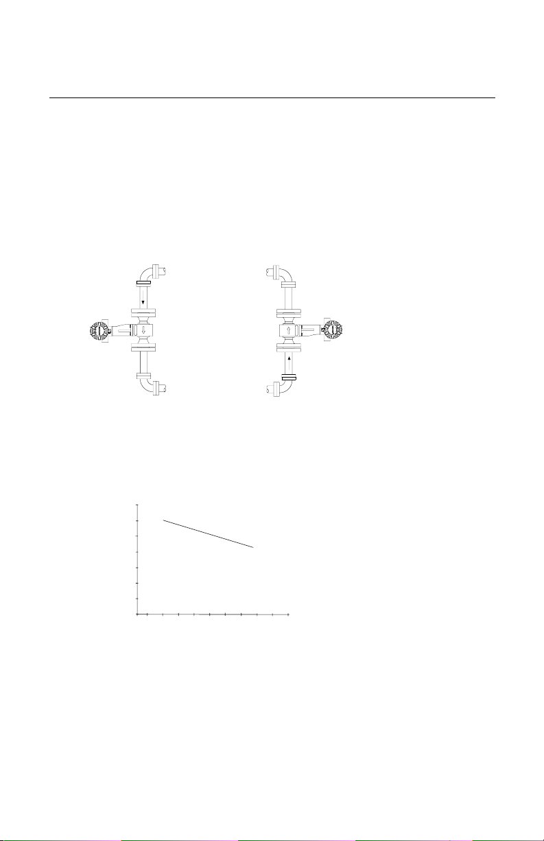
Vertical Mounting
If the vortex flowmeter will be installed in a vertical orientation:
• Install upward or downward flow for gas or steam.
• Install upward flow for liquids.
Figure 1. Vertical Installation
Gas Flow
High Temperature Mounting
The maximum temperature for integral electronics is dependent on the ambient temperature
where the flowmeter is installed. The electronics must not exceed 185°F (85°C).
Figure 2 shows combinations of ambient and process temperatures needed to maintain a
housing temperature of less than 185°F (85°C).
Figure 2. Model 8800C Ambient/Process Temperature Limits
200 (93)
180 (82)
160 (71)
140 (60)
120 (49)
100 (38)
80 (27)
60 (16)
Ambient Temperature °F (°C)
0
185°F Housing
Temperature
Limit
Liquid or Gas
Flow
8800/8800B15B.eps
200 (93)
100 (38)
Meter and pipe insulated with 3 inches of ceramic fiber insulation.
Horizontal Pipe and Vertical meter position.
400 (204)
300 (149)
Process Temperature °F (°C)
600 (316)
500 (260)
700 (371)
800 (427)
900 (482)
1000 (538)
8800_26aa.eps
3
Quick Installation Guide
d
00825-0100-4003, Rev BA
Rosemount 8800C
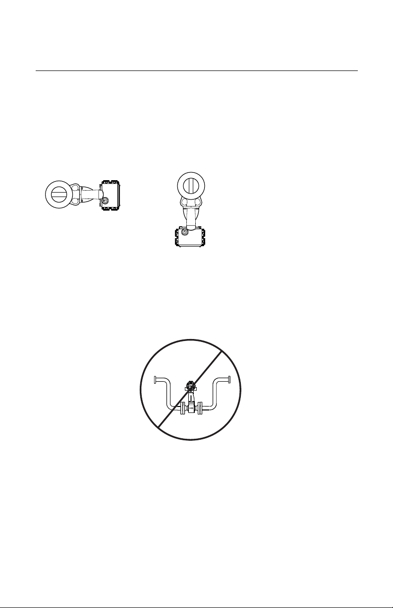
The following orientations are recommended for applications with high process
temperatures.
• Install with meter body beside or below process pipe.
• Insulation around pipe may be necessary to maintain ambient temperature below 185°F
(85°C).
NOTE
Insulate pipe and meter body only. Do not insulate support tube bracket so heat can be
dissipated.
Figure 3. High Temperature Installation
The meter body installe
with the electronics
The meter body installed
with the electronics to
the side of the pipe
For steam and fluids with small solids content, it is recommended to have the flowmeter
installed with the electronics to the side of the pipe. This will minimize potential
measurement errors by allowing the condensate or solids to flow under the shedder bar
without interrupting the vortex shedding.
below the pipe
February 2004
Steam Installations
Avoid installation shown Figure 4. Such conditions may cause a water-hammer condition at
startup due to trapped condensation.
Figure 4. Improper Installation
8800g15c
Upstream/Downstream Requirements
The Model 8800C Flowmeter may be installed with a minimum of ten straight pipe diameters
(D) upstream and five straight pipe diameters (D) downstream by following the K-factor
corrections as described in the Model 8800C Installation Effects Technical Data Sheet
(00816-0100-3250). No K-factor correction is required if 35 straight pipe diameters upstream
(35D) and 10 straight pipe diameters downstream (10D) are available.
When using pressure and temperature transmitters in conjunction with the Model 8800C for
compensated mass flows install the transmitters downstream of the Model 8800C flowmeter
as shown in Figure 5.
4
Quick Installation Guide
00825-0100-4003, Rev BA
February 2004
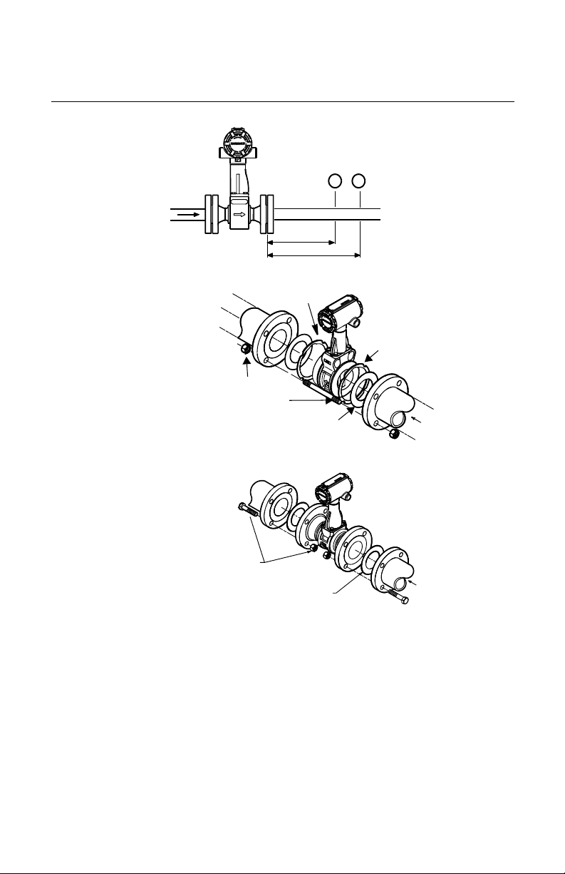
Figure 5. Upstream/Downstream Piping
4 Downstream
6 Downstream
Install Wafer Style Flowmeters according to Figure 6.
Figure 6. Wafer Style Installation
Install Flanged-Style Flowmeters according to Figure 7.
Figure 7. Flanged-Style Flowmeter Installation
Alignment Ring
Installation
Studs and
Nuts (Supplied
by Customer)
Gaskets
(Supplied by
Customer)
Rosemount 8800C
P
T
8800g15a
Alignment
Ring
Flow
8800-0465A01d.eps
Installation Bolts
and Nuts (Supplied
by Customer)
(Supplied by Customer)
NOTE
Gaskets
Flow
8800-065A02B
The required bolt load for sealing the gasket joint is affected by several factors, including
operating pressure and gasket material, width, and condition. A number of factors also
affect the actual bolt load resulting from a measured torque, including condition of bolt
threads, friction between the nut head and the flange, and parallelism of the flanges. Due to
these application-dependent factors, the required torque for each application may be
different. Follow the guidelines outlined in the ASME Pressure Vessel Code (Section VIII,
Division 2) for proper bolt tightening. Make sure the flowmeter is centered between flanges
of the same nominal size as the flowmeter.
5
Quick Installation Guide
00825-0100-4003, Rev BA
Rosemount 8800C
February 2004
Remote Electronics
If you order one of the remote electronics options (options R10, R20, R30, or RXX), the
flowmeter assembly ships in two parts:
1. The meter body with an adapter installed in the support tube and an interconnecting
coaxial cable attached to it.
2. The electronics housing installed on a mounting bracket.
Mounting
Mount the meter body in the process flow line as described earlier in this section. Mount the
bracket and electronics housing in the desired location. The housing can be repositioned on
the bracket to facilitate field wiring and conduit routing.
Cable Connections
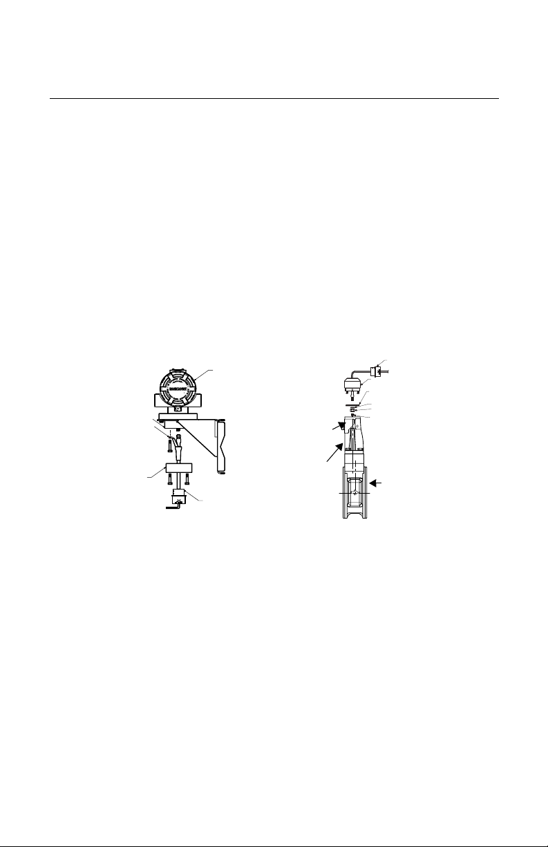
Refer to Figure 8 and the instructions on page 7 to connect the loose end of the coaxial
cable to the electronics housing.
Figure 8. Remote Electronics Installation
Optional ½–14
Electronics
Housing
Housing
Base
Ground
Connection
Housing
Adapter
Coaxial
Cable
* Access Cover is available only in 6 inch (DN50) and 8 inch (DN 200) wafer style flowmeters.
Mounting
Bracket for
Wall or
2-Inch Pipe
Optional ½–14 NPT
Conduit Adapter
or Cable Gland *
Access
Cover *
Support
Tube
NPT Conduit
Adapter or
Cable Gland *
Meter Adapter
Insulating Disk
Washer
Nut
Sensor
Connection
Meter
Body
6
 Loading...