


Quick Start Guide
00825-0300-2654, Rev GB
March 2021
Rosemount™ Volume 1 Sensor Assembly

Quick Start Guide March 2021
Contents
About this guide...........................................................................................................................3
Wiring diagrams...........................................................................................................................4
Rosemount Series 58C sheath cutting ......................................................................................... 6
Drawings......................................................................................................................................7
Rosemount Series 68 Platinum RTD........................................................................................... 10
Rosemount Series 78 Platinum RTD........................................................................................... 12
Rosemount Series 183 Thermocouple........................................................................................15
Rosemount Series 68Q Sanitary Platinum RTD ...........................................................................18
Rosemount Series 58C Platinum RTD......................................................................................... 20
Product certifications................................................................................................................. 21
2 Emerson.com/Rosemount
March 2021 Quick Start Guide
1 About this guide
This guide provides basic guidelines for Sensor models. It does not provide
instructions for configuration, diagnostics, maintenance, service,
troubleshooting, explosion-proof, flameproof, or intrinsically safe (I.S.)
installations. If the Rosemount Volume 1 Sensor was ordered assembled to a
temperature transmitter, see the appropriate transmitter Quick Start Guide
for information on configuration and hazardous locations certifications.
WARNING
Physical access
Unauthorized personnel may potentially cause significant damage to and/or
misconfiguration of end users’ equipment. This could be intentional or
unintentional and needs to be protected against.
Physical security is an important part of any security program and
fundamental to protecting your system. Restrict physical access by
unauthorized personnel to protect end users’ assets. This is true for all
systems used within the facility.
CAUTION
Refer to Product Certification section of this Quick Start Guide
documentation.
Quick Start Guide 3
A
A
B
B
B
B
A
C
C
D
Quick Start Guide March 2021
2 Wiring diagrams
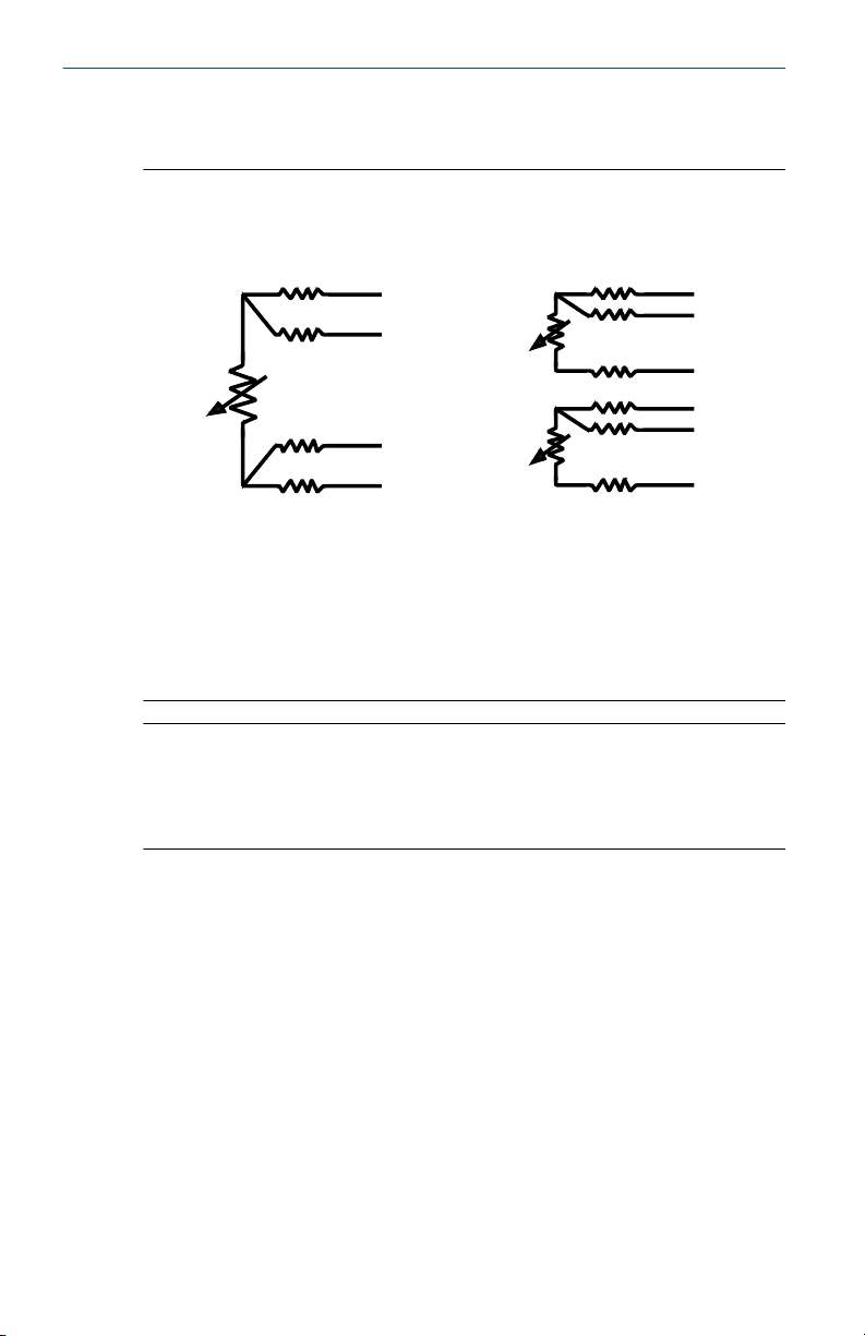
Figure 2-1: Rosemount Series 68, 68Q, 78, and 58C RTD Wire Colors
Single Element Dual Element
(1) Dual element sensors are only available on Rosemount Series 68Q and 78
Sensors.
A. Red
B. White
C. Green
D. Black
(1)
Note
For three-wire systems, use one white and two red leads. Do not connect the
white leads. Insulate or terminate the unused white lead in a manner that
prevents shorting to the ground. For two-wire systems, connect both sets of
leads.
4 Emerson.com/Rosemount

+ A
- B
+ C
- B
+ D
- B
+ E
- B
March 2021 Quick Start Guide
Figure 2-2: Rosemount Series 183 Thermocouple Wire Colors
Type J Type E
Type K Type T
A. White
B. Red
C. Purple
D. Yellow
E. Blue
Note
To distinguish the two sensors in dual Rosemount 183 Sensors, there is an
outer insulation wrapped around each pair of sensor wires.
Quick Start Guide 5

Quick Start Guide March 2021
3 Rosemount Series 58C sheath cutting
Procedure
1. Determine the length to which the sheath will be cut. The finished
length needs to include an additional 1.5-in. (3.8 cm) for
compression fittings or 2.5-in. (6.5 cm) for spring-loaded fittings (see
Figure 4-1).
2. Remove and save the heat shrink tubing from the rear of the sensor.
3. Place the sensor in a vise, taking care not to overtighten, and position
the tubing cutter on the sheath.
4. Score the sheath to a depth of approximately 1/64-in. (0.4 cm) To
prevent damage to the lead wire insulation, do not cut completely
through the sheath.
5. Firmly grasp the end of the sheath with your hand or a pair of pliers.
Using a sharp snapping motion, break off and remove the excess
sheath material. Take care not to strip or damage the lead wire
insulation while removing the excess sheath material.
Note
If you are unable to easily break off excess sheath material, deepen
the score and repeat Step 5.
6. Replace the heat shrink tubing.
6 Emerson.com/Rosemount
A
B
C
D
E
F
March 2021 Quick Start Guide
4 Drawings
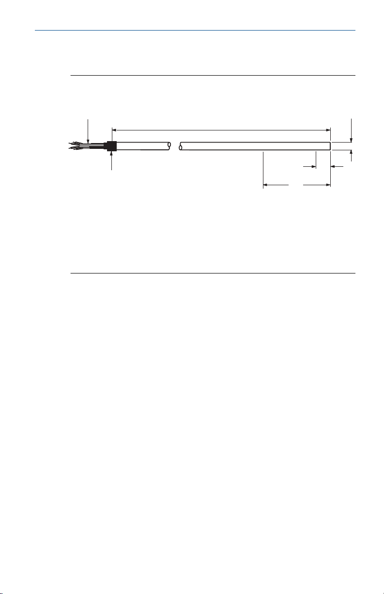
Figure 4-1: Rosemount Series 58C Sensor
A. Four lead wires 6-in. (152 mm) long.
B. X length ±0.25 (±6)
C. 0.25 ±0.002 (6.35 ±0.13) diameter
D. Heat shrink tubing
E. Do not cut or bend sheath within 2-in. (51 mm)
F. 0.6-in. (15 mm) max. sensing element
Quick Start Guide 7
A
B
D
C
E
F
I
G
H
K
J
L
M
O
N
P
Q
R
S
T
Quick Start Guide March 2021
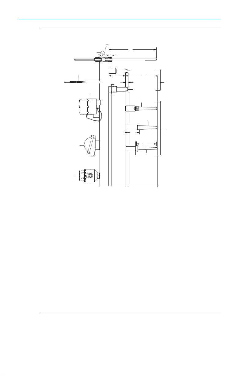
Figure 4-2: Sensor Assembly
A
Open identification tag
B
Standard adapter sensor assembly
C
Sensor immersion length “X”
D
0.5-in. (13 mm) nominal
engagement
E
F
G
H
I
J
8 Emerson.com/Rosemount
Coupling nipple
Extension length
Overall thermowell length
Lead wire extensions and seals
0.5-in. (13 mm) nominal
engagement
Extensions
K
Union nipple
L
Flat or extended cover aluminum
connection heads
M
Threaded thermowell
N
Thermowells
O
T + 1.75-in. (44.5 mm)
P
Socket weld thermowell
Q
Polypropylene connection head
R
Thermowell immersion length
S
Flanged thermowell
T
Rosemount aluminum connection
head

March 2021 Quick Start Guide
Note
Sensor assemblies can be provided without an enclosure or with an
enclosure such as the connection heads shown above or assembled to a
Rosemount transmitter.
Quick Start Guide 9

Quick Start Guide March 2021
5 Rosemount Series 68 Platinum RTD
5.1 Specifications
5.1.1 Performance specifications
Temperature range
–50 to 400 °C (–58 to 752 °F)
Effect of temperature cycling
±0.05 percent (0.13 °C or 0.23 °F) maximum ice-point resistance shift
following 10 cycles over the specified temperature range
Stability
±0.11 percent 0.28 °C or 0.51 °F maximum ice-point resistance shift
following 1,000 hours at maximum specified temperature (400 °C)
Maximum hysteresis
±0.1 percent of operating temperature range
Time constant
12 seconds maximum required to reach 63.2 percent sensor response in
water flowing at 3 ft/s (0.91 m/s)
Nominal R0 100 Ohm
Nominal alpha 0.00385 Ω/Ω °C
5.1.2 Physical specifications
Material selection
Emerson provides a variety of Rosemount product with various product
options and configurations including materials of construction that can be
expected to perform well in a wide range of applications. The Rosemount
product information presented is intended as a guide for the purchaser to
make an appropriate selection for the application. It is the purchaser’s sole
responsibility to make a careful analysis of all process parameters (such as all
chemical components, temperature, pressure, flow rate, abrasives,
contaminants, etc.), when specifying product, materials, options and
components for the particular application. Emerson is not in a position to
evaluate or guarantee the compatibility of the process fluid or other process
parameters with the product, options, configuration or materials of
construction selected.
Sheath material
316 SST and 321 SST
10 Emerson.com/Rosemount
 Loading...