

Quick Start Guide
D-7010-0061, Rev C
January 2018
Rosemount CT5400 Continuous Gas Analyzer


Safety Information
All authorized users, including installation, operation, and maintenance personnel, must observe the following safety precautions
and warnings.
DANGER!
ELECTRIC SHOCK
The analyzer operates using mains voltage that is dangerous to life. Make sure that the power ON/OFF switch at the rear of the panel
is set to OFF and tagged off before removing the top cover.
The analyzer must be earthed.
Death or personal injury may result if this is not observed.
DANGER!
FAILURE TO LOCK-OUT GAS HANDLING SYSTEM MAY CAUSE DEATH.
Always lock out the gas handling system when shutting down the analyzer. Unauthorized operation of the gas handling system
when maintenance is being performed on the analyzer or its associated pipes/hoses may result in highly flammable gas being
released, causing fire or explosion.
DANGER!
FAILURE TO VENT SAMPLE GAS MAY CAUSE DEATH.
The sample gas in the system must be vented to prevent fire or explosion during maintenance and to prevent damage to the
analyzer during startup.
The sample gas in the pipes leading to the analyzer must be purged to prevent hazards to personnel during maintenance. Purging
the sample gas must be done in accordance with the safe working procedures for the site.
Allow the analyzer and system for returning the sample gas to run for five minutes to allow any sample gas in the system to be
returned to the exhaust.
WARNING!
ELECTRICAL SHOCK HAZARD
Do not operate without covers secure.
Do not open while energized.
Installation requires access to live parts which can cause death or serious injury.
For safety and proper performance, this instrument must be connected to a properly grounded three-wire source of power.

WARNING!
OPTICAL RADIATION EXPOSURE HAZARD
The analyzer contains lasers. Opening the analyzer and attempting to perform adjustments or procedures other than those specified
in this manual may result in hazardous optical radiation exposure.
All lasers used within the analyzer are Class 1. The emitted laser light is invisible (mid-infrared) and the combined laser powers are
sufficiently low at the first accessible aperture that the unprotected eye will not be damaged. This class is eye safe under all
operating conditions.
It is, however, possible to cause damage to the eye through not following correct procedures. Do not look at the laser with any kind
of magnifier or optical measuring device.
The use of control or adjustments or performance of procedures other than those specified herein may result in hazardous radiation
exposure.
WARNING!
HAZARDOUS SUBSTANCES
The analyzer may contain hazardous substances. Always handle the analyzer assemblies and components with extreme caution.
Gas handling components within the analyzer will contain particulate matter residue from the sample gases. Over the life of the
analyzer, the concentration of particulate matter will become enriched within the gas handling components. When performing
repairs and maintenance on the analyzer:
• Handle used gas handling components with extreme caution.
• Avoid direct skin contact with used gas handling components.
• Do not smoke, drink, or eat in the work area.
• Wear goggles or eye shields.
• Wear a suitable face mask to protect against inhalation of particulate matter.
• Do not wet fingers, eyes, or any exposed skin.
• Pack used gas handling components for disposal in sealed packaging and label them Contaminated.
Dispose of contaminated items as hazardous material according to the applicable local, national, or international health and safety
regulations and pollution regulations.
WARNING!
EXPLOSION HAZARD
Always lock-out tag-out the gas handling system when shutting down the analyzer. Unauthorized operation of the gas handling
system when maintenance is being performed on the analyzer or its associated pipes/hoses may result in highly flammable gas being
released, causing fire or explosion.
WARNING!
HEAVY ITEM
Handle the analyzer with caution during unpacking, installing, maintaining, and transporting to prevent crushing of hands, feet, or
other body parts.
The analyzer weighs 31 kg (68 lb). Always use suitable lifting/moving equipment when moving the analyzer. Wear suitable
protective gloves and protective footwear.
Failure to properly handle the analyzer may cause injury to personnel.
WARNING!
HAZARDOUS GAS
The product stream that the analyzer is examining may be hazardous even at low concentrations. Therefore, take special care to
ensure that the sample gas return port either returns the sample gas to the product stream or discharges the sample gas to a
location that will not cause a hazard.
WARNING!
HIGH PRESSURE GAS AND AIR
The calibration gas supply and compressed air supply operate at a pressure that can cause injury, e.g., damage to eyes and skin
punctures from debris blown by the high pressure gas or compressed air.
Always lock out or tag off the calibration gas supply and compressed air supply when shutting down the .
WARNING!
EXPLOSION HAZARD
The sample gas in the system must be vented to prevent fire or explosion during maintenance and to prevent damage to the
analyzer during startup.
The sample gas in the pipes leading to the analyzer must be purged to prevent hazards to personnel during maintenance. Purging
the sample gas must be done in accordance with the safe working procedures for the site.
Allow the analyzer and system for returning the sample gas to run for five minutes to allow any sample gas in the system to be
returned to the exhaust.
WARNING!
EXPLOSION
Danger of explosion if battery is incorrectly replaced. Replace only with the same or equivalent type.
CAUTION!
EQUIPMENT DAMAGE
Always follow the startup procedure. Damage to the may result from a failure to follow this procedure.
Failure to perform pre-system startup checks may cause damage to equipment.
CAUTION!
EQUIPMENT DAMAGE
Always follow the shutdown procedure. Damage to the analyzer may result from a failure to follow this procedure.
CAUTION!
EMC
This is a Class A product. In a domestic environment, this product may cause radio interference, in which case you may be required to
take adequate measures.
CAUTION!
EQUIPMENT DAMAGE
Ensure that the local power voltage where the unit is to be installed corresponds to the unit’s nominal voltage as given on the name
plate label.

CAUTION!
EQUIPMENT DAMAGE
Do not power up or try to operate the analyzer unless it is physically secure and all electrical and pneumatic connections to the
analyzer are in place.
Before commencing the start-up process, it is important to ensure that electrical power, sample gas handling facilities, and any
calibration gases that are required are available to the analyzer.

Contents
Contents
Chapter 1 Plan ..................................................................................................................................1
1.1 Unpacking the analyzer .................................................................................................................. 1
1.2 Rack mounting the analyzer ........................................................................................................... 2
1.2.1 Tools required ................................................................................................................. 3
1.3 Detailed system specifications ....................................................................................................... 4
Chapter 2 Install ...............................................................................................................................9
2.1 System overview ............................................................................................................................ 9
2.2 Gas inputs and outputs ................................................................................................................ 10
2.3 Connecting the electrical/electronic inputs and outputs .............................................................. 12
Chapter 3 Navigating the CT5400 Controls ..................................................................................... 15
3.1 Front panel controls and indicators .............................................................................................. 15
3.2 Rear panel controls .......................................................................................................................16
3.3 Display controller ......................................................................................................................... 17
3.4 Gas Sensor Main screen ................................................................................................................18
3.5 Pressure and Temperature screen ................................................................................................ 19
3.6 Help system ................................................................................................................................. 19
3.7 Main menu ...................................................................................................................................20
3.8 BACK button ................................................................................................................................ 21
Chapter 4 Startup procedure ..........................................................................................................23
4.1 Introduction .................................................................................................................................23
4.2 Preparation for use .......................................................................................................................23
4.3 Startup procedure ........................................................................................................................24
i

Contents
ii

1 Plan
1.1 Unpacking the analyzer
This procedure may require a minimum of two people to safely remove the equipment
from the shipping container.
WARNING!
HEAVY ITEM
Handle the analyzer with caution during unpacking, installing, maintaining, and transporting
to prevent crushing of hands, feet, or other body parts.
The analyzer weighs 31 kg (68 lb). Emerson™ recommends that the analyzer is only moved and
lifted by a minimum of two people. Wear suitable protective gloves and protective footwear.
Failure to properly handle the analyzer may cause injury to personnel.
Plan
WARNING!
TRANSPORTATION HAZARD
Use safety-approved lifting equipment. You must ensure safe lifting procedures for the weight
and mass of the equipment are followed.
Failure to use proper lifting procedures may cause injury to personnel or damage the analyzer.
Procedure
1. Visually inspect the exterior of the analyzer for signs of damage, corrosion, gas
leaks, or signs of previously overheating.
2. Report anything found to the maintenance organization.
3. safety approved and tested lifting equipment to remove the analyzer from the
shipping container.
4. Place the analyzer on a solid, level surface and prepare to mount the analyzer.
1
Plan
1.2 Rack mounting the analyzer
This procedure may require two people to safely move and rack mount the Rosemount
CT5400.
WARNING!
HEAVY ITEM
Handle the analyzer with caution during unpacking, installing, maintaining, and transporting
to prevent crushing of hands, feet, or other body parts.
The analyzer weighs 31 kg (68 lb). Emerson™ recommends that the analyzer is only moved and
lifted by a minimum of two people. Wear suitable protective gloves and protective footwear.
Failure to properly handle the analyzer may cause injury to personnel.
Note
You must supply the rack.
Procedure
1. One person aligns the analyzer's telescoping slide rails on the unit as the other
person carefully guides the analyzer into the rack using the front panel and rear
handles (see Figure 1-1).
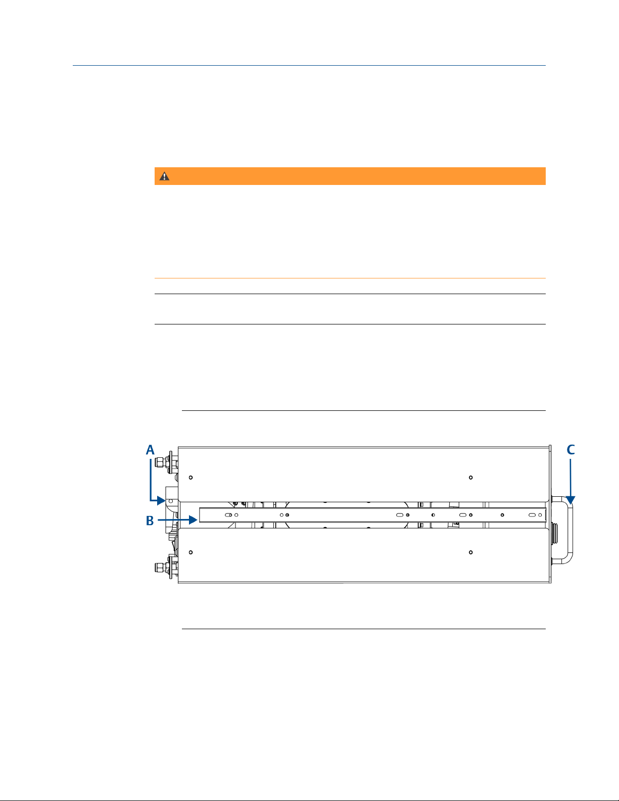
Left Side View - Lifting Handles and Telescopic Slide RailsFigure 1-1:
A. Rear panel handle
B. Telescopic slide for rack mount units
C. Front panel handles
2. Make sure the chassis ventilation holes in the front, top, rear, and bottom are not
obstructed.
2
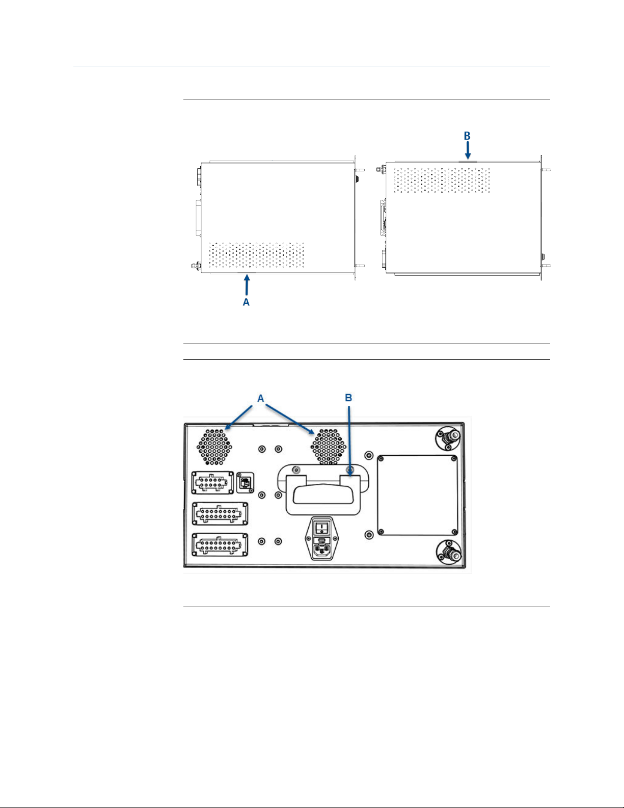
Top and Bottom View - VentilationFigure 1-2:
A. Top ventilation holes
B. Bottom ventilation holes
Plan
Rear View - Ventilation and HandleFigure 1-3:
A. Rear ventilation holes
B. Rear panel handle
3. Inspect the analyzer and ensure the unit is correctly mounted in the rack and glides
easily on the telescoping slide rails.
The analyzer must slide in and out of the rack to make the power, analog, digital,
Ethernet, and gas connections.
1.2.1
Tools required
3
 Loading...