

Rosemount Quick Start Guide: Rosemount™ 628 Wireless Gas Monitor Sensor Module Manuals & Guides
Quick Start Guide
00825-0100-4628, Rev AC
December 2019
Rosemount™ 628 Universal Gas Sensor
Integrated Wireless Gas Monitoring

Quick Start Guide December 2019
Safety information
The United States has two toll-free assistance numbers and one international number.
Customer Central: 1 800 999 9307 (7:00 a.m. to 7:00 p.m. Central Time)
National Reponse Center: 1 800 654 7768 (24 hours a day) for equipment service needs
International: 1 952 906 8888
NOTICE
This guide provides configuration and basic installation information for the Rosemount 628. It does
not provide diagnostic, maintenance, service, troubleshooting, Intrinsically Safe (I.S.) installation, or
ordering information. Refer to the Rosemount 928 Wireless Gas Monitor Reference Manual for more
information.
The manual and this guide are also available electronically on Emerson.com/Rosemount.
NOTICE
Read this document before working with the product. For personal and system safety, and for
optimum product performance, make sure you thoroughly understand the contents before installing,
using, or maintaining this product. For technical assistance, contacts are listed below:
Customer Central
Technical support, quoting, and order-related questions.
United States - 1-800-999-9307 (7:00 am to 7:00 pm Central Time)
Asia Pacific- 65 777 8211
Europe/Middle East/Africa - 49 (8153) 9390
North American Response Center
Equipment service needs.
1-800-654-7768 (24 hours—includes Canada)
Outside of these areas, contact your local Emerson representative.
WARNING
Explosions
Explosions could result in death or serious injury.
Installation of device in an explosive environment must be in accordance with appropriate local,
national, and international standards, codes, and practices.
Before connecting a handheld communication device in an explosive atmosphere, ensure the
instruments are installed in accordance with Intrinsically Safe or non-incendive field wiring
practices.
WARNING
Electrical shock
Electrical shock could cause death or serious injury.
Substitution of components may impair intrinsic safety.
2 Emerson.com/Rosemount

December 2019 Quick Start Guide
WARNING
Physical access
Unauthorized personnel may potentially cause significant damage to and/or misconfiguration of end
users’ equipment. This could be intentional or unintentional and needs to be protected against.
Physical security is an important part of any security program and fundamental to protecting your
system. Restrict physical access by unauthorized personnel to protect end users’ assets. This is true for
all systems used within the facility.
CAUTION
Nuclear applications
The products described in this document are not designed for nuclear qualified applications. Using
non-nuclear qualified products in applications that require nuclear-qualified hardware or products may
cause inaccurate readings.
For information on Rosemount nuclear-qualified products, contact an Emerson sales representative.
Contents
Overview......................................................................................................................................5
Install the sensor.......................................................................................................................... 7
Bench configuration...................................................................................................................10
Guided setup..............................................................................................................................12
Calibrating the sensor................................................................................................................ 21
Verify operating atmosphere..................................................................................................... 43
Quick Start Guide 3

Quick Start Guide December 2019
4 Emerson.com/Rosemount

December 2019 Quick Start Guide
1 Overview
The Rosemount™ 628 is compatible with the Rosemount 928 Wireless Gas
Monitor.
The sensor fits integrally into the transmitter without the use of tools. Make
electrical connections when the sensor module is fully seated in the
transmitter sensor housing.
Note
Use Rosemount 628 only with the Rosemount 928 Transmitter.
CAUTION
The Ingress Protection (IP) filter must be installed.
If the IP filter is not installed, damage may occur to the sensor inside the
Rosemount 628.
Do not operate the transmitter without the correct IP filter installed in
the sensor module.
When installing the IP filter, verify that the IP filter gasket is in place, is
properly aligned, and that it does not block the white filter media. Refer
to Figure 1-1.
When handling the IP filter, avoid contact with the filter media.
Verify that all three legs are fully latched by pushing upward on each leg
of the IP filter.
Avoid getting water inside the IP filter.
Do not attempt to clean the IP filter.
Do not rinse or spray the IP filter with water.
Do not immerse the IP filter in water.
Quick Start Guide 5

Quick Start Guide December 2019
Figure 1-1: IP Filter
A. IP filter housing
B. IP filter gasket
C. Filter media
6 Emerson.com/Rosemount

December 2019 Quick Start Guide
2 Install the sensor
The sensor is held in place using a tight-fitting seal and snap connections.
The sensor is connected to the transmitter by two latching tabs that fit into
the bottom portion of the housing as shown in the figure below. The seal
between the transmitter housing and the sensor assembly is designed so
that a snug, airtight fit is achieved between the two assemblies when
properly installed.
Procedure
1. Remove the sensor from its packaging.
2. If installing a sensor on the transmitter for the first time, remove the
protective plastic cap from the sensor housing at the bottom of the
transmitter.
3. The sensor contains a keying feature that ensures that it cannot be
forced into the transmitter housing in an incorrect alignment.
Confirm that the keying feature is aligned by rotating it into position
before installing the module into the transmitter.
4. Slide the sensor assembly up into the transmitter housing until it is
completely seated.
Quick Start Guide 7
Quick Start Guide December 2019
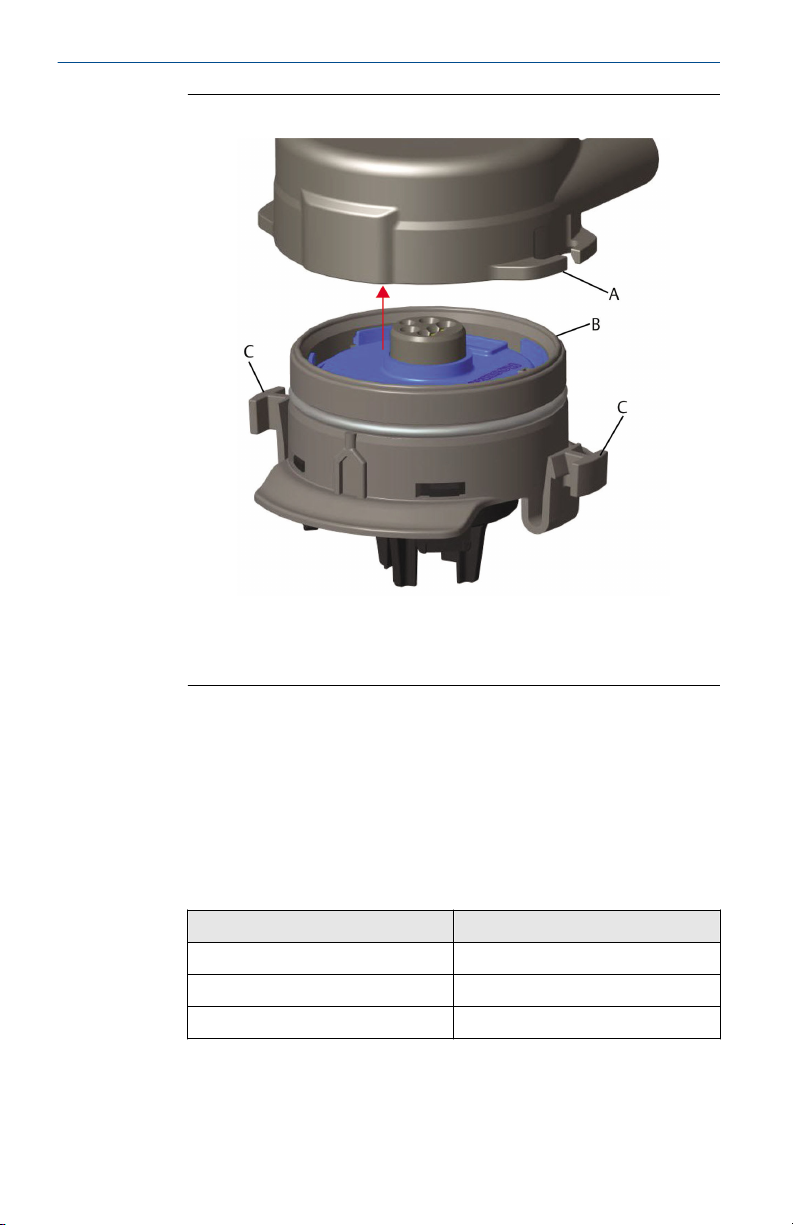
Figure 2-1: Inserting the Sensor into the Transmitter
A. Rosemount 928 Transmitter housing
B. Rosemount 628 Universal Gas Sensor
C. Latching tabs
5. To ensure a firm latch and seal, push the module upward until the
two latching tabs are fully engaged. Push up on the bottoms of the
latching tabs after they are seated.
6. Allow the trannsmitter to warm up before continuing.
Refer to the following table for maximum warm up times based on
gas type. During the warm up period, the displayed values, alerts,
and gas concentrations will not reflect actual measurements;
readings will not be transmitted.
Gas type
Hydrogen sulfide (H2S) One minute
Oxygen (O2) Seven minutes
Carbon monoxide (CO) One minute
8 Emerson.com/Rosemount
Maximum warm up period

December 2019 Quick Start Guide
Postrequisites
To remove the sensor, compress the latching tabs and pull downward until it
is released from the transmitter housing.
Quick Start Guide 9

Quick Start Guide December 2019
3 Bench configuration
To configure, you must install the sensor in a functional transmitter. The
transmitter receives any HART® communication from a handheld Field
Communicator or from an AMS Wireless Configurator.
Remove the rear housing cover to expose the terminal block and HART
communication terminals; then connect the power module to power the
device for configuration.
3.1 Bench configure using a Field Communicator
A transmitter Device Description (DD) is required for HART
communication.
To connect to the transmitter using a handheld communication device, refer
to Guided setup. To obtain the latest DD, go to EmersonProcess.com/
DeviceFiles and then visit the Emerson web page for your handheld device.
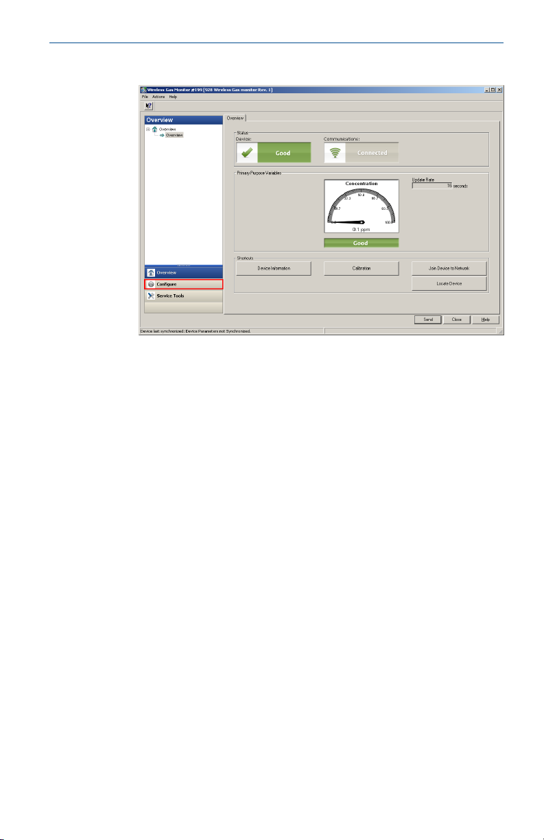
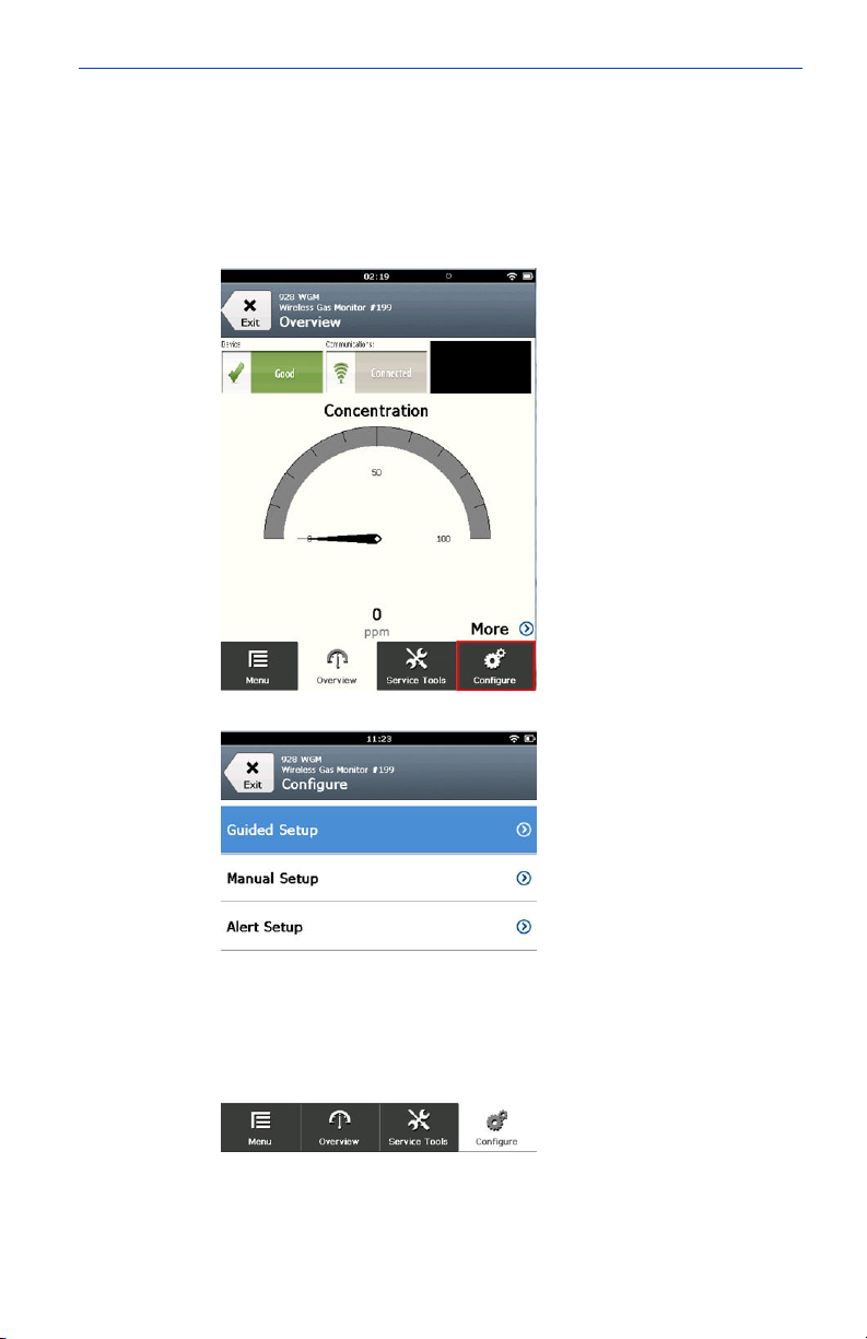
Procedure
1. On the Home screen, select Configure.
2. Do one of the following:
• On the Configure screen, select Guided Setup to verify or change
initial configuration settings. Refer to Guided setup. Refer to the
Field Communicator subsections for each configuration task.
• On the Configure screen, select Manual Setup to verify or change
all configuration settings, including optional advanced settings.
Refer to the Manual Setup section in the Rosemount 928 Wireless
Gas Monitor Reference Manual. Refer to the Field Communicator
subsections for each configuration task.
®
3. When finished, select Send to implement configuration changes.
4. When configuration is completed, remove the HART
communications leads from the COMM terminals on the terminal
block and replace the rear housing cover.
3.2
10 Emerson.com/Rosemount
Bench configure AMS Wireless Configurator
AMS Wireless Configurator is capable of connecting to devices directly,
using a HART® modem, or though a Wireless Gateway.
Procedure
1. In the AMS Device Manager pane, select the HART modem.
2. In the device pane, double-click the device icon.
December 2019 Quick Start Guide
3. Select Configure.
4. In the Configure pane, do one of the following:
• Select Guided Setup to verify or change initial configuration
settings. Refer to Guided setup. Refer to the AMS Wireless
Configurator subsections for each configuration task.
• Select Manual Setup to verify or change all configuration settings,
including optional advanced settings. Refer to the Manual Setup
section in the Rosemount 928 Wireless Gas Monitor Reference
Manual. Refer to the AMS Wireless Configurator subsections for
each configuration task.
5. When finished, select Send to implement configuration changes.
Quick Start Guide 11
Quick Start Guide December 2019
4 Guided setup
Guided setup contains basic configurations settings. The Guided Setup
menus are useful during initial configuration.
Note
Emerson developed the Field Communicator Guided Setup configuration
procedures using Emerson AMS Trex™ Device Communicator. The menus are
identical to those found in other Field Communicators, but are navigated
using touch screens rather than fast keys. Refer to the manual for your
handheld communicator device for more information.
WARNING
Explosions
Do not connect to the COMM terminals when an explosive atmosphere is
present.
Procedure
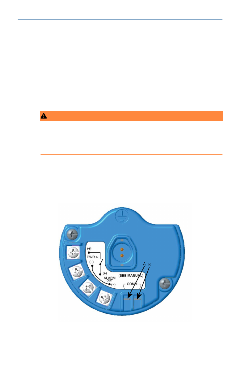
1. Connect the HART® communication leads to the HART terminals on
the handheld communicator.
2. Connect the HART communication leads to the COMM terminals on
the transmitter terminal block.
A. +Comm terminal
B. -Comm terminal
12 Emerson.com/Rosemount
December 2019 Quick Start Guide
3. Start your handheld communicator device. If necessary, open the
HART Field Communicator application on your handheld device to
establish HART communication.
Refer to the manual for your handheld communicator device for
more information.
4. On the Overview screen, select Configure.
5. On the Configure screen, select Guided Setup.
Postrequisites
Refer to Basic setup throughConfiguring process alerts.
Quick Start Guide 13
Quick Start Guide December 2019
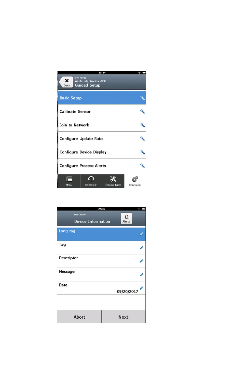
4.1 Basic setup
4.1.1 Basic setup using Field Communicator
Procedure
1. On the Guided Setup screen, select Basic Setup.
2. On the Device Information screen, select any of the following and
configure as needed. Otherwise, continue with Step 3.
14 Emerson.com/Rosemount
 Loading...