

Rosemount Quick Start Guide: Rosemount 485 Annubar® Flanged Flo-Tap Assembly Manuals & Guides
Quick Start Guide
00825-0400-4809, Rev FB
Rosemount™ 485 Annubar™ Flanged
Flo-Tap Assembly
June 2016

Quick Start Guide
June 2016
NOTICE
This guide provides basic guidelines for Rosemount 485 Annubar. It does not provide instructions for
configuration, diagnostics, maintenance, service, troubleshooting, Explosion-proof, Flameproof, or
Intrinsically Safe (I.S.) installations. Refer to the Rosemount 485 Annubar Reference Manual
instruction. This manual is also available electronically on Emerso nProcess.com/Rosemount
If the Rosemount Annubar was ordered assembled to a Rosemount Pressure Transmitter, see the following
Quick Start Guides for information on configuration and hazardous locations certifications:
Rosemount 3051S Series Pressure Transmitter and Rosemount 3051SF Series Flowmeter Quick Start
Guide.
Rosemount 3051S MultiVariable Transmitter and Rosemount 3051SF Series Flowmeter MultiVariable
Tra ns mi tte r Quick Start Guide
Rosemount 3051 Pressure Transmitter and Rosemount 3051CF Series Flowmeter Transmitter Quick
Start Guide.
Rosemount 2051 Pressure Transmitter and Rosemount 2051CF Series Flowmeter Transmitter Quick
Start Guide.
Process leaks may cause harm or result in death. To avoid process leaks, only use gaskets designed to seal
with the corresponding flange and O-rings to seal process connections. Flowing medium may cause the
Rosemount 485 Annubar Assembly to become hot and could result in burns.
.
for more
.
Contents
Location and orientation . . . . . . . . . . . . . . . . . 4
Weld mounting hardware . . . . . . . . . . . . . . . .8
Install isolation valve . . . . . . . . . . . . . . . . . . . . .9
Mount drilling machine and drill hole . . . . .10
Remove drilling machine . . . . . . . . . . . . . . . .10
2
Mount the Rosemount Annubar Assembly . . . .11
Insert the Rosemount Annubar Sensor . . . . . . . 12
Mount the Transmitter . . . . . . . . . . . . . . . . . . . . . 13
Retracting the Rosemount Annubar Assembly 17
Product certifications . . . . . . . . . . . . . . . . . . . . . 18
June 2016
Quick Start Guide
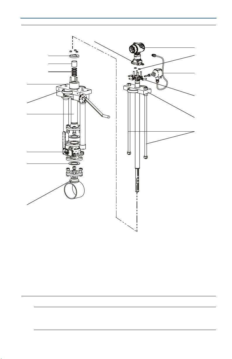
Figure 1. Rosemount 485 Annubar Flanged Flo-Tap Assembly Exploded View
P
A
O
B
N
M
C
L
D
K
J
I
H
G
A. Transmitter
B. 2⫻ O-rings J. Cage nipple
C. Temperature sensor connection housing K. Support plate
D. Direct mount transmitter connection with valves L. Packing gland
E. Head plate M. Packing
F. Drive rods N. Follower
G. Mounting flange assembly O. Compression plate
H. Gasket P. Coplanar flange with drain vents
I. Isolation valve
E
F
Note
Use an appropriate pipe sealing compound rated for the service temperature on all
threaded connections.
3
Quick Start Guide
1.0 Location and orientation
Correct orientation and straight run requirements must be met for accurate and
repeatable flow measurements. Refer to Table 1for minimum pipe diameter
distances from upstream disturbances.
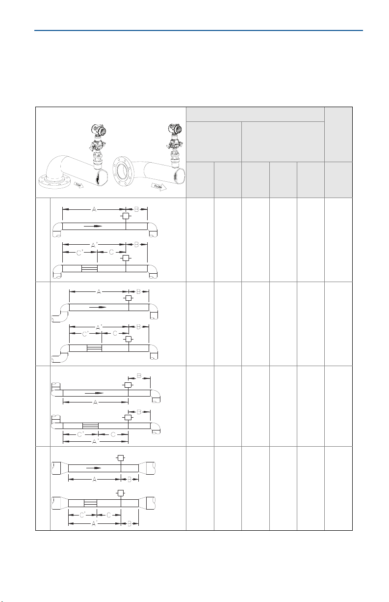
Table 1. Straight Run Requirements
In plane____________Out of plane Upstream pipe diameters
June 2016
Without
straightening
vanes
In
Out of
plane
plane
A
8
1
N/A10N/A
11
2
N/A16N/A
23
3
With straightening
vanes
A’ C C’ B
A
N/A8N/A4N/A
N/A8N/A4N/A
N/A8N/A4N/A
Downstream
pipe diameters
4
4
4
4
4
4
4
N/A28N/A
12
4
N/A12N/A
N/A8N/A4N/A
4
4
4
4
4
4
June 2016
Quick Start Guide
18
5
N/A18N/A
30
6
N/A30N/A
N/A8N/A4N/A
4
N/A8N/A4N/A
4
Note
Consult the factory for instructions regarding use in square or rectangular
ducts.
“In plane A” means the bar is in the same plane as the elbow. “Out of plane A”
means the bar is perpendicular to the plane of the elbow.
If proper lengths of straight run are not available, position the mounting such
that 80% of the run is upstream and 20% is downstream.
Use straightening vanes to reduce the required straight run length.
Row 6 in Ta bl e 1 applies to gate, globe, plug, and other throttling valves that
are partially opened, as well as control valves.
4
4
4
4
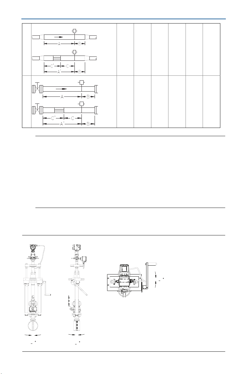
1.1 Misalignment
Rosemount 485 Annubar installation allows for a maximum misalignment of 3°.
Figure 2. Misalignment
+
3
+
3
+
3
5

Quick Start Guide
Recommended zone
30
1.2 Horizontal orientation
For proper venting and draining, the sensor should be located in the upper half of
the pipe for air and gas applications. For liquid and steam applications, the sensor
should be located in the bottom half of the pipe. The maximum temperature for a
direct mounted transmitter is 500 °F (260 °C). See “Install isolation valve” on
page 9 for remote mounted transmitter recommendations.
Figure 3. Gas
Recommended zone
30
s
June 2016
Figure 4. Liquid and Steam
Note
For steam applications with DP readings between 0.75 and 2 inH2O in horizontal pipes, it is
recommended to install the primary element/flowmeter mounting above the pipe.
6
June 2016
360
Flow
360
Flow
Quick Start Guide
Note
Due to the weight of the Flo-Tap mounting hardware, external support may be needed for
vertical orientation applications and horizontal orientation applications that are installed
outside of the recommended zones.
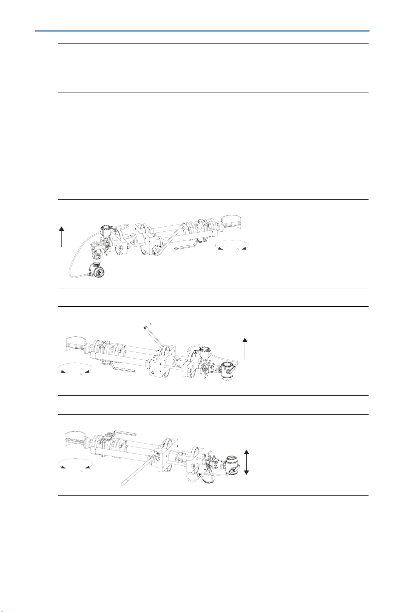
1.3 Vertical orientation
The sensor can be installed in any position around the circumference of the pipe,
provided the vents are positioned properly for bleeding or venting. Optimal
results for liquid or steam are obtained when flow is up. For steam applications, a
90° spacer will be added to provide water legs to ensure the transmitter stays
within temperature limits. The maximum temperature for a direct mounted
transmitter is 500 °F (260 °C).
Figure 5. Steam
Figure 6. Liquid
Figure 7. Gas
360
Flow
7

Quick Start Guide
June 2016
2.0 Weld mounting hardware
Note
Rosemount-supplied mounting has an integral alignment built into the mounting hardware
that assists in the correct drilling of the mounting hole. It also assists in the alignment of the
sensor to the mounting hole for insertion.
1. At the pre-determined position, place the flanged assembly on the pipe, gap
1
/16-in. (1.6 mm), and measure the distance from the outer diameter of the
pipe to the face of the flange. Compare this toTa b le 2 and adjust the gap as
necessary.
Table 2. Flange Sizes and Outer Diameter to Flange (ODF) per Sensor Size
Sensor size Flange size ODF (in. [mm]) Flange size ODF (in. [mm])
1 11/2-in. 150# 3.88 (98,5) DN40 PN16 3.09 (78,6)
1 11/2-in. 300# 4.13 (104,9) DN40 PN40 3.21 (81,6)
1 11/2-in. 600# 4.44 (112,7) DN40 PN100 3.88 (98,6)
1 11/2-in. 900# 4.94 (125,4) N/A N/A
1 11/2-in. 1500# 4.94 (125,4) N/A N/A
1 11/2-in. 2500# 6.76 (171,6) N/A N/A
2 2.0-in. 150# 4.13 (104,8) DN50 PN16 3.40 (86,3)
2 2.0-in. 300# 4.38 (111,2) DN50 PN40 3.51 (89,3)
2 2.0-in. 600# 4.76 (120,8) DN50 PN100 4.30 (109,3)
2 2.0-in. 900# 5.88 (149,2) N/A N/A
2 2.0-in. 1500# 5.88 (149,2) N/A N/A
2 3.0-in. 2500# 9.87 (250,7) N/A N/A
3 3.0-in. 150# 4.63 (117,5) DN80 PN16 3.84 (97,6)
3 3.0-in. 300# 5.00 (126,9) DN80 PN40 4.16 (105,6)
3 3.0-in. 600# 5.38 (136,6) DN80 PN100 4.95 (125,6)
3 4.0-in. 900# 8.19 (208,0) N/A N/A
3 4.0-in. 1500# 8.56 (217,5) N/A N/A
3 4.0-in. 2500# 11.19 (284,2) N/A N/A
8
 Loading...