

Quick Start Guide: Rosemount 4088A MultiVariable™ Transmitter with Modbus® Output Protocol
Table of contents
 Loading...
Rosemount Quick Start Guide: Rosemount 4088A MultiVariable™ Transmitter with Modbus® Output Protocol Manuals & Guides

Quick Start Guide
00825-0100-4088, Rev CA
April 2019
Rosemount™4088A MultiVariable
Transmitter
with Modbus® Output Protocol
™

Quick Start Guide April 2019
Safety messages
NOTICE
This guide provides basic guidelines for the Rosemount 4088 MultiVariable Transmitter. It does not
provide instructions for diagnostics, maintenance, service, or troubleshooting. Reference the 4088
MultiVariable Transmitter Reference Manual for more instruction. All documents are available
electronically at Emerson.com/Rosemount.
Procedures and instructions in this section may require special precautions to ensure the safety of the
personnel performing the operation. Information that raises potential safety issues is indicated with a
warning symbol ( ). Refer to the following safety messages before performing an operation
preceded by this symbol.
WARNING
Explosions could result in death or serious injury.
Installation of this transmitter in an explosive environment must be in accordance with the
appropriate local, national, and international standards, codes, and practices. Review the
approvals section of the 4088 MultiVariable Transmitter Reference Manual for any restrictions
associated with a safe installation.
• Before connecting a Field Communicator in an explosive atmosphere, ensure the instruments
in the loop are installed in accordance with intrinsically safe or non-incendive field wiring
practices.
•
In an Explosion-proof/Flameproof installation, do not remove the transmitter covers when
power is applied to the unit.
Process leaks may cause harm or result in death.
Install and tighten process connectors before applying pressure.
Electrical shock can result in death or serious injury.
Avoid contact with the leads and terminals. High voltage that may be present on leads can cause
electrical shock.
Conduit/cable entries
• Unless marked, the conduit/cable entries in the transmitter housing use a 1/2–14 NPT thread
form. Entries marked “M20” are M20 x 1.5 thread form. On devices with multiple conduit
entries, all entries will have the same thread form. Only use plugs, adapters, glands, or
conduit with a compatible thread form when closing these entries.
• When installing in a hazardous location, use only appropriately listed or Ex certified plugs,
adapters, or glands in cable/conduit entries.
Contents
Steps required for quick installation............... 3
Mount the transmitter................................... 4
Consider housing rotation............................11
Set the switches........................................... 13
2 Rosemount 4088A MultiVariable Transmitter Quick Start Guide
Wiring and power up ...................................14
Verify device configuration.......................... 21
Trim the transmitter.................................... 25
Product certifications...................................27

April 2019 Quick Start Guide
1 Steps required for quick installation
• Start >
• Mount the transmitter: Mount the Transmitter
• Consider housing rotation: Consider Housing Rotation
• Set the switches: Set the Switches
• Wiring and power up : Wiring and Power Up
• Verify device configuration: Verify Device Configuration
• Trim the transmitter: Trim the Transmitter
• > Finish
Quick Start Guide 3

A
A
Quick Start Guide April 2019
2 Mount the transmitter
2.1 Liquid flow applications
Procedure
1. Place taps to the side of the line.
2. Mount beside or below the taps.
3. Mount the transmitter so that the drain/vent valves are oriented
upward.
A. Direction of flow
2.2 Gas flow applications
Procedure
1. Place taps in the top or side of the line.
2. Mount beside or above the taps.
A. Direction of flow
4 Rosemount 4088A MultiVariable Transmitter Quick Start Guide

A
April 2019 Quick Start Guide
2.3 Steam flow applications
Procedure
1. Place taps to the side of the line.
2. Mount beside or below the taps.
3. Fill impulse lines with water.
A. Direction of flow
2.4 Mounting brackets
Figure 2-1: Mounting Bracket – Coplanar Flange
Panel mount
Quick Start Guide 5
Pipe mount

Quick Start Guide April 2019
Figure 2-2: Mounting Brackets – Traditional Flange
Panel mount Pipe mount
Figure 2-3: Mounting Brackets – In-line
Panel mount Pipe mount
2.5 Bolting considerations
If the transmitter installation requires assembly of a process flange,
manifold, or flange adapters, follow these assembly guidelines to ensure a
tight seal for optimal performance characteristics of the transmitter. Only
use bolts supplied with the transmitter or sold by Emerson™ as spare parts.
Figure 2-4 illustrates common transmitter assemblies with the bolt length
required for proper transmitter assembly.
6 Rosemount 4088A MultiVariable Transmitter Quick Start Guide

A
4 × 1.75-in.
(44 mm)
D
4 × 1.75-in.
(44 mm)
4 × 2.25-in.
(57 mm)
C
4 × 1.75-in.
(44 mm)
4
× 1.50-in.
(38 mm)
B
4 × 2.88-in.
(73 mm)
April 2019 Quick Start Guide
Figure 2-4: Common Transmitter Assemblies
A. Transmitter with coplanar flange
B. Transmitter with coplanar flange and optional flange adapters
C. Transmitter with traditional flange and optional flange adapters
D. Transmitter with coplanar flange and optional Rosemount Conventional
Manifold and flange adapters
Note
For all other manifolds, contact Customer Central technical support.
Bolts are typically carbon steel or stainless steel. Confirm the material by
viewing the markings on the head of the bolt and referencing Table 2-1 . If
bolt material is not shown in Table 2-1, contact the local Emerson
representative for more information.
Use the following bolt installation procedure:
Procedure
1. Carbon steel bolts do not require lubrication and the stainless steel
bolts are coated with a lubricant to ease installation. However, no
additional lubricant should be applied when installing either type of
bolt.
2. Finger-tighten the bolts.
3. Torque the bolts to the initial torque value using a crossing pattern.
See Table 2-1 for initial torque value.
4. Torque the bolts to the final torque value using the same crossing
pattern. See Table 2-1 for final torque value.
Quick Start Guide 7

B7M
316
316
316
SW
316
STM
316
R
B8M
A
B
Quick Start Guide April 2019
5. Verify the flange bolts are protruding through the sensor module
before applying pressure (see Figure 2-5).
Example
Table 2-1: Torque Values for the Flange and Flange Adapter Bolts
Bolt material Head markings Initial torque Final torque
Carbon Steel
300 in-lb 650 in-lb
(CS)
Stainless Steel
150 in-lb 300 in-lb
(SST)
Figure 2-5: Proper Bolt Installation
A. Bolt
B. Sensor module
8 Rosemount 4088A MultiVariable Transmitter Quick Start Guide

A
B
C
D
April 2019 Quick Start Guide
2.6 O-rings with flange adapters
WARNING
Failure to install proper flange adapter O-rings may cause process leaks,
which can result in death or serious injury. Only use the O-ring that is
designed for its specific flange adapter.
A. Flange adapter
B. O-ring
C. PTFE-based profile (square)
D. Elastomer profile (round)
Whenever the flange or adapters are removed, visually inspect the O-rings.
Replace them if there are any signs of damage, such as nicks or cuts. If the Orings are replaced, re-torque the flange bolts and alignment screws after
installation to compensate for seating of the O-rings.
2.7 Environmental seal for housing
Thread sealing (PTFE) tape or paste on male threads of conduit is required to
provide a water/dust tight conduit seal and meets requirements of NEMA
Type 4X, IP66, and IP68. Consult factory if other Ingress Protection ratings
are required. For M20 threads, install conduit plugs to full thread
engagement or until mechanical resistance is met.
2.8
Quick Start Guide 9
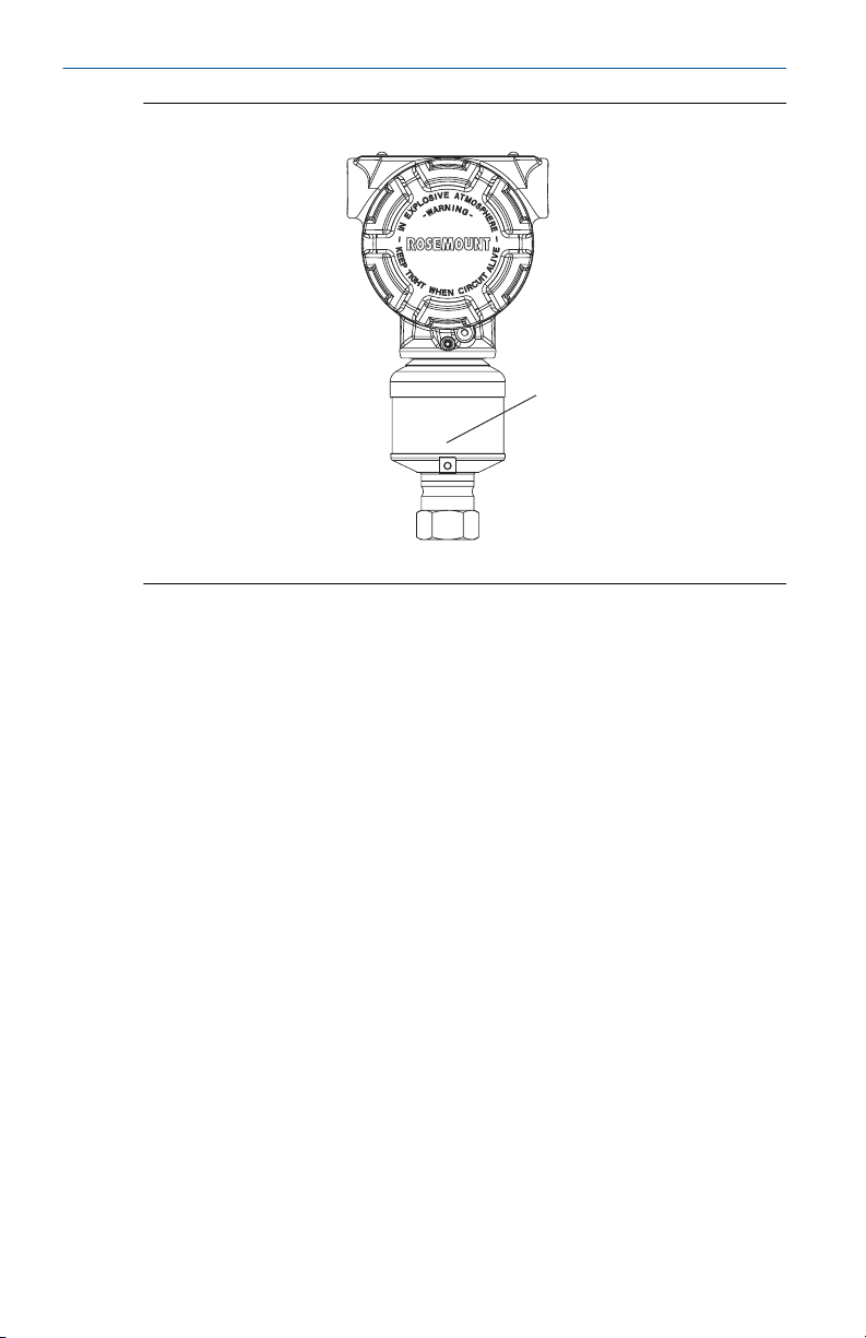
In-line gage transmitter orientation
The low side pressure port (atmospheric reference) on the in-line gage
transmitter is located under the sensor module neck label. (See Figure 2-6)
Keep the vent path free of any obstruction, including but not limited to
paint, dust, and lubrication by mounting the transmitter so that any
contaminants can drain away.
®
A
Quick Start Guide April 2019
Figure 2-6: In-line Gage Transmitter
A. Low side pressure port (under neck label)
10 Rosemount 4088A MultiVariable Transmitter Quick Start Guide

April 2019 Quick Start Guide
3 Consider housing rotation
To improve field access to wiring or to better view the optional LCD display:
Procedure
1. Loosen the housing rotation set screw.
2. Turn the housing up to 180° left or right of its original (as shipped)
position.
3. Re-tighten the housing rotation set screw.
Figure 3-1: Transmitter Housing Set Screw
A. LCD display
B. Housing rotation set screw (3/32-in.)
CAUTION
Do not rotate the housing more than 180° without first performing a
disassembly procedure. Over-rotation may sever the electrical
connection between the sensor module and the electronics.
3.1
Quick Start Guide 11
Rotate the LCD display
Transmitters ordered with the LCD display will be shipped with the display
installed.
In addition to housing rotation, the optional LCD display can be rotated in
90° increments by squeezing the two tabs, pulling out, rotating and
snapping back into place.
If LCD display pins are inadvertently removed from the electronics board,
carefully re-insert the pins before snapping the LCD display back into place.
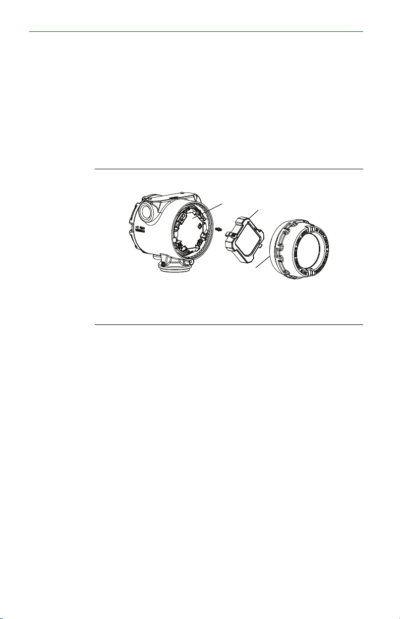
Use the following procedure and Figure 3-2 to install the LCD display:
Procedure
1. If the transmitter is installed in a loop, then secure the loop and
disconnect power.
B
C
A
Quick Start Guide April 2019
2. Required: Remove the transmitter cover on the electronics board
side (opposite the field terminals side). Do not remove instrument
covers in explosive environments when circuit is live.
3. Engage the four-pin connector into the electronics board and snap
LCD display into place.
4. Required: In order to meet explosion-proof requirements, reinstall
the housing cover and tighten so the cover is fully seated with metal
to metal contact between the housing and cover. After the cover is
seated properly, replace the flathead screw located on the bottom of
the housing cover.
Figure 3-2: Optional LCD Display
A. Electronics board
B. LCD display
C. Display cover
12 Rosemount 4088A MultiVariable Transmitter Quick Start Guide
A B
April 2019 Quick Start Guide
4 Set the switches
Procedure
1. If the transmitter is installed, secure the bus and remove power.
2. Required: Remove the transmitter cover opposite the field terminal
side. Do not remove the instrument covers in explosive
environments when the circuit is live.
3. Slide the Security and switches into the preferred position by using a
small screwdriver.
Note
The Security switch will need to be in the off position in order to make
any configuration changes.
4. Required: In order to meet explosion-proof requirements, reinstall
the housing cover and tighten so the cover is fully seated with metal
to metal contact between the housing and cover. After the cover is
seated properly, replace the flathead screw located on the bottom of
the housing cover.
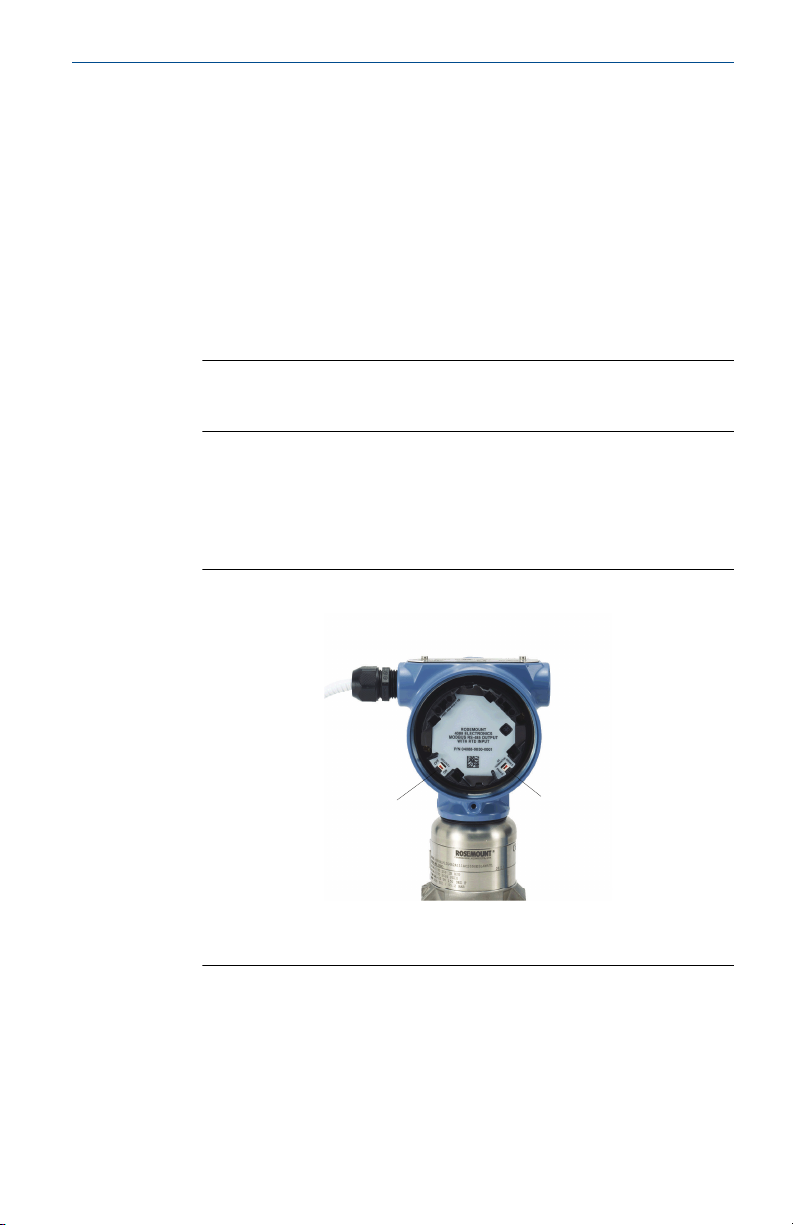
Figure 4-1: Transmitter Switch Configuration
A. Security
B. AC Termination
Quick Start Guide 13

Quick Start Guide April 2019
5 Wiring and power up
Use the following steps to wire the transmitter:
Procedure
1. Remove the cover on the field terminals side of the housing.
2. Set up based on optional process temperature input.
a) If the optional process temperature input is being utilized,
follow the procedure Install optional process temperature
input (Pt 100 RTD Sensor).
b) If there will not be an optional process temperature input,
plug and seal the unused conduit connection.
NOTICE
When the enclosed threaded plug is utilized in the conduit
opening, it must be installed with a minimum engagement of
five threads in order to comply with explosion-proof
requirements. For straight threads, a minimum of six threads
must be engaged. For tapered threads, install the plug
wrench-tight.
3. Connect the Rosemount 4088A to the RS-485 bus as shown in Figure
6-2.
a) Connect the A lead to the “A” terminal.
b) Connect the B lead to the “B” terminal.
4. Connect the positive lead from the power source to the “PWR +”
terminal, and the negative lead to the “PWR –” terminal (for power
requirements, reference ).
Note
The Rosemount 4088A uses RS-485 Modbus® with eight data bits,
one stop bit and no parity. The default baud rate is 9600.
Note
Twisted pair wiring is required for RS-485 bus wiring. Wiring runs
under 1000 ft (305 m) should be AWG 22 or larger. Wiring runs from
1000 to 4000 ft. (305 to 1219 m) should be AWG 20 or larger. Wiring
should not exceed AWG 16.
5. Ensure full contact with terminal block screw and washer. When
using a direct wiring method, wrap wire clockwise to ensure it is in
place when tightening the terminal block screw.
14 Rosemount 4088A MultiVariable Transmitter Quick Start Guide
Loading...