

Quick Start Guide
00825-0100-4811, Rev JF
Rosemount™ 3300 Level Transmitter
Guided Wave Radar
April 2022

Quick Start Guide April 2022
Contents
About this guide...........................................................................................................................3
Mount the transmitter head/probe.............................................................................................. 7
Set jumpers and switches........................................................................................................... 17
Connect wiring and power up.....................................................................................................19
Configure................................................................................................................................... 25
Environmental conditions.......................................................................................................... 31
Product certifications................................................................................................................. 32
2 Rosemount 3300 Level Transmitter

April 2022 Quick Start Guide
1 About this guide
This start guide provides basic guidelines for the Rosemount 3300 Level
Transmitter. Refer to Rosemount 3300 Level Transmitter Reference Manual
for more instructions. The manual and this Quick Start Guide (QSG) are also
available electronically on Emerson.com/Rosemount.
WARNING
Failure to follow safe installation and servicing guidelines could result in
death or serious injury.
• Ensure only qualified personnel perform installation or service.
• Use the equipment only as specified in this Quick Start Guide and the
Reference Manual. Failure to do so may impair the protection provided
by the equipment.
• Do not perform any service other than those contained in this manual
unless you are qualified.
• Flamepath joints are not for repair. Contact the manufacturer.
Explosions could result in death or serious injury.
• Verify that the operating environment of the transmitter is consistent
with the appropriate hazardous locations specifications. See Product
certifications in this Quick Start Guide.
• In an explosion-proof/flameproof installation, do not remove the
transmitter covers when power is applied to the unit.
• Before connecting a handheld communicator in an explosive
atmosphere, ensure the instruments are installed in accordance with
intrinsically safe or non-incendive field wiring practices.
• To avoid process leaks, only use the O-ring designed to seal with the
corresponding flange adapter.
Electrical shock could cause death or serious injury.
• Avoid contact with the leads and terminals. High voltage that may be
present on leads can cause electrical shock.
• Ensure the mains power to the transmitter is off and the lines to any
other external power source are disconnected or not powered while
wiring the transmitter.
Temperature restrictions apply for Explosion-proof versions. For limits, see
certificate-specific information in the Product certifications chapter in this
document.
Quick Start Guide 3

Quick Start Guide April 2022
WARNING
The electronics enclosures are category 2G or 2D equipment. The probes
not covered with plastic and not made of titanium, are category 1G or 1D.
The plastic covered probes or probes made of titanium, are only category 1G
equipment.
Probes with non-conducting surfaces and light metals:
• Probes covered with plastic and/or with plastic discs may generate an
ignition- capable level of electrostatic charge under certain extreme
conditions. Therefore, when the probe is used in a potentially explosive
atmosphere, appropriate measures must be taken to prevent
electrostatic discharge. These probes are not allowed in dust classified
areas.
The following probes do not contain plastic or PTFE material, and are
allowed to be placed in a Dust classified area:
Table 1-1: Probes Containing no Plastic or PTFE Material
Code Material of construction: Process connection/Probe
1 316L SST (EN 1.4404)
2 Alloy C-276 (UNS N10276) plate design if flanged version
3 Alloy 400 (UNS N04400) plate design if flanged version
5 Titanium Gr-1 and Gr-2
9 Duplex 2205 (EN 1.4462/UNS S31803) (plate design if flanged
L Alloy 625 (UNS N06625)
M Alloy 400 (UNS N04400)
H Alloy C-276 (UNS N10276)
D Duplex 2205 (EN 1.4462/UNS S31803)
version)
The Material of Construction Code can be found in the ninth character
position of the transmitter model code (for example
330xxxxx1xxxxxxxx).
4 Rosemount 3300 Level Transmitter
Category 2D
Category 1D
Applicable marking:
Probes according to Table 1-1
Ex tb [ia Da] IIIC T85 °C…T450 °C Db
II 1/2 D Ex ia IIIC T20085 °C…T200450 °C Da /
Category 2G
Category 1G
All probes possible
II 1/2 G Ex ia IIC T6…T1 Ga /
Ex db [ia Ga] IIC T6…T1 Gb
Applicable marking:
Category 2D
Category 2D
Probes according to Table 1-1
Applicable marking:
II 2 D Ex tb IIIC T85 °C…T135 °C Db
April 2022 Quick Start Guide
• Probes and flanges containing >7.5 percent magnesium or zirconium are
not allowed in explosive dust atmosphere. Contact your Emerson sales
representative for more information.
Probes and flanges containing light metals:
• When used in category 1/2G installations, probes and flanges containing
titanium or zirconium must be mounted in such a way that sparks from
impact or friction between these parts and steel cannot occur.
Separation element (EPL Ga/Gb, Da/Db):
• The materials of the separation element are > 3 mm stainless steel and a
22 mm bushing filled with 2-part epoxy. The epoxy has a continuous
operating temperature of -55 °C ≤ COT ≤ 130 °C. Under normal operation
Quick Start Guide 5

Quick Start Guide April 2022
the separation element is not pressurized or in contact with the process
media.
WARNING
Any substitution of non-authorized parts or repair, other than exchanging
the complete transmitter head or probe assembly, may jeopardize safety
and is prohibited.
• Unauthorized changes to the product are strictly prohibited as they may
unintentionally and unpredictably alter performance and jeopardize
safety. Unauthorized changes that interfere with the integrity of the
welds or flanges, such as making additional perforations, compromise
product integrity and safety. Equipment ratings and certifications are no
longer valid on any products that have been damaged or modified
without the prior written permission of Emerson. Any continued use of
product that has been damaged or modified without the written
authorization is at the customer’s sole risk and expense.
WARNING
Physical access
Unauthorized personnel may potentially cause significant damage to and/or
misconfiguration of end users’ equipment. This could be intentional or
unintentional and needs to be protected against.
Physical security is an important part of any security program and
fundamental to protecting your system. Restrict physical access by
unauthorized personnel to protect end users’ assets. This is true for all
systems used within the facility.
6 Rosemount 3300 Level Transmitter
$
April 2022 Quick Start Guide
2 Mount the transmitter head/probe
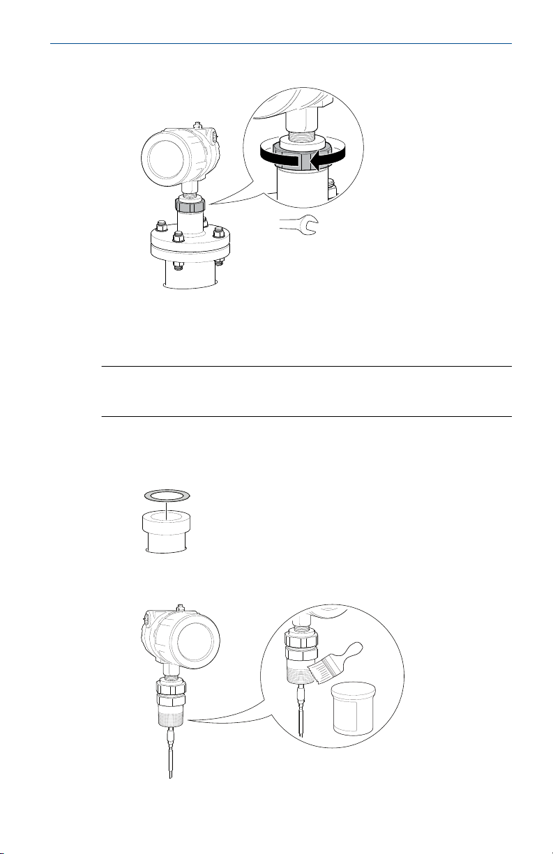
2.1 Tank connection with flange
Prerequisites
Note
PTFE covered probes must be handled carefully to prevent damage to the
coating.
Procedure
1. Place a suitable gasket on top of the tank flange.
Note
Gasket should not be used for PTFE covered probe with protective
plate.
A. PTFE covered probe with protective plate
2. Lower the transmitter and probe with flange into the tank.
Quick Start Guide 7
60 mm
Quick Start Guide April 2022
3. Tighten bolts and nuts with sufficient torque for the flange and
gasket choice.
4. Loosen the nut that connects the transmitter head to the probe
slightly.
5. Rotate the transmitter housing so the cable entries/display face the
desired direction.
8 Rosemount 3300 Level Transmitter
60 mm
Torque 30 ft-lb (40 Nm)
April 2022 Quick Start Guide
6. Tighten the nut.
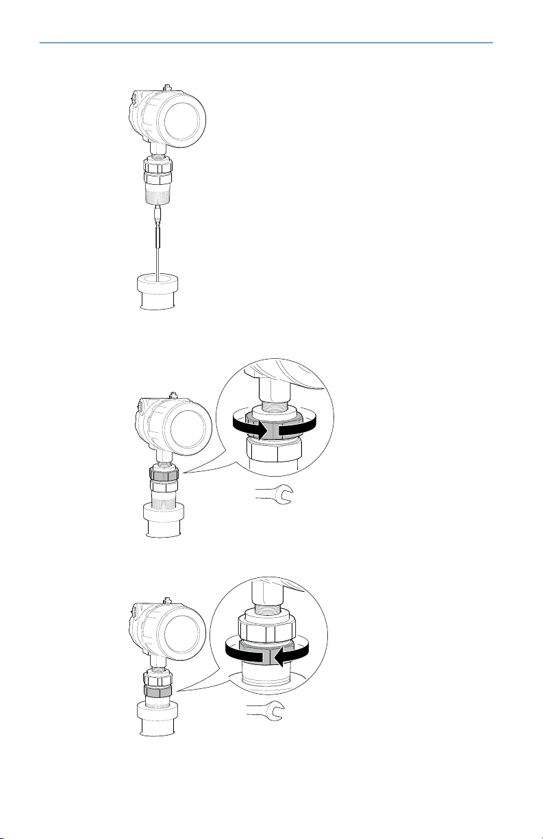
2.2 Threaded tank connection
Prerequisites
Note
PTFE covered probes must be handled carefully to prevent damage to the
coating.
Procedure
1. For adapters with BSPP (G) threads, place a suitable gasket on top of
the tank flange.
2. For adapters with NPT threads, use anti-seize paste or PTFE tape
according to your site procedures.
Quick Start Guide 9
60 mm
52 mm / 60 mm
Quick Start Guide April 2022
3. Lower the transmitter and probe into the tank.
4. Loosen the nut that connects the transmitter head to the probe
slightly.
5. Screw the adapter into the process connection.
10 Rosemount 3300 Level Transmitter

60 mm
Torque 30 ft-lb (40 Nm)
April 2022 Quick Start Guide
6. Rotate the transmitter housing so the cable entries/display face the
desired direction.
7. Tighten the nut.
Quick Start Guide 11
Quick Start Guide April 2022
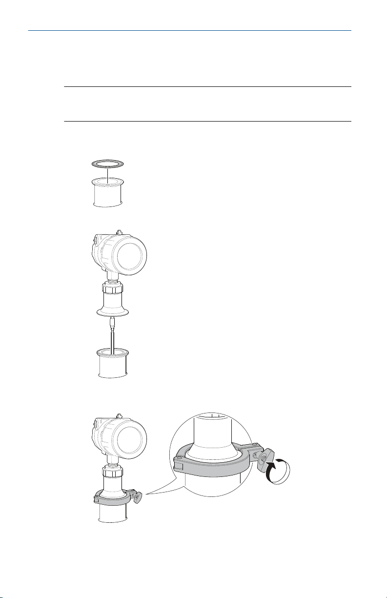
2.3 Tank connection with Tri-Clamp
Prerequisites
Note
PTFE covered probes must be handled carefully to prevent damage to the
coating.
Procedure
1. Place a suitable gasket on top of the tank flange.
2. Lower the transmitter and probe into the tank.
®
3. Tighten the clamp to the recommended torque (see the
manufacturer’s instruction manual).
12 Rosemount 3300 Level Transmitter
60 mm
60 mm
Torque 30 ft-lb (40 Nm)
April 2022 Quick Start Guide
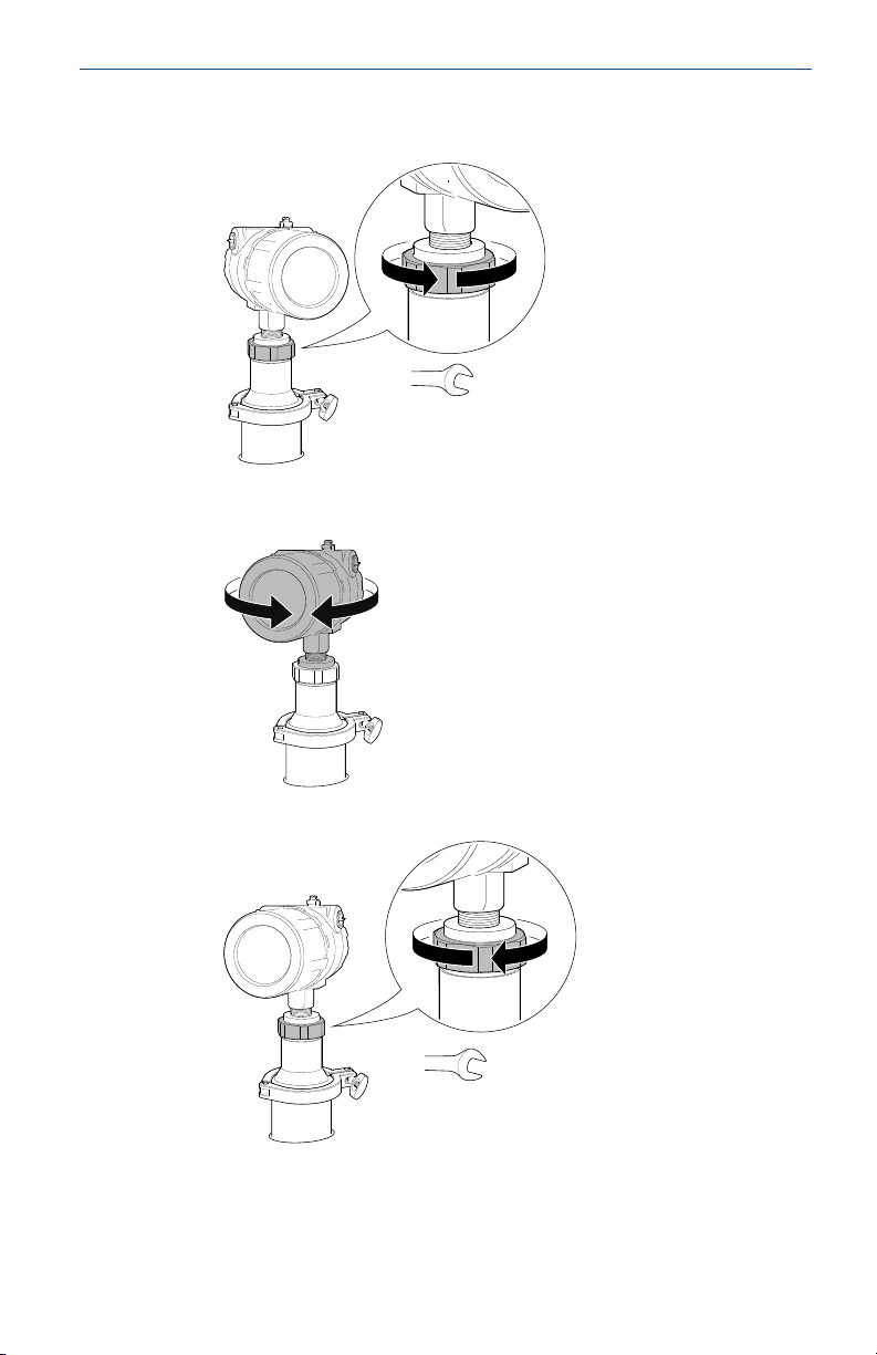
4. Loosen the nut that connects the transmitter head to the probe
slightly.
5. Rotate the transmitter housing so the cable entries/display face the
desired direction.
6. Tighten the nut.
Quick Start Guide 13
4X
A
B
4X
Quick Start Guide April 2022
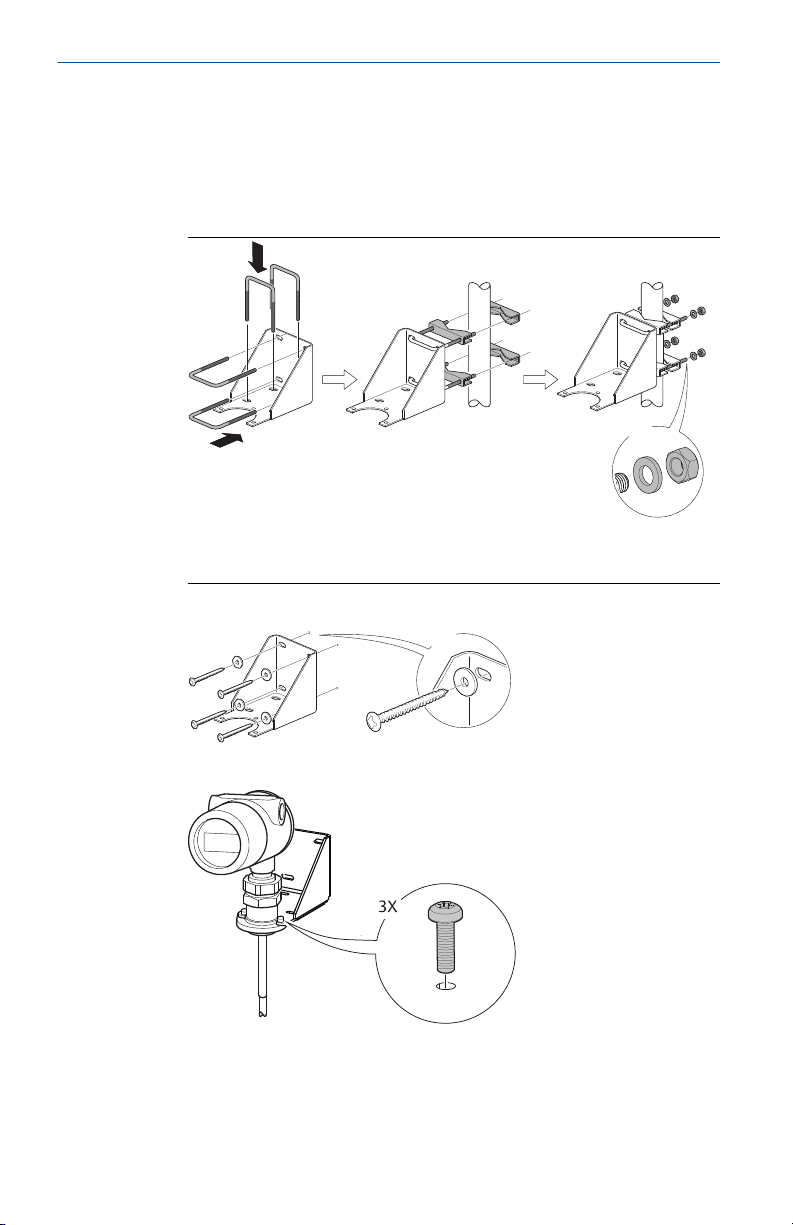
2.4 Bracket mounting
Procedure
1. Mount the bracket to the pipe/wall.
On pipe:
A. Horizontal pipe
B. Vertical pipe
On wall:
2. Mount the transmitter with probe to the bracket.
14 Rosemount 3300 Level Transmitter
$
Torque 30 ft-lb (40 Nm)
55 mm
April 2022 Quick Start Guide
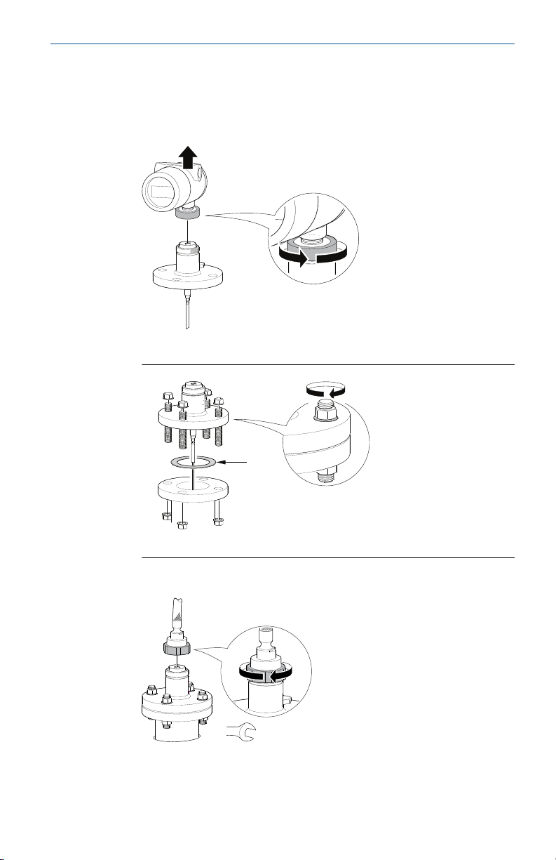
2.5 Install remote housing
Procedure
1. Carefully remove the transmitter.
2. Mount the probe on tank.
A. Gasket
3. Mount the remote connection on the probe.
Quick Start Guide 15

4X
A
B
3X
Torque 30 ft-lb (40 Nm)
Quick Start Guide April 2022
4. Mount the bracket to the pipe.
A. Horizontal pipe
B. Vertical pipe
5. Fasten the housing support.
6. Mount the transmitter head.
16 Rosemount 3300 Level Transmitter
 Loading...