

Quick Start Guide: Rosemount™ 3051S MultiVariable™ Transmitter and 3051SF Series MultiVariable™ Flowmeter with FOUNDATION™ Fieldbus Protocol
Table of contents
 Loading...
Rosemount Quick Start Guide: Rosemount™ 3051S MultiVariable™ Transmitter and 3051SF Series MultiVariable™ Flowmeter with FOUNDATION™ Fieldbus Protocol Manuals & Guides

Quick Start Guide
00825-0100-4853, Rev AG
October 2021
Rosemount™ 3051S MultiVariable
™
Transmitter and 3051SF Series Flow
Meter
with FOUNDATION™ Fieldbus Protocol

Quick Start Guide October 2021
Safety messages
NOTICE
This guide provides basic guidelines for Rosemount™ 3051S MultiVariable™ (3051SMV) FOUNDATION
Fieldbus Transmitters. It does not provide instructions for diagnostics, maintenance, service, or
troubleshooting. Refer to the Rosemount 3051SMV FOUNDATION Fieldbus Reference Manual for more
instruction.This document is also available electronically on Emerson.com/Rosemount.
™
WARNING
Explosions could result in death or serious injury.
Installation of device in an explosive environment must be in accordance with appropriate local,
national, and international standards, codes, and practices.
Review Rosemount 3051SMV FOUNDATION Fieldbus Reference Manual for any restrictions associated
with a safe installation.
• Before connecting a handheld communicator in an explosive atmosphere, ensure that the
instruments in the loop are installed in accordance with intrinsically safe or non-incendive field
wiring practices.
• In an explosion-proof/flameproof installation, do not remove the transmitter covers when power
is applied to the unit.
Process leaks could result in death or serious injury.
• Install and tighten process connectors before applying pressure.
Electrical shock could cause death or serious injury.
• Avoid contact with the leads and terminals. High voltage that may be present on leads can cause
electrical shock.
Conduit/cable entries
• Unless marked, the conduit/cable entries in the housing use a ½–14 NPT thread form. Entries
marked “M20” are M20 × 1.5 thread form. On devices with multiple conduit entries, all entries will
have the same thread form. Only use plugs, adapters, glands, or conduit with a compatible thread
form when closing these entries.
• When installing in a hazardous location, use only appropriately listed or Ex certified plugs, glands,
or adapters in cable/conduit entries.
Contents
Mount the transmitter..................................................................................................................5
Tagging......................................................................................................................................11
Consider housing rotation..........................................................................................................12
Set the switches......................................................................................................................... 14
Wiring, grounding, and power....................................................................................................16
System readiness....................................................................................................................... 21
Zero trim the transmitter........................................................................................................... 22
2 Rosemount 3051SMV

October 2021 Quick Start Guide
Product certifications................................................................................................................. 23
Quick Start Guide 3

Quick Start Guide October 2021
4 Rosemount 3051SMV

A
A
October 2021 Quick Start Guide
1 Mount the transmitter
1.1 Liquid flow applications
Procedure
1. Place taps to the side of the line.
2. Mount beside or below the taps.
3. Mount the transmitter so that the drain/vent valves are oriented
upward.
A. Direction of flow
1.2 Gas flow applications
Procedure
1. Place taps in the top or side of the line.
2. Mount beside or above the taps.
A. Direction of flow
Quick Start Guide 5

A
Quick Start Guide October 2021
1.3 Steam flow applications
Procedure
1. Place taps to the side of the line.
2. Mount beside or below the taps.
3. Fill impulse lines with water.
A. Direction of flow
1.4 Mounting brackets
Figure 1-1: Mounting Bracket – Coplanar Flange
Panel mount
6 Rosemount 3051SMV
Pipe mount

October 2021 Quick Start Guide
Figure 1-2: Mounting Brackets – Traditional Flange
Panel mount Pipe mount
Figure 1-3: Mounting Brackets – In-line
Panel mount Pipe mount
1.5 Bolting considerations
If the transmitter installation requires assembly of a process flange,
manifold, or flange adapters, follow these assembly guidelines to ensure a
tight seal for optimal performance characteristics of the transmitter. Only
use bolts supplied with the transmitter or sold by Emerson as spare parts.
Figure 1-4 illustrates common transmitter assemblies with the bolt length
required for proper transmitter assembly.
Quick Start Guide 7

A
4 × 1.75-in.
(44 mm)
D
4 × 1.75-in.
(44 mm)
4 × 2.25-in.
(57 mm)
C
4 × 1.75-in.
(44 mm)
4
× 1.50-in.
(38 mm)
B
4 × 2.88-in.
(73 mm)
Quick Start Guide October 2021
Figure 1-4: Common Transmitter Assemblies
A. Transmitter with coplanar flange
B. Transmitter with coplanar flange and optional flange adapters
C. Transmitter with traditional flange and optional flange adapters
D. Transmitter with coplanar flange and optional Rosemount Conventional
Manifold and flange adapters
Note
For all other manifolds, contact Customer Central technical support.
Bolts are typically carbon steel or stainless steel. Confirm the material by
viewing the markings on the head of the bolt and referencing Table 1-1 . If
bolt material is not shown in Table 1-1, contact the local Emerson
representative for more information.
Use the following bolt installation procedure:
Procedure
1. Carbon steel bolts do not require lubrication and the stainless steel
bolts are coated with a lubricant to ease installation. However, no
additional lubricant should be applied when installing either type of
bolt.
2. Finger-tighten the bolts.
3. Torque the bolts to the initial torque value using a crossing pattern.
See Table 1-1 for initial torque value.
4. Torque the bolts to the final torque value using the same crossing
pattern. See Table 1-1 for final torque value.
8 Rosemount 3051SMV

B7M
316
316
316
SW
316
STM
316
R
B8M
A
B
October 2021 Quick Start Guide
5. Verify the flange bolts are protruding through the sensor module
before applying pressure (see Figure 1-5).
Example
Table 1-1: Torque Values for the Flange and Flange Adapter Bolts
Bolt material Head markings Initial torque Final torque
Carbon Steel
300 in-lb 650 in-lb
(CS)
Stainless Steel
150 in-lb 300 in-lb
(SST)
Figure 1-5: Proper Bolt Installation
A. Bolt
B. Sensor module
Quick Start Guide 9

A
B
C
D
Quick Start Guide October 2021
1.6 O-rings with flange adapters
WARNING
Failure to install proper flange adapter O-rings may cause process leaks,
which can result in death or serious injury. Only use the O-ring that is
designed for its specific flange adapter.
A. Flange adapter
B. O-ring
C. PTFE-based profile (square)
D. Elastomer profile (round)
Whenever the flange or adapters are removed, visually inspect the O-rings.
Replace them if there are any signs of damage, such as nicks or cuts. If the Orings are replaced, re-torque the flange bolts and alignment screws after
installation to compensate for seating of the O-rings.
10 Rosemount 3051SMV

Commissioning Tag
DEVICE ID:
0011513051010001440-12169809172 5
DEVICE REVISION: 7.2
PHYSICAL DEVICE TAG
DEVICE ID:
0011513051010001440-12169809172 5
DEVICE REVISION: 7.2
S / N :
PHYSICAL DEVICE TAG
Device Barcode
A
Commissioning Tag
DEVICE ID:
001151AC00010001440-1216980917 25
DEVICE REVISION: 8.1
PHYSICAL DEVICE TAG
DEVICE ID:
001151AC00010001440-121698091725
DEVICE REVISION: 8.1
S / N :
PHYSICAL DEVICE TAG
Device Barcode
October 2021 Quick Start Guide
2 Tagging
2.1 Commissioning tag
The transmitter is supplied with a removable commissioning tag that
contains both the Device ID (the unique code that identifies a particular
device in the absence of a device tag) and a space to record the device tag
(PD_TAG) (the operational identification for the device as defined by the
Piping and Instrumentation Diagram [P&ID]).
When commissioning more than one device on a Fieldbus segment, it can be
difficult to identify which device is at a particular location. The removable
tag, provided with the transmitter, can aid in this process by linking the
Device ID to its physical location. The installer should note the physical
location of the transmitter on both the upper and lower location of the
commissioning tag. Tear off the bottom portion for each device on the
segment and use it for commissioning the segment in the control system.
Figure 2-1: Commissioning Tag
Quick Start Guide 11
A. Device revision

Quick Start Guide October 2021
3 Consider housing rotation
To improve field access to wiring or to better view the optional LCD display:
Procedure
1. Loosen the housing rotation set screw.
2. Turn the housing up to 180° left or right of its original (as shipped)
position.
3. Re-tighten the housing rotation set screw.
Figure 3-1: Transmitter Housing Set Screw
A. LCD display
B. Housing rotation set screw (3/32-in.)
CAUTION
Do not rotate the housing more than 180° without first performing a
disassembly procedure. Over-rotation may sever the electrical
connection between the sensor module and the electronics.
3.1
12 Rosemount 3051SMV
Rotate the LCD display
Transmitters ordered with the LCD display will be shipped with the display
installed.
In addition to housing rotation, the optional LCD display can be rotated in
90° increments by squeezing the two tabs, pulling out, rotating and
snapping back into place.
If LCD display pins are inadvertently removed from the electronics board,
carefully re-insert the pins before snapping the LCD display back into place.
Use the following procedure and Figure 3-2 to install the LCD display:
Procedure
1. If the transmitter is installed in a loop, then secure the loop and
disconnect power.

B
C
A
October 2021 Quick Start Guide
2. Required: Remove the transmitter cover on the electronics board
side (opposite the field terminals side). Do not remove instrument
covers in explosive environments when circuit is live.
3. Engage the four-pin connector into the electronics board and snap
LCD display into place.
4. Required: In order to meet explosion-proof requirements, reinstall
the housing cover and tighten so the cover is fully seated with metal
to metal contact between the housing and cover. After the cover is
seated properly, replace the flathead screw located on the bottom of
the housing cover.
Figure 3-2: Optional LCD Display
A. Electronics board
B. LCD display
C. Display cover
Quick Start Guide 13
SECURITY
SIMULATE
ENABLE
DISABLE
C
D
E
F
B
A
Quick Start Guide October 2021
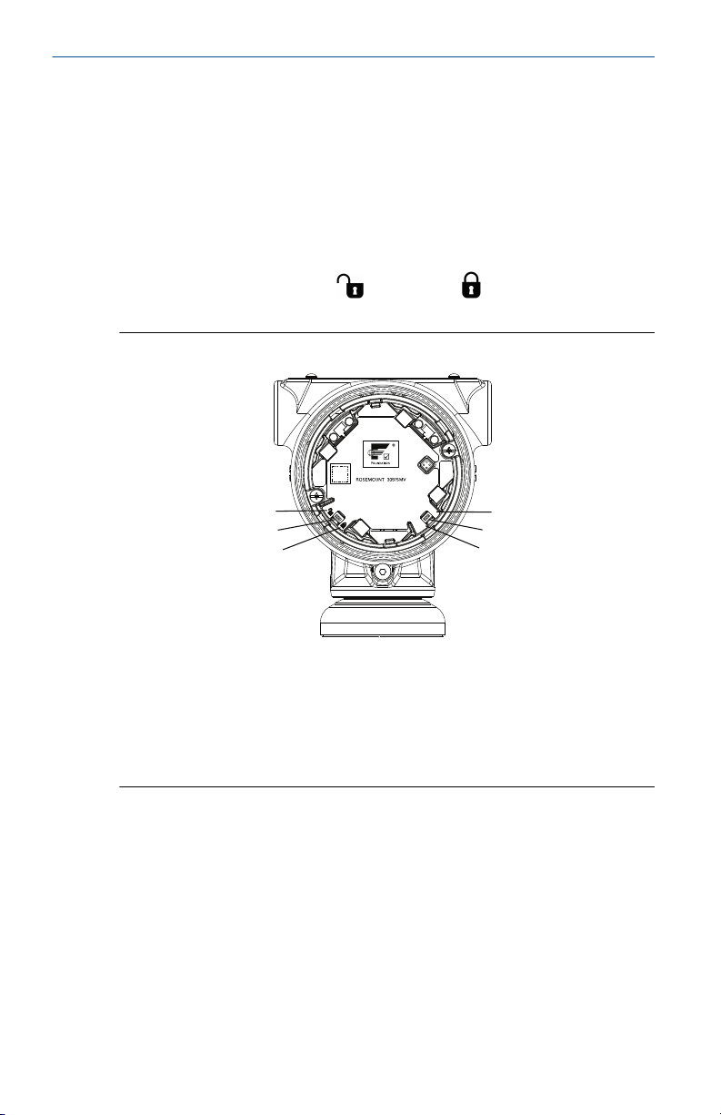
4 Set the switches
Prerequisites
Set Simulate and Security switch position before installation (location of
switches shown in Figure 4-1), as desired.
• The Simulate switch enables or disables the ability to set simulated alerts
or simulated measured value and status.
• The Security switch allows (
) or prevents ( ) any configuration of
the transmitter.
Figure 4-1: Simulate and Security Switches
A. Security unlocked position
B. Security switch
C. Security locked position
D. Simulate disabled position
E. Simulate switch
F. Simulate enabled position
Further security settings are available in the software, including settings
which use a software lock. Additionally, these settings can be used to disable
both hardware and software locks.
Use the following procedure to change the switch configuration:
Procedure
1. If the transmitter is installed, secure the segment, and remove
power.
14 Rosemount 3051SMV
Loading...