

Quick Start Guide: Rosemount 3051S MultiVariable™ Transmitter and 3051SF Series Flowmeter MultiVariable™ Transmitter with HART® Protocol
Table of contents
 Loading...
Rosemount Quick Start Guide: Rosemount 3051S MultiVariable™ Transmitter and 3051SF Series Flowmeter MultiVariable™ Transmitter with HART® Protocol Manuals & Guides

Quick Start Guide
00825-0100-4803, Rev GA
October 2021
Rosemount™ 3051S and 3051SF Series
Flow Meter MultiVariable™ Transmitters

Quick Start Guide October 2021
Contents
About this guide...........................................................................................................................3
Mount the transmitter..................................................................................................................5
Consider housing rotation..........................................................................................................11
Set the switches......................................................................................................................... 12
Connect wiring and power up.....................................................................................................13
Engineering Assistant installation...............................................................................................17
Flow configuration..................................................................................................................... 19
Verifying device configuration....................................................................................................28
Trimming the transmitter...........................................................................................................32
Safety instrumented systems installation................................................................................... 33
Product certifications................................................................................................................. 34
2 Rosemount 3051SMV

October 2021 Quick Start Guide
1 About this guide
This guide provides basic guidelines to install the Rosemount 3051S
MultiVariable Transmitter. It also provides the basic Rosemount 3051SMV
configuration guidelines for the Rosemount 3051SFA, Rosemount 3051SFC,
and Rosemount 3051SFP. It does not provide instructions for detailed
configuration, diagnostics, maintenance, service, troubleshooting, or
installations. Refer to the Rosemount 3051SMV Reference Manual for more
instruction. The manual and this guide are also available electronically at
Emerson.com/Rosemount.
1.1 Safety messages
WARNING
Failure to follow these installation guidelines could result in death or
serious injury.
Ensure only qualified personnel perform the installation.
Explosions
Explosions could result in death or serious injury.
Installation of device in an explosive environment must be in accordance
with appropriate local, national, and international standards, codes, and
practices.
Review the Hazardous Locations Certifications for any restrictions
associated with a safe installation.
Process leaks
Process leaks could result in death or serious injury.
Install and tighten thermowells and sensors before applying pressure.
Do not remove the thermowell while in operation.
Conduit/cable entries
Unless marked, the conduit/cable entries in the transmitter housing use
a ½–14 NPT thread form. Entries marked “M20” are M20 × 1.5 thread
form. On devices with multiple conduit entries, all entries will have the
same thread form. Only use plugs, adapters, glands, or conduit with a
compatible thread form when closing these entries.
When installing in a hazardous location, use only appropriately listed or
Ex certified plugs, glands, or adapters in cable/conduit entries.
Quick Start Guide 3

Quick Start Guide October 2021
WARNING
Electrical shock
Electrical shock could cause death or serious injury.
Avoid contact with the leads and terminals. High voltage that may be
present on leads can cause electrical shock.
Unless marked, the conduit/cable entries in the housing use a ½–14 NPT
thread form. Entries marked “M20” are M20 × 1.5 thread form. On
devices with multiple conduit entries, all entries will have the same
thread form. Only use plugs, adapters, glands, or conduit with a
compatible thread form when closing these entries.
When installing in a hazardous location, use only appropriately listed or
Ex certified plugs, glands, or adapters in cable/conduit entries.
Physical access
Unauthorized personnel may potentially cause significant damage to and/or
misconfiguration of end users’ equipment. This could be intentional or
unintentional and needs to be protected against.
Physical security is an important part of any security program and
fundamental to protecting your system. Restrict physical access by
unauthorized personnel to protect end users’ assets. This is true for all
systems used within the facility.
4 Rosemount 3051SMV
A
A
October 2021 Quick Start Guide
2 Mount the transmitter
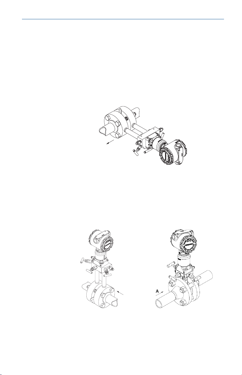
2.1 Liquid flow applications
Procedure
1. Place taps to the side of the line.
2. Mount beside or below the taps.
3. Mount the transmitter so that the drain/vent valves are oriented
upward.
A. Direction of flow
2.2 Gas flow applications
Procedure
1. Place taps in the top or side of the line.
2. Mount beside or above the taps.
A. Direction of flow
Quick Start Guide 5
A
Quick Start Guide October 2021
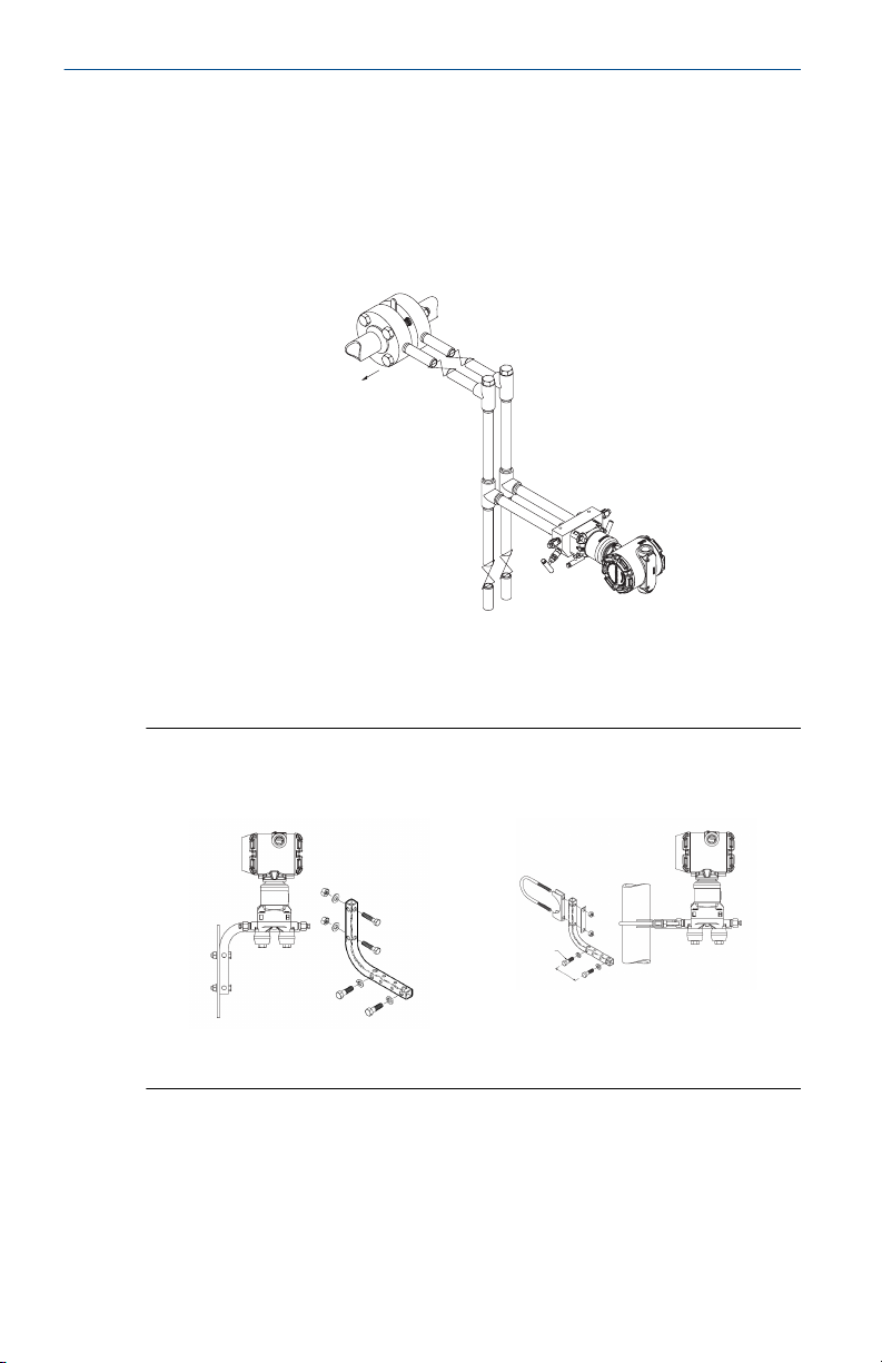
2.3 Steam flow applications
Procedure
1. Place taps to the side of the line.
2. Mount beside or below the taps.
3. Fill impulse lines with water.
A. Direction of flow
2.4 Mounting brackets
Figure 2-1: Mounting Bracket – Coplanar Flange
Panel mount
6 Rosemount 3051SMV
Pipe mount
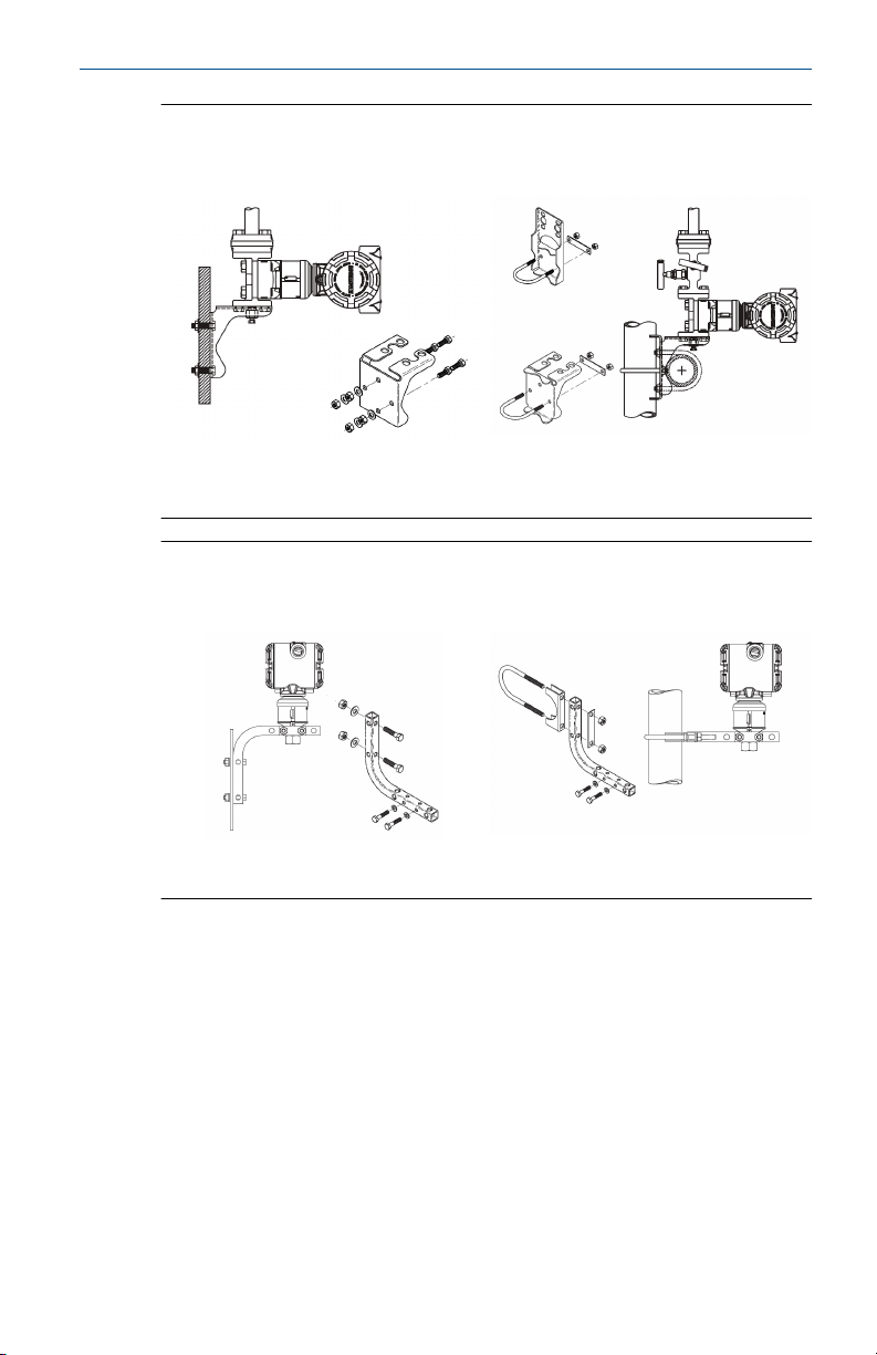
October 2021 Quick Start Guide
Figure 2-2: Mounting Brackets – Traditional Flange
Panel mount Pipe mount
Figure 2-3: Mounting Brackets – In-line
Panel mount Pipe mount
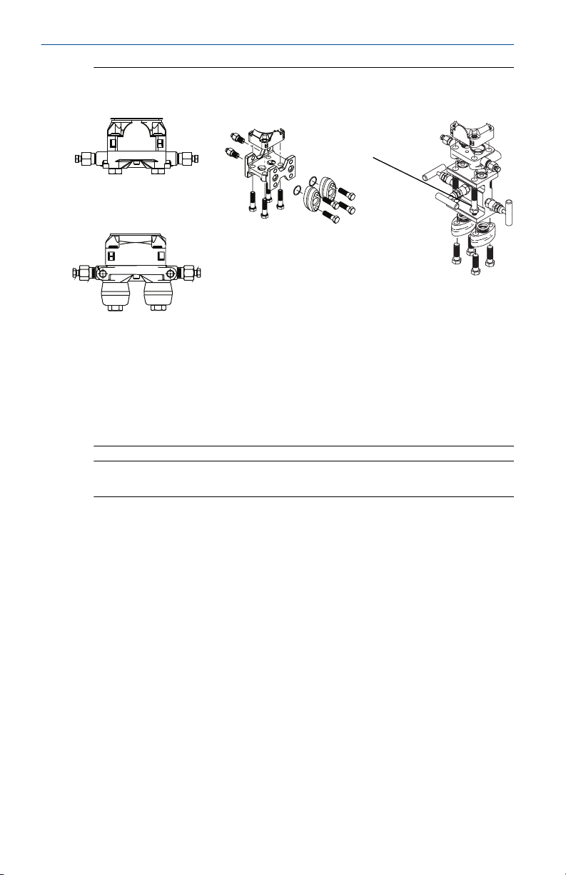
2.5 Bolting considerations
If the transmitter installation requires assembly of a process flange,
manifold, or flange adapters, follow these assembly guidelines to ensure a
tight seal for optimal performance characteristics of the transmitter. Only
use bolts supplied with the transmitter or sold by Emerson as spare parts.
Figure 2-4 illustrates common transmitter assemblies with the bolt length
required for proper transmitter assembly.
Quick Start Guide 7
A
4 × 1.75-in.
(44 mm)
D
4 × 1.75-in.
(44 mm)
4 × 2.25-in.
(57 mm)
C
4 × 1.75-in.
(44 mm)
4
× 1.50-in.
(38 mm)
B
4 × 2.88-in.
(73 mm)
Quick Start Guide October 2021
Figure 2-4: Common Transmitter Assemblies
A. Transmitter with coplanar flange
B. Transmitter with coplanar flange and optional flange adapters
C. Transmitter with traditional flange and optional flange adapters
D. Transmitter with coplanar flange and optional Rosemount Conventional
Manifold and flange adapters
Note
For all other manifolds, contact Customer Central technical support.
Bolts are typically carbon steel or stainless steel. Confirm the material by
viewing the markings on the head of the bolt and referencing Table 2-1 . If
bolt material is not shown in Table 2-1, contact the local Emerson
representative for more information.
Use the following bolt installation procedure:
Procedure
1. Carbon steel bolts do not require lubrication and the stainless steel
bolts are coated with a lubricant to ease installation. However, no
additional lubricant should be applied when installing either type of
bolt.
2. Finger-tighten the bolts.
3. Torque the bolts to the initial torque value using a crossing pattern.
See Table 2-1 for initial torque value.
4. Torque the bolts to the final torque value using the same crossing
pattern. See Table 2-1 for final torque value.
8 Rosemount 3051SMV

B7M
316
316
316
SW
316
STM
316
R
B8M
A
B
October 2021 Quick Start Guide
5. Verify the flange bolts are protruding through the sensor module
before applying pressure (see Figure 2-5).
Example
Table 2-1: Torque Values for the Flange and Flange Adapter Bolts
Bolt material Head markings Initial torque Final torque
Carbon Steel
300 in-lb 650 in-lb
(CS)
Stainless Steel
150 in-lb 300 in-lb
(SST)
Figure 2-5: Proper Bolt Installation
A. Bolt
B. Sensor module
Quick Start Guide 9

A
B
C
D
Quick Start Guide October 2021
2.6 O-rings with flange adapters
WARNING
Failure to install proper flange adapter O-rings may cause process leaks,
which can result in death or serious injury. Only use the O-ring that is
designed for its specific flange adapter.
A. Flange adapter
B. O-ring
C. PTFE-based profile (square)
D. Elastomer profile (round)
Whenever the flange or adapters are removed, visually inspect the O-rings.
Replace them if there are any signs of damage, such as nicks or cuts. If the Orings are replaced, re-torque the flange bolts and alignment screws after
installation to compensate for seating of the O-rings.
10 Rosemount 3051SMV

October 2021 Quick Start Guide
3 Consider housing rotation
To improve field access to wiring or to better view the optional LCD display:
Procedure
1. Loosen the housing rotation set screw.
2. Turn the housing up to 180° left or right of its original (as shipped)
position.
3. Re-tighten the housing rotation set screw.
Figure 3-1: Transmitter Housing Set Screw
A. LCD display
B. Housing rotation set screw (3/32-in.)
CAUTION
Do not rotate the housing more than 180° without first performing a
disassembly procedure. Over-rotation may sever the electrical
connection between the sensor module and the electronics.
Quick Start Guide 11
A B
Quick Start Guide October 2021
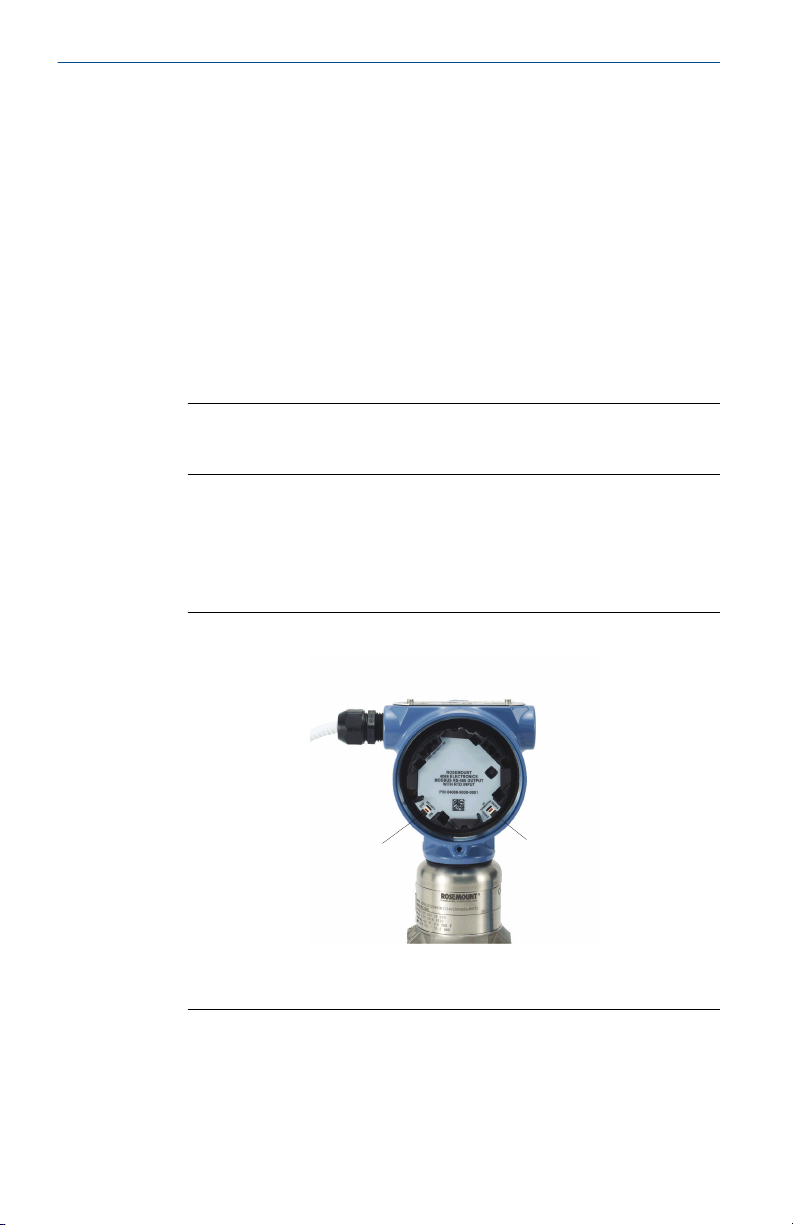
4 Set the switches
The transmitter’s default configuration sets the alarm condition to high (HI)
and the security to off.
Procedure
1. If the transmitter is installed, secure the bus and remove power.
2. Required: Remove the transmitter cover opposite the field terminal
side. Do not remove the instrument covers in explosive
environments when the circuit is live.
3. Slide the Security and Alarm switches into the preferred position by
using a small screwdriver.
Note
The Security switch will need to be in the off position in order to make
any configuration changes.
4. Required: In order to meet explosion-proof requirements, reinstall
the housing cover and tighten so the cover is fully seated with metal
to metal contact between the housing and cover. After the cover is
seated properly, replace the flathead screw located on the bottom of
the housing cover.
Figure 4-1: Transmitter Switch Configuration
A. Security
B. AC Termination
12 Rosemount 3051SMV

October 2021 Quick Start Guide
5 Connect wiring and power up
CAUTION
Do not connect the power across the test terminals. Power could damage
the test diode in the test connection. Twisted pairs yield best results. Use 24
to 14 AWG wire and do not exceed 5,000 ft. (1500 m).
Use the following steps to wire the transmitter:
Procedure
1. Remove the cover on the field terminals side of the housing.
2. Connect the positive lead to the “PWR/COMM +” terminal, and the
negative lead to the “PWR/COMM –” terminal.
3. If the optional process temperature input is not installed, plug and
seal the unused conduit connection. If the input is being utilized, see
Install optional process temperature input (Pt 100 RTD sensor) for
more information.
NOTICE
When the enclosed pipe plug is utilized in the conduit opening, it
must be installed with a minimum engagement of five threads to
comply with explosion-proof requirements. Refer to the Rosemount
3051SMV Reference Manual for more information.
™
4. If applicable, install wiring with a drip loop. Arrange the drip loop
so the bottom is lower than the conduit connections and the
transmitter housing.
5. Reinstall the housing cover and tighten so that metal contacts metal
to meet explosion-proof requirements.
Figure 5-1 shows the wiring connections necessary to power a
Rosemount 3051SMV and enable communications with a hand-held
Field Communicator.
Quick Start Guide 13

A
RL ≥ 250Ω
A
RL ≥ 250Ω
Quick Start Guide October 2021
Figure 5-1: Transmitter Wiring
Without optional process temperature
connection
With optional process temperature
connection
A. Power supply
Note
Installation of the transient protection terminal block does not
provide transient protection unless the Rosemount 3051SMV
housing is properly grounded.
5.1 Conduit electrical connector wiring (option GE or GM)
For Rosemount 3051SMV with conduit electrical connectors GE or GM, refer
to the cordset manufacturer’s installation instructions for wiring details. For
FM Intrinsically Safe, Division 2 hazardous locations, install in accordance
with Rosemount drawing 03151-1009 to maintain outdoor rating (NEMA
4X and IP66). See the Rosemount 3051SMV Reference Manual.
5.2
Power supply
The dc power supply should provide power with less than two percent ripple.
The total resistance load is the sum of the resistance of the signal leads and
the load resistance of the controller, indicator, intrinsic safety barriers, and
related components.
®
14 Rosemount 3051SMV

1322
1000
500
0
12.0 20 30
42.4
Voltage (Vdc)
Load (Ohms)
Operating
region
October 2021 Quick Start Guide
Figure 5-2: Load Limitation
Maximum loop resistance = 43.5 x (power supply voltage – 12.0)
HART communication requires a minimum loop resistance of 250Ω
5.3 Install optional process temperature input (Pt 100 RTD sensor)
Note
To meet ATEX/IECEx Flameproof certification, only ATEX/IECEx Flameproof
cables (temperature input code C30, C32, C33, or C34) may be used.
Procedure
1. Mount the Pt 100 RTD sensor in the appropriate location.
Note
Use shielded four-wire cable for the process temperature
connection.
2. Connect the RTD cable to the Rosemount 3051SMV by inserting the
cable wires through the unused housing conduit and connect to the
four screws on the transmitter terminal block. An appropriate cable
gland should be used to seal the conduit opening around the cable.
3. Connect the RTD cable shield wire to the ground lug in the housing.
Quick Start Guide 15

A
C
B
Red
Red
White
White
Quick Start Guide October 2021
Figure 5-3: RTD Wiring Connection
A. Ground lug
B. RTD cable assembly wires
C. Pt 100 RTD sensor
16 Rosemount 3051SMV

October 2021 Quick Start Guide
6 Engineering Assistant installation
Engineering Assistant 6.1 or later
The Rosemount 3051SMV Engineering Assistant 6.1 or later is PC-based
software that performs configuration, maintenance, diagnostic functions,
and serves as the primary communication interface to the transmitter with
the fully compensated mass and energy flow feature board.
The Rosemount 3051SMV Engineering Assistant software is required to
complete the flow configuration.
NOTICE
To ensure correct operation, download the most current version of the
Engineering Assistant software at Emerson.com/Rosemount-Engineering-
Assistant.
6.1 System requirements
The following are the minimum system requirements to install the
Rosemount 3051SMV Engineering Assistant software:
• Pentium®-grade processor: 500 MHz or faster
• Operating system: Windows™ XP Professional (32-bit), or Windows 7
(32-bit or 64-bit)
• 256 MB RAM
• 100 MB free hard disk space
• RS232 serial port or USB port (for use with HART® modem)
• CD-ROM
6.2
Install Rosemount 3051SMV Engineering Assistant 6.1 or later
Procedure
1. Uninstall any existing versions of Engineering Assistant 6.
2. Insert the new Engineering Assistant disk into the CD-ROM.
3. Windows should detect the presence of a CD and start the
installation program. Follow the on-screen prompts to finish the
installation. If Windows does not detect the CD, use Windows
Explorer or My Computer to view the contents of the CD-ROM, and
then double click the SETUP.EXE program.
Quick Start Guide 17
Loading...