

Quick Start Guide: Rosemount 3051HT Hygienic Pressure Transmitter with PROFIBUS PA Protocol
Table of contents
 Loading...
Rosemount Quick Start Guide: Rosemount 3051HT Hygienic Pressure Transmitter with PROFIBUS PA Protocol Manuals & Guides

Quick Start Guide
00825-0300-4091, Rev BA
June 2020
Rosemount™ 3051HT Hygienic Pressure
Transmitter
with PROFIBUS® PA Protocol

Quick Start Guide June 2020
Safety messages
NOTICE
This guide provides basic guidelines for the Rosemount 3051HT Transmitter. It does not provide
instructions for configuration, diagnostics, maintenance, service, troubleshooting, Explosion-proof,
Flameproof, or intrinsically safe (I.S.) installations.
WARNING
Explosions could result in death or serious injury.
Installation of device in an explosive environment must be in accordance with appropriate local,
national, and international standards, codes, and practices.
In an explosion-proof/flameproof installation, do not remove the transmitter covers when power is
applied to the unit.
Ensure device is installed in accordance with intrinsically safe or non-incendive field practices.
Before connecting a handheld communicator in an explosive atmosphere, ensure the instruments are
installed in accordance with intrinsically safe or non-incendive field wiring practices.
Verify that the operating environment of the gauge is consistent with the appropriate hazardous
locations certifications.
Electrical shock can result in death or serious injury.
Care must be taken during transportation of power module to prevent electrostatic charge build-up.
Device must be installed to ensure a minimum antenna separation distance of 8 in. (20 cm) from all
persons.
Process leaks may cause harm or result in death.
Handle the device carefully.
Physical access
Unauthorized personnel may potentially cause significant damage to and/or misconfiguration of end
users’ equipment. This could be intentional or unintentional and needs to be protected against.
Physical security is an important part of any security program and fundamental to protecting your
system. Restrict physical access by unauthorized personnel to protect end users’ assets. This is true for
all systems used within the facility.
Failure to follow safe installation guidelines could result in death or serious injury.
Ensure only qualified personnel perform the installation.
Apply wrench only to the flats, not on housing.
The battery is not replaceable in a hazardous location.
2 Emerson.com/Rosemount

June 2020 Quick Start Guide
CAUTION
Keep the vent path free of any obstruction, including but not limited to paint, dust, and lubrication by
mounting the device so the process can drain away.
Interfering or blocking the atmospheric reference port will cause the device to output erroneous
pressure values.
Keep the vent path free of any obstruction, including but not limited to paint, dust, and lubrication by
mounting the device so the process can drain away.
Absolute pressure devices are calibrated at the factory. Trimming adjusts the position of the factory
characterization curve. It is possible to degrade performance of the device if any trim is done
improperly or with inaccurate equipment.
Individuals who handle products exposed to a hazardous substance can avoid injury if they are
informed of and understand the hazard. The product being returned will require a copy of the required
Material Safety Data Sheet (MSDS) for each substance must be included with the returned goods.
Contents
Transmitter installation................................................................................................................ 5
Basic configuration.....................................................................................................................11
Product certifications................................................................................................................. 14
Quick Start Guide 3

Quick Start Guide June 2020
4 Emerson.com/Rosemount

June 2020 Quick Start Guide
1 Transmitter installation
1.1 Mount the transmitter
Place the transmitter to the desired orientation before mounting.
Transmitter must not be securely mounted or clamped in place when
changing transmitter orientation.
Conduit entry orientation
When installing a Rosemount 3051HT, it is recommended installing so a
conduit entry faces downward or parallel to the ground to maximize
drainability when cleaning.
Environmental seal for housing
Thread sealing (PTFE) tape or paste on male threads of conduit is required to
provide a watertight/dustproof conduit seal and meets requirements of
NEMA® Type 4X, IP66, IP68, and IP69K. Consult factory if other Ingress
Protection ratings are required.
Note
IP69K rating only available on units with a SST housing and option code V9 in
the model string.
For M20 threads, install conduit plugs to full thread engagement or until
mechanical resistance is met.
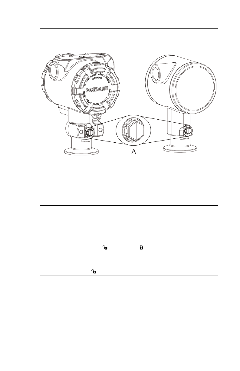
In-line gauge transmitter orientation
The low side pressure port (atmospheric reference) on the in-line gage
transmitter is located on the neck of the transmitter via a protected gage
vent (See Figure 1-1).
Keep the vent path free from obstructions including but not limited to paint,
dust, and viscous fluids by mounting the transmitter so the process can drain
away.
Quick Start Guide 5
Quick Start Guide June 2020
Figure 1-1: In-line Protected Gage Vent Low Side Pressure Port
Aluminum Polished 316 SST
A. Low side pressure port (atmospheric reference)
Clamping
When installing clamp, follow recommended torque values provided by
gasket manufacturer.
Note
To maintain performance, torquing a 1.5-in. Tri Clamp beyond 50 in-lb. is
not recommended on pressure ranges below 20 psi.
1.2
6 Emerson.com/Rosemount
Setting the security switch
The security switch allows ( ) or prevents ( ) any configuration of the
transmitter.
Note
Default security is off (
Setting the simulate switch
The security switch can be enabled or disabled in the software.
Procedure
1. If the transmitter is installed, secure the loop, and remove power.
2. Remove the housing cover opposite the field terminal side.
).
A
B
June 2020 Quick Start Guide
WARNING
Explosions could result in death or serious injury.
In an explosion-proof/flameproof installation, do not remove the
transmitter covers when power is applied to the unit.
3. Slide the security switch into the preferred position.
4. Reattach the transmitter housing cover.
Tighten the cover until there is no gap between the cover and
housing to comply with explosion proof requirements.
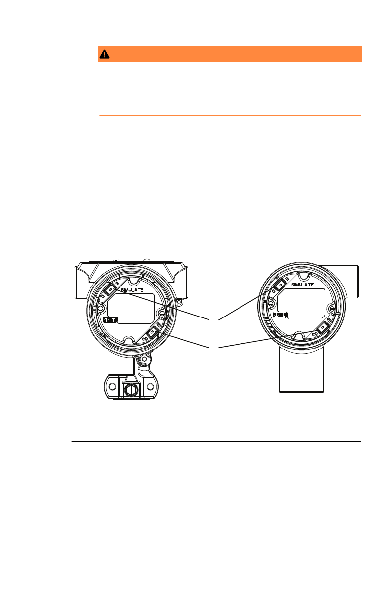
1.3 The security and simulate switches
The security and simulate switches are located on the electronics.
Figure 1-2: Transmitter Electronics Board
Aluminum Polished 316 SST
A. Simulate switch
B. Security switch
1.4
Quick Start Guide 7
Connect the wiring and power up
Procedure to connect the wiring and power up the transmitter.
Prerequisites
• Use copper wire of sufficient size to ensure the voltage across the
transmitter power terminals does not drop below 9 Vdc. A minimum of
12 Vdc under normal operating conditions is recommended. Shielded
twisted pair Type A cable is recommended.

Quick Start Guide June 2020
• Power supply voltage can be variable, especially under abnormal
conditions such as when operating on battery backup.
Procedure
1. To power the transmitter, connect the power leads to the terminals
indicated on the terminal block label.
Note
The Rosemount 3051 power terminals are polarity insensitive, which
means the electrical polarity of the power leads does not matter
when connecting to the power terminals. If polarity sensitive devices
are connected to the segment, terminal polarity should be followed.
When wiring to the screw terminals, the use of crimped legs is
recommended.
2. Ensure full contact with terminal block screw and washer. When
using a direct wiring method, wrap wire clockwise to ensure it is in
place when tightening the terminal block screw. No additional power
is needed.
Note
The use of a pin or a ferrule wire terminal is not recommended as the
connection may be more susceptible to loosening over time or under
vibration.
3. Ensure proper grounding. It is important the instrument cable shield
be:
a) Trimmed close and insulated from touching the transmitter
housing.
b) Connected to the next shield if cable is routed through a
junction box.
c) Connected to a good earth ground at the power supply end.
4. If transient protection is needed, refer to section Signal ground
wiring for grounding instructions.
5. Plug and seal unused conduit connections.
6. Reattach the transmitter covers.
a) The covers must only be capable of being released or
removed with the aid of a tool to comply with applicable
ordinary locations requirements.
Figure 1-3: Wiring
Aluminum
8 Emerson.com/Rosemount
Polished 316 SST
Loading...