

Quick Start Guide: Rosemount 3051HT Hygienic Pressure Transmitter with 4-20 mA HART Revision 5 and 7 Protocol
Table of contents
 Loading...
Rosemount Quick Start Guide: Rosemount 3051HT Hygienic Pressure Transmitter with 4-20 mA HART Revision 5 and 7 Protocol Manuals & Guides

Quick Start Guide
00825-0100-4091, Rev DA
June 2020
Rosemount™ 3051HT Hygienic Pressure
Transmitter
with 4–20 mA HART® Revision 5 and 7
Protocol

Quick Start Guide June 2020
NOTICE
This guide provides basic guidelines for the Rosemount 3051HT Transmitter. It does not provide
instructions for configuration, diagnostics, maintenance, service, troubleshooting, Explosion-proof,
Flameproof, or intrinsically safe (I.S.) installations.
WARNING
Explosions could result in death or serious injury.
Installation of device in an explosive environment must be in accordance with appropriate local,
national, and international standards, codes, and practices.
In an explosion-proof/flameproof installation, do not remove the transmitter covers when power is
applied to the unit.
Ensure device is installed in accordance with intrinsically safe or non-incendive field practices.
Before connecting a handheld communicator in an explosive atmosphere, ensure the instruments are
installed in accordance with intrinsically safe or non-incendive field wiring practices.
Verify that the operating environment of the gauge is consistent with the appropriate hazardous
locations certifications.
Electrical shock can result in death or serious injury.
Care must be taken during transportation of power module to prevent electrostatic charge build-up.
Device must be installed to ensure a minimum antenna separation distance of 8 in. (20 cm) from all
persons.
Physical access
Unauthorized personnel may potentially cause significant damage to and/or misconfiguration of end
users’ equipment. This could be intentional or unintentional and needs to be protected against.
Physical security is an important part of any security program and fundamental to protecting your
system. Restrict physical access by unauthorized personnel to protect end users’ assets. This is true for
all systems used within the facility.
Process leaks may cause harm or result in death.
Handle the device carefully.
Failure to follow safe installation guidelines could result in death or serious injury.
Ensure only qualified personnel perform the installation.
Apply wrench only to the flats, not on housing.
The battery is not replaceable in a hazardous location.
Contents
System readiness......................................................................................................................... 3
Transmitter installation................................................................................................................ 4
Product certifications................................................................................................................. 18
2 Emerson.com/Rosemount

June 2020 Quick Start Guide
1 System readiness
1.1 Confirm HART® Revision capability
• If using HART based control or asset management systems, confirm the
HART capability of those systems prior to transmitter installation. Not all
systems are capable of communicating with HART Revision 7 protocol.
This transmitter can be configured for either HART Revision 5 or 7
protocol.
• For instructions on how to change the HART Revision of your transmitter,
see Switch HART Revision mode.
1.2 Confirm correct device driver
• Verify the latest device driver (DD/DTM™) is loaded on your systems to
ensure proper communications.
• Download the latest device driver at Emerson.com or
FieldCommGroup.org.
Rosemount 3051 device revisions and drivers
Table 1-1 provides the information necessary to ensure you have the correct
device driver and documentation for your device.
Table 1-1: Rosemount 3051 Device Revisions and Files
Identify
Software
release date
Dec-11 01 7 10 See
(1) Device driver file names use device and DD revision, e.g. 10_01. HART Protocol is
designed to enable legacy device driver revisions to continue to communicate
with new HART devices. To access new functionality, the new device driver must
be downloaded. It is recommended to download new device driver files to
ensure full functionality.
(2) HART Revision 5 and 7 Selectable, Power Diagnostics, Safety Certified, Local
Operator Interface, Process Alerts, Scaled Variable, Configurable Alarms,
Expanded Engineering Units.
Quick Start Guide 3
device
HART
software
revision
Find device driver Review
HART
universal
revision
5 9
Device
revision
(1)
functionality
Changes to
software
(2)
of changes.
(2)
for list

Quick Start Guide June 2020
2 Transmitter installation
2.1 Mount the transmitter
Place the transmitter to the desired orientation before mounting.
Transmitter must not be securely mounted or clamped in place when
changing transmitter orientation.
Conduit entry orientation
When installing a Rosemount 3051HT, it is recommended installing so a
conduit entry faces downward or parallel to the ground to maximize
drainability when cleaning.
Environmental seal for housing
Thread sealing (PTFE) tape or paste on male threads of conduit is required to
provide a watertight/dustproof conduit seal and meets requirements of
NEMA® Type 4X, IP66, IP68, and IP69K. Consult factory if other Ingress
Protection ratings are required.
Note
IP69K rating only available on units with a SST housing and option code V9 in
the model string.
For M20 threads, install conduit plugs to full thread engagement or until
mechanical resistance is met.
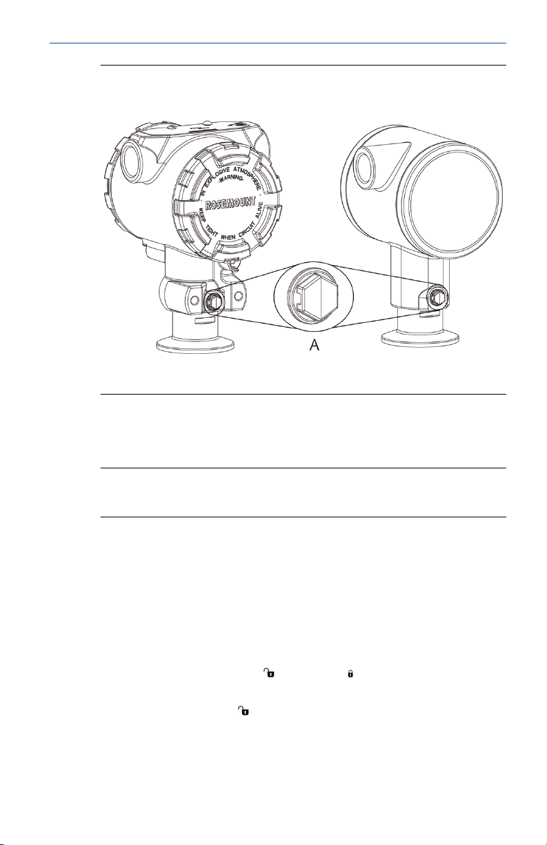
In-line gauge transmitter orientation
The low side pressure port (atmospheric reference) on the in-line gage
transmitter is located on the neck of the transmitter via a protected gage
vent (See Figure 2-1).
Keep the vent path free from obstructions including but not limited to paint,
dust, and viscous fluids by mounting the transmitter so the process can drain
away.
4 Emerson.com/Rosemount
June 2020 Quick Start Guide
Figure 2-1: In-line Protected Gage Vent Low Side Pressure Port
Aluminum Polished 316 SST
A. Low side pressure port (atmospheric reference)
Clamping
When installing clamp, follow recommended torque values provided by
gasket manufacturer.
Note
To maintain performance, torquing a 1.5-in. Tri Clamp beyond 50 in-lb. is
not recommended on pressure ranges below 20 psi.
2.2
Quick Start Guide 5
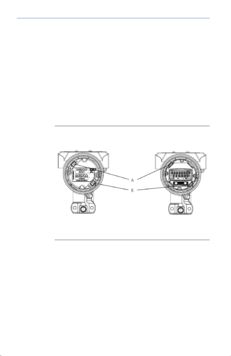
Set the switches
Prerequisites
Set alarm and security switch configuration before installation as shown in
Figure 2-2 and Figure 2-3.
• The alarm switch sets the analog output alarm to high or low.
• Default alarm is high.
• The security switch allows ( ) or prevents ( ) any configuration of the
transmitter.
• Default security is off (
Use the following procedure to change the switch configuration:
).
Quick Start Guide June 2020
Procedure
1. If the transmitter is installed, secure the loop, and remove power.
2. Remove the housing cover opposite the field terminal side. Do not
remove the instrument cover in explosive atmospheres when the
circuit is live.
3. Slide the security and alarm switches into the preferred position
using a small screwdriver.
4. Reattach the transmitter cover.
• The covers must only be capable of being released or removed
with the aid of a tool to comply with applicable ordinary locations
requirements.
• The cover must be fully engaged to comply with explosion-proof
requirements.
Figure 2-2: Transmitter Electronics Board - Aluminum
Without LCD display With LOI or LCD display
A. Alarm
B. Security
6 Emerson.com/Rosemount
DP
A
B
D
E
C
June 2020 Quick Start Guide
Figure 2-3: Transmitter Electronics Board - Polished 316 SST
Without LCD display With LOI or LCD display
A. Alarm
B. Security
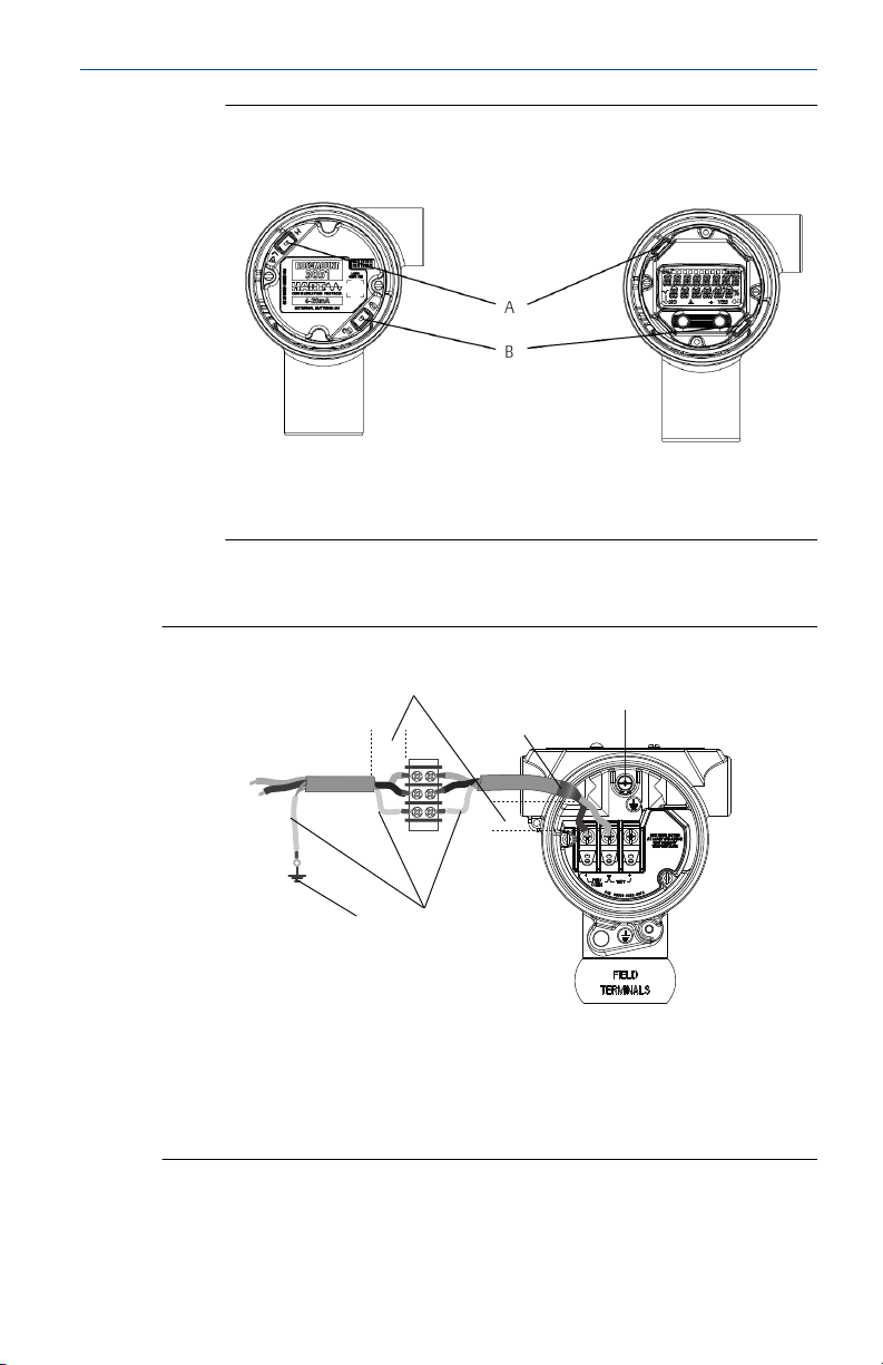
2.3 Connect the wiring and power up
Figure 2-4: Transmitter Wiring Diagrams (4–20 mA) - Aluminum
A. Minimize distance
B. Trim shield and insulate
C. Protective grounding terminal
D. Insulate shield
E. Connect shield back to the power supply ground
Quick Start Guide 7
DP
A
B
D
E
C
Quick Start Guide June 2020
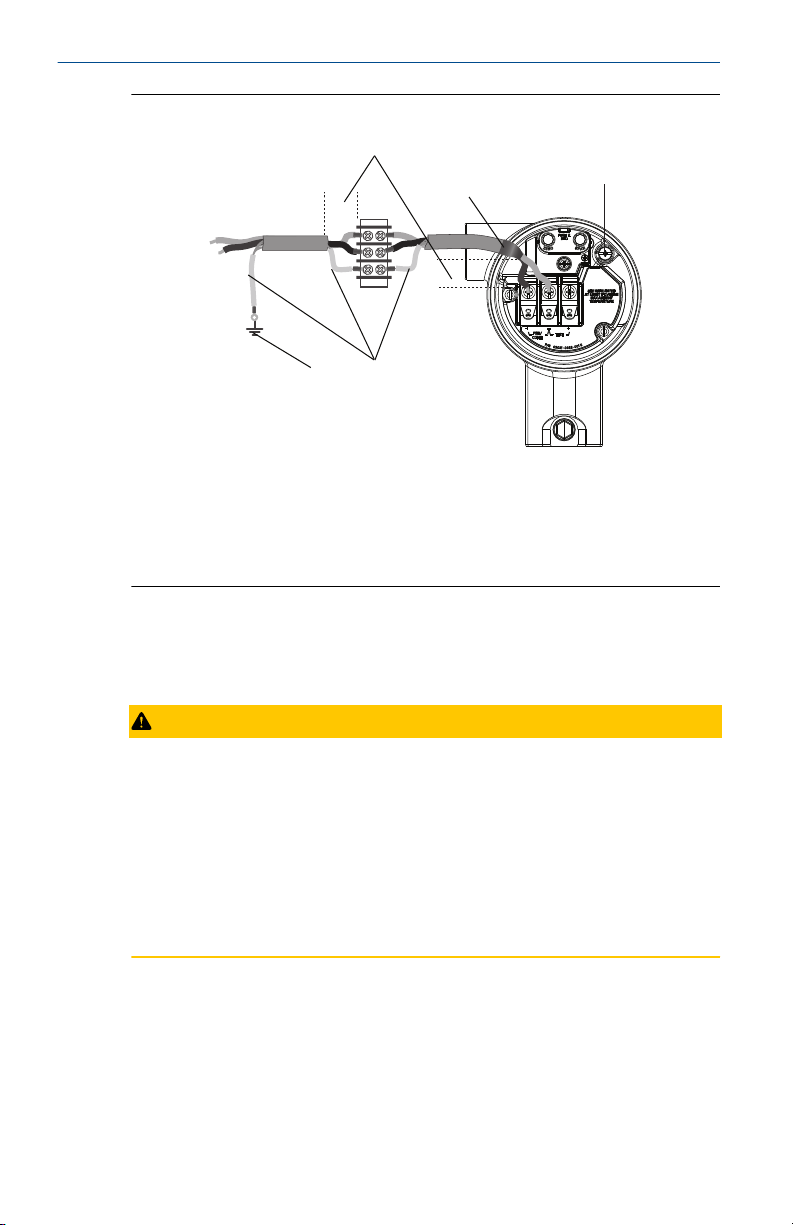
Figure 2-5: Transmitter Wiring Diagrams (4–20 mA) - Polished 316 SST
A. Minimize distance
B. Trim shield and insulate
C. Protective grounding terminal
D. Insulate shield
E. Connect shield back to the power supply ground
Shielded twisted pair cable should be used for best results. Use 24 AWG or
larger wire that does not exceed 5,000 ft. (1,500 m) in length. If applicable,
install wiring with a drip loop. Arrange the drip loop so the bottom is lower
than the conduit connections and the transmitter housing.
CAUTION
• Installation of the transient protection terminal block does not provide
transient protection unless the Rosemount 3051HT case is properly
grounded.
• Do not run signal wiring in conduit or open trays with power wiring, or
near heavy electrical equipment.
• Do not connect the powered signal wiring to the test terminals. Power
could damage the test diode in the terminal block.
Procedure
1. Remove the housing cover on the FIELD TERMINALS side.
2. Connect the positive lead to the “+” terminal (PWR/COMM) and the
negative lead to the “–” terminal.
8 Emerson.com/Rosemount

June 2020 Quick Start Guide
3. Ensure full contact with terminal block screw and washer. When
using a direct wiring method, wrap wire clockwise to ensure it is in
place when tightening the terminal block screw.
Note
The use of a pin or a ferrule wire terminal is not recommended as the
connection may be more susceptible to loosening over time or under
vibration.
4. Ground housing to fulfill local grounding regulations.
5. Ensure proper grounding. It is important the instrument cable shield
be:
• Trimmed close and insulated from touching the transmitter
housing
• Connected to the next shield if cable is routed through a junction
box
• Connected to a good earth ground at the power supply end
6. If transient protection is needed, refer to section Grounding for
transient terminal block for grounding instructions.
7. Plug and seal unused conduit connections.
8. Reattach the transmitter covers.
• The covers must only be capable of being released or removed
with the aid of a tool to comply with applicable ordinary locations
requirements.
• The cover must be fully engaged to comply with explosion-proof
requirements.
Quick Start Guide 9
Loading...