

00825-0100-4030, Rev GB
Rosemount™ 2120 Level Switch
Vibrating Fork
Quick Start Guide
March 2022

Quick Start Guide March 2022
Contents
About this guide...........................................................................................................................3
Installation................................................................................................................................... 5
Prepare the electrical connections..............................................................................................11
Connect wiring and power up.....................................................................................................26
Configuration.............................................................................................................................30
Operation...................................................................................................................................32
2 Rosemount 2120 Level Switch

March 2022 Quick Start Guide
1 About this guide
This Quick Start Guide provides basic guidelines for the Rosemount 2120.
Refer to the Rosemount 2120 Reference Manual for more instructions. The
manual and this guide are also available electronically at
Emerson.com/Rosemount.
1.1 Safety messages
WARNING
Failure to follow safe installation and servicing guidelines could result in
death or serious injury.
Ensure the level switch is installed by qualified personnel and in accordance
with applicable code of practice.
Use the level switch only as specified in this manual. Failure to do so may
impair the protection provided by the level switch.
The weight of a level switch with a heavy flange and extended fork length
may exceed 37 lb. (18 kg). A risk assessment is required before carrying,
lifting, and installing the level switch.
Repair, e.g. substitution of components, etc. may jeopardize safety and is
under no circumstances allowed.
WARNING
Explosions could result in death or serious injury.
Verify the operating atmosphere of the level switch is consistent with the
appropriate hazardous locations certifications.
Before connecting a handheld communicator in an explosive atmosphere,
ensure the instruments are installed in accordance with intrinsically safe or
non-incendive field wiring practices.
In explosion-proof/flameproof and non-incendive installations, do not
remove the housing cover when power is applied to the level switch.
The housing cover must be fully engaged to meet flameproof/explosionproof requirements.
Quick Start Guide 3

Quick Start Guide March 2022
WARNING
Electrical shock could cause death or serious injury.
Avoid contact with the leads and terminals. High voltage that may be
present on leads can cause electrical shock.
Ensure the power to the level switch is off, and the lines to any other external
power source are disconnected or not powered while wiring the level switch.
Ensure the wiring is suitable for the electrical current and the insulation is
suitable for the voltage, temperature, and environment.
WARNING
Process leaks could result in death or serious injury.
Ensure the level switch is handled carefully. If the process seal is damaged,
gas might escape from the vessel (tank) or pipe.
WARNING
Physical access
Unauthorized personnel may potentially cause significant damage to and/or
misconfiguration of end users’ equipment. This could be intentional or
unintentional and needs to be protected against.
Physical security is an important part of any security program and
fundamental to protecting your system. Restrict physical access by
unauthorized personnel to protect end users’ assets. This is true for all
systems used within the facility.
CAUTION
Hot surfaces
The flange and process seal may be hot at high process temperatures. Allow
to cool before servicing.
4 Rosemount 2120 Level Switch
A
B
A
B
OK
OK
A
B
C
OK OK
OK
March 2022 Quick Start Guide
2 Installation
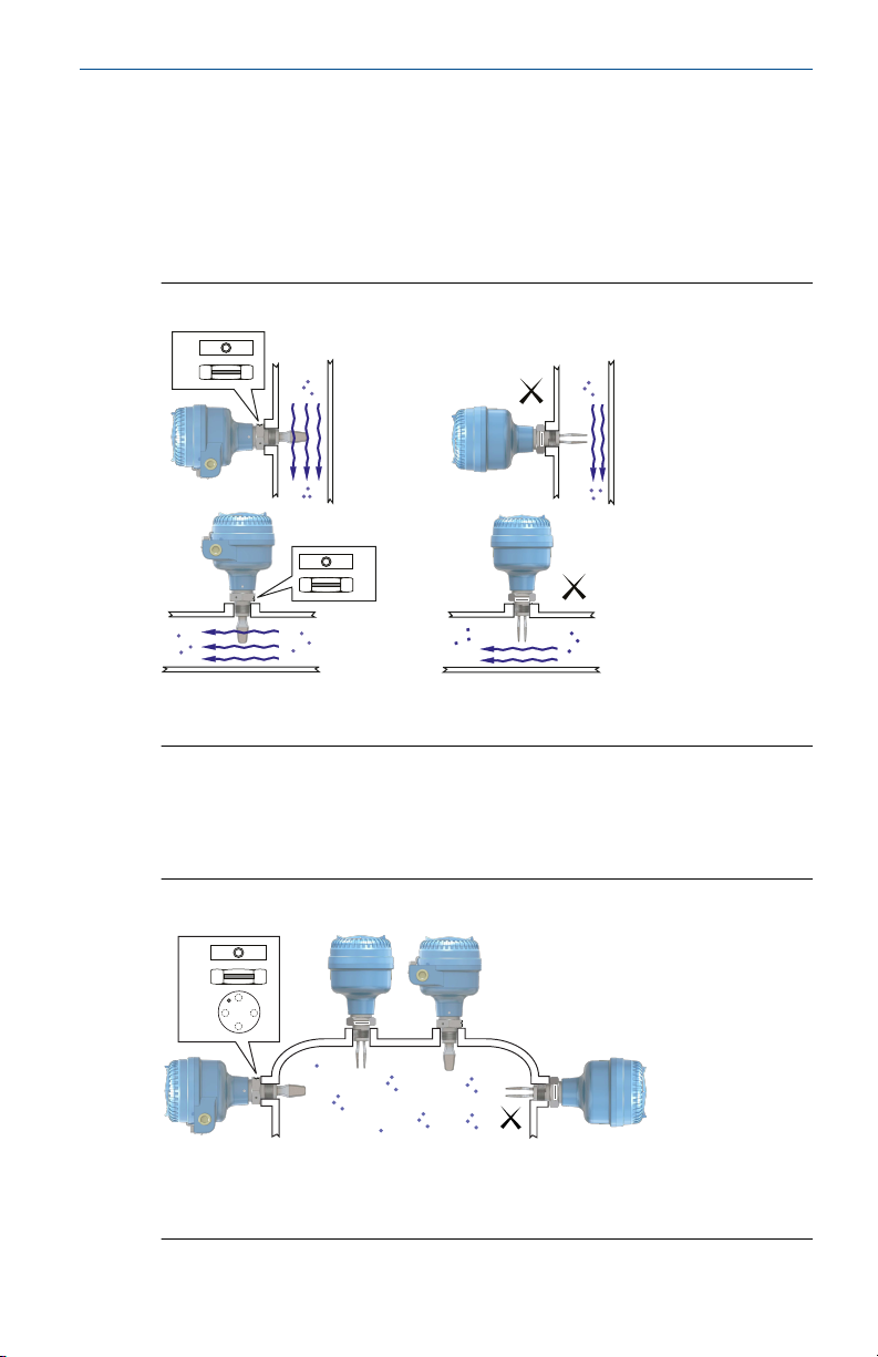
2.1 Fork alignment in a pipe installation
The fork is correctly aligned by positioning the groove or notch as indicated
(Figure 2-1).
Figure 2-1: Correct Fork Alignment for Pipe Installation
A. Tri Clamp process connections have a circular notch
B. Threaded process connections have a groove
2.2 Fork alignment in a vessel (tank) installation
The fork is correctly aligned by positioning the groove or notch as indicated
(Figure 2-2).
Figure 2-2: Correct Fork Alignment for Vessel (Tank) Installation
Quick Start Guide 5
A. Tri Clamp process connections have a circular notch
B.
Threaded process connections have a groove
Flanged process connections have a circular notch
C.
A
A
Quick Start Guide March 2022
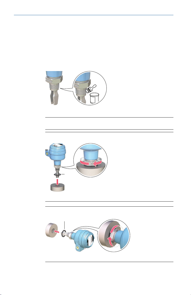
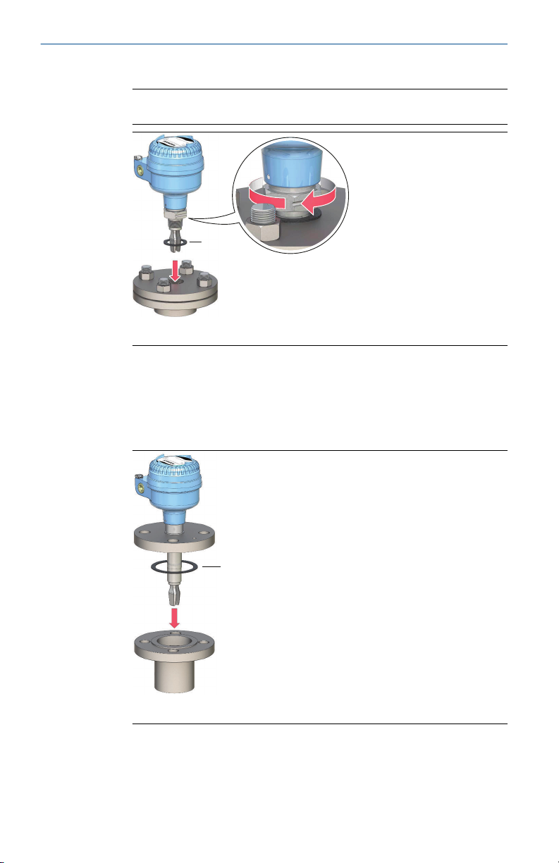
2.3 Mounting the threaded version
2.3.1 Threaded vessel (tank) or pipework connection
Procedure
1. Seal and protect the threads. Use anti-seize paste or PTFE tape
according to site procedures.
A gasket may be used as a sealant for BSPP (G) threaded connections.
2. Screw the level switch into the process connection.
Note
Tighten using the hexagon nut only.
Figure 2-3: Vertical Installation
A. Gasket for BSPP (G) threaded connection
Figure 2-4: Horizontal Installation
6 Rosemount 2120 Level Switch
A. Gasket for BSPP (G) threaded connection
A
March 2022 Quick Start Guide
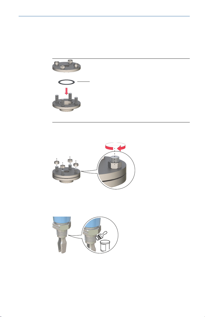
2.3.2 Threaded flange connection
Procedure
1. Place the customer-supplied flange and gasket on the vessel (tank)
nozzle.
A. Gasket (customer supplied)
2. Tighten the bolts and nuts with sufficient torque for the flange and
gasket.
3. Seal and protect the threads. Use anti-seize paste or PTFE tape
according to site procedures.
A gasket may be used as a sealant for BSPP (G) threaded connections.
Quick Start Guide 7
A
A
Quick Start Guide March 2022
4. Screw the level switch into the flange thread.
Note
Tighten using the hexagon nut only.
A. Gasket for BSPP (G) threaded connection
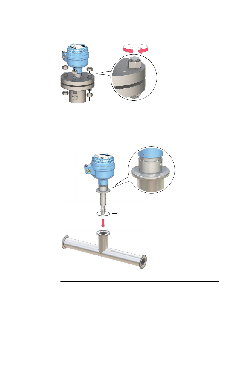
2.4 Mounting the flanged version
Procedure
1. Lower the level switch into the nozzle.
A. Gasket (customer supplied)
8 Rosemount 2120 Level Switch
A
March 2022 Quick Start Guide
2. Tighten the bolts and nuts with sufficient torque for the flange and
gasket.
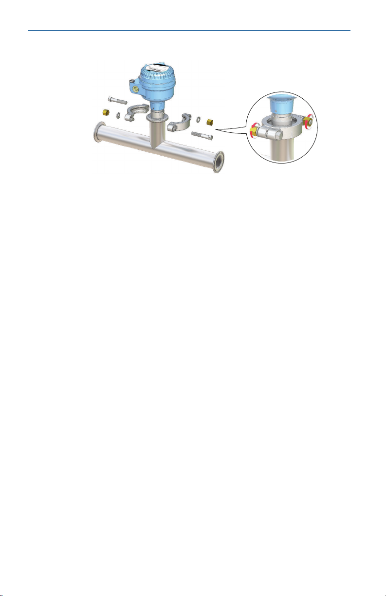
2.5 Mounting the Tri Clamp version
Procedure
1. Lower the level switch into the flange face.
A. Seal (supplied with Tri Clamp)
Quick Start Guide 9
Quick Start Guide March 2022
2. Fit the Tri Clamp.
10 Rosemount 2120 Level Switch

March 2022 Quick Start Guide
3 Prepare the electrical connections
3.1 Cable selection
Use 26–14 AWG (0.13 to 2.5 mm2) AWG wiring. Twisted-pairs and shielded
wiring is recommended for environments with high EMI (electromagnetic
interference). Two wires can be safely connected to each terminal screw.
3.2 Cable glands/conduits
For intrinsically safe, explosion-proof/flameproof, and dust-proof
installations, only use certified cable glands or conduit entry devices.
Ordinary location installations can use suitably rated cable glands or conduit
entry devices to maintain the Ingress Protection (IP) rating.
Unused conduit entries must always be sealed with a suitably rated
blanking/stopping plug.
Note
Do not run signal wiring in conduit or open trays with power wiring or near
heavy electrical equipment.
3.3 Power supply
The power supply requirements are dependent on the electronics selected.
• Direct load switching: 20 - 60 Vdc or 20 - 264 Vac (50/60 Hz)
• PNP/PLC electronics: 20 - 60 Vdc
• Relay DPCO (Double Pole Changeover) electronics (standard):
20 - 60 Vdc or 20 - 264 Vac (50/60 Hz)
• Relay DPCO electronics (12 Vdc nominal): 9 - 30 Vdc
• NAMUR electronics: 8 Vdc
• 8/16 mA electronics: 24 Vdc
3.4 Hazardous areas
When the device is installed in hazardous areas (classified locations), local
regulations and the conditions-of-use specified in applicable certificates
must be observed. Review the Rosemount 2120 Product Certifications
document for information.
Quick Start Guide 11
 Loading...