

Quick Start Guide: Rosemount™ 2051HT Hygienic Pressure Transmitter Profibus™
Table of contents
 Loading...
Rosemount Quick Start Guide: Rosemount™ 2051HT Hygienic Pressure Transmitter Profibus™ Manuals & Guides

Quick Start Guide
00825-0300-4591, Rev BA
November 2019
Rosemount™ 2051HT Hygienic Pressure
Transmitter
with PROFIBUS® Protocol

Quick Start Guide November 2019
Contents
About this guide...........................................................................................................................3
Transmitter installation................................................................................................................ 6
Basic configuration.....................................................................................................................13
Product certifications................................................................................................................. 16
2 Emerson.com/Rosemount

November 2019 Quick Start Guide
1 About this guide
1.1 Safety messages
This guide provides basic guidelines for the Rosemount 2051HT Transmitter.
It does not provide instructions for configuration, diagnostics, maintenance,
service, troubleshooting, Explosion-proof, Flameproof, or intrinsically safe
(I.S.) installations.
CAUTION
The products described in this document are NOT designed for nuclearqualified applications. Using non-nuclear qualified products in applications
that require nuclear-qualified hardware or products may cause inaccurate
readings. For information on Rosemount nuclear-qualified products, contact
your local Emerson Sales Representative.
Quick Start Guide 3

Quick Start Guide November 2019
WARNING
Explosions could result in death or serious injury.
Installation of this transmitter in an explosive environment must be in
accordance with the appropriate local, national, and international standards,
codes, and practices. Review the approvals section of this manual for any
restrictions associated with a safe
• Before connecting a Field Communicator in an explosive atmosphere,
ensure the instruments in the loop are installed in accordance with
intrinsically safe or non-incendive field wiring practices.
• In an explosion-proof/flameproof installation, do not remove the
transmitter covers when power is applied to the unit.
Process leaks may cause harm or result in death.
• Install and tighten process connectors before applying pressure.
• Do not attempt to loosen or remove flange bolts while the transmitter is
in service.
Electrical shock can result in death or serious injury.
• Avoid contact with the leads and terminals. High voltage that may be
present on leads can cause electrical shock.
• Before connecting a handheld communicator in an explosive
atmosphere, ensure the instruments in the loop are installed in
accordance with intrinsically safe or non-incendive field wiring practices.
• In an Explosion-Proof/Flameproof installation, do not remove the
transmitter covers when power is applied to the unit.
Process leaks may cause harm or result in death.
• Install and tighten process connectors before applying pressure.
Physical access
• Unauthorized personnel may potentially cause significant damage to
and/or misconfiguration of end users’ equipment. This could be
intentional or unintentional and needs to be protected against.
• Physical security is an important part of any security program and
fundamental to protecting your system. Restrict physical access by
unauthorized personnel to protect end users’ assets. This is true for all
systems used within the facility.
4 Emerson.com/Rosemount

November 2019 Quick Start Guide
WARNING
Replacement equipment or spare parts not approved by Emerson for use
as spare parts could reduce the pressure retaining capabilities of the
transmitter and may render the instrument dangerous.
• Use only bolts supplied or sold by Emerson as spare parts.
Improper assembly of manifolds to traditional flange can damage sensor
module.
For safe assembly of manifold to traditional flange, bolts must break back
plane of flange web (i.e., bolt hole) but must not contact sensor module
housing.
Physical access
• Unauthorized personnel may potentially cause significant damage to
and/or misconfiguration of end users’ equipment. This could be
intentional or unintentional and needs to be protected against.
• Physical security is an important part of any security program and
fundamental to protecting your system. Restrict physical access by
unauthorized personnel to protect end users’ assets. This is true for all
systems used within the facility.
Quick Start Guide 5

Start
Mount the
transmitter
Commissioning
tag
Done
Zero trim the
transmitter
Configuration
Grounding, wiring,
and power up
Set switches and
software write lock
Locate device
Quick Start Guide November 2019
2 Transmitter installation
Figure 2-1: Installation Flowchart
2.1 Mount the transmitter
Adjust the transmitter to desired orientation before mounting. Transmitter
must not be securely mounted or clamped in place when changing
transmitter orientation.
2.1.1 Conduit entry orientation
When installing a Rosemount 2051HT, it is recommended installing so a
conduit entry faces downward toward the ground to maximize drainability
when cleaning.
2.1.2 Environmental seal for housing
Thread sealing (PTFE) tape or paste on male threads of conduit is required to
provide a water/dust tight conduit seal and meets requirements of NEMA
Type 4X, IP66, IP68, and IP69K. Consult factory if other Ingress Protection
ratings are required.
For M20 threads, install conduit plugs to full thread engagement or until
mechanical resistance is met.
Note
IP69K rating only available on units with a SST housing and option code V9 in
the model string.
Note
For aluminum housings ordered with M20 conduit entries, transmitters
shipped will have NPT threads machined into the housing and a NPT to M20
6 Emerson.com/Rosemount
thread adapter will be provided. Considerations for environmental sealing
listed above should be taken into account when installing the thread
adapter.
®

A
November 2019 Quick Start Guide
2.1.3 In-line gage transmitter orientation
The low side pressure port (atmospheric reference) on the in-line gage
transmitter is located on the neck of the transmitter via a protected gage
vent (See Figure 2-2).
Keep the vent path free from obstructions including but not limited to paint,
dust, and viscous fluids by mounting the transmitter so the process can drain
away. Recommended installations have a conduit entry facing the ground so
the gage vent port is pointing parallel to the ground.
Figure 2-2: In-line Protected Gage Vent Low Side Pressure Port
Aluminum Polished 316 SST
A. Low side pressure port (atmospheric reference)
2.1.4 Clamping
When installing clamp, follow recommended torque values provided by
gasket manufacturer.
Note
To maintain performance, torquing a 1.5. Tri-Clamp® beyond 50 in-lb is not
recommended on pressure ranges below 20 psi.
2.2
Quick Start Guide 7
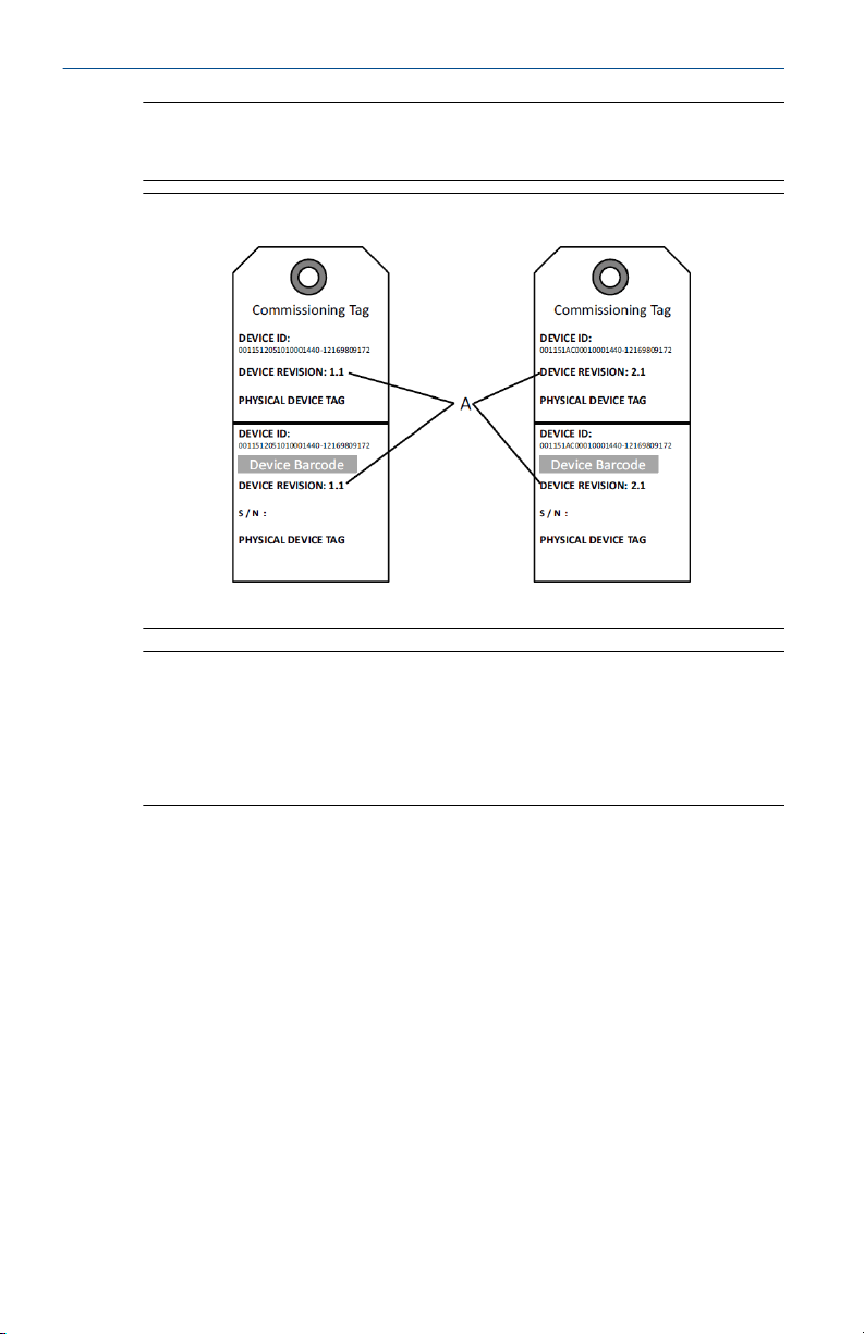
Commissioning (paper) tag
To identify which device is at a particular location use the removable tag
provided with the transmitter. Ensure the physical device tag (PD tag field) is
properly entered in both places on the removable commissioning tag and
tear off the bottom portion for each transmitter.
Quick Start Guide November 2019
Note
The device description loaded in the host system must be at the same
revision as this device.
Figure 2-3: Commissioning Tag
A. Device revision
Note
The device description loaded in the host system must be at the same
revision as this device. The device description can be downloaded from the
host system website or Emerson.com/Rosemount by selecting Download
Device Drivers under Product Quick Links. You can also visit Fieldbus.org and
select End User Resources.
2.3
8 Emerson.com/Rosemount
Setting security switch
Prerequisites
Set Simulate and Security switch configuration before installation as shown
in Figure 2-4.
• The simulate switch enables or disables simulated alerts and simulated
AI Block status and values. The default simulate switch position is
enabled.
• The Security switch allows (unlocked symbol) or prevents (locked
symbol) any configuration of the transmitter.
• Default security is off (unlocked symbol).
• The security switch can be enabled or disabled in software.
Use the following procedures to change the switch configuration:
Loading...