

Quick Installation Guide
Step 1: Mount the Transmitter
Step 2: Consider Housing Rotation
Step 3: Connect the Wiring and Power Up
Step 4: Configure the Transmitter
Step 5: Calibrate the Transmitter
Product Certifications
Start
End
Product Discontinued
00825-0100-4360, Rev BA
July 2009
Rosemount 1151
Rosemount 1151 Analog Pressure Transmitter
www.rosemount.com
¢00825-0100-4360N¤

Quick Installation Guide
IMPORTANT NOTICE
WARNING
00825-0100-4360, Rev BA
Rosemount 1151
© 2009 Rosemount Inc. All rights reserved. All marks property of owner. Rosemount and the Rosemount logotype are
registered trademarks of Rosemount Inc.
Emerson Process Management
Rosemount Division
8200 Market Boulevard
Chanhassen, MN USA 55317
T (US) (800) 999-9307
T (Intnl) (952) 906-8888
F (952) 949-7001
Emerson Process Management Asia
Pacific Private Limited
1 Pandan Crescent
Singapore 128461
T (65) 6777 8211
F (65) 6777 0947/65 6777 0743
This installation guide provides basic guidelines for Rosemount 1151 transmitters. It does
not provide instructions for configuration, diagnostics, maintenance, service,
troubleshooting, Explosion-Proof, Flame-Proof, or intrinsically safe (I.S.) installations.
Refer to the Rosemount 1151 reference manual (document number 00809-0100-4360)
for more instruction. This manual is also available electronically on
www.emersonprocess.com/rosemount.
Emerson Process Management GmbH & Co.
OHG
Argelsrieder Feld 3
82234 Wessling
Germany
T 49 (8153) 9390
F49 (8153) 939172
Beijing Rosemount Far East
Instrument Co., Limited
No. 6 North Street,
Hepingli, Dong Cheng District
Beijing 100013, China
T (86) (10) 6428 2233
F (86) (10) 6422 8586
July 2009
Explosions could result in death or serious injury:
Installation of this transmitter in an explosive environment must be in accordance with the
appropriate local, national, and international standards, codes, and practices. Please
review the approvals section of the 1151 reference manual for any restrictions associated
with a safe installation.
• In an Explosion-Proof/Flame-Proof installation, do not remove the transmitter covers
when power is applied to the unit.
Process leaks may cause harm or result in death.
• To avoid process leaks, only use the o-ring designed to seal with the corresponding
flange adapter.
Electrical shock can result in death or serious injury.
• Avoid contact with the leads and the terminals. High voltage that may be present on
leads can cause electrical shock.
2
Quick Installation Guide
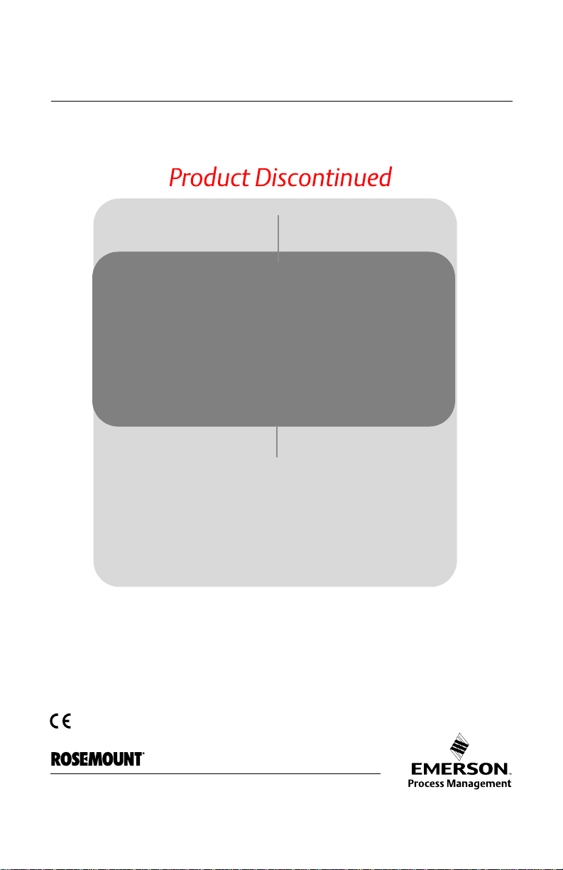
STEP 1: MOUNT THE TRANSMITTER
Flow
Flow
Flow
00825-0100-4360, Rev BA
July 2009
A. Applications
Liquid Flow Applications
1. Place taps to the side of the line.
2. Mount beside or below the taps.
Gas Flow Applications
1. Place taps in the top or side of the line.
2. Mount beside or above the taps.
Steam Flow Applications
1. Place taps to the side of the line.
2. Mount beside or below the taps.
3. Fill impulse lines with water.
Rosemount 1151
3
Quick Installation Guide
STEP 1 CONTINUED...
00825-0100-4360, Rev BA
Rosemount 1151
July 2009
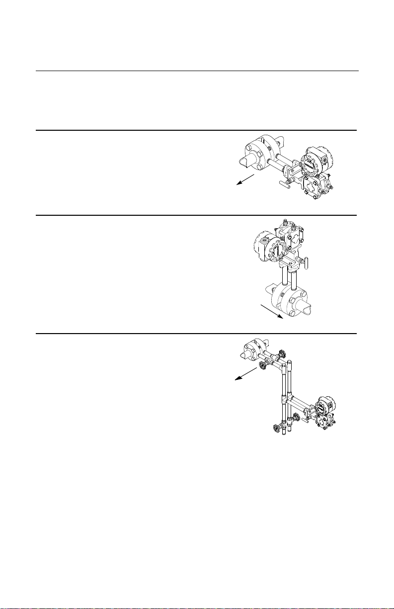
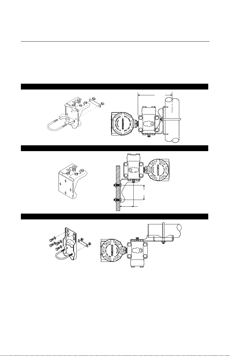
B. Optional Mounting Brackets
When installing the transmitter to one of the optional mounting brackets, torque the bracket
bolts to 125 in.-lbs. (0,9 N-m).
Pipe Mount
(1) Panel bolts are customer supplied.
Panel Mount
Flat Mount
(1)
4

Quick Installation Guide
STEP 1 CONTINUED...
WARNING
Rosemount 3051S / 3051 / 2051 / 3001 / 3095
Rosemount 1151
Flange Adapter
O-ring
Flange Adapter
O-ring
PTFE Based
Elastomer
PTFE
Elastomer
00825-0100-4360, Rev BA
July 2009
Rosemount 1151
C. O-rings with Flange Adapters
Failure to install proper flange adapter O-rings may cause process leaks, which can result in death or
serious injury. The two flange adapters are distinguished by unique O-ring grooves. Only use the O-ring
that is designed for its specific flange adapter, as shown below.
Whenever the flanges or adapters are removed, visually inspect the o-rings. Replace them if
there are any signs of damage, such as nicks or cuts. If you replace the o-rings, re-torque
the flange bolts and alignment screws after installation to compensate for seating of the
PTFE o-ring.
5
 Loading...