

00825-0100-4404, Rev AA
Perpetua® Power Puck® Solutions
Quick Start Guide
October 2015

Quick Start Guide
October 2015
This guide provides basic guidelines for the Power Puck. It does not provide
instructions for detailed configuration, diagnostics, maintenance, service,
troubleshooting, or installation of wireless devices. Refer to the wireless device
manuals and respective Quick Start Guides for more information.
Explosions could result in death or serious injury.
Installation of this Power Puck or intelligent power module (IPM) or both in an explosive environment must
be in accordance with the appropriate local, national, and international standards, codes, and practices.
Review the Product Certifications section for any restric tions associated with a safe installation.
Before connecting a Field Communicator in an explosive atmosphere, ensure the instruments are installed
in accordance with intrinsically safe or non-incendive field wiring practices.
Electrical shock can result in death or serious injury.
Avoid contact with the leads and terminals. High voltage that may be present on leads can cause electrical
shock.
Power Pucks and IPMs may be replaced in hazardous areas. The IPM has surface resistivity greater than one
gigaohm and must be properly installed in the wireless device enclosure.
Care must be taken during transportation to and from the point of installation to prevent electrostatic
charge build-up.
The Power Puck is designed for use on warm or hot surfaces and will generate heat itself; a burn hazard may
exist. Wear thermal gloves for protection during installation or when handling the Power Puck after
installation.
Each IPM contains two “C” size primary lithium batteries. Primary lithium batteries are regulated in
transportation by the U.S. Department of Transportation, and are also covered by IATA (International Air
Transport Association), ICAO (International Civil Aviation Organization), and ARD (European Ground
Transportation of Dangerous Goods). It is the responsibility of the shi pper to e nsure c omplian ce with these o r
any othe r local requ irements. Cons ult current r egulations a nd requirements before ship ping.
Contents
What’s in the box? . . . . . . . . . . . . . . . . . . . page 3
Attach to heat source . . . . . . . . . . . . . . . . page 4
Connect to transmitter . . . . . . . . . . . . . . . page 6
2
Verify voltage and base temperature . . . page 7
Troubleshooting . . . . . . . . . . . . . . . . . . . . page 8
Product Certifications . . . . . . . . . . . . . . . page 10
October 2015
Quick Start Guide
What’s in the box?
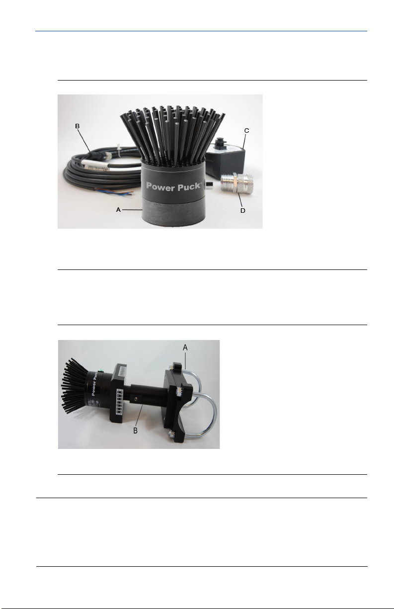
Power Pucks for magnetic mount applications include four basic components.
Figure 1. Magnetic Mount Components
A. Power Puck
B. Power cable
C. IPM (interface to the transmitter)
D. Cable gland
Power Pucks for pipe mount applications also include pipe adapters with sizes
ranging from 1- to 12-in. nominal pipe size (NPS), and temperature-reducing heat
extenders to accommodate higher pipe temperatures (see
Figure 2).
Figure 2. Pipe Mount Components
A. Pipe adapter (1- to 12-in. NPS pipe)
B. High temperature heat extender (3- or 6-in.)
Note
The following equipment may be needed for installation:
Protective thermal gloves
Wire stripper/cutter
3
/8- in. Allen wrench
Small, slotted screw driver
1
/2- and 9/16-in. wrench
Adjustable wrench
Wire br ush or emery cloth
PTFE tape
3
Quick Start Guide
Step 1: Attach to heat source
Power Pucks are mounted in two primary configurations:
Magnetic mount
Pipe mount
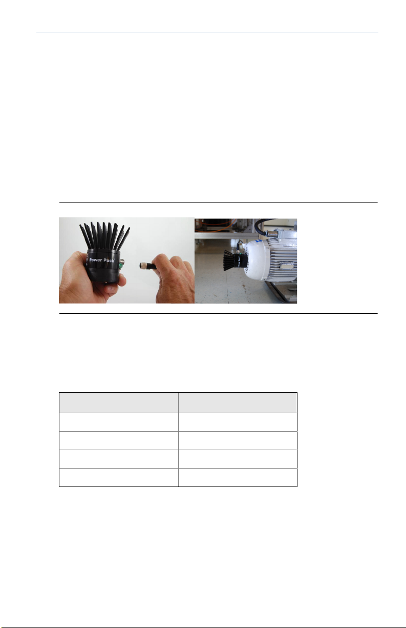
Magnetic mount Power Pucks
1. Attach the connector (4-pin M12) end of the cable to the Power Puck
Figure 3).
(see
2. Place the Power Puck on a flat metal surface that is less than 105 °C (220 °F)
(Figure 3). A surface that is smooth, clean, and vertical, with the Power Puck
mounted horizontally, provides the most efficient operation.
3. Proceed to
Figure 3. Connect Cable and Attach Power Puck to Flat Metal Surface
Connect to transmitter.
October 2015
Pipe mount Power Pucks
Pipe mount Power Pucks include four configurations, based on the maximum
variable temperature of the heat source (see Tab l e 1).
Table 1. Pipe Mount Configurations by Temperature Category
Heat source category
(maximum variable temperature)
-45 °C to 105 °C
(-50 °F to 220 °F)
106 °C to 175 °C
(221 °F to 350 °F)
176 °C to 290 °C
(351 °F to 550 °F)
-291 °C to 450 °C
(551 °F to 845 °F)
1. If the pipe is insulated, remove approximately six inches of insulation where
the Power Puck will be installed.
2. Using a wire brush, emery cloth, or compressed air, create a clean, smooth
area on the pipe where the Power Puck will be mounted.
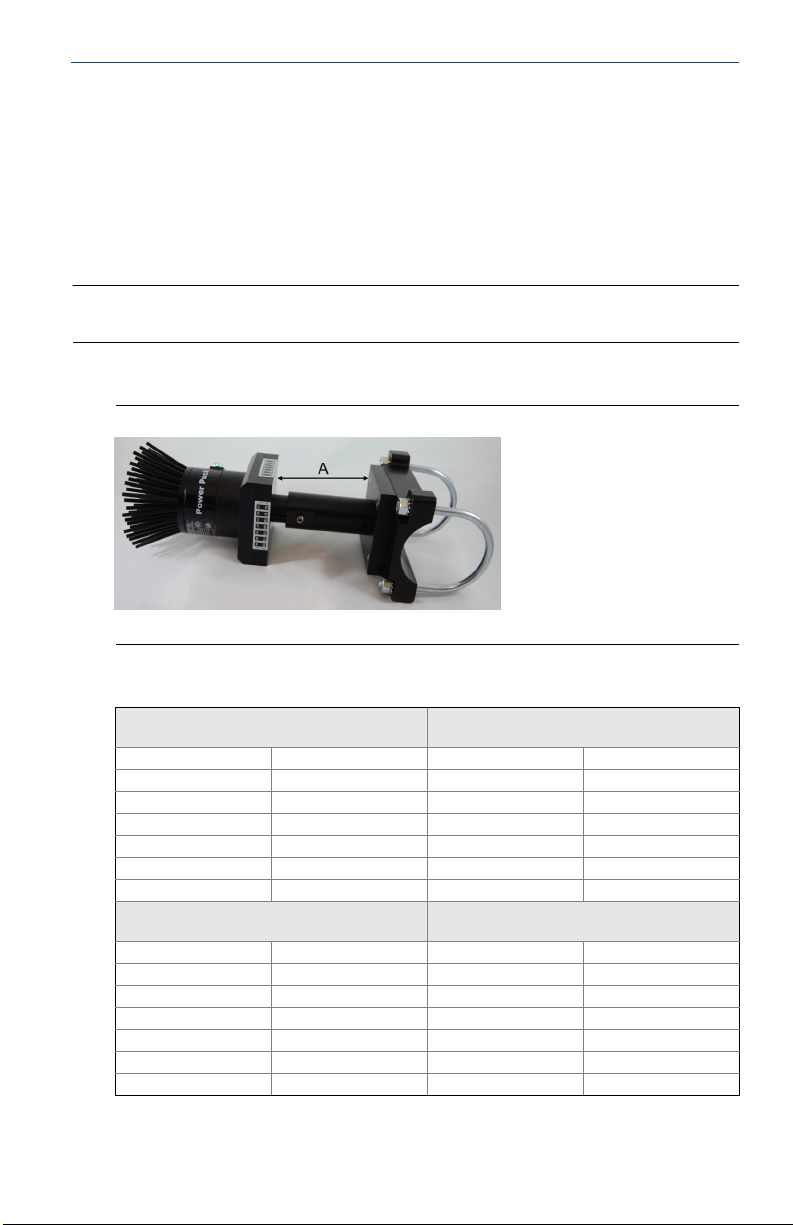
3. (if using 6-in. heat extender) With the included Allen wrench, loosen the set
screw in the heat extender and configure the extender using
Ta bl e 2.
4
Pipe mount configuration
Pipe mount with adapter only
(no heat extender)
Pipe mount with 3-in. heat extender
(no extension, insulated)
Pipe mount with 6-in. heat extender
(extended, insulated)
Pipe mount with 6-in. heat extender
(extended, no insulation)
Figure 4 and
October 2015
4. Remove the U-bolts and combination hex/lock nuts from the pipe adapter.
Place the Power Puck and adapter assembly on the pipe in a vertical position.
5. Reinstall the U-bolts and lightly tighten the hex/lock nuts.
6. Rotate the Power Puck and adapter assembly to a horizontal position and
tighten the hex/lock nuts to about 10 foot-pounds.
7. Connect the M12 connector end of the cable to the Power Puck.
8. Reinsulate the pipe, adapter base, and heat extender.
Note
With heat sources above 290 °C, do not insulate the heat extender.
9. Proceed to Connect to transmitter.
Figure 4. 6-in. Heat Extender Base-to-Base Measurement
A. Base-to-base measurement
Quick Start Guide
Table 2. 6-in. Heat Extender Lengths for Temperature Ranges
Heat source range
(maximum variable temperature)
Celsius Farenheit Centimeters Inches
190 or less 375 or less Fully collaps ed Fully collapsed
191-210 376-410 18.4 7.25
211-230 411-445 20.3 8.00
231-250 446-480 22.9 9.00
251-270 481-520 24.8 9.75
271-290 521-550 26.7 10.50
Heat source range
(maximum variable temperature)
Celsius Farenheit Centimeters Inches
291-320 551-610 20.3 8.00
321-350 611-660 21.6 8.50
351-380 661-715 22.9 9.00
381-410 716-770 24.1 9.50
411-440 771-825 25.4 10.00
441-450 826-845 26.0 10.25
Base-to-base extension (insulated)
Base-to-base extension
(not insulated)
5
 Loading...