


Enhanced 3051 Upgrade Kit
00825-0300-4007, Rev AB
June 2016
Enhanced Rosemount™ 3051 Upgrade
Kit
Spare Parts Installation Guide
Contents
Identify device . . . . . . . . . . . . . . . . . . . . . . . . . . . 2
Gather necessary external configuration button
assembly components . . . . . . . . . . . . . . . . . . . . 3
Remove existing retainer button assemblies . 4
Insert new retainer button assemblies . . . . . . . 4
Replace electronics board. . . . . . . . . . . . . . . . . . 7
Upload new device driver (DD/DTM) . . . . . . . . 8
External Buttons Installation Guide
A
B
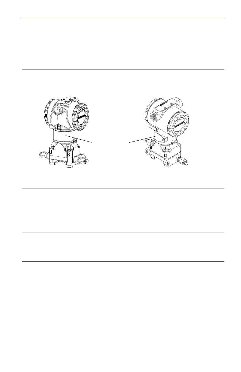
Step 1: Identify device
External button installation is dependant on what device is being upgraded in
addition to the housing material (Aluminum or Stainless Steel). The two types of
devices are the Enhanced Rosemount 3051 and Standard Rosemount 3051
pictured in Figure1.
Figure 1. Enhanced and Standard Rosemount 3051
Enhanced 3051 Standard 3051
A. Wrap around tag
B. Riveted tag
June 2016
By referencing Figure 1, there is a distinct difference between the Enhanced and
Standard 3051 in the neck label. The Enhanced Rosemount 3051 utilizes a
wraparound (rivet less) neck label, standard Rosemount 3051 uses a riveted label
that does not fully wrap around.
Note
For wrap around neck labels verify that option code “TR” is not specified on the transmitter model
string (engraved on the neck label). Option code “TR” indicates a 3051 Rev5 Transmitter that is not
compatible with the Enhanced 3051 Upgrade Kits.
2
June 2016
LABEL
-3001 / AB
COMMUNICATION PROTOCOL
P/N 03031-0020-3100
4-20mA
EXTERNAL BUTTONS: DZ
LABEL
-3101 / AB
P/N 03031-0020-3110
COMMUNICATION PROTOCOL
EXTERNAL BUTTONS: D4
P/N 03031-0020-3120
LABEL
-3201 / AB
COMMUNICATION PROTOCOL
4-20mA
EXTERNAL BUTTONS: M4
LABEL
-3301 / AB
P/N 03031-0020-3130
COMMUNICATION PROTOCOL
External Buttons Installation Guide
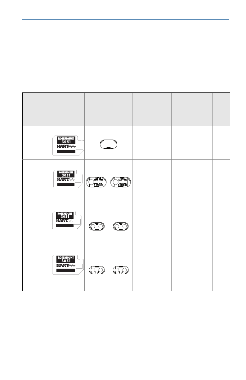
Step 2: Gather necessary external configuration button assembly components
After the device has successfully been identified, the correct retainer button
assembly components should be gathered. The retainer and buttons used in this
installation are dependant on the current housing they are being installed on
(Enhanced or Standard Rosemount 3051). Follow Table 1 below to gather the
correct configuration button assembly parts.
Table 1. Spare Parts Kits
Kit Number
03031-00203100
(no
configuration
Buttons)
03031-00203110
(Digital Zero
Tri m)
03031-00203120
(Analog Zero
and Span)
03031-00203139
(Local
Operator
Interface)
Electronics
Board
4-20mA
DZ
4-20mA
D4
M4
Retain er
(includes Rubber
Gasket)
Enhanced
3051
Standard
Blue
1
Blue
Grey Blue
Green Purple
3051
Blue
Standard 3051
(Buttons)
AL
Housing
Housing
SST
Enhanced 3051
(Buttons)
AL
Housing
Housing
N/A N/A N/A N/ A 0
1 – Blue 1 - Black 1 - Grey 1 - Black 1
2
2 - Blue 2 - Black 2 - Grey 2 - Green 2
2 - Blue 2 - Black 2 - Grey 2 - Green 2
Springs
SST
1. Retainer has thickness of 0.18 inches.
2. Retainer has a thickness of 0.12 inches.
3
 Loading...