

Rosemount Quick Start Guide: 6888A with Integral Autocalibration | Rosemount Manuals & Guides
Quick Start Guide
Rosemount
TM
6888 Analyzer
Overview
The 6888 is a combustion analyzer which measures the oxygen remaining in ue gases from any
combustion process (boiler, furnace, etc.) by controlling the air to fuel ratios, the optimum
ue gas O2 variations in air density, or fuel BTU that are compensated. Other benets are reaching
maximum efciency with the lowest NOx and minimum CO2 emissions.
This latest version of the 6888 has an optional online Calibration Recommended diagnostic to
indicate when the analyzer needs to be calibrated.
Also, internal gas-switching solenoids direct calibration gases to the sensing cell, which provides
on-line calibration, all while the boiler or furnace is in operation.
Calibrations can also be initiated based on time since last calibration or manually.
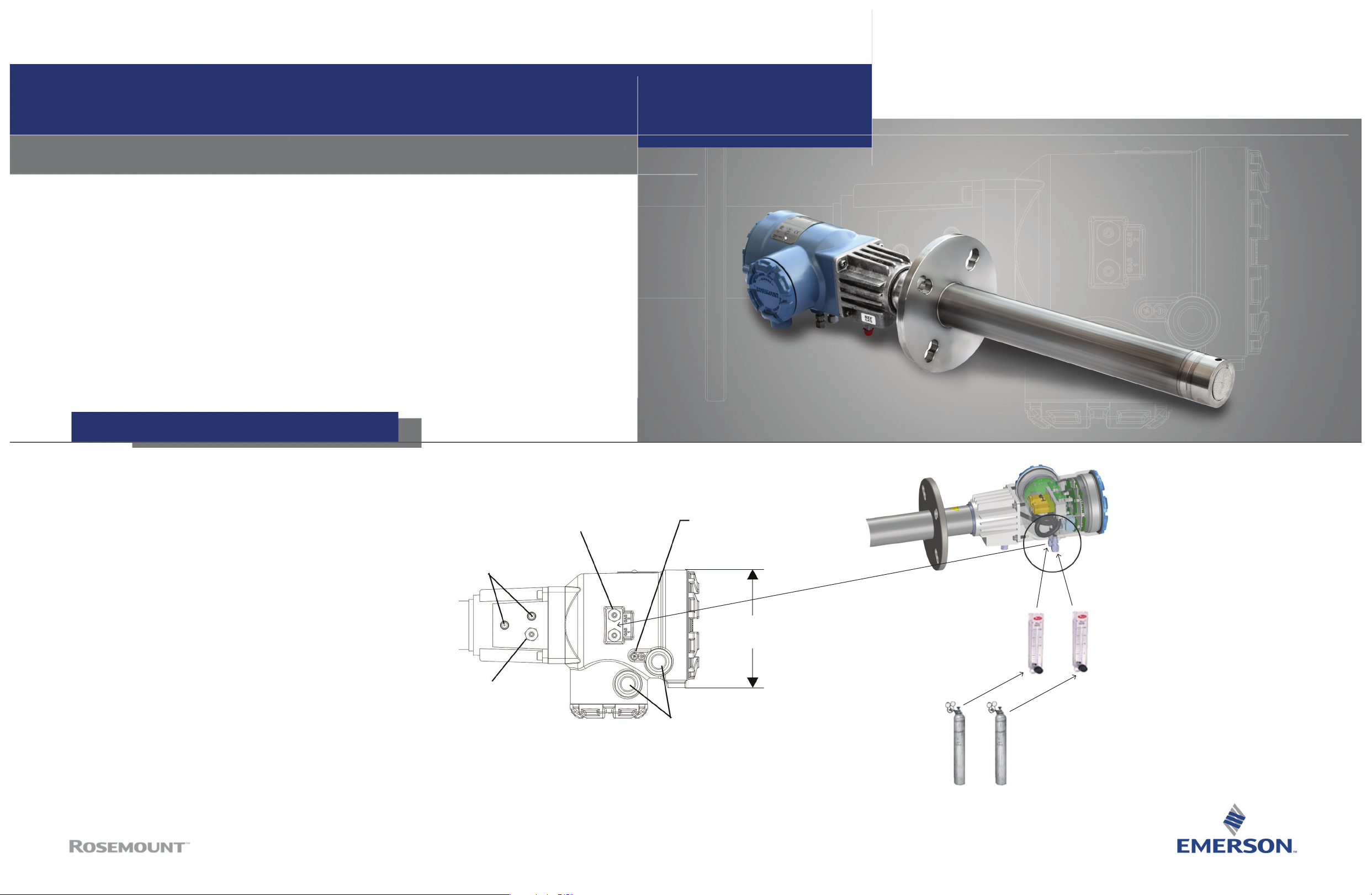
Pneumatic Installation
Manual bottle-switching is not possible with this
system, so do a good job on the installation. Do a leak
check on all the ttings to prevent bleeding of the cal gas
bottles over time.
Reference air is optional. (You can just leave this port
open to atmosphere.)
If used, make sure that the instrument air is clean and
dry, and mount the reference air owmeter similarly to
the cal gas owmeters.
CMB_QS_6888AutoCal
July 2017
Reference Air Vents
Reference Gas
1/4 Tube Fitting
2.0 SCFH (1.0 L/min)
20 PSI (138k Pa)
Calibration Gas
1/4 Tube Fittings
5.0 SCFH (2.4 L/min)
20 PSI (138 kPa)
#10 Soc Hd Cap Scr
(EXTERNAL GROUND)
[138.4]
1/2 NPT
Conduit Connection
(POWER, SIGNAL)
5.45
Pipe cal gases into bottom,
and out the top
Use dual-stage
pressure regulators
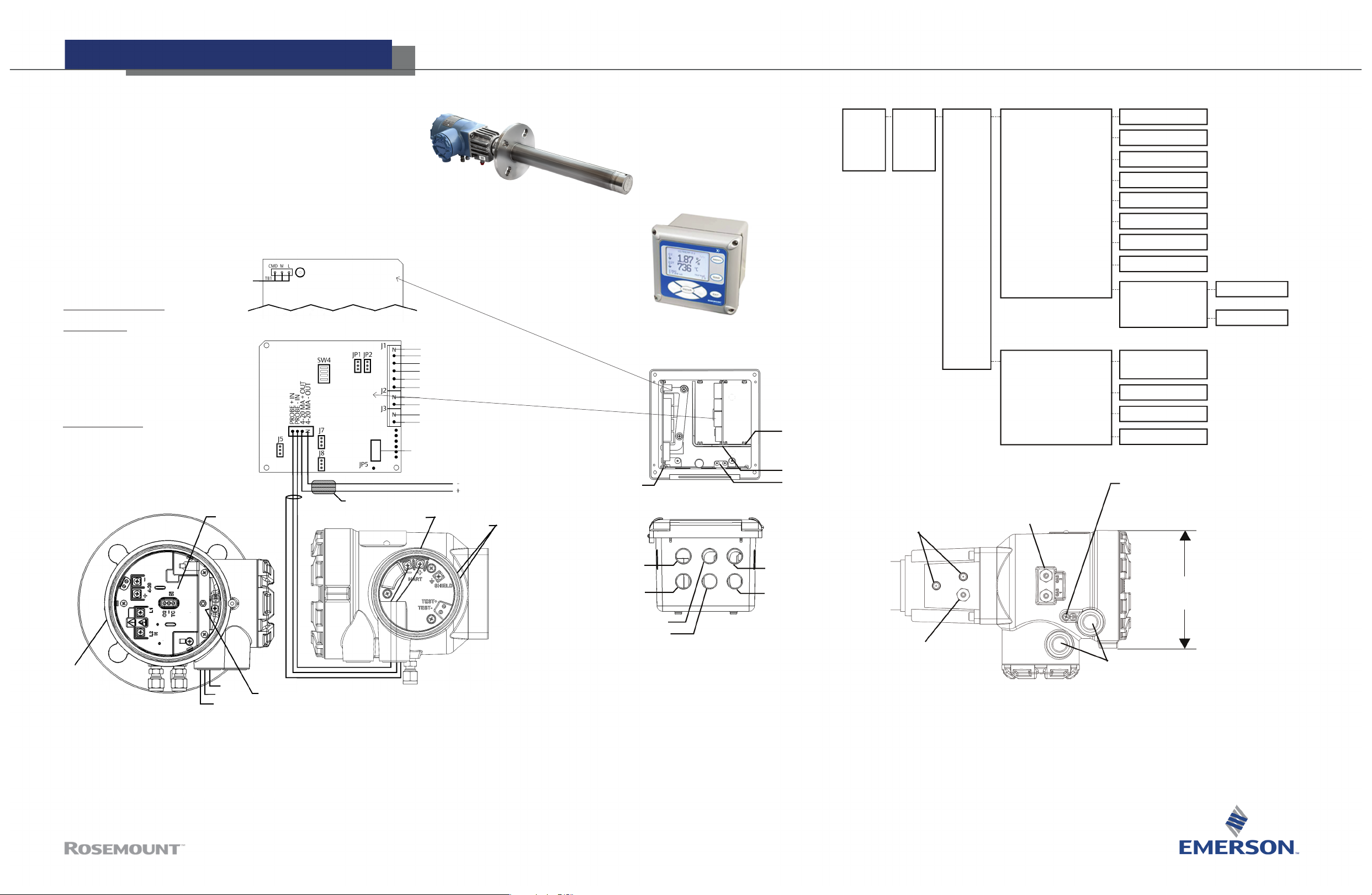
HART Electrical Installation
Notes:
Except for JP5, JP7, and JP8 on the IO Board, jumper and switch setting
are factory set and are shown for reference only.
IO Board 4–20 mA/HART loop power settings
JP5: Pins 1–2 Internal power 6888Xi to 6888 Transmitter
Pins 2–4 External power 6888Xi to 6888 Transmitter
(Requires 250 Resistor across J4, PR+ to PR-)
JP7/JP8: Pins 1–2 Internal power 6888Xi to DCS
Pins 2–4 External power 6888Xi to DCS
Power Supply Board
AC Input
IO Board Switch / Jumpers
Jumper Settings
JP1: Pins 2–3
JP2: Pins 2–3
JP5: Pins 1–2 Int power
Pins 2–3 Ext power
JP7: Pins 1–2 Int power
Pins 2–3 Ext power
JP8: Pins 1–2 Int power
Pins 2–3 Ext power
SW4 Switch Settings
Pos 1 - Off
Pos 2 - Off
Pos 3 - Off
Pos 4 - Off
Test Point Group
IO Board - Channel 1
PR+
PR-
Ferrite Clamp
Power Supply Card
Alarm 1 NO
Alarm 1 COM
Alarm 1 NO
Alarm 2 NO
Alarm 2 COM
Alarm 2 NO
FS
}
Optional
FS
CAL INIT
INPUT
Ribbon Cable to display
BOARD J2 “Sensor 1”
4–20 MA/HART
Signal
Test Points
With FOUNDATION™ eldbus probes
no Xi is required to conduct AutoCal
Note: I/O Board - Channel 2 is a
duplicate of Channel 1
OUTPUT
I/O Card
Power Supply
Board
6888 XI
Front View
6888 XI
Bottom View
Xi electronics
Channel #1
IO Board
Channel #2
IO Board
Shield Ground
Recommended Menu selections
PROBE #1
Detailed
Setup
Reference Air Vents
Calibration AO TRACK
Auto
Calibration
Enable Auto Cal
Start on Cal Recommended
Cal Interval
Next Cal Time
Calibration Gas
1/4 Tube Fittings
5.0 SCFH (2.4 L/min)
20 PSI (138 kPa)
TOL CHECK
CAL Recommended
CAL Acknowledge
CAL Gas #1
CAL Gas #2
Gas Time
Purge Time
Diffuser
Yes
No
Yes
No
0.4 % O
2
8 % O
2
300 Seconds
300 Seconds
Plugged Diffuser
Auto Advance CAL
No - Std. Housing
Yes - AutoCal Housing
No
672 hours (1 month)
Variable
#10 Soc Hd Cap Scr
(EXTERNAL GROUND)
Rate
Yes
- 9999 = manual initiate
Power
GND
L2
Transmitter Probe
Field Connections
©2017 Emerson Automation Solutions. All rights reserved.
L1
#8 Pan Hd Scr
(INTERNAL GROUND)
Channel #2 Alarm Relay, SPS/IMPS
Channel #2 4–20 mA/HART output
www.Emerson.com/RosemountGasAnalysis
Rosemount
8200 Market Blvd
Chanhassen, MN 55317
Toll free: + 1 800 999 9307
F +1 952 949 7001
gas.csc@emerson.com
AC Input to P/S
Plug
Channel #1
Alarm Relay, SPS/IMPS
Channel #1
4–20 mA/HART output
Reference Gas
1/4 Tube Fitting
2.0 SCFH (1.0 L/min)
20 PSI (138k Pa)
5.45
[138.4]
1/2 NPT
Conduit Connection
(Power, Signal)
 Loading...