

00809-0100-4762
Product Discontinued
DS-4126
English
Rev. CA
Mass ProBar
®
Flowmeter
Installation and
Operation Manual


Product Manual
1
®
Mass ProBar
Flowmeter
Installation and Operation Manual
NOTICE
Read this manual before working with the product. For personal and system safety, and
for optimum product performance, make sure you thoroughly understand the contents
before installing, using, or maintaining this product.
Contact Dieterich Standard Inc. for technical support, quoting, and order-related
questions: 1-303-530-9600
Within the United States, Rosemount Inc. has two toll-free assistance numbers.
Customer Central: 1-800-999-9307 (7:00 a.m. to 7:00 p.m. CST)
North American 1-800-654-7768 (24 hours a day – Includes Canada)
Response Center: Equipment service needs.
For equipment service or support needs outside the United States, contact your
local representative.
(7:30 a.m. to 5:00 p.m. MST).
Technical support, quoting, and order-related questions.
Dieterich Standard Inc.
5601 North 71st Street
Boulder, CO 80301
Tel (303) 530-9600
Fax (303) 530-7064
© 1998 Rosemount, Inc.
http://www.rosemount.com
The products described in this document are NOT designed for nuclear-qualified applications.
Using non-nuclear qualified products in applications that require nuclear-qualified hardware or
products may cause inaccurate readings.
For inf orma tio n on Ro semo unt n ucle ar- quali fie d pr oduc ts, cont act yo ur l ocal sale s repr esen tat iv e.
.
.
Rosemount, the Rosemount logotype, PlantWeb, Fisher-Rosemount, and Managing the Process Better are marks of one of
the Fisher-Rosemount group of companies. Coplanar, MV, and Multivariable are trademarks of Rosemount Inc.
Mass ProBar, ProBar, and Annubar are registered trademarks of Dieterich Standard Inc.
HART is a registered trademark of the HART Communications Foundation.
Monel is a registered trademark of International Nickel Co.
Teflon is a registered trademark of E. I. du Pont de Nemours & Co.
Hastelloy C and Hastelloy C-276 are registered trademarks of Cabot Corp.
Windows is a trademark of Microsoft Corp.
All other marks are the property of their respective owners.
Fisher-Rosemount satisfies all obligations coming from legislation
to harmonize product requirements in the European Union.

Mass ProBar Flowmeter
-iv

Table of Contents
IMPORTANT
Procedures and instructions in this manual may require special precautions to
ensure the safety of the personnel performing the operations. Refer to the
safety messages at the beginning of each section before performing
any operations.
SECTION 1:
Introduction
SECTION 2:
Installation Location
and Orientation
Using This Manual . . . . . . . . . . . . . . . . . . . . . . . . . . . . . . . . . . . . . . . .1-1
Installation Flowchart and Checklist . . . . . . . . . . . . . . . . . . . . . . . . .1-2
Safety Messages . . . . . . . . . . . . . . . . . . . . . . . . . . . . . . . . . . . . . . . . . .2-1
Receiving and Inspection . . . . . . . . . . . . . . . . . . . . . . . . . . . . . . . . . . .2-1
Mass ProBar Configurations . . . . . . . . . . . . . . . . . . . . . . . . . . . . . . . .2-1
Structural Limitations . . . . . . . . . . . . . . . . . . . . . . . . . . . . . . . . . . . . .2-2
Functional Limitations . . . . . . . . . . . . . . . . . . . . . . . . . . . . . . . . . . . . .2-2
Straight Run Requirements . . . . . . . . . . . . . . . . . . . . . . . . . . . . . .2-3
Environmental Considerations . . . . . . . . . . . . . . . . . . . . . . . . . . . . . .2-5
Access Requirements . . . . . . . . . . . . . . . . . . . . . . . . . . . . . . . . . . .2-5
Process Flange Orientation . . . . . . . . . . . . . . . . . . . . . . . . . . . . . .2-5
Housing Rotation . . . . . . . . . . . . . . . . . . . . . . . . . . . . . . . . . . . . . .2-5
Terminal Side of Electronics Housing . . . . . . . . . . . . . . . . . . . . . .2-5
Circuit Side of Electronics Housing . . . . . . . . . . . . . . . . . . . . . . . .2-5
Terminal Side of Electronics Housing . . . . . . . . . . . . . . . . . . .2-5
Circuit Side of Electronics Housing . . . . . . . . . . . . . . . . . . . .2-5
Mass ProBar Orientation . . . . . . . . . . . . . . . . . . . . . . . . . . . . . . . . . . .2-6
Horizontal Pipe: Liquid or Steam Application . . . . . . . . . . . .2-6
Horizontal Pipe: Air and Gas Applications . . . . . . . . . . . . . .2-7
Vertical Pipe: Liquid, Air, Gas, and Steam Applications . . . .2-7
SECTION 3:
Hardware Installation for
Mass ProBar Regular
Mass ProBar Models MBR+15S/16S, 25S/26S, 35S/36S, 45S/46S 3-1
Safety Messages . . . . . . . . . . . . . . . . . . . . . . . . . . . . . . . . . . . . . . . . . .3-1
Mass ProBar Regular Components . . . . . . . . . . . . . . . . . . . . . . . . . . .3-2
Step 1: Determine the Proper Mass ProBar Orientation . . . . . . . . . .3-2
Liquid Service in a Horizontal Pipe . . . . . . . . . . . . . . . . . . . . . . .3-2
Gas Service in a Horizontal Pipe . . . . . . . . . . . . . . . . . . . . . . . . . .3-3
Steam Service in a Horizontal Pipe . . . . . . . . . . . . . . . . . . . . . . . .3-3
Liquid or Gas Service in a Vertical Pipe . . . . . . . . . . . . . . . . . . . .3-4
Steam Service in a Vertical Pipe . . . . . . . . . . . . . . . . . . . . . . . . . .3-4
Shipping Note . . . . . . . . . . . . . . . . . . . . . . . . . . . . . . . . . . . . . . . . . . . .3-4
Step 2: Drill the Hole in the Pipe . . . . . . . . . . . . . . . . . . . . . . . . . . . . .3-5
Drill a Hole for Opposite-Side Support . . . . . . . . . . . . . . . . . . . . .3-5
Step 3: Tack Weld the Fittings to the Pipe . . . . . . . . . . . . . . . . . . . . .3-6
Step 4: Insert the Mass ProBar into the Pipe . . . . . . . . . . . . . . . . . . .3-7
i

SECTION 4:
Hardware Installation
for Mass ProBar Flanged
Mass ProBar Models MBF+15S/16S, 25S/26S,
25H/26H, 25M/26M, 35S/36S, 45S/46S, 45H/46H, 45M/46M . . . . . 4-1
Safety Messages . . . . . . . . . . . . . . . . . . . . . . . . . . . . . . . . . . . . . . . . . .4-1
Mass ProBar Flanged Components . . . . . . . . . . . . . . . . . . . . . . . . . . .4-2
Step 1: Determine the Proper Orientation of the Mass ProBar . . . . .4-2
Liquid Service in a Horizontal Pipe . . . . . . . . . . . . . . . . . . . . . . .4-2
Gas Service in a Horizontal Pipe . . . . . . . . . . . . . . . . . . . . . . . . . .4-3
Steam Service in a Horizontal Pipe . . . . . . . . . . . . . . . . . . . . . . . .4-3
Liquid or Gas Service in a Vertical Pipe . . . . . . . . . . . . . . . . . . . .4-3
Steam Service in a Vertical Pipe . . . . . . . . . . . . . . . . . . . . . . . . . .4-4
Shipping Note . . . . . . . . . . . . . . . . . . . . . . . . . . . . . . . . . . . . . . . . . . . .4-4
Step 2: Drill the Hole in the Pipe . . . . . . . . . . . . . . . . . . . . . . . . . . . . .4-4
Drill a Hole for Opposite-Side Support . . . . . . . . . . . . . . . . . . . . .4-4
Step 3: We ld the Weld-Neck Flange . . . . . . . . . . . . . . . . . . . . . . . . . . .4-5
Step 4: Assemble the Mass ProBar and Mounting Hardware . . . . . .4-5
Step 5: Check the Fit-Up of the Mass ProBar to the Pipe . . . . . . . . .4-6
Check the Fit-Up of the Mass ProBar
with Opposite-Side Support to the Pipe . . . . . . . . . . . . . . . . . . . .4-7
Step 6: Tack Weld the Mounting Hardware . . . . . . . . . . . . . . . . . . . .4-8
Tack Weld the Opposite-Side Support Fitting . . . . . . . . . . . . . . .4-8
Step 7: Finish Welding . . . . . . . . . . . . . . . . . . . . . . . . . . . . . . . . . . . . .4-8
Step 8: Assemble the Mass ProBar and Mounting Flange . . . . . . . . .4-9
Opposite-Side Support . . . . . . . . . . . . . . . . . . . . . . . . . . . . . . . . . .4-9
SECTION 5:
Hardware Installation
for Mass ProBar
Flanged Flo-Tap
Mass ProBar Models MHF +15S, 2 5S, 25H, 25 M, 35S, 45S, 45H, 4 5M . 5-1
Safety Messages . . . . . . . . . . . . . . . . . . . . . . . . . . . . . . . . . . . . . . . . . .5-1
Mass ProBar Flo-Tap Components . . . . . . . . . . . . . . . . . . . . . . . . . . .5-2
Step 1: Determine the Proper Orientation of the Mass ProBar . . . . .5-2
Liquid or Steam Service in a Horizontal Pipe . . . . . . . . . . . . . . .5-2
Gas Service in a Horizontal Pipe . . . . . . . . . . . . . . . . . . . . . . . . . .5-3
Liquid or Gas Service in a Vertical Pipe . . . . . . . . . . . . . . . . . . . .5-3
Steam Service in a Vertical Pipe . . . . . . . . . . . . . . . . . . . . . . . . . .5-4
Step 2: Obtain the Required Welding Equipment and Hardware . . .5-5
Step 3: Prepare the Weld-Neck Flange Assembly . . . . . . . . . . . . . . . .5-6
Step 4: We ld the Weld-Neck Flange . . . . . . . . . . . . . . . . . . . . . . . . . . .5-7
Step 5: Attach the Unit Isolation Valve . . . . . . . . . . . . . . . . . . . . . . . .5-7
Step 6: Attach the Adapter . . . . . . . . . . . . . . . . . . . . . . . . . . . . . . . . . .5-7
Step 7: Attach the Pressure Drilling Machine . . . . . . . . . . . . . . . . . .5-7
Step 8: Drill the Hole . . . . . . . . . . . . . . . . . . . . . . . . . . . . . . . . . . . . . .5-8
Step 9: Remove the Drilling Machine . . . . . . . . . . . . . . . . . . . . . . . . .5-8
Step 10: Install the Flo-Tap Assembly . . . . . . . . . . . . . . . . . . . . . . . . .5-8
Step 11: Open the Isolation Valve . . . . . . . . . . . . . . . . . . . . . . . . . . . .5-8
Step 12: Tighten the Bolts . . . . . . . . . . . . . . . . . . . . . . . . . . . . . . . . . .5-8
Step 13: Insert the Sensor . . . . . . . . . . . . . . . . . . . . . . . . . . . . . . . . . .5-9
Standard Drive (IHR) . . . . . . . . . . . . . . . . . . . . . . . . . . . . . . . . . . .5-9
Gear Drive (IHD) . . . . . . . . . . . . . . . . . . . . . . . . . . . . . . . . . . . . .5-10
Step 14: Check for Leakage . . . . . . . . . . . . . . . . . . . . . . . . . . . . . . . .5-10
Step 15: Retract the Sensor . . . . . . . . . . . . . . . . . . . . . . . . . . . . . . . .5-11
Standard Drive (IHR) . . . . . . . . . . . . . . . . . . . . . . . . . . . . . . . . . .5-11
Gear Drive (IHD) . . . . . . . . . . . . . . . . . . . . . . . . . . . . . . . . . . . . .5-11
Step 16: Close the Isolation Valve . . . . . . . . . . . . . . . . . . . . . . . . . . .5-11
Step 17: Remove the Flo-Tap Assembly . . . . . . . . . . . . . . . . . . . . . . .5-11
ii

SECTION 6:
Hardware Installation
for Mass ProBar
Threaded Flo-Tap
Mass ProBar . . . . . . . . . . . . . . . . . . . . . . . . . . . . . . . . . . . . . . . . . . . 6-1
Safety Messages . . . . . . . . . . . . . . . . . . . . . . . . . . . . . . . . . . . . . . . . . .6-1
Mass ProBar Flo-Tap Components . . . . . . . . . . . . . . . . . . . . . . . . . . .6-2
Step 1: Determine the Proper Orientation of the Mass ProBar . . . . .6-2
Liquid or Steam Service in a Horizontal Pipe . . . . . . . . . . . . . . .6-2
Gas Service in a Horizontal Pipe . . . . . . . . . . . . . . . . . . . . . . . . . .6-3
Liquid or Gas Service in a Vertical Pipe . . . . . . . . . . . . . . . . . . . .6-3
Steam Service in a Vertical Pipe . . . . . . . . . . . . . . . . . . . . . . . . . .6-3
Step 2: Obtain the Required Welding Equipment and Hardware . . .6-4
Step 3: Prepare the Weld-Neck Flange Assembly . . . . . . . . . . . . . . . .6-5
Step 4: We ld the Weld-Neck Flange . . . . . . . . . . . . . . . . . . . . . . . . . . .6-5
Step 5: Attach the Unit Isolation Valve . . . . . . . . . . . . . . . . . . . . . . . .6-5
Step 6: Attach the Adapter . . . . . . . . . . . . . . . . . . . . . . . . . . . . . . . . . .6-5
Step 7: Attach the Pressure Drilling Machine . . . . . . . . . . . . . . . . . .6-6
Step 8: Drill the Hole . . . . . . . . . . . . . . . . . . . . . . . . . . . . . . . . . . . . . .6-6
Step 9: Remove the Drilling Machine . . . . . . . . . . . . . . . . . . . . . . . . .6-7
Step 10: Install the Flo-Tap Assembly . . . . . . . . . . . . . . . . . . . . . . . . .6-7
Step 11: Open the Isolation Valve . . . . . . . . . . . . . . . . . . . . . . . . . . . .6-7
Step 12: Tighten the Bolts . . . . . . . . . . . . . . . . . . . . . . . . . . . . . . . . . .6-7
Step 13: Insert the Sensor . . . . . . . . . . . . . . . . . . . . . . . . . . . . . . . . . .6-8
Standard Drive (IHR) . . . . . . . . . . . . . . . . . . . . . . . . . . . . . . . . . . .6-8
Gear Drive (IHD) . . . . . . . . . . . . . . . . . . . . . . . . . . . . . . . . . . . . . .6-8
Step 14: Check for Leakage . . . . . . . . . . . . . . . . . . . . . . . . . . . . . . . . .6-9
Step 15: Retract the Sensor . . . . . . . . . . . . . . . . . . . . . . . . . . . . . . . . .6-9
Standard Drive (IHR) . . . . . . . . . . . . . . . . . . . . . . . . . . . . . . . . . . .6-9
Gear Drive (IHD) . . . . . . . . . . . . . . . . . . . . . . . . . . . . . . . . . . . . . .6-9
Step 16: Close the Isolation Valve . . . . . . . . . . . . . . . . . . . . . . . . . . .6-10
Step 17: Remove the Flo-Tap Assembly . . . . . . . . . . . . . . . . . . . . . . .6-10
SECTION 7:
Hardware Installation
for Mass ProBar In-Line
Mass ProBar Models MNT+10S, MNW+10, MNF+10S, 10H, 10M . .7-1
Safety Messages . . . . . . . . . . . . . . . . . . . . . . . . . . . . . . . . . . . . . . . . . .7-1
Mass ProBar In-Line Configurations . . . . . . . . . . . . . . . . . . . . . . . . .7-2
Liquid Service in a Horizontal Pipe . . . . . . . . . . . . . . . . . . . . . . . . . . .7-3
Gas Service in a Horizontal Pipe . . . . . . . . . . . . . . . . . . . . . . . . . . . . .7-4
Steam Service in a Horizontal Pipe . . . . . . . . . . . . . . . . . . . . . . . . . . .7-5
Liquid Service in a Vertical Pipe . . . . . . . . . . . . . . . . . . . . . . . . . . . . .7-6
Gas Service in a Vertical Pipe . . . . . . . . . . . . . . . . . . . . . . . . . . . . . . .7-7
Steam Service in a Vertical Pipe . . . . . . . . . . . . . . . . . . . . . . . . . . . . .7-8
iii

SECTION 8:
Mass ProBar
Remote Mounting
Safety Messages . . . . . . . . . . . . . . . . . . . . . . . . . . . . . . . . . . . . . . . . . .8-1
Mass ProBar Valves and Fittings . . . . . . . . . . . . . . . . . . . . . . . . .8-2
Impulse Piping . . . . . . . . . . . . . . . . . . . . . . . . . . . . . . . . . . . . . . . .8-3
Mass ProBar Electronics Mounting . . . . . . . . . . . . . . . . . . . . . . . . . . .8-4
Equipment Required to Remote Mount the Mass ProBar Electronics . . .8-6
Tools Required . . . . . . . . . . . . . . . . . . . . . . . . . . . . . . . . . . . . . . . .8-6
Supplies Required . . . . . . . . . . . . . . . . . . . . . . . . . . . . . . . . . . . . .8-6
Process Considerations . . . . . . . . . . . . . . . . . . . . . . . . . . . . . . . . .8-7
Mounting Brackets . . . . . . . . . . . . . . . . . . . . . . . . . . . . . . . . . . . . .8-7
Bolt Installation Guidelines . . . . . . . . . . . . . . . . . . . . . . . . . . . . . .8-8
Instrument Manifolds . . . . . . . . . . . . . . . . . . . . . . . . . . . . . . . . . . . . .8-11
Location for the Mass ProBar Electronics . . . . . . . . . . . . . . . . . . . . .8-13
Liquid Service up to 250 °F (121 °C) . . . . . . . . . . . . . . . . . . . . . .8-13
Recommended Location . . . . . . . . . . . . . . . . . . . . . . . . . . . . .8-13
Alternate Location . . . . . . . . . . . . . . . . . . . . . . . . . . . . . . . . .8-14
Gas Service . . . . . . . . . . . . . . . . . . . . . . . . . . . . . . . . . . . . . . . . . .8-15
Recommended Location . . . . . . . . . . . . . . . . . . . . . . . . . . . . .8-15
Alternate Location . . . . . . . . . . . . . . . . . . . . . . . . . . . . . . . . .8-16
Steam or Liquid Service above 250 °F (121 °C) . . . . . . . . . . . . .8-17
Horizontal Pipes . . . . . . . . . . . . . . . . . . . . . . . . . . . . . . . . . . .8-17
Vertical Pipes . . . . . . . . . . . . . . . . . . . . . . . . . . . . . . . . . . . . .8-18
SECTION 9:
Mass ProBar
Electronic Functions
SECTION 10:
Using the Mass
ProBar Engineering
Assistant Software
Safety Messages . . . . . . . . . . . . . . . . . . . . . . . . . . . . . . . . . . . . . . . . . .9-1
Bench Configuration and Calibration . . . . . . . . . . . . . . . . . . . . . . . . .9-2
Write Protect and Failure Mode Alarm Jumpers . . . . . . . . . . . . . . . .9-2
Failure Mode Alarm vs. Saturation Output Values . . . . . . . . . . . . . .9-3
Safety Messages . . . . . . . . . . . . . . . . . . . . . . . . . . . . . . . . . . . . . . . . .10-1
Install the Mass ProBar Engineering Assistant Software . . . . . . . .10-2
Minimum Equipment and Software . . . . . . . . . . . . . . . . . . . . . . . . .10-2
Installation Procedure . . . . . . . . . . . . . . . . . . . . . . . . . . . . . . . . . . . .10-2
Connect a Personal Computer to a Mass ProBar . . . . . . . . . . . . . . .10-5
Menu Structure . . . . . . . . . . . . . . . . . . . . . . . . . . . . . . . . . . . . . . . . . .10-8
Menu Categories . . . . . . . . . . . . . . . . . . . . . . . . . . . . . . . . . . . . . .10-9
File . . . . . . . . . . . . . . . . . . . . . . . . . . . . . . . . . . . . . . . . . . . . .10-9
Setup . . . . . . . . . . . . . . . . . . . . . . . . . . . . . . . . . . . . . . . . . . . .10-9
Transmitter . . . . . . . . . . . . . . . . . . . . . . . . . . . . . . . . . . . . . .10-9
Maintenance . . . . . . . . . . . . . . . . . . . . . . . . . . . . . . . . . . . . . .10-9
Diagnostics . . . . . . . . . . . . . . . . . . . . . . . . . . . . . . . . . . . . . . .10-9
View . . . . . . . . . . . . . . . . . . . . . . . . . . . . . . . . . . . . . . . . . . . .10-9
Help . . . . . . . . . . . . . . . . . . . . . . . . . . . . . . . . . . . . . . . . . . . .10-9
Procedure Outlines . . . . . . . . . . . . . . . . . . . . . . . . . . . . . . . . . . . . . . .10-9
Bench Configuration (Standard) . . . . . . . . . . . . . . . . . . . . . . . . .10-9
Bench Calibration Procedure . . . . . . . . . . . . . . . . . . . . . . . . . . .10-10
Field Calibration Procedure . . . . . . . . . . . . . . . . . . . . . . . . . . . .10-10
Automatic Error Messages . . . . . . . . . . . . . . . . . . . . . . . . . . . . .10-10
Engineering Assistant (EA) Software Screens . . . . . . . . . . . . . . . .10-11
Screen Components . . . . . . . . . . . . . . . . . . . . . . . . . . . . . . . . . .10-11
Status Bar Codes . . . . . . . . . . . . . . . . . . . . . . . . . . . . . . . . . . . .10-11
Hot Keys . . . . . . . . . . . . . . . . . . . . . . . . . . . . . . . . . . . . . . . . . . .10-11
Path Name Convention . . . . . . . . . . . . . . . . . . . . . . . . . . . . . . .10-12
Cancel Buttons . . . . . . . . . . . . . . . . . . . . . . . . . . . . . . . . . . . . . .10-12
iv

Fast Keys . . . . . . . . . . . . . . . . . . . . . . . . . . . . . . . . . . . . . . . . . .10-12
Toolbar . . . . . . . . . . . . . . . . . . . . . . . . . . . . . . . . . . . . . . . . . . . .10-12
Setup Screens . . . . . . . . . . . . . . . . . . . . . . . . . . . . . . . . . . . . . . .10-13
Setup Compensated Flow (Gas Configuration) . . . . . . . . .10-13
Setup Compensated Flow (Steam Configuration) . . . . . . .10-17
Setup Compensated Flow (Liquid Configuration) . . . . . . .10-21
Setup Compensated Flow (Natural Gas Configuratio n) . .10-24
Setup Compensated Flow (Natural Gas Flowchart) . . . . .10-25
Setup Compensated Flow (Natural Gas Procedure) . . . . .10-26
Detail Characterization Method . . . . . . . . . . . . . . . . . . . . .10-27
Gross Characterization Method #1 . . . . . . . . . . . . . . . . . . .10-28
Gross Characterization Method #2 . . . . . . . . . . . . . . . . . . .10-29
Setup Units . . . . . . . . . . . . . . . . . . . . . . . . . . . . . . . . . . . . .10-33
Setup Damping . . . . . . . . . . . . . . . . . . . . . . . . . . . . . . . . . .10-33
Setup Device Info . . . . . . . . . . . . . . . . . . . . . . . . . . . . . . . .10-34
Setup EA Default Units: U.S. Units and SI/Metric Units .10-34
Transmitter Screens . . . . . . . . . . . . . . . . . . . . . . . . . . . . . . . . . .10-35
Transmitter Disconnect . . . . . . . . . . . . . . . . . . . . . . . . . . . .10-35
Transmitter HART Output Connect . . . . . . . . . . . . . . . . .10-35
Transmitter HART Output Burst Mode . . . . . . . . . . . . . .10-37
Transmitter HART Out put Communi cati on Confi gurat ion . 10-38
Transmitter Units . . . . . . . . . . . . . . . . . . . . . . . . . . . . . . . .10-38
Transmitter Damping . . . . . . . . . . . . . . . . . . . . . . . . . . . . .10-39
Transmitter Device Info . . . . . . . . . . . . . . . . . . . . . . . . . . .10-39
Transmitter Send Config . . . . . . . . . . . . . . . . . . . . . . . . . . .10-40
Transmitter Recv Config . . . . . . . . . . . . . . . . . . . . . . . . . . .10-40
Range Limits Note . . . . . . . . . . . . . . . . . . . . . . . . . . . . . . . .10-40
Maintenance Screens . . . . . . . . . . . . . . . . . . . . . . . . . . . . . . . . .10-41
Maintenance Privileges . . . . . . . . . . . . . . . . . . . . . . . . . . . .10-41
Maintenance Sensor Trim . . . . . . . . . . . . . . . . . . . . . . . . . .10-41
Maintenance Analog Output Range Values... . . . . . . . . . . .10-45
Maintenance Analog Output Trim... . . . . . . . . . . . . . . . . . .10-46
Maintenance Change Passwords... . . . . . . . . . . . . . . . . . . .10-47
Maintenance Enable/Disable Security... . . . . . . . . . . . . . . .10-48
Maintenance Process Temperature Mode . . . . . . . . . . . . . .10-48
Diagnostics Screens . . . . . . . . . . . . . . . . . . . . . . . . . . . . . . . . . .10-49
Diagnostics Read Outputs... . . . . . . . . . . . . . . . . . . . . . . . .10-49
Diagnostics Device Info Module Info... . . . . . . . . . . . . . . . .10-49
Diagnostics Device Info Identification Info... . . . . . . . . . .10-50
Diagnostics Test Calculation... . . . . . . . . . . . . . . . . . . . . . .10-51
Diagnostics Loop Test... . . . . . . . . . . . . . . . . . . . . . . . . . . . .10-52
Diagnostics Master Reset... . . . . . . . . . . . . . . . . . . . . . . . . .10-52
Diagnostics Error Info... . . . . . . . . . . . . . . . . . . . . . . . . . . .10-52
Miscellaneous EA Selections . . . . . . . . . . . . . . . . . . . . . . . . . . . . . .10-53
View Toolbar... . . . . . . . . . . . . . . . . . . . . . . . . . . . . . . . . . . .10-53
View Status Bar... . . . . . . . . . . . . . . . . . . . . . . . . . . . . . . . .10-53
Help . . . . . . . . . . . . . . . . . . . . . . . . . . . . . . . . . . . . . . . . . . .10-53
v

SECTION 11:
Field Wiring and
Electrical Considerations
Safety Messages . . . . . . . . . . . . . . . . . . . . . . . . . . . . . . . . . . . . . . . . .11-1
Electrical Considerations . . . . . . . . . . . . . . . . . . . . . . . . . . . . . . . . . .11-2
Power Supply . . . . . . . . . . . . . . . . . . . . . . . . . . . . . . . . . . . . . . . .11-2
Hazardous Locations . . . . . . . . . . . . . . . . . . . . . . . . . . . . . . . . . . . . .11-2
field installation equipment . . . . . . . . . . . . . . . . . . . . . . . . . . . . . . . .11-3
Field Wiring (Power and Signal) . . . . . . . . . . . . . . . . . . . . . . . . .11-3
Install Electrical Grounds . . . . . . . . . . . . . . . . . . . . . . . . . . . . . .11-5
Field Wiring Ground . . . . . . . . . . . . . . . . . . . . . . . . . . . . . . .11-5
Ground the Electronics Case . . . . . . . . . . . . . . . . . . . . . . . . .11-5
SECTION 12:
Direct Mount Mass
ProBar Commissioning
SECTION 13:
Remote Mount Mass
ProBar Commissioning
SECTION 14:
Installation Options
Safety Messages . . . . . . . . . . . . . . . . . . . . . . . . . . . . . . . . . . . . . . . . .12-1
Commissioning Direct Mounted Mass ProBar . . . . . . . . . . . . . . . . .12-2
Liquid Service . . . . . . . . . . . . . . . . . . . . . . . . . . . . . . . . . . . . . . . .12-2
Gas Service . . . . . . . . . . . . . . . . . . . . . . . . . . . . . . . . . . . . . . . . . .12-3
Steam Service . . . . . . . . . . . . . . . . . . . . . . . . . . . . . . . . . . . . . . . .12-4
Safety Messages . . . . . . . . . . . . . . . . . . . . . . . . . . . . . . . . . . . . . . . . .13-1
Commissioning Remote Mounted Flowmeters . . . . . . . . . . . . . . . . .13-2
Mass ProBar Valve Identification . . . . . . . . . . . . . . . . . . . . . . . .13-2
Zero the Electronics . . . . . . . . . . . . . . . . . . . . . . . . . . . . . . . . . . .13-3
Check for System Leaks . . . . . . . . . . . . . . . . . . . . . . . . . . . . . . . .13-3
“Calibrate Out” Temperature Effects . . . . . . . . . . . . . . . . . . . . .13-4
Zero or Wet Calibration . . . . . . . . . . . . . . . . . . . . . . . . . . . . .13-4
Commissioning . . . . . . . . . . . . . . . . . . . . . . . . . . . . . . . . . . . . . . . . . .13-5
Liquid Service below 250 °F (121 °C) . . . . . . . . . . . . . . . . . . . . .13-5
Gas Service . . . . . . . . . . . . . . . . . . . . . . . . . . . . . . . . . . . . . . . . . .13-6
Steam Service or Liquid Service above 250 °F (121 °C) . . . . . . .13-7
Safety Messages . . . . . . . . . . . . . . . . . . . . . . . . . . . . . . . . . . . . . . . . .14-1
Engineering Assistant Software . . . . . . . . . . . . . . . . . . . . . . . . . . . .14-1
vi

SECTION 15:
RTD Maintenance
Mass ProBar RTD Maintenance . . . . . . . . . . . . . . . . . . . . . . . . . . . .15-1
Safety Messages . . . . . . . . . . . . . . . . . . . . . . . . . . . . . . . . . . . . . . . . .15-1
Replacing a Direct Mount RTD . . . . . . . . . . . . . . . . . . . . . . . . . .15-3
Replacing a Remote Mount RTD . . . . . . . . . . . . . . . . . . . . . . . . .15-3
SECTION 16:
Troubleshooting
and Maintenance
SECTION 17:
Specifications and
Reference Data
Mass ProBar Troubleshooting . . . . . . . . . . . . . . . . . . . . . . . . . . . . . .16-1
Communication Problems . . . . . . . . . . . . . . . . . . . . . . . . . . . . . . . . .16-1
Interpreting Mass Probar Alarms and Error Conditions . . . . . . . . .16-2
Critical Alarms . . . . . . . . . . . . . . . . . . . . . . . . . . . . . . . . . . . . . . .16-2
Overrange Conditions . . . . . . . . . . . . . . . . . . . . . . . . . . . . . . . . .16-2
Sensor Limits and Alarm Abbreviation . . . . . . . . . . . . . . . . . . .16-4
Unexpected Process Variable (PV) Readings . . . . . . . . . . . . . . .16-5
Disassembly Procedures . . . . . . . . . . . . . . . . . . . . . . . . . . . . . . . . . .16-10
Process Sensor Body . . . . . . . . . . . . . . . . . . . . . . . . . . . . . . . . . .16-10
Electrical Housing . . . . . . . . . . . . . . . . . . . . . . . . . . . . . . . . . . .16-11
Remove the Electronics Board . . . . . . . . . . . . . . . . . . . . . . . . . .16-11
Remove the Sensor Module from the Electronics Housing . . .16-13
Reassembly Procedures . . . . . . . . . . . . . . . . . . . . . . . . . . . . . . . . . .16-14
Attach the Sensor Module to the Electronics Housing . . . . . . .16-14
Attach the Electronics Board . . . . . . . . . . . . . . . . . . . . . . . . . . .16-15
Reassemble the Process Sensor Body . . . . . . . . . . . . . . . . . . . .16-15
Return of Materials . . . . . . . . . . . . . . . . . . . . . . . . . . . . . . . . . . . . . .16-17
Version 4 and 5 Critical Alarms . . . . . . . . . . . . . . . . . . . . . . . . . . . .16-18
Overrange Conditions . . . . . . . . . . . . . . . . . . . . . . . . . . . . . . . .16-18
Version 4 and 5 Sensor Limits and Alarm Abbreviation . . . . . . . .16-20
Compatibility Issues . . . . . . . . . . . . . . . . . . . . . . . . . . . . . . . . . . . . .16-21
Ordering Information . . . . . . . . . . . . . . . . . . . . . . . . . . . . . . . . . . . . .17-1
Functional Specifications . . . . . . . . . . . . . . . . . . . . . . . . . . . . . . . . . .17-1
Performance Specifications . . . . . . . . . . . . . . . . . . . . . . . . . . . . . . . .17-3
Physical Specifications . . . . . . . . . . . . . . . . . . . . . . . . . . . . . . . . . . . .17-4
Flanged Pipe Section . . . . . . . . . . . . . . . . . . . . . . . . . . . . . . . . . .17-5
vii

APPENDIX A:
HART® Communicator
Functionality Comparison . . . . . . . . . . . . . . . . . . . . . . . . . . . . . . . . . A-1
On-line Menu . . . . . . . . . . . . . . . . . . . . . . . . . . . . . . . . . . . . . A-2
Connections and hardware . . . . . . . . . . . . . . . . . . . . . . . . . . . . . . . . . A-4
Communicator Keys . . . . . . . . . . . . . . . . . . . . . . . . . . . . . . . . . . . . . . A-6
Action Keys . . . . . . . . . . . . . . . . . . . . . . . . . . . . . . . . . . . . . . . A-6
Function Keys . . . . . . . . . . . . . . . . . . . . . . . . . . . . . . . . . . . . A-7
Alphanumeric and Shift Keys . . . . . . . . . . . . . . . . . . . . . . . . A-7
Fast Key Sequences . . . . . . . . . . . . . . . . . . . . . . . . . . . . . . . . . . . A-8
Fast Key Sequence Conventions . . . . . . . . . . . . . . . . . . . . . . A-8
Fast Key Sequence Example . . . . . . . . . . . . . . . . . . . . . . . . . A-8
Menus and Functions . . . . . . . . . . . . . . . . . . . . . . . . . . . . . . . . . . . . . A-8
Main Menu . . . . . . . . . . . . . . . . . . . . . . . . . . . . . . . . . . . . . . . . . . A-8
On-line Menu . . . . . . . . . . . . . . . . . . . . . . . . . . . . . . . . . . . . . . . . A-9
Diagnostic Messages . . . . . . . . . . . . . . . . . . . . . . . . . . . . . . . . . A-10
APPENDIX B:
Standard ODF Dimensions
APPENDIX C:
Approval Drawings
INDEX
Standard ODF Dimensions . . . . . . . . . . . . . . . . . . . . . . . . . . . . . . . . B-1
Approval Drawings . . . . . . . . . . . . . . . . . . . . . . . . . . . . . . . . . . . . . . . C-1
Index. . . . . . . . . . . . . . . . . . . . . . . . . . . . . . . . . . . . . . . . . . . . . . . . . . . . I-1
viii

Section
1 Introduction
USING THIS MANUAL
This product manual provides installation, configuration,
calibration, troubleshooting, and maintenance instructions
for the Mass Pr o Bar Ma ss Flow m e te r.
This section contains an explanation of each section of the manual, a
flowchart for using the manual, and an installation checklist.
Section 2: Installation Location and Orientation explains initial
inspection, operating limitations, and in what location and orientation
to install the Mass ProBar Flowmeter.
Section 3: Hardware Installation for Mass ProBar Regular explains
how to install the direct mounted regular Mass ProBar model for
liquid, gas or steam service.
Section 4: Hardware Installation for Mass ProBar Flanged explains
how to install the direct mounted flanged Mass ProBar models for
liquid, gas or steam service.
Section 5: Hardware Installation for Mass ProBar Pak-Lok Flanged
Flo-Tap explains how to install the direct mounted flanged Pak-Lok
Mass ProBar models for liquid, gas or steam service.
Section 6: Hardware Installation for Mass ProBar Threaded Flo-Tap
explains how to in stall the direct mounted Flo-Tap Mass ProBar
models for liquid, gas or steam service.
Section 7: Hardware Installation for Mass ProBar In-Line explains
how to install the direct in-line series Mass ProBar for liquid, gas
or steam service.
Section 8: Mass ProBar Remote Mounting explains how to install
the remote mounted Mass ProBa r series flowmeter electronics for
liquid, gas or steam service.
Section 9: Mass ProBar Electronic Functions provides information
for commissioning the electronics, including operation of the
software functions, configuration parameters, and on-line variables
of the flow m e te r.
Section 10: Using the Mass ProBar Engineering Assistant Software
describes how to use the configuration software, including installing
the software onto a PC, establishing communications with the Mass
ProBar, configuring the Mass ProBar, creating a configuration file,
and calibrating the Mass ProBar. This section also explains the
configuration software menus.
Section 11: Field Wiring and Electrical Considerations pr o v i d es
electrical considerations and field wiring diagrams to wire the
Mass ProBar.
Section 12: Direct Mount Mass ProBar Commissioning describes how
to commission a direct mounted Mass ProBar after installation.
Section 13: Remote Mount Mass ProBar Commissioning describes
how to commission a remote mounted Mass ProBar after installation.
1-1

Mass ProBar Flowmeter
Section 14: Installation Options provides information about the
Engineering Assistant software.
Section 15: RTD Maintenance provides information on how to wire
your integral or remote RTD and maintenance for integral RTDs.
Section 16: Troubleshooting and Maintenance provides
troubleshooting techniques for common operating problems
associated with the Mass ProBar.
Section 17: Specifications and Reference Data provides
specification and reference data for the Mass ProBar series.
®
Appendix A: HART
overview, a HART communicator menu tree for the Mass
ProBar model family, and a table of diagnostic messages
associated with the communicator.
Appendix B: Standard ODF Dimensions provides mounting height
dimensions necessary for installing the Mass ProBar.
Appendix C: Approval Drawings illustrate s Factory Mutual (FM)
and Canadian Standards Association (CSA) certified drawings.
Communicator contains a communicator
INSTALLATION
FLOWCHART AND
CHECKLIST
Figure 1-1 shows an installation flowchart to provide guidance
through the Mass ProBar installation process. Following the
figure, an installation checklist has been provided to verify
that all critical steps have been taken in the installation
process. The checklist numbers are indicated in the flowchart.
1-2
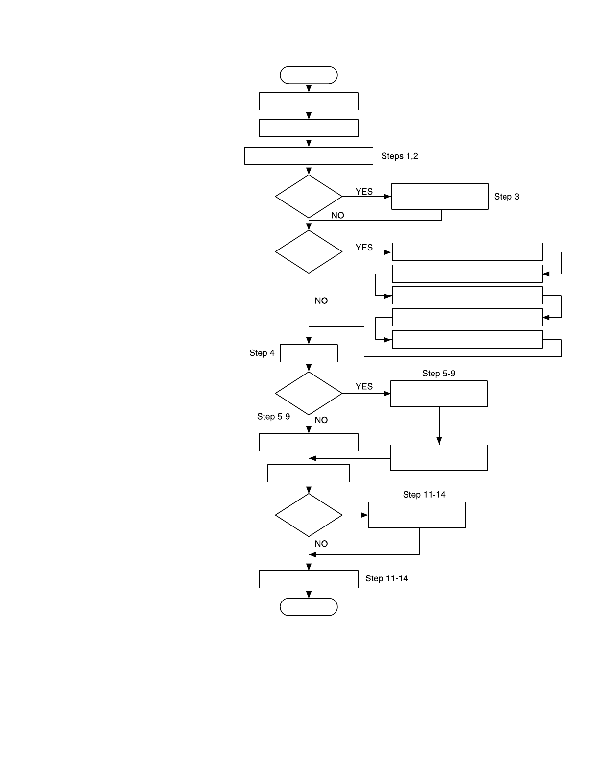
FIGURE 1-1.
Mass ProBar Installation Chart
Start.
Unpack Mass ProBar.
Review Product
Manual.
Review Section 2 to verify proper location.
Introduction
Hazardous
Location?
Bench
Configure?
Verify model
indicated on tag.
Remote
Mounted
Electronics?
Install flowmeter according to
Sections 3 - 7, based on model.
Wire Mass ProBar according
to Section 11.
Review Appendix C.
Configure write-protect and failure
alarms according to Section 9.
Connect the bench power supply
according to Section 11.
Connect the Mass ProBar to a PC
according to Section 10.
Perform ben ch co nfigu ration ta sks
according to Secti on 10.
(Optional) Perform ben ch calibration
tasks according to S ection 10.
Install hardware according to
Sections 3 - 7, based on model.
Install electronics acc ording
to Section 8.
Remote
Mounted
Electronics?
Commission Mass ProBar
according to Section 12.
Finish.
Commission Mass ProB ar
according to Section 13.
1-3

Mass ProBar Flowmeter
The following list is a summary of the steps required to complete a
Mass ProBar flowmeter installation. If this is an entirely new
installation, begin with step 1. If the mounting is already in place,
verify that the hole size and the fittings match the recommended
specifications, and begin with step 5.
1. Determine where the Mass ProBar is to be placed within the
piping system.
2. Establish the proper orientation as determined by the intended
Mass ProBar service for the flowmeter.
3. Review Appendix C: Approval Drawings if the flowmeter is
located in a hazardous location.
4. Confirm the Mass ProBar configuration.
5. Drill the correct size hole in the pipe.
• Fo r Mass ProBar models equipped with opposite-side support,
drill a second, identical hole 180° from the first hole.
6. Weld the mounting, and clean the burrs and welds.
7. Measure the pipe’s internal diameter (ID), preferably at 1 x ID
from the hole (upstream or downstream).
NOTE
Providing the pipe internal diameter at the time of purchase is
necessary to maintain published flowmeter accuracy.
8. Check the fit-up of the Mass ProBar assembly to the pipe.
9. Install the flowmeter.
10. Wire the Mass ProBar electronics.
11. Supply power to the flowmeter.
12. Perform a trim for mounting effects.
13. Check for leaks.
14. Commission the Mass ProBar.
1-4

Section
2 Installation Location
and Orientation
This section describes the orientation, location, and alignment limits
for installing the Mass ProBar flowmeter . Read it thoroughly before any
installation is performed.
SAFETY MESS AGES
Instructions and procedures in this section may require special
precautions to ensure the safety of the personnel performing the
operations. Please refer to the following safety messages before
performing any operation in this section.
Explosions could result in death or serious injury:
• Do not remove the transmitter cov er in explosive atmospheres when the circuit is alive.
• Before connecting a HART-based communicator in an explosive atmosphere, make
sure the instruments in the loop are installed in accordance with intrinsically safe or
non-incendive field wiring practices.
• Verify that the operat ing atmosphere of the transmitter is consistent with the
appropriate hazardous locations certifications.
• Both transmitter covers must be fully engaged to meet explosion-proof requirements.
Failure to follow these installation guidelines could result in death or serious injury:
• Make sure only qualified personnel perform the installation.
RECEIVING
AND INSPECTION
MASS PROBAR
CONFIGURATIONS
Mass ProBar flowmeters are available in different models and with
different options, so it is important to inspect and know which model
you have before beginning installation.
Upon receipt of the shipment, check the packing list against the
material received and the purchase order. All items are tagged with a
model number, serial number, and customer tag number. Report any
damage to the carrier.
The Mass ProBar is available in a variety of mounting configurations
and has two methods of electronic mounting: integral mount (or, direct
mount) and remote mount (Figure 2-1 on page 2-2). An integrallymounted Mass ProBar may be shipped with the electronics already
bolted directly to the sensor.
2-1

Mass ProBar Flowmeter
FIGURE 2-1.
Mass ProBar Mounting Configuration
Examples: A (Integral Mount)
and B (Remote Mount).
STRUCTURAL
LIMITATIONS
FUNCTIONAL
LIMITATIONS
Mass ProBar
Electronics
AB
Mass ProBar
Sensor
Mounting
Configuration
Mass ProBar
Sensor
Mass ProBar
Electronics
Mounting
Configuration
Structural limitations are printed on the Mass ProBar sensor tag.
CAUTION
Exceeding the Mass ProBar structural limitations may cause the
sensor to fail.
The Mass ProBar best produces accurate and repeatable flow
measurement under the following conditions:
• The maximum differential pressure, as printed on the tag
attached to the Mass ProBar, is not exceeded.
• The Mass ProBar is not used for two-phase flow or for steam
service below saturation temperature.
Install the Mass ProBar in the correct location within the piping branch
to prevent measurement inaccuracies caused by flow disturbances.
8900-8900M01A, 8900_28A
FIGURE 2-2.
Permissible Misalignment for
the Mass ProBar.
Mass ProBar installation allows for a maximum misalignment of
3 degrees, as illustrated in Figure 2-2. Misalignment beyond 3
degrees will cause errors in flow measurement.
3° max.
3° max. 3° max.
8900-8900M08A
2-2

Installation Location and Orientation
Straight Run Requirements
Use Table 2-1 to determine the proper Mass ProBar straight
run requirements.
NOTES
For gas service, multiply values from Table 2-1 by 1.5.
If longer lengths of straight run are available, position the Mass
ProBar where 80% of the run is upstream of the Mass ProBar and
20% is downstream.
Information contained in this manual applies to circular pipes only.
Consult the factory for instructions regarding Mass ProBar use in
square or rectangular ducts.
Straightening vanes may be used to reduce the required straight run
length and will improve performance.
Row 6 in Table 2-1 applies to gate, globe, plug, and other throttling
valves that are partially opened. If a “through-type” valve will
remain open, use the values shown in Row 5. Refer to Row 6 for the
straight run requirements of a Mass ProBar located downstream
of the control valve.
2-3

Mass ProBar Flowmeter
TABLE 2-1. Straight Run Requirements.
Upstream dimension
Without vanes With vanes
Downstream
Dimensions
1.
2.
3.
4.
In plane AOut of
8
1295-0573B
1295-0573C
1295-0573D
–
11
–
23
–
12
plane A
10
–
16
–
28
–
12
A’ C C’
–
8
–
8
–
8
–
–
4
–
4
–
4
–
–
4
–
4
–
4
–
4
4
4
4
4
4
4
5.
6.
1295-0573E
1295-0573F
1295-0573G
18
30
–
–
–
18
30
–
–
–
8
–
8
–
8
4
–
4
–
4
4
–
4
–
4
4
4
4
4
4
2-4

Installation Location and Orientation
ENVIRONMENTAL
CONSIDERATIONS
Access Requirements
Process Fl ange Orie nta ti o n
Housing Rotation
Terminal Side of
Electronics Housing
Mount the Mass ProBar in a location with minimal ambient
temperature changes. Section 17: Specifications and Reference
Data lists the Mass ProBar temperature operating
limits. Mount the Mass ProBar to avoid vibration and mechanical
shock, and to avoid external contact with corrosive materials.
When choosing an installation location and position, take into account
the need for access to the Mass ProBar.
The process flanges must be oriented so that process connections can be
made. In addition, consider the possible need for a testing or calibration
input. Drain/vent valves must be oriented so that the process fluid is
directed away from technicians when the valves are used.
The electronics housing may be rotated to improve field access to the
two compartments. To rotate the housing less than 90 degrees, release
the housing rotation set screw and turn the housing not more than
90 degrees from the orientations shown in Figure 2-3 below. To rotate
the housing greater than 90 degrees, consult factory. Rotating the
housing greater than 90 degrees without performing the disassembly
procedure may damage the Mass ProBar sensor module.
• Wiring connections are made through the conduit openings on the
top side of the housing.
• The field terminal side is marked on the electronics housing.
• Mount the Mass ProBar so that the terminal side is accessible. A
0.75-in. clearance is required for cover removal.
• Install a conduit plug on the unused side of the conduit opening.
Circuit Side of
Electronics Housing
FIGURE 2-3.
Mass ProBar Housing Orientation.
Terminal Side of
Electronics Housing
Circuit Side of
Electronics Housing
The circuit compartment should not routinely need to be opened when
the unit is in service; however, provide 0.75-in. clearance if possible to
allow access.
• Wiring connections are made through the conduit openings on the
top side of the housing.
• The field terminal side is marked on the electronics housing.
• Mount the transmitter so that the terminal side is accessible. A
0.75-inch clearance is required for cover removal.
• Install a conduit plug on the unused side of the conduit opening.
The circuit compartment should not routinely need to be opened when
the unit is in service; however, provide 0.75 inches clearance if possible
to allow access.
2-5

Mass ProBar Flowmeter
MASS PROBAR
ORIENTATION
Horizontal Pipe:
Liquid or Steam Application
When selecting a Mass ProBar location, proper venting or draining
must be considered.
• Liquid or Steam Applications: Locate the mass proBar head below
the pipe. See Figures 2-2 and 2-5.
For liquid applications, mount the side drain/vent valve
upward to allow the gases to vent. In steam applications,
fill the lines with water to prevent contact of the live
steam with the electronics. Condensate chambers are
not needed because the volumetric displacement of the
electronics is negligible.
• Air and Gas Applications: Locate the Mass ProBar head above the
pipe. See Figures 2-3 and 2-4.
For air and gas applications, mount the drain/vent valve
down to allow any accumulated liquid to drain.
Mass ProBar instrument head connections differ on horizontal and
vertical pipes. Consult your specification head code number to
confirm the proper pipe orientation of the Mass ProBar.
Due to the possibility of air getting trapped in the probe, the Mass
ProBar should be located per the drawing below. The area between 0°
and 50° (50° angle) should not be used unless full bleeding of air from
the probe is possible. Figure 2-4 illustrates the recommended location
of the flowmete r.
FIGURE 2-4.
Liquid or Steam Application in a
Horizontal Pipe.
50°
80° (Recommended Zone)
50°
8900-8900M02A
2-6

Installation Location and Orientation
Horizontal Pipe:
Air and Gas Applications
FIGURE 2-5.
Air and Gas Applications in a
Horizontal Pipe.
Vertical Pipe: Liquid, Air,
Gas, and Steam Applications
The Mass ProBar should be located on the upper half of the pipe, at least 30°
above the horizontal line . Figure 2-5 illustra tes the recommended location of
the flowmeter .
120° (Recommended
Zone)
30°
30°
The Mass ProBar can be installed i n any positi on around the c ircumferen ce
of the pipe, provided the vents are positioned properly for bleeding or
venting. Vertical pipe instal lations requi re more fr equent bl eeding or
venting depending on the location. Figure 2-6 illustra tes the rec ommended
location of the flowmeter.
8900-8900M10A
FIGURE 2-6.
Liquid, Air, and Gas Applications
in a Vertical Pipe.
FIGURE 2-7.
Steam Service in a Vertical Pipe.
50°
80° (Recommended Zone)
50°
Remote mounting is required for steam installations; see Figure 2-7.
Mass ProBar
Remote Head
8900-8900M09A
Instrument Valve
8900-8900_04A
2-7

Mass ProBar Flowmeter
2-8

Section
3 Hardware Installation for
Mass ProBar Regular
MASS PROBAR MODELS:
MBR+15S/16S
MBR+25S/26S
MBR+35S/36S
MBR+45S/46S
SAFETY MESS AGES
This section provides hardware installation instructions for the Mass
ProBar Regular (Threaded, Pak-Lok) for service in either a horizontal
or vertical pipe. Installation procedures are similar for all services.
Service-specific instructions are provided where necessary; otherwise,
all instructions in this section apply to all services.
If remote mounting of the electronics is required, use this section for
hardware installation. Then, see Section 8: Mass ProBar Remote
Mounting for electronics installation.
• The direct mount maximum service temperature is
500 °F (260 °C).
• The electronics must be remote mounted when service
temperatures exceed 500 °F (260 °C).
• Mass ProBar models with a sensor size of 15 or 16 require remote
mounted electronics. After installing the sensor, see Section 8:
Mass ProBar Remote Mounting for instructions on installing
the electronics.
• Mass ProBar models with a sensor size of 45 or 46 are shipped
with a packing guide cover instead of a compression nut.
Instructions and procedures in this section may require special
precautions to ensure the safety of the personnel performing the
operations. Please refer to the following safety messages before
performing any operation in this section.
Explosions could result in death or serious injury:
• Do not remove the transmitter cov er in explosive atmospheres when the circuit is alive.
• Before connecting a HART-based communicator in an explosive atmosphere, make
sure the instruments in the loop are installed in accordance with intrinsically safe or
non-incendive field wiring practices.
• Verify that the operat ing atmosphere of the transmitter is consistent with the
appropriate hazardous locations certifications.
• Both transmitter covers must be fully engaged to meet explosion-proof requirements.
Failure to follow these installation guidelines could result in death or serious injury:
• Make sure only qualified personnel perform the installation.
3-1

Mass ProBar Flowmeter
MASS PROBAR REGULAR
COMPONENTS
FIGURE 3-1.
Mass ProBar Regular Components .
RTD
Connector
Mass ProBar
Electronics
Integral 3-Valve
Manifold Head
Figure 3-1 identifies the components of the Mass ProBar Regul ar. The
flowmeter is shown in this position for hardware clarity; see the actual
installation instructions for proper positioning of the flowmeter.
RTD Body
Housing
Weld Coupling with
Shaped Support Ring
Pipe Supplied
Packing
Follower
Compression
Nut
Packing
Rings (3)
WeldLock
Ring
Adapter
Body
by Customer
Flow Sensor
(316L)
Weld Fitting
(opposite-side
support)
Support
Plug
8900-8900M11A
STEP 1:
DETERMINE THE PROPER
MASS PROBAR
ORIENTATION
Liquid Service in a
Horizontal Pipe
FIGURE 3-2.
Liquid Service in a Horizontal Pipe.
Orientation of the Mass ProBar depends upon two factors: the
orientation of the pipe that will receive the flowmeter, and the service
that uses the pipe. The following sections provide illustrations of the
possible pipe orientations and services. After determining the
flowmeter’s orientation, proceed with step 2 on page 3-5.
Install the flowmeter within 40 degrees of the vertical axis to prevent
air from becoming entrapped wi thin the probe . Do not position the Mass
ProBar within 50 degrees of the horizontal axis unless full bleeding of
air from the probe is possible. Figure 3-2 illustrates the recommended
location for the Mass ProBar when used with liquid service.
50°50°
80° (Recommended Zone)
8900-8900M09A
3-2

Hardware Installation for Mass ProBar Regular
Gas Service in a
Horizontal Pipe
FIGURE 3-3.
Gas Service in a Hori zontal Pipe.
Steam Ser vice in a
Horizontal Pipe
Install the flowmeter in the upper half of the pipe, but not within 30
degrees of the horizontal axis, as shown in F igure 3-3 below. This
orientation prevents condensate from becoming entrapped in the
sensor probe.
120° (Recommended
Zone)
30° 30°
8900-8900M10A
Install the flowmeter within 40 degrees of the vertical axis to prevent
air from becoming entrapped within the sensor probe. Do not position
the Mass ProBar within 50 degrees of the horizontal axis unless full
bleeding of air from the probe is possible. Figure 3-4 illustrates
the recommended location for the Mass ProBar when used
with steam servic e.
FIGURE 3-4.
Steam Service in a Horizontal Pipe.
50°
80° (Recommended Zone)
50°
8900-8900M09A
3-3

Mass ProBar Flowmeter
Liquid or Gas Service
in a Vertical Pipe
FIGURE 3-5.
Liquid or Gas Service
in a Vertical Pipe.
Steam Ser vice in a
Vertical Pipe
FIGURE 3-6.
Steam Service in a Vertical Pipe.
Install the flowmeter anywhere around the circumference of the pipe,
as shown in Figure 3-5. The Mass ProBar electronics run in the
opposite direction of the process piping.
FLOW
360°
Install the flowmeter anywhere around the circumference of the pipe,
as shown in Figure 3-6. The Mass ProBar electronics must be remote
mounted. See Section 8: Mass ProBar Remote Mounting
for instructions.
Mass ProBar
Remote Head
8900-8900M13A
SHIPPING NOTE
Instrument Valve
8900-8900_04A
All Mass ProBar Regular models are shipped with the Mass ProBar
sensor pre-assembled and the Pak-Lok nut, follower, and lock ring in
place. The factory-supplied weld fitting with support ring is required to
install the Mass ProBar. To prevent injury, remove pressure and drain
pipe before installing or removing the sensor.
3-4

Hardware Installation for Mass ProBar Regular
STEP 2:
DRILL THE HOLE IN
THE PIPE
Drill a Hole for
Opposite-Side Support
Follow the steps below to drill the hole in the pipe.
1. Depressurize and drain the pipe.
2. Select the location for the hole you are about to drill.
Select a location anywhere around the circumference of the pipe
for vertical pipes.
For horizontal pipes, the hole location depends upon the service
for which the Mass ProBar is to be used:
• Liquid service: drill the hole along the bottom of the pipe
• Gas service: drill the hole along the top of the pipe
• Steam service: drill the hole along the bottom of the pipe
3. Determine the diameter of the hole to be drilled. Use the chart
in Figure 3-7.
4. After the hole is drilled, deburr the hole on the inside of the pipe.
A second hole must be drilled for the opposite-side support weld
coupling if opposite-side support is supplied. This hole must be the
same diameter as the first hole; place it directly opposite the first hole
so that the sensor can pass completely through the pipe. Use the
following steps to find the location for the second hole:
1. Wrap a piece of soft wire or string around the pipe to
measure the pipe’s circumference.
2. Remove the wire or string and measure half of the
circumference length.
3. Re-wrap the half-length around the pipe from the
center of the first hole.
4. Mark the center of what will become the second hole,
as shown in Figure 3-7.
FIGURE 3-7.
Sensor Size/Hole Diameter Chart.
Note: Drill the hole 180 degrees from the first hole
for opposite-side support models.
Sensor Diameter (in.)
15/16
25/26
35/36
45/46
Drill the appropriate
diameter hole through
the pipe wall.
5. Deburr the drilled hole on the inside of the pipe.
Drill
7
/16
7
/8
1-5/16
2-1/8
8900-8900_15A
3-5

Mass ProBar Flowmeter
STEP 3:
TACK WELD THE
FITTINGS TO THE PIPE
FIGURE 3-8.
Tack Weld the Fittings to the Pipe.
Fol low these steps to tack weld the fittings to the pipe:
1. Insert the Mass ProBa r asse mbly into the fa ctor y-s upplied
weld fitting (with integral support ring), then into the hole.
2. Align the head and electronics so they are parallel with
the ground.
3. Tack weld the fitting(s) to the pipe and remove the Mass ProBar .
See Figure 3-8 below.
The support ring shall be in-line or
parallel to plane of pipe as shown.
8900-8900V20A
NOTE
The larger radius in Figure 3-8 must be parallel to the centerline of
the pipe.
To protect the weld fitting threads from weld splatter, wrap the
factory-supplied heavy aluminum foil around the threads before
welding, or use a thread protector cap, as shown in Figure 3-9.
Be sure to allow the mounting to cool or serious burns may occur.
FIGURE 3-9.
Protect Threads from Weld Splatter:
A (Liquid or Steam Ser vice) and
B (Gas Service).
AB
Protect
Threads
from Weld
Splatter
8900-8900_16A
3-6
 Loading...