

Page 1
Instruction Manual
IM-106-350C, Rev 2.2
July 2008
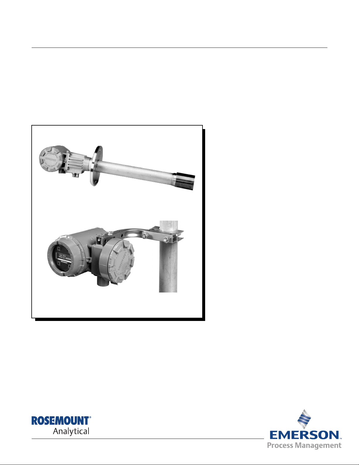
Oxymitter 5000 Hazardous Area
Oxygen Transmitter
http://www.raihome.com
Page 2

Page 3

HIGHLIGHTS OF CHANGES
Effective September 2006 Rev 2.0
Page Summary
General Reformatted entire manual from a two column layout. Replaced SPS 4000 information
with SPS 4001B information. Removed all references to JIS specifications. Added
information pertaining to the Local Operator Interface (LOI). Added information pertaining
to the remote electronics option.
Page TOC-4 Removed List of Illustrations and List of Tables from the table of contents in Rev 1.4.
Page i Moved from backside of cover in Rev 1.4.
Page 1-2 Updated Figure 1-1, Typical System Package to show SPS 4001B and remote electronics.
Page 1-5 Updated Figure 1-2, Hazardous Area Oxymitter 5000 Autocalibration System Options to
show the SPS 4001B.
Page 1-6 Added Figure 1-3, Membrane Keypad and Figure 1-4, Local Operator Interface (LOI).
Added step 4 under System Features
Page 1-7 Removed step 6 under System Features from Rev 1.6.
Page 1-10 Added Figure 1-7, Typical System Installation – Oxymitter 5000 with Remote Electronics.
Page 1-11 Added Mounting and Operation instructions for the SPS 4001B.
Page 1-14 thru 1-15 Updated the specifications table and added applicable certifications regarding the
Hazardous Area Oxymitter 5000.
Page 1-16 Updated Table 1-1, Product Matrix.
Page 1-18 Removed Table 1-4, Single Probe Autocalibration Sequencer Coding from Rev 1.4.
Page 2-1 Added first Warning.
Page 2-2 Added first Note.
Page 2-4 Added Figure 2-2, Hazardous Area Oxymitter 5000 Remote Electronics Installation.
Page 2-8 Added third Note.
Page 2-10 Added Figure 2-8, Remote Electronics Mounting and corresponding text.
Page 2-11 Added Note and fifth Warning.
Page 2-12 Added Figure 2-10, Electrical Installation - Hazardous Area Oxymitter 5000 with Integral
Electronics.
Page 2-13 thru 2-14 Added information under Electrical Installation with Remote Electronics.
Page 2-15 Added Figure 2-10, Electrical Installation - Hazardous Area Oxymitter 5000 with Remote
Electronics.
Page 2-16 Added information regarding the installation of the interconnecting cable. Removed Figure
2-7, Terminal Block from Rev 1.4.
Page 2-18 Added body text under IMPS 4000 Connections and SPS4001B Connections.
Page 3-2 Added Caution.
Page 4

HIGHLIGHTS OF CHANGES (CONTINUED)
Effective September 2006 Rev 2.0 (Continued)
Page Summary
Page 4-1 thru 4-6 Added Section 4, Configuration of Hazardous Area Oxymitter 5000 with LOI.
Page 5-1 thru 5-4 Pages 3-6 thru 3-8 in Section 3, Startup and Operation of Rev 1.4 was moved to Section 5,
Startup and Operation of Oxymitter 5000 with Membrane Keypad.
Page 6-1 thru 6-10 Added Section 6, Startup and Operation of Hazardous Area Oxymitter 5000 with LOI.
Page 7-1 Added body text under Overview.
Page 7-2 Added Figure 7-1, O2 Sensor mV Reading vs. % O2 at 736°C (Reference Air, 20.9% O2).
Page 7-4 Added Figure 7-2, Diagnostic LEDs.
Page 7-7 thru 7-21 Added the LOI in Figures 7-3 thru 7-17 with descriptive text to accompany each figure.
Page 7-22 and 7-23 Added text and Figure 7-18, Probe Leakage Paths.
Page 8-0 Moved the "Calibration Record for Rosemount Analytical in Situ O2 Probe", from the back
of the section to the front.
Page 8-6 and 8-7 Added information under the Calibration with LOI heading.
Page 8-7 Removed information regarding LED Status Indicators and Table 4-1, Diagnostic/Unit
Alarms from Rev 1.4.
Page 8-8 thru 8-23 Updated procedural steps throughout section.
Page 8-9 Added step 3 under Entire Replacement of Electronics (with Housing). Removed Figure
4-4, Terminal Block from Rev 1.4.
page 8-10 Updated Figure 8-3, Hazardous Area Oxymitter 5000 with Integral Electronics - Exploded
View, to show the LOI module and Window Cover.
Page 8-11 Added Figure 8-4, Hazardous Area Oxymitter 5000 with Remote Electronics - Exploded
View.
Page 8-16 Added third Warning.
Page A-1 thru A-22 Moved Safety Instructions P-3 thru P-12 from the preface in Rev 1.4 to Appendix A in Rev
2.0.
Page B-1 Moved Section 10, Return of Material from Rev 1.4 to Appendix B in Rev 2.0.
Page C-1 thru C-6 Moved Appendix A to Appendix C in Rev 2.0.
Page D-1 thru D-10 Moved Appendix B to Appendix D in Rev 2.0.
Page E-1 Moved Appendix C to Appendix E in Rev 2.0.
Effective January 2007 Rev 2.1
Page Summary
General Revised reference air specifications to read 0.25 l/min (0.5 scfh) throughout the manual.
Page 7-1 thru 7-6 Added section 7.
Page 8-22 Added the paragraph and procedural steps after 'Heater Not Open, but Unable to Reach
736°C Setpoint.'
Page 11-1 Added Model 375 Handheld Communicator information.
Page 5

HIGHLIGHTS OF CHANGES (CONTINUED)
Effective January 2007 Rev 2.1 (Continued)
Page Summary
Page 11-2 Added Asset Management Solutions (AMS) information.
Page A-2 thru A-24 Added note 11 to the safety data section. Added new language translations.
Page B-1 Updated the return of materials address.
Back cover Updated the address blocks.
Effective July 2008 Rev. 2.2
Page Summary
Page 6-4 Added note regarding cleaning the LOI screen before use.
Page 6

Page 7

Instruction Manual
IM-106-350C, Rev 2.2
July 2008
Hazardous Area Oxymitter 5000
Table of Contents
Essential Instructions. . . . . . . . . . . . . . . . . . . . . . . . . . . . . . . . . . . . . . . . i
Preface . . . . . . . . . . . . . . . . . . . . . . . . . . . . . . . . . . . . . . . . . . . . . . . . . .ii
Definitions . . . . . . . . . . . . . . . . . . . . . . . . . . . . . . . . . . . . . . . . . . . . . . . .ii
Symbols. . . . . . . . . . . . . . . . . . . . . . . . . . . . . . . . . . . . . . . . . . . . . . . . . .ii
Oxymitter 5000 with Fieldbus Communications. . . . . . . . . . . . . . . . . . . iii
SECTION 1
Description and
Specifications
SECTION 2
Installation
Component Checklist. . . . . . . . . . . . . . . . . . . . . . . . . . . . . . . . . . . . . . 1-1
System Overview. . . . . . . . . . . . . . . . . . . . . . . . . . . . . . . . . . . . . . . . . 1-1
Scope . . . . . . . . . . . . . . . . . . . . . . . . . . . . . . . . . . . . . . . . . . . . . . . 1-1
Foundation Fieldbus Technology . . . . . . . . . . . . . . . . . . . . . . . . . . 1-3
System Description. . . . . . . . . . . . . . . . . . . . . . . . . . . . . . . . . . . . . 1-3
System Configuration . . . . . . . . . . . . . . . . . . . . . . . . . . . . . . . . . . . 1-4
System Features . . . . . . . . . . . . . . . . . . . . . . . . . . . . . . . . . . . . . . 1-5
Handling the Oxymitter. . . . . . . . . . . . . . . . . . . . . . . . . . . . . . . . . . 1-7
System Considerations. . . . . . . . . . . . . . . . . . . . . . . . . . . . . . . . . . 1-7
IMPS 4000 (Optional) . . . . . . . . . . . . . . . . . . . . . . . . . . . . . . . . . . . . 1-11
SPS 4001B (Optional) . . . . . . . . . . . . . . . . . . . . . . . . . . . . . . . . . . . . 1-11
Mounting. . . . . . . . . . . . . . . . . . . . . . . . . . . . . . . . . . . . . . . . . . . . 1-11
Operation . . . . . . . . . . . . . . . . . . . . . . . . . . . . . . . . . . . . . . . . . . . 1-11
Probe Options . . . . . . . . . . . . . . . . . . . . . . . . . . . . . . . . . . . . . . . . . . 1-11
Diffusion Elements . . . . . . . . . . . . . . . . . . . . . . . . . . . . . . . . . . . . 1-11
Abrasive Shield Assembly . . . . . . . . . . . . . . . . . . . . . . . . . . . . . . 1-12
Specifications. . . . . . . . . . . . . . . . . . . . . . . . . . . . . . . . . . . . . . . . . . . 1-14
Mechanical Installation . . . . . . . . . . . . . . . . . . . . . . . . . . . . . . . . . . . . 2-2
Selecting Location . . . . . . . . . . . . . . . . . . . . . . . . . . . . . . . . . . . . . 2-2
Probe Installation . . . . . . . . . . . . . . . . . . . . . . . . . . . . . . . . . . . . . . 2-2
Remote Electronics Installation . . . . . . . . . . . . . . . . . . . . . . . . . . 2-10
Electrical Installation with Integral Electronics. . . . . . . . . . . . . . . . . . 2-10
Connect Line Voltage . . . . . . . . . . . . . . . . . . . . . . . . . . . . . . . . . . 2-11
Electrical Installation with Remote Electronics . . . . . . . . . . . . . . . . . 2-13
Connect Line Voltage . . . . . . . . . . . . . . . . . . . . . . . . . . . . . . . . . . 2-14
Calibration Handshake Logic I/O . . . . . . . . . . . . . . . . . . . . . . . . . 2-14
Install Interconnecting Cable . . . . . . . . . . . . . . . . . . . . . . . . . . . . 2-16
Pneumatic Installation . . . . . . . . . . . . . . . . . . . . . . . . . . . . . . . . . . . . 2-17
Calibration Gas. . . . . . . . . . . . . . . . . . . . . . . . . . . . . . . . . . . . . . . 2-18
IMPS 4000 Connections . . . . . . . . . . . . . . . . . . . . . . . . . . . . . . . . . . 2-18
SPS 4001B Connections . . . . . . . . . . . . . . . . . . . . . . . . . . . . . . . . . . 2-18
SECTION 3
Configuration of
Hazardous Area
Oxymitter 5000 with
Membrane Keypad
Verify Installation . . . . . . . . . . . . . . . . . . . . . . . . . . . . . . . . . . . . . . . . . 3-1
Mechanical Installation . . . . . . . . . . . . . . . . . . . . . . . . . . . . . . . . . . 3-1
Terminal Block Wiring. . . . . . . . . . . . . . . . . . . . . . . . . . . . . . . . . . . 3-1
Hazardous Area Oxymitter 5000 Configuration . . . . . . . . . . . . . . . 3-2
Logic I/O . . . . . . . . . . . . . . . . . . . . . . . . . . . . . . . . . . . . . . . . . . . . . . . 3-4
Recommended Configuration. . . . . . . . . . . . . . . . . . . . . . . . . . . . . 3-6
TOC-1
Page 8

Hazardous Area Oxymitter 5000
Instruction Manual
IM-106-350C, Rev 2.2
July 2008
SECTION 4
Configuration of
Hazardous Area
Oxymitter 5000 with LOI
SECTION 5
Startup and Operation of
Hazardous Area
Oxymitter 5000 with
Membrane Keypad
SECTION 6
Startup and Operation of
Hazardous Area
Oxymitter 5000 with LOI
Verify installation . . . . . . . . . . . . . . . . . . . . . . . . . . . . . . . . . . . . . . . . . 4-1
Mechanical Installation . . . . . . . . . . . . . . . . . . . . . . . . . . . . . . . . . . 4-1
Terminal Block Wiring. . . . . . . . . . . . . . . . . . . . . . . . . . . . . . . . . . . 4-1
Hazardous Area Oxymitter 5000 Configuration . . . . . . . . . . . . . . . 4-2
Logic I/O . . . . . . . . . . . . . . . . . . . . . . . . . . . . . . . . . . . . . . . . . . . . . . . 4-4
Recommended Configuration. . . . . . . . . . . . . . . . . . . . . . . . . . . . . 4-5
Power Up. . . . . . . . . . . . . . . . . . . . . . . . . . . . . . . . . . . . . . . . . . . . . . . 5-1
Operation. . . . . . . . . . . . . . . . . . . . . . . . . . . . . . . . . . . . . . . . . . . . . . . 5-2
Overview. . . . . . . . . . . . . . . . . . . . . . . . . . . . . . . . . . . . . . . . . . . . . 5-2
Power Up. . . . . . . . . . . . . . . . . . . . . . . . . . . . . . . . . . . . . . . . . . . . . . . 6-1
Start Up Oxymitter 5000 Calibration . . . . . . . . . . . . . . . . . . . . . . . . . . 6-3
Navigating the Local Operator Interface . . . . . . . . . . . . . . . . . . . . . . . 6-3
Overview. . . . . . . . . . . . . . . . . . . . . . . . . . . . . . . . . . . . . . . . . . . . . 6-3
Lockout. . . . . . . . . . . . . . . . . . . . . . . . . . . . . . . . . . . . . . . . . . . . . . 6-3
LOI Key Designations . . . . . . . . . . . . . . . . . . . . . . . . . . . . . . . . . . . . . 6-4
LOI Menu Tree. . . . . . . . . . . . . . . . . . . . . . . . . . . . . . . . . . . . . . . . . . . 6-4
Hazardous Area Oxymitter 5000 Setup at the LOI . . . . . . . . . . . . . . . 6-6
LOI Installation. . . . . . . . . . . . . . . . . . . . . . . . . . . . . . . . . . . . . . . . . . . 6-9
Oxymitter 5000 Test Points . . . . . . . . . . . . . . . . . . . . . . . . . . . . . . . . . 6-9
SECTION 7
Model 375 Handheld
Communicator
SECTION 8
Troubleshooting
SECTION 9
Maintenance and Service
Overview . . . . . . . . . . . . . . . . . . . . . . . . . . . . . . . . . . . . . . . . . . . . . . . 7-1
Fieldbus Terminal Block Connections . . . . . . . . . . . . . . . . . . . . . . . . . 7-1
Off-Line and On-Line Operations. . . . . . . . . . . . . . . . . . . . . . . . . . . . . 7-2
Logic I/O Configurations . . . . . . . . . . . . . . . . . . . . . . . . . . . . . . . . . . . 7-3
Fieldbus Menu Tree. . . . . . . . . . . . . . . . . . . . . . . . . . . . . . . . . . . . . . . 7-4
FOUNDATION Fieldbus O2 CAL Method . . . . . . . . . . . . . . . . . . . . . . 7-5
Overview . . . . . . . . . . . . . . . . . . . . . . . . . . . . . . . . . . . . . . . . . . . . . . . 8-1
General . . . . . . . . . . . . . . . . . . . . . . . . . . . . . . . . . . . . . . . . . . . . . . . . 8-3
Alarm Indications . . . . . . . . . . . . . . . . . . . . . . . . . . . . . . . . . . . . . . . . . 8-3
Alarm Contacts . . . . . . . . . . . . . . . . . . . . . . . . . . . . . . . . . . . . . . . . . . 8-4
Identifying And Correcting Alarm Indications. . . . . . . . . . . . . . . . . . . . 8-5
Heater Not Open, but Unable to Reach 736°C Setpoint . . . . . . . . . . 8-22
Calibration Passes but Still Reads Incorrectly. . . . . . . . . . . . . . . . . . 8-22
Overview . . . . . . . . . . . . . . . . . . . . . . . . . . . . . . . . . . . . . . . . . . . . . . . 9-1
Calibration with Keypad. . . . . . . . . . . . . . . . . . . . . . . . . . . . . . . . . . . . 9-1
Automatic Calibration . . . . . . . . . . . . . . . . . . . . . . . . . . . . . . . . . . . 9-2
Semi-Automatic Calibration . . . . . . . . . . . . . . . . . . . . . . . . . . . . . . 9-3
Manual Calibration with Membrane Keypad. . . . . . . . . . . . . . . . . . 9-4
FOUNDATION Fieldbus O2 CAL Method . . . . . . . . . . . . . . . . . . . . . . 9-6
Calibration with LOI . . . . . . . . . . . . . . . . . . . . . . . . . . . . . . . . . . . . . . . 9-6
Hazardous Area Oxymitter 5000 Repair . . . . . . . . . . . . . . . . . . . . . . . 9-8
Removal and Replacement of Probe . . . . . . . . . . . . . . . . . . . . . . . 9-8
Replacement of Entire Electronics (with Housing) . . . . . . . . . . . . . 9-9
Electronic Assembly Replacement. . . . . . . . . . . . . . . . . . . . . . . . 9-12
Terminal Block Replacement . . . . . . . . . . . . . . . . . . . . . . . . . . . . 9-14
TOC-2
Page 9

Instruction Manual
IM-106-350C, Rev 2.2
July 2008
Hazardous Area Oxymitter 5000
Fuse Replacement . . . . . . . . . . . . . . . . . . . . . . . . . . . . . . . . . . . . 9-14
Entire Probe Replacement (Excluding Electronics) . . . . . . . . . . . 9-15
Heater Strut Replacement . . . . . . . . . . . . . . . . . . . . . . . . . . . . . . 9-16
Cell Replacement . . . . . . . . . . . . . . . . . . . . . . . . . . . . . . . . . . . . . 9-18
Ceramic Diffusion Element Replacement. . . . . . . . . . . . . . . . . . . 9-21
Contact and Thermocouple Assembly Replacement . . . . . . . . . . 9-22
SECTION 10
Replacement Parts
SECTION 11
Optional Accessories
APPENDIX A
Safety Data
APPENDIX B
Return of Material
APPENDIX C
Fieldbus Parameter
Description
APPENDIX D
Analog Input (AI)
Function Block
Probe Replacement Parts . . . . . . . . . . . . . . . . . . . . . . . . . . . . . . . . . 10-1
Electronics Replacement Parts . . . . . . . . . . . . . . . . . . . . . . . . . . . . . 10-4
Model 375 Handheld Communicator. . . . . . . . . . . . . . . . . . . . . . . . . 11-1
Asset Management Solutions (AMS). . . . . . . . . . . . . . . . . . . . . . . . . 11-2
By-Pass Packages. . . . . . . . . . . . . . . . . . . . . . . . . . . . . . . . . . . . . . . 11-2
IMPS 4000 Intelligent Multiprobe Test Gas Sequencer. . . . . . . . . . . 11-3
SPS 4001B Single Probe Autocalibration Sequencer . . . . . . . . . . . . 11-4
O2 Calibration Gas. . . . . . . . . . . . . . . . . . . . . . . . . . . . . . . . . . . . . . . 11-5
Safety Instructions . . . . . . . . . . . . . . . . . . . . . . . . . . . . . . . . . . . . . . . .A-2
Safety Data Sheet for Ceramic Fiber Products . . . . . . . . . . . . . . . . .A-24
Returning Material . . . . . . . . . . . . . . . . . . . . . . . . . . . . . . . . . . . . . . . .B-1
Fieldbus Parameters . . . . . . . . . . . . . . . . . . . . . . . . . . . . . . . . . . . . . .C-1
Simulation . . . . . . . . . . . . . . . . . . . . . . . . . . . . . . . . . . . . . . . . . . . . . .D-3
Filtering . . . . . . . . . . . . . . . . . . . . . . . . . . . . . . . . . . . . . . . . . . . . . . . .D-4
Signal Conversion . . . . . . . . . . . . . . . . . . . . . . . . . . . . . . . . . . . . . . . .D-5
Direct . . . . . . . . . . . . . . . . . . . . . . . . . . . . . . . . . . . . . . . . . . . . . . .D-5
Indirect . . . . . . . . . . . . . . . . . . . . . . . . . . . . . . . . . . . . . . . . . . . . . .D-5
Indirect Square Root. . . . . . . . . . . . . . . . . . . . . . . . . . . . . . . . . . . .D-5
Block Errors . . . . . . . . . . . . . . . . . . . . . . . . . . . . . . . . . . . . . . . . . . . . .D-5
Modes . . . . . . . . . . . . . . . . . . . . . . . . . . . . . . . . . . . . . . . . . . . . . . . . .D-6
Alarm Detection . . . . . . . . . . . . . . . . . . . . . . . . . . . . . . . . . . . . . . . . . .D-6
Status Handling . . . . . . . . . . . . . . . . . . . . . . . . . . . . . . . . . . . . . . . . . .D-7
Advanced Features . . . . . . . . . . . . . . . . . . . . . . . . . . . . . . . . . . . . . . .D-8
Application Information . . . . . . . . . . . . . . . . . . . . . . . . . . . . . . . . . . . .D-8
Channel . . . . . . . . . . . . . . . . . . . . . . . . . . . . . . . . . . . . . . . . . . . . .D-8
L_TYPE . . . . . . . . . . . . . . . . . . . . . . . . . . . . . . . . . . . . . . . . . . . . .D-8
Scaling . . . . . . . . . . . . . . . . . . . . . . . . . . . . . . . . . . . . . . . . . . . . . .D-8
Application Examples . . . . . . . . . . . . . . . . . . . . . . . . . . . . . . . . . . . . .D-9
Temperature Transmitter . . . . . . . . . . . . . . . . . . . . . . . . . . . . . . . .D-9
Pressure Transmitter used to Measure Level in an Open Tank. .D-10
Differential Pressure Transmitter to Measure Flow . . . . . . . . . . .D-12
Troubleshooting. . . . . . . . . . . . . . . . . . . . . . . . . . . . . . . . . . . . . . . . .D-13
APPENDIX E
PID Function Block
Setpoint Selection and Limiting . . . . . . . . . . . . . . . . . . . . . . . . . . . . . .E-6
Filtering . . . . . . . . . . . . . . . . . . . . . . . . . . . . . . . . . . . . . . . . . . . . . . . .E-6
TOC-3
Page 10

Hazardous Area Oxymitter 5000
Feedforward Calculation . . . . . . . . . . . . . . . . . . . . . . . . . . . . . . . . . . .E-6
Tracking. . . . . . . . . . . . . . . . . . . . . . . . . . . . . . . . . . . . . . . . . . . . . . . .E-6
Output Selection and Limiting . . . . . . . . . . . . . . . . . . . . . . . . . . . . . . .E-7
Bumpless Transfer and Setpoint Tracking. . . . . . . . . . . . . . . . . . . . . .E-7
PID Equation Structures . . . . . . . . . . . . . . . . . . . . . . . . . . . . . . . . . . .E-7
Reverse and Direct Action. . . . . . . . . . . . . . . . . . . . . . . . . . . . . . . . . .E-7
Reset Limiting . . . . . . . . . . . . . . . . . . . . . . . . . . . . . . . . . . . . . . . . . . .E-8
Block Errors . . . . . . . . . . . . . . . . . . . . . . . . . . . . . . . . . . . . . . . . . . . . .E-8
Modes . . . . . . . . . . . . . . . . . . . . . . . . . . . . . . . . . . . . . . . . . . . . . . . . .E-8
Alarm Detection . . . . . . . . . . . . . . . . . . . . . . . . . . . . . . . . . . . . . . . . . .E-9
Status Handling . . . . . . . . . . . . . . . . . . . . . . . . . . . . . . . . . . . . . . . . .E-10
Application Information . . . . . . . . . . . . . . . . . . . . . . . . . . . . . . . . . . .E-10
Closed Loop Control. . . . . . . . . . . . . . . . . . . . . . . . . . . . . . . . . . .E-10
Application Examples . . . . . . . . . . . . . . . . . . . . . . . . . . . . . . . . . . . .E-11
Basic PID Block for Steam Heater Control. . . . . . . . . . . . . . . . . .E-11
Feedforward Control. . . . . . . . . . . . . . . . . . . . . . . . . . . . . . . . . . .E-12
Cascade Control with Master and Slave Loops . . . . . . . . . . . . . .E-13
Cascade Control with Override. . . . . . . . . . . . . . . . . . . . . . . . . . .E-14
Troubleshooting. . . . . . . . . . . . . . . . . . . . . . . . . . . . . . . . . . . . . . . . .E-16
Instruction Manual
IM-106-350C, Rev 2.2
July 2008
TOC-4
Page 11

Instruction Manual
IM-106-350C, Rev 2.2
July 2008
Hazardous Area Oxymitter 5000
Oxymitter Oxygen Transmitters
READ THIS PAGE BEFORE PROCEEDING!
ESSENTIAL INSTRUCTIONS
Emerson Process Management designs, manufactures and tests its products
to meet many national and international standards. Because these
instruments are sophisticated technical products, you MUST properly
install, use, and maintain them to ensure they continue to operate within
their normal specifications. The following instructions MUST be adhered to
and integrated into your safety program when installing, using, and
maintaining Rosemount Analytical products. Failure to follow the proper
instructions may cause any one of the following situations to occur: Loss of
life; personal injury; property damage; damage to this instrument; and
warranty invalidation.
• Read all instructions prior to installing, operating, and servicing the
product.
• If you do not understand any of the instructions, contact your
Emerson Process Management representative for clarification.
• Follow all warnings, cautions, and instructions marked on and
supplied with the product.
• Inform and educate your personnel in the proper installation,
operation, and maintenance of the product.
• Install your equipment as specified in the Installation Instructions
of the appropriate Instruction Manual and per applicable local and
national codes. Connect all products to the proper electrical and
pressure sources.
• To ensure proper performance, use qualified personnel to install,
operate, update, program, and maintain the product.
• When replacement parts are required, ensure that qualified people use
replacement parts specified by Emerson Process Management.
Unauthorized parts and procedures can affect the product's
performance, place the safe operation of your process at risk, and
VOID YOUR WARRANTY. Look-alike substitutions may result in fire,
electrical hazards, or improper operation.
• Ensure that all equipment doors are closed and protective covers
are in place, except when maintenance is being performed by
qualified persons, to prevent electrical shock and personal injury.
http://www.raihome.com
The information contained in this document is subject to change without
notice.
Page 12
Hazardous Area Oxymitter 5000
RISKOFELECTRICAL SHOCK
WARNING:REFER TOINSTRUCTIONMANUAL
PROTECTIVECONDUCT OR TERMINAL
EARTH(GROUND) TERMINAL
:
:
:
:
Instruction Manual
IM-106-350C, Rev 2.2
July 2008
PREFACE
DEFINITIONS
The purpose of this manual is to provide information concerning the
components, functions, installation and maintenance of the Oxymitter 5000
Hazardous Area Oxygen Transmitter.
Some sections may describe equipment not used in your configuration. The
user should become thoroughly familiar with the operation of this module
before operating it. Read this instruction manual completely.
The following definitions apply to WARNINGS, CAUTIONS, and NOTES
found throughout this publication.
Highlights an operation or maintenance procedure, practice, condition, statement, etc. If not
strictly observed, could result in injury, death, or long-term health hazards of personnel.
Highlights an operation or maintenance procedure, practice, condition, statement, etc. If not
strictly observed, could result in damage to or destruction of equipment, or loss of
effectiveness.
SYMBOLS
NOTE
Highlights an essential operating procedure, condition, or statement.
NOTE TO USERS
The number in the lower right corner of each illustration in this publication is a
manual illustration number. It is not a part number, and is not related to the
illustration in any technical manner.
ii
Page 13
Instruction Manual
IM-106-350C, Rev 2.2
July 2008
Hazardous Area Oxymitter 5000
OXYMITTER 5000 WITH FIELDBUS COMMUNICATIONS
NOTE
Read this manual before working with the product. For personal and system
safety, and for optimum product performance, make sure you thoroughly
understand the contents before installing, using, or maintaining this product.
The products described in this manual are NOT designed for nuclear-qualified applications.
Using non-nuclear-qualified products in applications that require nuclear-qualified hardware
or products may cause inaccurate readings.
For information on Fisher-Rosemount nuclear-qualified products, contact your local
Fisher-Rosemount Sales Representative.
Rosemount Analytical is a registered trademark of Rosemount Analytical Inc.
Delta V, the Delta V logotype, PlantWeb, and PlantWeb logotype are
trademarks of Fisher-Rosemount.
FOUNDATION is a trademark of the Fieldbus Foundation.
Emerson Process Management satisfies all obligations coming from legislation
to harmonize the product requirements in the European Union.
iii
Page 14

Hazardous Area Oxymitter 5000
Instruction Manual
IM-106-350C, Rev 2.2
July 2008
iv
Page 15

Instruction Manual
IM-106-350C, Rev 2.2
July 2008
Hazardous Area Oxymitter 5000
Section 1 Description and Specifications
Component Checklist . . . . . . . . . . . . . . . . . . . . . . . . . . . . .page 1-1
System Overview . . . . . . . . . . . . . . . . . . . . . . . . . . . . . . . . page 1-1
IMPS 4000 (Optional) . . . . . . . . . . . . . . . . . . . . . . . . . . . . . page 1-11
SPS 4001B (Optional) . . . . . . . . . . . . . . . . . . . . . . . . . . . . . page 1-11
Probe Options . . . . . . . . . . . . . . . . . . . . . . . . . . . . . . . . . . . page 1-11
Specifications . . . . . . . . . . . . . . . . . . . . . . . . . . . . . . . . . . . page 1-14
COMPONENT CHECKLIST
SYSTEM OVERVIEW
Scope
A typical Rosemount Analytical Hazardous Area Oxymitter 5000 Oxygen
Transmitter should contain the items shown in Figure 1-1. Record the part
number, serial number, and order number for each component of your system
in the table located on the first page of this manual.
The Oxymitter 5000 is offered in both hazardous area and general purpose configurations.
The hazardous area version has special markings on the approval label. The general
purpose does not. If you received the general purpose version, ensure you do not install it in
a potentially explosive atmosphere.
Also, use the product matrix in Table 1-1 at the end of this section to compare
your order number against your unit. The first part of the matrix defines the
model. The last part defines the various options and features of the
Hazardous Area Oxymitter 5000. Ensure the features and options specified
by your order number are on or included with the unit.
This Instruction Manual provides the information needed to install, start up,
operate, and maintain the Hazardous Area Oxymitter 5000. Signal
conditioning electronics outputs a digital FOUNDATION fieldbus signal
representing an O2 value and provides a membrane keypad or full function
Local Operator Interface (LOI) for setup, calibration, and diagnostics. This
same information, plus additional details, can be accessed via fieldbus digital
communications.
http://www.raihome.com
Page 16
Hazardous Area Oxymitter 5000
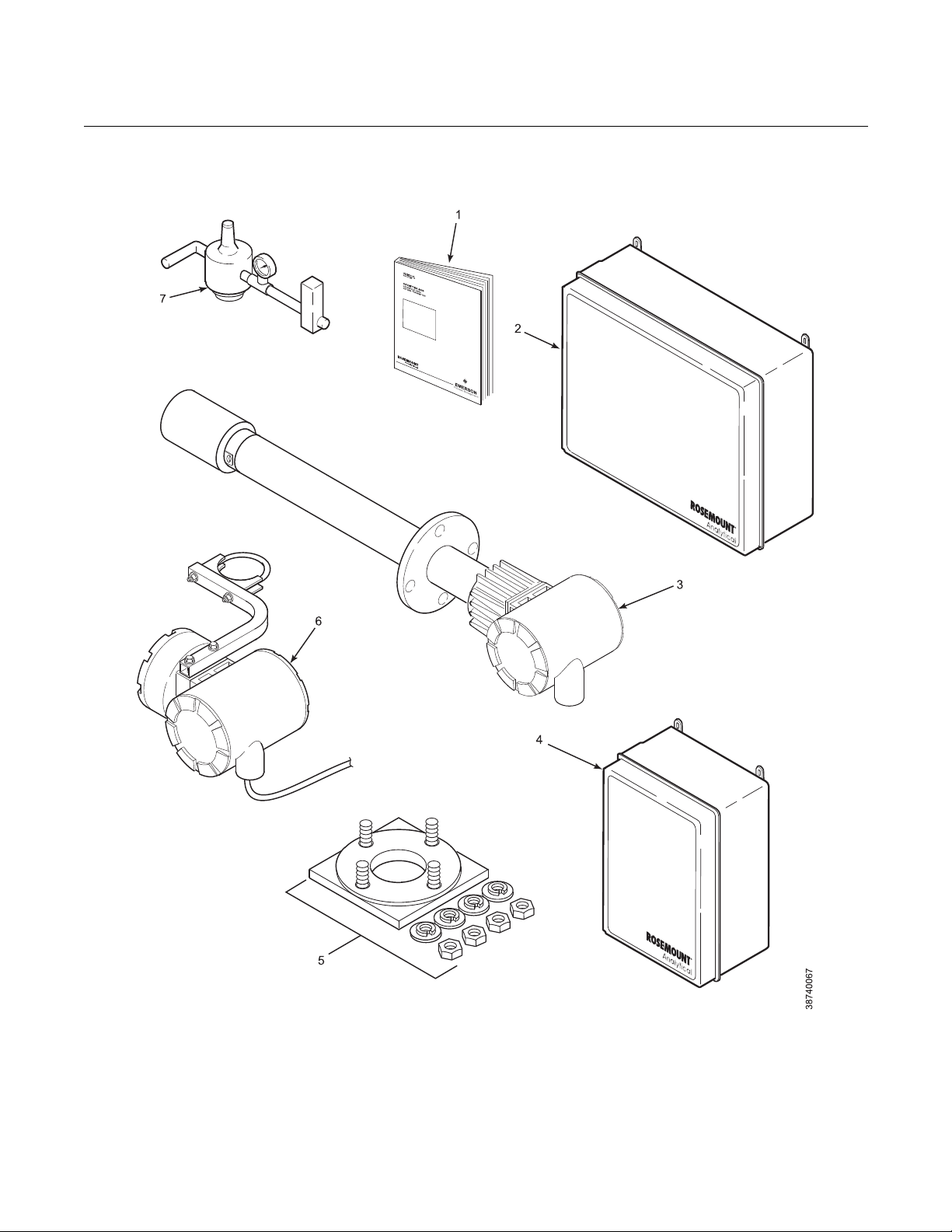
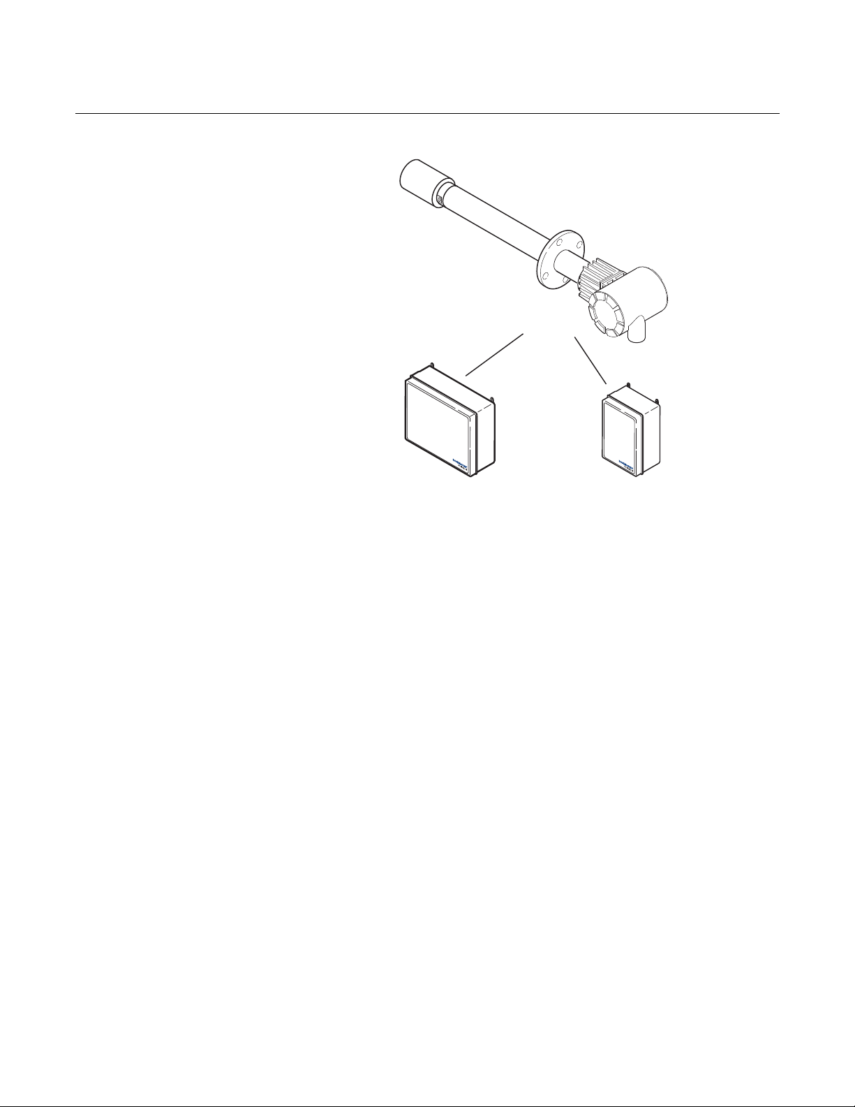
Figure 1-1. Typical System
Package
Instruction Manual
IM-106-350C, Rev 2.2
July 2008
1. Instruction Manual
2. IMPS 4000 Intelligent Multiprobe Test Gas Sequencer (Optional)
3. Hazardous Area Oxymitter 5000 with Integral Electronics
4. SPS 4001B Single Probe Autocalibration Sequencer (Optional) (Safe area only)
5. Mounting Plate with Mounting Hardware and Gasket
6. Hazardous Area Oxymitter 5000 with Remote Electronics (Optional)
7. Reference Air Set (used if SPS 4001B without reference air option or IMPS 4000 not supplied)
1-2
Page 17

Instruction Manual
IM-106-350C, Rev 2.2
July 2008
Hazardous Area Oxymitter 5000
Foundation Fieldbus Technology
System Description
Foundation fieldbus is an all digital, serial, two-way communication system
that interconnects field equipment such as sensors, actuators, and
controllers. Fieldbus is a Local Area Network (LAN) for instruments used in
both process and manufacturing automation with built-in capacity to distribute
the control application across the network. The fieldbus environment is the
base level group of digital networks in the hierarchy of planet networks.
The fieldbus retains the desirable features of the 4-20 mA analog system,
including a standardized physical interface to the wire, bus powered devices
on a single wire, and intrinsic safety options, and enables additional
capabilities, such as:
• Increased capabilities due to full digital communications
• Reduced wiring and wire terminations due to multiple devices on one
set of wires
• Increased selection of suppliers due to interoperability
• Reduced loading on control room equipment with the distribution of
some control and input/output functions to field devices
• Speed options for process control and manufacturing applications
The Hazardous Area Oxymitter 5000 is designed to measure the net
concentration of oxygen in an industrial process; i.e., the oxygen remaining
after all fuels have been oxidized. The probe is permanently positioned within
an exhaust duct or stack and performs its task without the use of a sampling
system.
The equipment measures oxygen percentage by reading the voltage
developed across a heated electrochemical cell, which consists of a small
yttria-stabilized, zirconia disc. Both sides of the disc are coated with porous
metal electrodes. When operated at the proper temperature, the millivolt
output voltage of the cell is given by the following Nernst equation:
EMF = KT log10(P1/P2) + C
Where:
• P2 is the partial pressure of the oxygen in the measured gas on one
side of the cell.
• P1 is the partial pressure of the oxygen in the reference air on the
opposite side of the cell.
• T is the absolute temperature.
• C is the cell constant.
• K is an arithmetic constant.
NOTE
For best results, use clean, dry, instrument air (20.95% oxygen) as the
reference air.
1-3
Page 18

Hazardous Area Oxymitter 5000
When the cell is at operating temperature and there are unequal oxygen
concentrations across the cell, oxygen ions will travel from the high oxygen
partial pressure side to the low oxygen partial pressure side of the cell. The
resulting logarithmic output voltage is approximately 50 mV per decade. The
output is proportional to the inverse logarithm of the oxygen concentration.
Therefore, the output signal increases as the oxygen concentration of the
sample gas decreases. This characteristic enables the Hazardous Area
Oxymitter 5000 to provide exceptional sensitivity at low oxygen
concentrations.
The Hazardous Area Oxymitter 5000 measures net oxygen concentration in
the presence of all the products of combustion, including water vapor.
Therefore, it may be considered an analysis on a "wet" basis. In comparison
with older methods, such as the portable apparatus, which provides an
analysis on a "dry" gas basis, the "wet" analysis will, in general, indicate a
lower percentage of oxygen. The difference will be proportional to the water
content of the sampled gas stream.
Instruction Manual
IM-106-350C, Rev 2.2
July 2008
System Configuration
Hazardous Area Oxymitter 5000 units are available in three length options,
giving the user the flexibility to use an in situ penetration appropriate to the
size of the stack or duct. The options on length are 457 mm (18 in.), 0.91 m (3
ft), and 1.83 m (6 ft).
The electronics control probe temperature and provide an output, that
represents the measured oxygen concentration. The power supply can accept
voltages of 90-250 VAC and 48/62 Hz; therefore, no setup procedures are
required. The oxygen sensing cell is maintained at a constant temperature by
modulating the duty cycle of the probe heater portion of the electronics. The
electronics accepts millivolt signals generated by the sensing cell and
produces the outputs to be used by remotely connected devices. The output
is a FOUNDATION fieldbus digital communication signal.
The Oxymitter 5000 transmitter is available with an integral or remote
electronics package. Two calibration gas sequencers are available to the
Hazardous Area Oxymitter 5000, but they must be installed in a
nonhazardous, explosive-free environment: the IMPS 4000 and the SPS
4001B (Figure 1-2).
Systems with multiprobe applications may employ an optional IMPS 4000
Intelligent Multiprobe Test Gas Sequencer. The IMPS 4000 provides
automatic calibration gas sequencing for up to four Hazardous Area Oxymitter
5000 units and accommodates autocalibrations based on the CALIBRATION
RECOMMENDED signal from the Hazardous Area Oxymitter 5000, a timed
interval set up via fieldbus or the IMPS 4000, or whenever a calibration
request is initiated.
1-4
Page 19
Instruction Manual
HAZARDOUS AREA
OXYMITTER5000
IMPS4000
(1to4Probes)
(Mustbeinstalled
inasafearea
orbeX-orZ-purged
bythecustomer)
SPS4001B
(1Probe)
(Mustbeinstalled
inasafearea)
38740068
IM-106-350C, Rev 2.2
July 2008
Figure 1-2. Hazardous Area
Oxymitter 5000 Autocalibration
System Options
Hazardous Area Oxymitter 5000
System Features
For systems with one or two Hazardous Area Oxymitter 5000 units per
combustion process, an optional SPS 4001B Single Probe Autocalibration
Sequencer can be used with each Hazardous Area Oxymitter 5000 to provide
automatic calibration gas sequencing. The sequencer performs
autocalibrations based on the CALIBRATION RECOMMENDED signal from
the Hazardous Area Oxymitter 5000, a timed interval set up in fieldbus, or
whenever a calibration request is initiated.
1. The CALIBRATION RECOMMENDED feature detects when the sensing
cell is likely out of limits. This may eliminate the need to calibrate on a
"time since last cal" basis.
2. The cell output voltage and sensitivity increase as the oxygen
concentration decreases.
1-5
Page 20
Hazardous Area Oxymitter 5000
DIAGNOSTIC
ALARMS
TEST
POINTS
HEATER T/C
HEATER
02 CELL
CALIBRATION
CALIBRATION RECOMMENDED
02 CELL mV +
02 CELL mv HEATER T/C +
HEATER T/C -
INC INC
DEC DEC
HIGH
GAS
LOW
GAS
CAL
TEST GAS +
PROCESS -
% 02
Membrane
Keypad
38740027
38740028
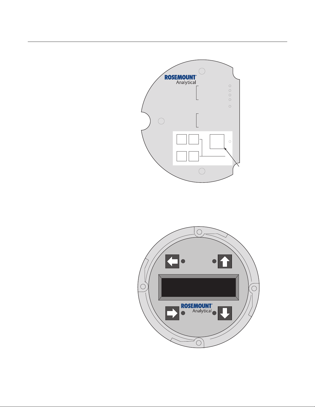
Figure 1-3. Membrane Keypad
Instruction Manual
IM-106-350C, Rev 2.2
July 2008
Figure 1-4. Local Operator
Interface (LOI)
1-6
3. Membrane keypad, Figure 1-3, and FOUNDATION fieldbus
communication are standard.
4. An optional Local Operator Interface Figure 1-4 allows continual O2
display and full interface capability.
5. Field replaceable cell, heater, thermocouple, diffuser, and PC boards.
Page 21

Instruction Manual
IM-106-350C, Rev 2.2
July 2008
Hazardous Area Oxymitter 5000
6. The Hazardous Area Oxymitter 5000 is constructed of rugged 316L
stainless steel for all wetted parts.
7. The electronics are adaptable for line voltages from 90-250 VAC;
therefore, no configuration is necessary.
8. The Hazardous Area Oxymitter 5000 membrane keypad is available in
five languages: English, French, German, Italian, and Spanish.
9. An operator can calibrate and communicate with the Hazardous Area
Oxymitter 5000 in one of four ways:
Accessing the probe keypad requires opening the electronics housing. Opening the
electronics housing will cause the loss of ALL hazardous permits. Opening the electronics
housing in hazardous areas may cause an explosion resulting in loss of property, severe
personal injury, or death. It may be required to get a hot work permit from your company
safety officer before opening the electronic housing.
a. Membrane Keypad. The membrane keypad, housed within the right
side of the electronics housing, provides fault indication by way of
flashing LEDs. Calibration can be performed from the membrane
keypad.
b. Local Operator Interface (LOI). The optional LOI takes the place of
the membrane keypad and allows local communication with the
electronics. Refer to Section 4, Configuration of Hazardous Area
Oxymitter 5000 with LOI for more information.
c. FOUNDATION fieldbus Interface. The Oxymitter 5000's output
carries a signal containing the oxygen level encoded in digital format.
This digital output can also be used to communicate with the
Oxymitter and access all of the Oxymitter’s status information.
d. Optional IMPS 4000. The Programmable Logic Controller (PLC) in
the IMPS 4000 provides fault indications using flashing LEDs and
LCD display messages. Refer to the IMPS 4000 Intelligent
Multiprobe Test Gas Sequencer manual for more information.
Handling the Oxymitter
System Considerations
It is important that printed circuit boards and integrated circuits are handled only when
adequate antistatic precautions have been taken to prevent possible equipment damage.
The Hazardous Area Oxymitter 5000 is designed for industrial applications. Treat each
component of the system with care to avoid physical damage. Some probe components are
made from ceramics, which are susceptible to shock when mishandled.
Prior to installing your Hazardous Area Oxymitter 5000, make sure you have
all the components necessary to make the system installation. Ensure all the
components are properly integrated to make the system functional.
After verifying that you have all the components, select mounting locations
and determine how each component will be placed in terms of available line
voltage, ambient temperatures, environmental considerations, convenience,
and serviceability. Figure 1-5 shows a typical system wiring.
1-7
Page 22
Hazardous Area Oxymitter 5000
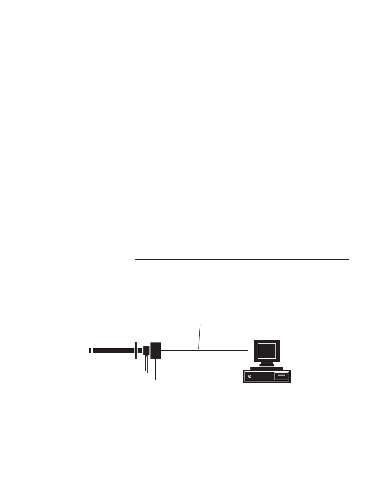
38740001
FieldbusDigital
Signal
2CalibrationGasLines
byCustomer
[90m(300ft)max]
FieldbusComputer
Terminal
LineVoltage
Hazardous Area
Oxymitter5000
withIntegralElectronics
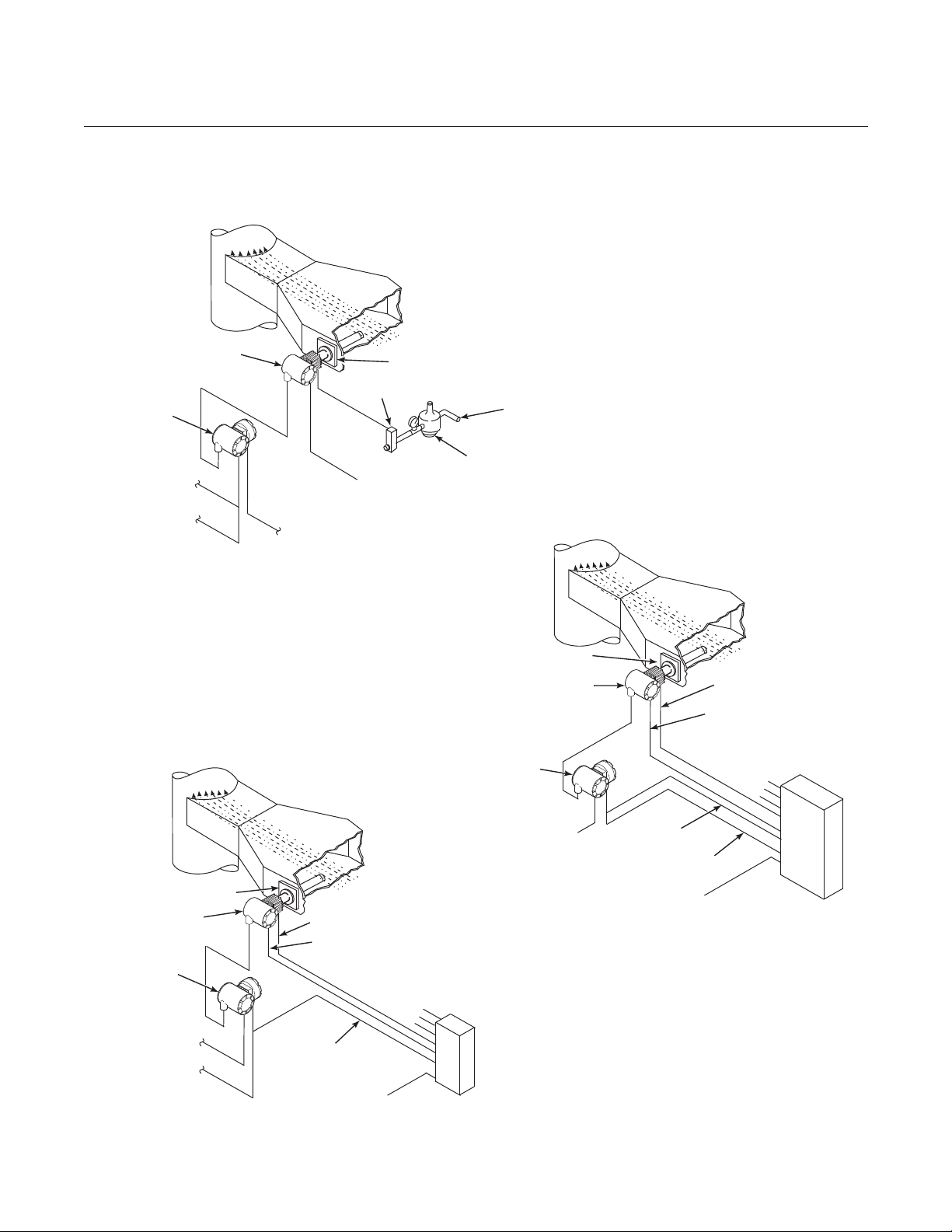
A typical system installation with integral electronics is illustrated in
Figure 1-6. A typical system installation with remote electronics is illustrated in
Figure 1-7.
A source of instrument air is optional at the Hazardous Area Oxymitter 5000
for reference air use. Since the unit can be equipped with an in-place
calibration feature, provisions can be made to permanently connect
calibration gas bottles to the Hazardous Area Oxymitter 5000.
If the calibration gas bottles will be permanently connected, a check valve is
required next to the calibration fittings on the integral electronics.
This check valve is to prevent breathing of the calibration gas line and
subsequent flue gas condensation and corrosion.
The check valve is in addition to the stop valve in the calibration gas kit and
solenoid valves in the IMPS 4000 or SPS 4001B.
NOTE
The integral electronics is rated NEMA 4X (IP66) and is capable of operation
at temperatures up to 85°C (185°F).
Instruction Manual
IM-106-350C, Rev 2.2
July 2008
Figure 1-5. Hazardous Area
Oxymitter 5000 FOUNDATION
Fieldbus Connections
The optional LOI is also rated for operation at temperatures up to 85°C
(185°F). The infrared keypad functionality will deg rade at temperatures above
70°C (158°F).
Retain the original packaging for the Hazardous Area Oxymitter 5000, in case
the components are to be shipped to another site. This packaging is designed
to protect the product.
1-8
Page 23
Instruction Manual
Oxymitter
5000
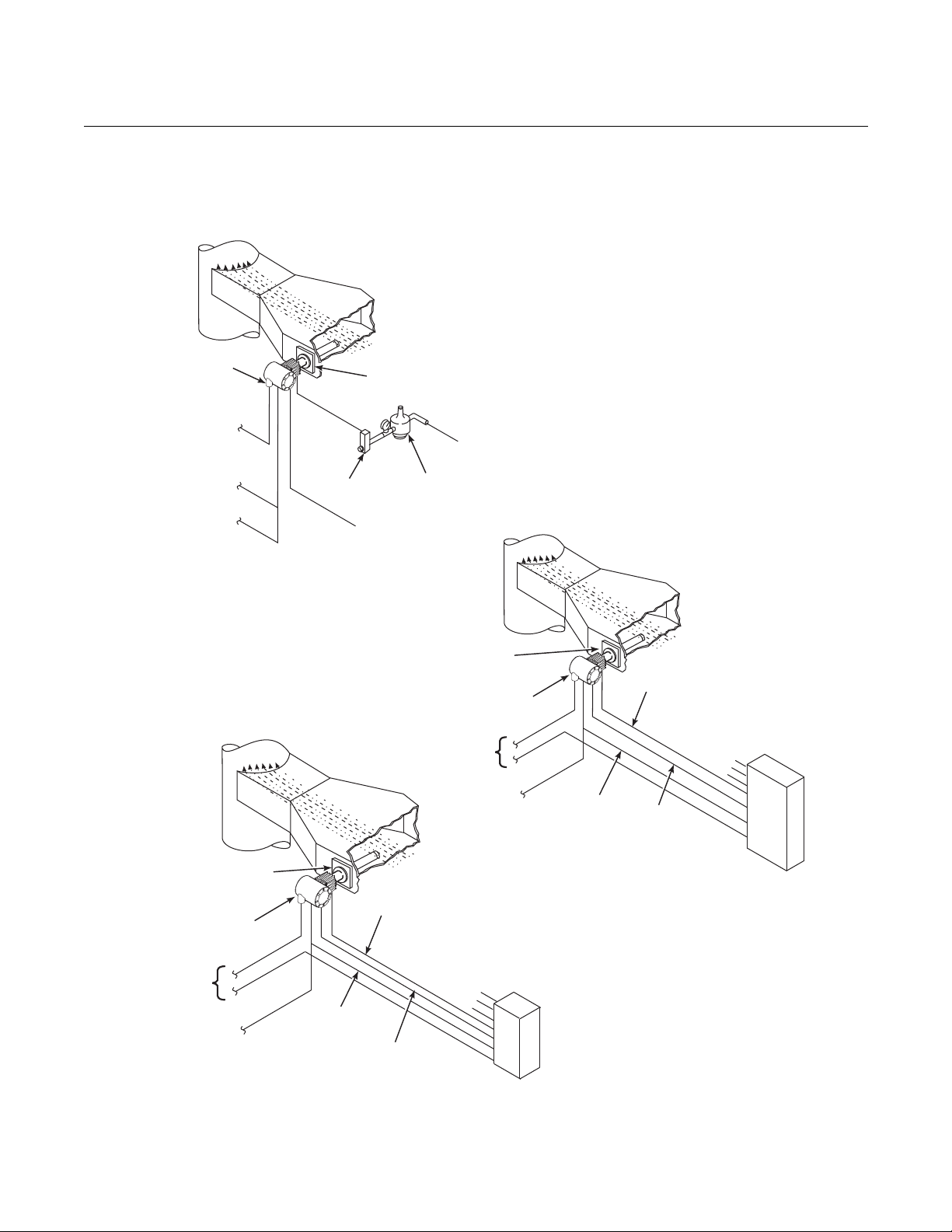
SPS 4001B
Reference
Air
Logic I/O
Calibration Gas
Adapter Plate
Stack
Duct
Gases
Calibration Gas 1
Calibration Gas 2
Inst. Air Supply
Line Voltage
FieldbusDigital
Signal
38740069
Duct
Stack
Gases
Calibration
Gas
Adapter
Plate
Line
Voltage
Logic I/O
Instrument
Air Supply
(Reference Air)
Pressure
Regulator
Flowmeter
STANDARD
Oxymitter
5000
FieldbusDigital
Signal
*Note: The IMPS 4000 or SPS 4001B must
be installed in a non-hazardous,
explosive-free environment.
Oxymitter
5000
IMPS 4000*
MULTIPROBE
AUTOCALIBRATION
OPTION
IMPS 4000
Reference
Air
Logic I/O
Calibration
Gas
Adapter
Plate
Stack
Duct
Gases
Calibration Gas 1
Calibration Gas 2
Inst. Air Supply
Line
Voltage
Fieldbus
DigitalSignal
SPS 4001B* SINGLE PROBE
AUTOCALIBRATION OPTION
(WITH REFERENCE AIR OPTION)
IM-106-350C, Rev 2.2
July 2008
Figure 1-6. Typical System
Installation – Oxymitter 5000
with Integral Electronics
Hazardous Area Oxymitter 5000
1-9
Page 24
Hazardous Area Oxymitter 5000
Duct
Stack
Gases
Calibration
Gas
Adapter Plate
Line
Voltage
Logic I/O
Instrument
Air Supply
(Reference Air)
Pressure
Regulator
Flowmeter
STANDARD
Oxymitter 5000
Oxymitter 5000
FieldbusDigital
Signal
IMPS 4000
Reference Air
Calibration Gas
Adapter Plate
Stack
Duct
Gases
Calibration Gas 1
Calibration Gas 2
Inst. Air Supply
Line Voltage
FieldbusDigitalSignal
Remote
Electronics
Remote
Electronics
Logic I/O
Line Voltage
*Note: TheIMPS4000orSPS4001Bmust
beinstalledinanon-hazardous,
explosive-freeenvironment.
SPS 4001B* SINGLE PROBE
AUTOCALIBRATION OPTION
(WITH REFERENCE AIR OPTION)
Oxymitter
5000
SPS 4001B
Logic I/O
Calibration Gas
Adapter Plate
Stack
Duct
Gases
Calibration Gas 1
Calibration Gas 2
Inst. Air Supply
Remote
Electronics
Line Voltage
Line Voltage
Reference Air
FieldbusDigital
Signal
38740070
IMPS 4000*
MULTIPROBE
AUTOCALIBRATION
OPTION
Figure 1-7. Typical System
Installation – Oxymitter 5000
with Remote Electronics
Instruction Manual
IM-106-350C, Rev 2.2
July 2008
1-10
Page 25

Instruction Manual
IM-106-350C, Rev 2.2
July 2008
Hazardous Area Oxymitter 5000
IMPS 4000 (OPTIONAL)
SPS 4001B (OPTIONAL)
Mounting
If using an IMPS 4000 with a Hazardous Area Oxymitter 5000, the IMPS 4000
sequencer must be installed in a non-hazardous, explosive-free environment.
For further IMPS 4000 information, refer to the IMPS 4000 Intelligent
Multiprobe Test Gas Sequencer Instruction Manual.
If using an SPS 4001B with a Hazardous Area Oxymitter 5000, the SPS
4001B sequencer must be installed in a non-hazardous, explosive-free
environment.
The SPS 4001B is fully enclosed in a NEMA cabinet suited for wall-mounting.
This cabinet provides added protection against dust and minor impacts. The
SPS 4001B consists of a manifold and a calibration gas flowmeter. The manifold provides electrical feedthroughs and calibration gas ports to route power
and signal connections and calibration gases to and from the sequencer. In
addition, the manifold houses two calibration gas solenoids that sequence the
gases to the Oxymitter 5000, a pressure switch that detects low calibration
gas pressure, and two PC boards. A terminal strip housed within the terminal
cover provides convenient access for all user connections.
Components optional to the SPS 4001B include a reference air flowmeter and
pressure regulator. The reference air flowmeter indicates the flow rate of
reference air continuously flowing to the Oxymitter 5000. The reference air
pressure regulator ensures the instrument air (reference air) flowing to the
Oxymitter 5000 is at a constant pressure [20 psi (138 kPa)]. The regulator
also has a filter to remove particulates in the reference air and a drain valve to
bleed the moisture that collects in the filter bowl.
Operation
PROBE OPTIONS
Diffusion Elements
Brass fittings and Teflon tubing are standard. Stainless steel fittings and
tubing are optional. Also, disposable calibration gas bottles are available as
an option or can be purchased through a local supplier.
The SPS 4001B works in conjunction with the Oxymitter 5000's CALIBRATION RECOMMENDED feature to perform an autocalibration. This feature
automatically performs a gasless calibration check every hour on the Oxymitter 5000. If a calibration is recommended and its contact output signal is set
for "handshaking" with the sequencer, the Oxymitter 5000 sends a signal to
the sequencer. The sequencer automatically performs a calibration upon
receiving the signal. Thus, no human interface is required for the automatic
calibration to take place.
For further SPS 4001B information, refer to the SPS 4001B Single Probe
Autocalibration Sequencer Instruction Manual.
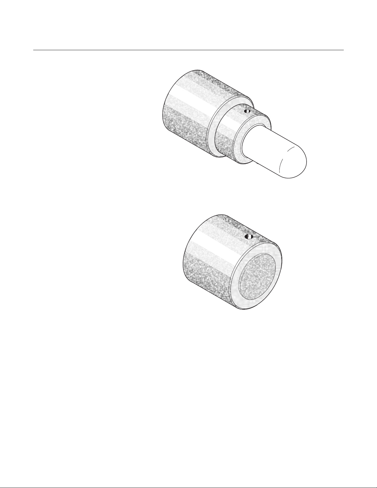
Flame Arrestor Ceramic Diffusion Assembly
The ceramic diffusion assembly, Figure 1-8, includes a set of baffles between
the cell and the stack gases. This keeps 816°C (150 0°F) cell temperatures
from igniting unburned fuel in the stack. The ceramic diffusion assembly is
also available with a dust seal for use with the abrasive shield assembly.
1-11
Page 26
Hazardous Area Oxymitter 5000
38740002
38740003
Instruction Manual
IM-106-350C, Rev 2.2
July 2008
Figure 1-8. Flame Arrestor
Ceramic Diffusion Assembly
Figure 1-9. Flame Arrestor
Snubber Diffusion Assembly
Abrasive Shield Assembly
1-12
Flame Arrestor Snubber Diffusion Assembly
The snubber diffusion assembly, Figure 1-9, is satisfactory for most
applications. This element is also available with a dust seal for use with an
abrasive shield.
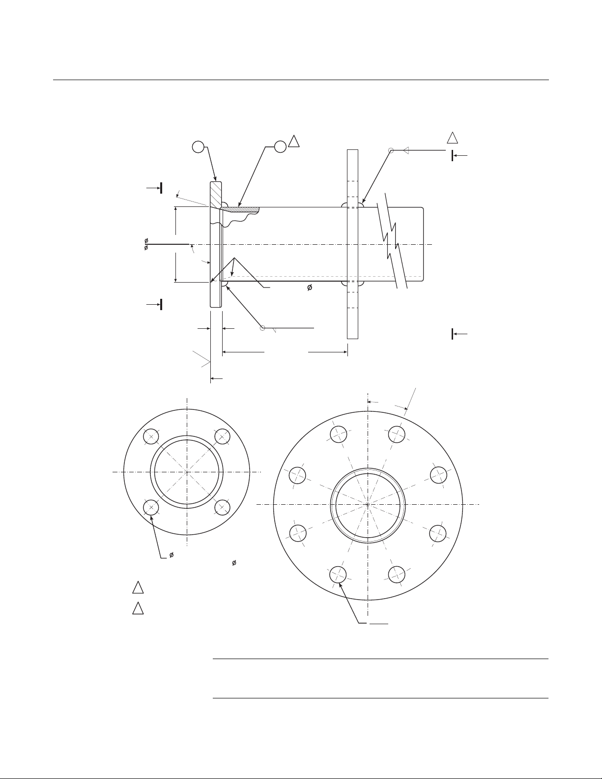
The abrasive shield assembly, Figure 1-10, is a stainless-steel tube that
surrounds the probe assembly. The shield protects against particle abrasion
and condensations, provides a guide for ease of insertion, and acts as a
position support, especially for longer probes. The abrasive shield assembly
uses a modified diffuser and vee deflector assembly, fitted with dual dust seal
packing.
Page 27
Instruction Manual
VIEW A
VIEW B
A
B
A
B
15
o
2
4.7(0.187)
1
Oninsidebreak
forsmooth
roundededgeon
bothendsof
Chamfer.
152.4(6.00)
125
11.4(0.45)MIN
90
o
91.0(3.584)
90.3(3.554)
Skincutfacefor90
o
22.5
o
Diaona190.5(7.50)
DiaB.C.(Ref)
18.9(0.745)
19.2(0.755)
19(0.75)thru4places,
equallyspacedon
120.65(4.75)B.C.
Notes:
1Weldonbothsideswithexpanding
ChillBlock.
2Beforewelding,buttitem2with
item1asshown.
Dimensionsareinmillimeterswith
inchesinparentheses.
38740004
01
02
4.7(0.187)
IM-106-350C, Rev 2.2
July 2008
Figure 1-10. Abrasive Shield
Assembly
Hazardous Area Oxymitter 5000
NOTE
In highly abrasive applications, rotate the shield 90 degrees at normal service
intervals to present a new wear surface to the abrasive flow stream.
1-13
Page 28

Hazardous Area Oxymitter 5000
Fisher-Rosemount has
satisfied all obligations
coming from European
legislation to harmonize
the product requirements
in Europe
SPECIFICATIONS
Hazardous Area Oxymitter Specifications
O2 Range
Standard 0 to 10% O2, 0 to 25% O2, 0 to 40% O2 (via
Accuracy ±0.75% of reading or 0.05% O2, whichever is greater
System Response to Calibration
Gas
Temperature Limits
Process 0° to 704°C (32° to 1300°F) up to 1300°C (2400°F)
Electronics Housing -40° to 70°C (-40° to 158°F) amb ient
Electronics Package -40° to 85°C (-40° to 185°F) [Operating temperature
Local Operator Interface -40° to 70°C (-40° to 158° F), ambient
Probe Lengths 457 mm (18 in.), 0,91 m (3 ft), 1,83 m (6 ft)
Mounting and Mounting Position Vertical or horizontal;
Materials
Probe Wetted or welded parts - 316L stainless steel (SS)
Electronics Enclosure Low-copper aluminum
Calibration Manual, semi-automatic, or automatic
Calibration Gas Mixtures
Recommended
Calibration Gas Flow 2.5 l/min (5 scfh)
Reference Air 0.25 l/min (0.5 scfh), clean, dry, instrument-quality air
Electronics NEMA 4X, IP66 with fitting and pipe on reference
Line Voltage 90-250 VAC, 48/62 Hz; 3/4 in. - 14 NPT conduit port
Pollution Degree 2
Over Voltage Category II
Relative Humidity 5 to 95% (non-condensing)
Foundation fieldbus)
Initial – less than 3 seconds, T90 – less than 8
seconds
with optional accessories
of electronics inside of instrument housing, as
measured by Foundation fieldbus.]
-40° to 85°C (-40° to 185°F), internal [At temperat ures
above 70°C (158°F) inside instrument housing, the
infrared keypad will cease to function, but the
Oxymitter 5000 will continue to operate properly.]
a spool piece, (P/N 3D39761G02), is available to
offset transmitter housing from hot ductwork.
Non-wetted parts - 304 SS, low-copper aluminum
0.4% O2, Balance N
8% O2, Balance N
(20.95% O2), regulated to 34 kPa (5 psi)
exhaust port to clear dry atmosphere
Table continued on next page
2
Instruction Manual
IM-106-350C, Rev 2.2
July 2008
2
1-14
Page 29

Instruction Manual
IM-106-350C, Rev 2.2
July 2008
Hazardous Area Oxymitter 5000
Hazardous Area Oxymitter Specifications
Signals
Digital Output FOUNDATION fieldbus compatible
Logic I/O Two-terminal logic contact configurable as either an
alarm output or as a bi-directional calibration
handshake signal to IMPS 4000 or SPS 4001B,
self-powered (+5 V) in series with 340 ohms
Conduit ports — 3/4 in.-14 NPT (for Foundation
fieldbus and logic I/O signal lines)
Power Requirements:
Probe Heater 175 W nominal
Electronics 10 W nominal
Maximum 500 W
Hazardous Area Oxymitter Certifications
Hazardous Area Oxymitter 5000 with Integral Electronics
KEMA/ATEX II 2 G EEx d IIB+H2 T6 (Elect Comp) / T2 (Probe)
CSA
FM
Hazardous Area Oxymitter with Remote Electronics
KEMA/ATEX
CSA
FM
Class I, Division 1, Groups B, C, D T2
Class I, Zone 1, Ex d IIB+H2 T2
Class I, Zone 1, AEx d IIB+H2 T2
Class I, Division 1, Groups B, C, D T2
Class I, Zone 1, AEx d IIB+H2 T2
II 2 G EEx d IIB+H2 T2 (Remote Probe)
II 2 G EEx de IIB+H2 T6 (Remote Electronics)
Class I, Zone 1, Ex d IIB+H2 T2 (Remote Probe)
Class I, Zone 1, Ex de IIB+H2 T6 (Remote Electronics)
Class I, Zone 1, AEx d IIB+H2 T2 (Remote Probe)
Class I, Zone 1, AEx de IIB+H2 T6 (Remote
Electronics)
Class I, Zone 1, AEx d IIB+H2 T2 (Remote Probe)
Class I, Zone 1, AEx de IIB+H2 T6 (Remote
Electronics)
1-15
Page 30

Hazardous Area Oxymitter 5000
Table 1-1. Product Matrix
OXT5C Oxymitter 5000 Explosion Proof with FOUNDATION fieldbus- In Situ Oxygen Transmitter
Explosion Proof Oxygen Transmitter - Instruction Book
Code Sensing Probe Type with Flame Arrestor
1 Ceramic Diffusion Element Probe (ANSI 3 in. 150 lb bolt cirlce)
2 Snubber Diffusion Element (ANSI 3 in. 150 lb bolt cirlce)
3 Ceramic Diffusion Element Probe (DIN 2527) - 1/4 in. Tube Fittings
4 Snubber Diffusion Element (DIN 2527) - 1/4 in. Tube Fittings
7 Ceramic Diffusion Element Probe (ANSI 3 in. 300 lb bolt cirlce)
8 Ceramic Diffusion Element Probe (ANSI 4 in. 300 lb bolt cirlce)
Code Probe Assembly
0 18 in. (457 mm) Probe
2 18 in. (457 mm) Probe with Abrasive Shield
3 3 ft (0,91 m) Probe
4 3 ft (0,91 m) Probe with Abrasive Shield
5 6 ft (1,83 m) Probe
6 6 ft (1,83 m) Probe with Abrasive Shield
Code Mounting Adaptor- Stack Side
0 No Adaptor Plate ("0" must be chosen under "Mounting Adaptor - Probe Side" below)
1 New Installation - Square weld plate with studs
2 Model 218 Mounting Plate (with Model 218 Shield Removed)
3 Competitor’s Mount
Code Mounting Adaptor-Probe Side
0 No Adaptor Plate
1 Probe Only (ANSI)
2 New Bypass or New Abrasive Shield (ANSI)
4 Probe Only (DIN)
5 New Bypass or New Abrasive Shield (DIN)
Code Electronic Housing - NEMA 4X, IP66
12 FOUNDATION fieldbus electronics, mounted integral to probe, transient
protected termination ATEX EExdllB+H2T2
14 FOUNDATION fieldbus electronics, mounted remotely, transient protected
termination; requires cable ATEX EExdllB+H2T2
22 FOUNDATION fieldbus electronics, mounted integral to probe, transient
protected termination Class I Div. I, Group B,C,D
24 FOUNDATION fieldbus electronics, mounted remotely, transient protected
termination; requires cable Class I Div. I, Group B,C,D
OXT5C 3 3 1 1 14 Example
(1)
(1)
(1)
Instruction Manual
IM-106-350C, Rev 2.2
July 2008
1-16
Page 31

Instruction Manual
IM-106-350C, Rev 2.2
July 2008
Cont’d
Code Operator Interface
1 Membrane Keypad - Fieldbus, Blind Cover
2 Membrane Keypad - Fieldbus, Window Cover
3 Gas Florescent LOI, Fieldbus, English only, Window Cover
Code Language
1 English
2 German
3 French
4 Spanish
5 Italian
Code Termination Filtering
Cont’d 1 3 00 01 00 00 00 Example
(3)
00 No Option - Specified as part of Electronic Housing
Code Calibration Accessories
00 No Hardware
01 Cal/Ref Flowmeters and Reference Pressure Regulator
02 Autocalibration Systems - order by seperate part number (for safe areas only)
Code Hazardous Area Approval
00 certification selected elsewhere
Code Control Suite Functionality
Hazardous Area Oxymitter 5000
00 Basic Control Suite
01 Deduct Basic Control Suite
Code Electronics to Probe Cable
00 No Cable, Integral Electronics
10 20 ft (6 m) Cable - Remote Electronics
11 40 ft (12 m) Cable - Remote Electronics
12 60 ft (18 m) Cable - Remote Electronics
13 80 ft (24 m) Cable - Remote Electronics
14 100 ft (30 m) Cable - Remote Electronics
15 150 ft (45 m) Cable - Remote Electronics
16 200 ft (61 m) Cable - Remote Electronics
NOTES:
High Sulfur Service:
High sulfur cell can be selected for any probe; add a line item note to your purchase order requesing the high sulfur ZrO2 cell in place of the standard ZrO2 cell.
(1)
Recommended uses: High velocity particulates in flue stream, installation within 10ft (3,5 m) of soot blowers or heavy salt cake buildup. Applications:
Pulverized coal, recovery boilers, lime kiln.
(2)
Where possible, specify ANSI or DIN designation; otherwise, provide details of the existing mounting plate as follows:
Plate with studs Bolt circle diameter, number, and arrangement of studs; stud thread; and stud height above mounting plate.
Plate without studs Bolt circle diameter, number, and arrangement of holes; thread; and depth of stud mounting plate with accessories.
(3)
Startup, calibration, and operation can be implemented using the standard membrane keypad. Remote access and additional functionality available via
Fieldbus Communications (DeltaV).
1-17
Page 32

Hazardous Area Oxymitter 5000
Table 1-2. Calibration
Components
Table 1-3. Intelligent Multiprobe
Test Gas Sequencer Versions
Part Number Description
1A99119G01 Two disposable calibration gas bottles - 0.4% and 8% O2, balance
1A99119G02 Two pressure regulators for calibration gas bottles
1A99119G03 Bottle rack
Notes:
*Calibration gas bottles cannot be shipped via airfreight.
When the bottles are used with CALIBRATION RECOMMENDED features, the bottles should provide
2 to 3 years of calibrations in normal service.
Part Number Description Number of Oxymitters
3D39695G01 IMPS 1
3D39695G02 IMPS 2
3D39695G03 IMPS 3
3D39695G04 IMPS 4
3D39695G05 IMPS w/115 V Heater 1
3D39695G06 IMPS w/115 V Heater 2
3D39695G07 IMPS w/115 V Heater 3
3D39695G08 IMPS w/115 V Heater 4
3D39695G09 IMPS w/220V Heater 1
3D39695G10 IMPS w/220V Heater 2
3D39695G11 IMPS w/220V Heater 3
3D39695G12 IMPS w/220V Heater 4
Instruction Manual
IM-106-350C, Rev 2.2
July 2008
nitrogen - 550 liters each*
1-18
Page 33

Instruction Manual
IM-106-350C, Rev 2.2
July 2008
Hazardous Area Oxymitter 5000
Section 2 Installation
Mechanical Installation . . . . . . . . . . . . . . . . . . . . . . . . . . . page 2-2
Electrical Installation with Integral Electronics . . . . . . . .page 2-10
Electrical Installation with Remote Electronics . . . . . . . . page 2-13
Pneumatic Installation . . . . . . . . . . . . . . . . . . . . . . . . . . . .page 2-17
IMPS 4000 Connections . . . . . . . . . . . . . . . . . . . . . . . . . . . page 2-18
SPS 4001B Connections . . . . . . . . . . . . . . . . . . . . . . . . . .page 2-18
Before installing this equipment, read the "Safety Instructions" for the wiring and installation
of this apparatus in Appendix A of this Instruction Manual. Failure to follow safety
instructions could result in serious injury or death.
The Hazardous Area Oxymitter 5000 and probe abrasive shield are heavy. Use proper
lifting and carrying procedures to avoid personal injury.
Install all protective equipment covers and safety ground leads after installation. Failure to
install covers and ground leads could result in serious injury or death.
http://www.raihome.com
Page 34

Hazardous Area Oxymitter 5000
MECHANICAL INSTALLATION
Instruction Manual
IM-106-350C, Rev 2.2
July 2008
Selecting Location
1. The location of the Hazardous Area Oxymitter 5000 in the stack or flue
is most important for maximum accuracy in the oxygen analyzing
process. The Hazardous Area Oxymitter 5000 must be positioned so
the gas it measures is representative of the process. Best results are
normally obtained if the Hazardous Area Oxymitter 5000 is positioned
near the center of the duct (40 to 60% insertion). Longer ducts may
require several Hazardous Area Oxymitter 5000 units since the O2 can
vary due to stratification. A point too near the wall of the duct, or the
inside radius of a bend, may not provide a representative sample
because of the very low flow conditions. The sensing point should be
selected so the process gas temperature falls within a range of 0° to
704°C (32° to 1300°F). Figure 2-1 through Figure 2-5 provide
mechanical installation references.
The ambient temperature of the electronics housing must not exceed
70°C (150°F). For higher ambient temperatures, we r ecommend the
remote mounted electronics option.
NOTE
At temperatures up to 85°C (185°F) inside the housi ng, the infrared keypad
will cease to function, but the transmitter will continue to operate properly.
2. Check the flue or stack for holes and air leakage. The presence of this
condition will substantially affect the accuracy of the oxygen reading.
Therefore, either make the necessary repairs or install the Hazardous
Area Oxymitter 5000 upstream of any leakage.
3. Ensure the area is clear of internal and external obstructions that will
interfere with probe installation and access to the membrane keypad or
LOI. Allow adequate clearance for removal of the Hazardous Area
Oxymitter 5000 (Figure 2-1 or Figure 2-3).
Probe Installation
2-2
Do not allow the temperature of the Hazardous Area Oxymitter 5000 electronics to exceed
85°C (185°F) or damage to the unit may result.
1. Ensure all components are available to install the Hazardous Area
Oxymitter 5000. If equipped with a ceramic diffuser, make sure the
diffuser is not damaged.
2. The Hazardous Area Oxymitter 5000 probe may be installed intact, as it
is received.
NOTE
An abrasive shield is recommended for high velocity particulates in the flu
stream (such as those in coal-fired boilers, kilns, and recovery boilers).
3. Weld or bolt mounting plate (Figure 2-5) onto the duct.
Page 35

Instruction Manual
CoverRemoval& Access
305
305
(12)
(12)
AddtoDIM“A”
forProbewith
CeramicDiffuser
95(3.8)
with
Snubber
Diffuser
DIM"A"
66
(2.6)
76
(3.0)
DIM"B”
RemovalEnvelope
ElecConn
3/4NPT
ANSI ( ) Tube6.35 1/4
DIN
6.35(1/4) Tube
CAL Gas
Ref Air
BottomView
P
S
U
E
I
T
P
I
C
R
H
W
E
N
T
H
G
C
K
E
N
I
-
E
E
R
W
A
V
I
S
O
L
P
-
X
O
M
T
A
G
N
I
N
-
R
I
T
L
A
I
V
E
-
E
E
H
343(13.5)
CAL.
GAS
REF.
GAS
-
-
R
H
G
T
I
N
E
W
H
C
I
T
K
E
P
E
A
I
T
C
U
E
V
L
I
-
M
N
I
N
L
O
A
R
P
N
I
X
E
-
W
G
E
S
I
V
A
T
O
S
E
H
E
R
P
167
(6.58)
(2.89)
73
(1.55)
39
Theseflatfacedflangesare
manufacturedto ANSIandDIN
patterns,andarenotpressurerated.
Alldimensionsareinmillimeters
withinchesinparenthesesunless
otherwisenoted.
Notes:
0.062in.thickGasket
Certification
Approved
Label
External
Earth
External
Earth
Vent
Ref. Air
Internal
Earth
Table1.MountingFlange
(gasketincluded)
(4)Holes
EqSp
onBC
HoleDia
Flange
Dia
DIN
ANSI
152.4
(6.00)
190
(7.5)
19(0.75)
170
(6.69)
18(0.71)
210
(8.25)
Table2.Installation/Removal
DIM"A"
3ft
6ft
Probe
18in.
DIM"B"
2174
(85.6)
1831
(72.1)
917
(36.1)
1448
(57.0)
803
(31.6)
460
(18.1)
38740071
Insulateifexposedto
ambientweatherconditions
Processflowmustbein
thisdirectionwithrespect
toDeflector3534B48G01
500VA
SERIALNO.
TAGNO.
OXYMITTER5000
WATTS:
VOLTS:
FUSE:LINE
OUTPUT:
RosemountAnalyticalInc.
Solon,OH44139
85-264VAC48-62Hz
TM
800-433-6076
4-20 mA
R
5Amps
TM
HART
SMARTFAMILY
IM-106-350C, Rev 2.2
July 2008
Figure 2-1. Hazardous Area
Oxymitter 5000 Probe
Installation
Hazardous Area Oxymitter 5000
2-3
Page 36

Hazardous Area Oxymitter 5000
( )
56.0
2.21
( )
164.6
6.48
246.9 9.72( )
84.6
3.33( )
62.0
(2.44)
DIA.
189.8
7.47( )
140.2
5.52( )
66.5
2.62( )
93.5(3.68)
PipeMount
Configuration
REMOTEELECTRONICS
WITHLOI ANDWINDOWCOVER
REMOTEELECTRONICS
WITHMEMBRANEKEYPAD ANDBLINDCOVER
38740029
WallMount
Configuration
Note: Alldimensionsarein
millimeterswithinchesin
parentheses.
Figure 2-2. Hazardous Area
Oxymitter 5000 Remote
Electronics Installation
Instruction Manual
IM-106-350C, Rev 2.2
July 2008
2-4
Page 37

Instruction Manual
P
S
U
E
I
T
P
I
C
R
H
W
E
N
T
H
G
C
K
E
N
I
-
E
E
R
W
A
V
I
S
O
L
P
-
X
O
M
T
A
G
N
I
N
-
R
I
T
L
A
I
V
E
-
E
E
H
Deflector Assy
3ft
18in.
Probe
Table3. Installation/Removal
6ft
(33.2)
843
(69.4)
1762
387
(15.3)
DIM"A”
1367
(53.8)
2287
(90.0)
912
(35.9)
DIM"B”
Diffuser/Dust
Seal Assy
*AddCheckValveinCAL GasLine
3/4NPT ElectricalConnection
Ref Air
CAL Gas*
ANSI
DIN
1/4in. Tube
1/4in. Tube
GAS
CAL.
Snubber/DustSeal
Assembly
5
(0.2)
91(3.6)Dia
Nominal
99
(3.9)
DIM"A"
Notes:
RemovalEnvelope
DIM"B”
178
(7.00)
343
(13.50)
38740072
(8)Holes
EqSp
OnBC
3D39003
Table4. AbrasiveShield
Hole
Dia
Flange
Dia
229
(9.00)
235
(9.25)
19
(0.75)
24
(0.94)
190
(7.50)
190
(7.48)
Flange
ANSI
DIN
Theseflatfacedflangesaremanufacturedto ANSIandDIN
patterns,andarenotpressurerated.
Alldimensionsareinmillimeterswithinchesinparentheses.
IM-106-350C, Rev 2.2
July 2008
Figure 2-3. Hazardous Area
Oxymitter 5000 Probe with
Abrasive Shield
Hazardous Area Oxymitter 5000
2-5
Page 38

Hazardous Area Oxymitter 5000
22.5
o
B
C
8 Threadedholes
equallyspaced
onDDiaB.C.
AbrasiveShield
FlangeO.D.
A
A
Table5.MountingPlateDimensionsfor
Hazardous AreaOxymitter5000
Dimensions
mm
(in.)
"A"
"B”
StudSize
“C"
DiaB.C.
ANSI
197
(7.75)
0.625-11
152.4
(6.00)
DIN
216
(8.50)
M16x2
170.0
(6.69)
MOUNTINGPLATEFOR
HAZARDOUS AREA OXYMITTER5000
WITH ABRASIVESHIELD
MOUNTINGPLATEFOR
HAZARDOUS AREA OXYMITTER5000
Crosshatchedareain
4cornersmaybeused
toprovideadditional
holesforfieldbolting
ofplatetooutside
wallsurface.
4Studs,
Lockwashersand
Nutsequally
spacedonCDia
B.C.
A
82.6
(3.25)Dia
B
38740073
C
MOUNTINGPLATEOUTLINE
Note:Dimensionsareinmillimeters
withinchesinparentheses.
Table6.MountingPlateDimensionsforHazardous Area
Oxymitter5000with AbrasiveShield
DIN
235
(9.25)
100
(3.94)
190
(7.48)
M20x2.5
ANSI
229
(9.00)
121
(4.75)
191
(7.50)
0.625-11
Dimensions
mm
(in.)
"A"
"B"
Dia
"D"
DiaB.C.
"C"
Thread
Figure 2-4. Hazardous Area
Oxymitter 5000 Mounting Plate
Dimensions
Instruction Manual
IM-106-350C, Rev 2.2
July 2008
2-6
Page 39

Instruction Manual
13(0.50)
95(3.75)
MinimumDia
HoleinWall
StackorDuct
MetalWall
Mountingholes
shownrotated45
o
Weldorboltmountingplatetometalwall
ofstackorduct;Jointmustbeairtight.
13 0.50( )
114(4.50)
O.D.Ref
Pipe4.00in.Sched40Pipe
Sleeve(NotbyEmerson
ProcessManagement)
lengthbyCustomer
Masonry
stackwall
OutsideWall
Surface
JointMust
be Air Tight
MountingHoles
ShownRotated45
of TruePosition
o
FieldWeldPipe
toMountingPlate
BoltMountingPlateto
OutsideWallSurface
82.5(3.25)
MinimumDia
HoleinWall
StackorDuct
MetalWall
Weldorboltmountingplateto
metalwallofstackorduct.
Jointmustbeairtight.
Fieldweldpipe
toMountingPlate
102(4.0)
O.D.Ref
Pipe3.5in.Sched40Pipe
Sleeve(Notby
)
lengthbyCustomer
Emerson
ProcessManagement
Masonry
stackwall
OutsideWall
Surface
JointMust
be Air Tight
BoltMountingPlateto
OutsideWallSurface
38740005
INSTALLATIONFORMASONRY
WALL STACKCONSTRUCTION
INSTALLATIONFORMETAL WALL
STACKORDUCTCONSTRUCTION
Notes:
1.Dimensionsareinmillimeterswith
inchesinparentheses.
ABRASIVESHIELDMOUNTING
PROBEMOUNTING
outoftrueposition
out
2. Allmasonrystackworkandjointsexceptadaptor
platearenotfurnishedbyRosemont Analytical.
IM-106-350C, Rev 2.2
July 2008
Figure 2-5. Hazardous Area
Oxymitter 5000 Mounting Plate
Installation
Hazardous Area Oxymitter 5000
2-7
Page 40

Hazardous Area Oxymitter 5000
4. If using the optional ceramic diffusion element, the vee deflector must
be correctly oriented. Before inserting the Hazardous Area Oxymitter
5000, check the direction of flow of the gas in the duct. Orient the vee
deflector so the apex points upstream toward the flow (Figure 2-6). This
may be done by loosening the setscrews and rotating the vee deflector
to the desired position. Retighten the setscrews.
5. In vertical installations, ensure the system cable drops vertically from
the Hazardous Area Oxymitter 5000 and the conduit is routed below the
level of the electronics housing. This drip loop minimizes the possibility
that moisture will damage the electronics (Figure 2-7).
6. If the system has an abrasive shield, check the dust seal gaskets. The
joints in the two gaskets must be staggered 180 degrees. Make sure the
gaskets are in the hub grooves as the Hazardous Area Oxymitter 5000
slides into the 15 degree forcing cone in the abrasive shield.
NOTE
If process temperatures will exceed 200°C (392°F), use anti-seize compound
on the stud threads to ease future removal of the Hazardous Area Oxymitter
5000.
Instruction Manual
IM-106-350C, Rev 2.2
July 2008
7. Insert probe through the opening in the mounting plate and bolt the unit
to the plate.
NOTE
To maintain CE compliance, ensure a good connection exists between the
mounting plate studs or earthing screws on electronics housing and earth.
8. Ensure the Hazardous Area Oxymitter 5000 is properly earthed by way
of both internal and external points.
Uninsulated stacks or ducts may cause ambient temperatures around the electronics to
exceed 85°C (185°F), which may cause overheating da mage to the electronics
.
9. If duct work insulation is removed for Hazardous Area Oxymitter 5000
probe mounting, make sure the insulation is replaced afterward. See
Figure 2-7.
NOTE
For probe temperatures that will exceed 85°C (185°F ), we recommend the
remote mounted electronics option.
2-8
10. Ensure the probe installation does not obscure the warnings on the
housing covers.
Page 41

Instruction Manual
Vee
Deflector
Vee
Deflector
Ceramic
Diffusion
Element
Setscrew
Filter
GasFlow
Direction
38740006
Apex
P
S
U
E
I
T
P
I
C
R
H
W
E
N
T
H
G
C
K
E
N
I
-
E
E
R
W
A
V
I
S
O
L
P
-
X
O
M
T
A
G
N
I
N
-
R
I
T
L
A
I
V
E
-
E
E
H
GAS
CAL.
LineVotage
FieldbusDigital
Signal
StackorDuct
MetalWall
MountingPlate
ReplaceInsulationafter
InstallingHazardous
AreaOxymitter5000
Insulation
38740007
Drip
Loop
IM-106-350C, Rev 2.2
July 2008
Figure 2-6. Orienting the
Optional Vee Deflector
Hazardous Area Oxymitter 5000
Figure 2-7. Installation with Drip
Loop and Insulation Removal
2-9
Page 42

Hazardous Area Oxymitter 5000
38740008
Instruction Manual
IM-106-350C, Rev 2.2
July 2008
Remote Electronics Installation
Figure 2-8. Remote Electronics
Mounting
ELECTRICAL INSTALLATION WITH INTEGRAL ELECTRONICS
For a Hazardous Area Oxymitter 5000 with the remote electronics option,
install the probe according to the instructions in “Probe Installation” on
page 2-2. Install the remote electronics unit on a wall, stand pipe, or similar
structure (Figure 2-2 and Figure 2-8).
All wiring must conform to local and national codes.
Disconnect and lock out power before connecting the unit to the power supply.
Install all protective equipment covers and safety ground leads after installation. Failure to
install covers and ground leads could result in serious injury or death.
To meet the Safety Requirements of IEC 1010 (EC requirement), and ensure safe operation
of this equipment, connection to the main electrical power supply must be made through a
circuit breaker (min 10 A) which will disconnect all current-carrying conductors during a fault
situation. This circuit breaker should also include a mechanically operated isolating switch.
If not, then another external means of disconnecting the supply from the equipment should
be located close by. Circuit breakers or switches must comply with a recognized standard
such as IEC 947.
The probe and probe abrasive shield are heavy. Use proper lifting and carrying procedures
to avoid personnel injury.
2-10
Page 43

Instruction Manual
IM-106-350C, Rev 2.2
July 2008
Hazardous Area Oxymitter 5000
To maintain explosion-proof protection, all cable entry devices and blanking elements for
unused apertures must be certified flameproof, suitable for the conditions of use and be
properly installed.
NOTE
To maintain CE compliance, ensure a good connection exists between the
mounting flange bolts and earth.
Connect Line Voltage
1. Remove screw (18, Figure 9-3), cover lock (19), and captive washer
(20). Remove cover (17) from terminal block (15).
2. Connect the line, or L1, wire to the L1 terminal and the neutral, or L2
wire, to the N terminal. See Figure 2-9. The Hazardous Area Oxymitter
5000 automatically will configure itself for 90-250 VAC line voltage and
50/60 Hz. To avoid a shock hazard, the power terminal cover must be
installed.
3. Connect fieldbus Digital Signal and Logic I/O Calibration Handshake
Leads. Use individual shielded twisted wire pairs. Terminate the shield
only at the electronics housing.
a. Fieldbus Digital Signal. The fieldbus digital signal carries the O2
value. This digital signal can also be used to communicate with the
Oxymitter.
If using an IMPS 4000 or an SPS 4001B, install it in a non-hazardous, explosive-free
environment.
b. Calibration Handshake/Logic I/O. The output signal can be used to
trigger an alarm or to provide a calibration handshake signal to an
IMPS or SPS 4001B.
c. If autocalibration is not utilized, a common bi-directional logic contact
is provided for any of the equipment alarms listed in Table 8-1. The
assignment of alarms that will actuate this contact is modified by one
of seven additional configuration settings (mode 1 through mode 7)
listed in Table 4-1.
The logic contact is self-powered, +5 VDC, with a 340 ohm series
resistance. An interposing relay is required if the logic contact will
annunciate a higher voltage device, such as a light or horn. An
interposing relay may also be required for certain DCS input cards. A
Potter & Brumfield model R10S-E1Y1-J1.0K 3.2 mA DC (or equal)
interposing relay will be mounted where the contact wires terminate
in the control/relay room.
4. Install cover (17, Figure 9-3) and secure with captive washer (20), cover
lock (19), and screw (18).
2-11
Page 44

Hazardous Area Oxymitter 5000
38740074
INTEGRAL ELECTRONICS
WITHOUTSPS4001B
AC L1
AC N
+
+
-
-
LogicI/O+
LogicI/O–
Ground
Line1
Neutral
Ground
90-250VAC,50-60Hz
LineVoltageInput
CalibrationHandshake
RefertoIMPS4000
InstructionManual
INTEGRAL ELECTRONICS
WITHREMOTESPS4001B
INTEGRAL ELECTRONICS
WITHREMOTEIMPS4000
Line1
Neutral
Ground
90-250VAC,50-60Hz
LineVoltageInput
Calibration
Handshake
LineVoltage
Calibration
Handshake/
LogicI/O
Terminal
Block
Ground
Lugs
Line1
Neutral
Ground
+
–
Ground
90-250VAC,50-60Hz
LineVoltageInput
90-250VAC,50-60Hz
LineVoltageInput
Line1
Neutral
Ground
Ground
FieldbusDigitalSignal
+
–
+
–
FieldbusDigitalSignal
FieldbusDigitalSignal
FieldbusDigitalSignal
FieldbusDigitalSignal
FieldbusDigitalSignal
FieldbusDigitalSignal
WALL-MOUNTED
SPS4001B
Calibration
Handshake
Figure 2-9. Electrical Installation Hazardous Area Oxymitter
5000 with Integral Electronics
Instruction Manual
IM-106-350C, Rev 2.2
July 2008
2-12
Page 45

Instruction Manual
IM-106-350C, Rev 2.2
July 2008
Hazardous Area Oxymitter 5000
ELECTRICAL INSTALLATION WITH REMOTE ELECTRONICS
All wiring must conform to local and national codes.
Disconnect and lock out power before connecting the unit to the power supply.
Install all protective equipment covers and safety ground leads after installation. Failure to
install covers and ground leads could result in serious injury or death.
To meet the Safety Requirements of IEC 1010 (EC requirement), and ensure safe operation
of this equipment, connection to the main electrical power supply must be made through a
circuit breaker (min 10 A) which will disconnect all current-carrying conductors during a fault
situation. This circuit breaker should also include a mechanically operated isolating switch.
If not, then another external means of disconnecting the supply from the equipment should
be located close by. Circuit breakers or switches must comply with a recognized standard
such as IEC 947.
The probe and probe abrasive shield are heavy. Use proper lifting and carrying procedures
to avoid personnel injury.
To maintain explosion-proof protection, all cable entry devices and blanking elements for
unused apertures must be certified flameproof, suitable for the conditions of use and be
properly installed.
NOTE
To maintain CE compliance, ensure a good connection exists between the
mounting flange bolts and earth.
2-13
Page 46

Hazardous Area Oxymitter 5000
Instruction Manual
IM-106-350C, Rev 2.2
July 2008
Connect Line Voltage
Calibration Handshake Logic I/O
1. Remove screw (18, Figure 9-4), cover lock (19), captive washer (20),
and left side blind cover (17) from the remote electronics.
2. Connect the line, or L1, wire to the L1 terminal and the neutral, or L2
wire, to the N terminal (Figure 2-10). The Hazardous Area Oxymitter
5000 will automatically configure itself for 90-250 VAC line voltage and
50/60 Hz. To avoid a shock hazard, the power terminal cover must be
installed.
3. Connect fieldbus Digital Signal and Logic I/O Calibration Handshake
Leads (Figure 2-10). Use individual shielded twisted wire pairs.
Terminate the shield only at the electronics housing.
a. Fieldbus Digital Signal. The fieldbus digital signal carries the O2
value. This digital signal can also be used to communicate with the
Oxymitter.
If using an IMPS 4000 or an SPS 4001B, install it in a non-hazardous, explosive-free
environment.
1. The output signal can be used to trigger an alarm or to provide a
calibration handshake signal to an IMPS or SPS 4001B.
a. If autocalibration is not utilized, a common bi-directional logic contact
is provided for any of the equipment alarms listed in Table 8-1. The
assignment of alarms that will actuate this contact is modified by one
of seven additional configuration settings (mode 1 through mode 7)
listed in Table 4-1.
b. The logic contact is self-powered, +5 VDC, with a 340 ohm series
resistance. An interposing relay is required if the logic contact will
annunciate a higher voltage device, such as a light or horn. An
interposing relay may also be required for certain DCS input cards. A
Potter & Brumfield model R10S-E1Y1-J1.0K 3.2 mA DC (or equal)
interposing relay will be mounted where the contact wires terminate
in the control/relay room.
2. Install cover (17, Figure 9-4) and secure with captive washer (20), cover
lock (19), and screw (18).
2-14
Page 47

Instruction Manual
OxygenSignal
+
+
-
-
38740009
ACL1
ACN
+
+
-
-
1 2
3
4
GRN
ORN
YEL
RED
BLK
BLK
ORN
RED
BLK
HTR
T/C
O
CELL
2
WIRINGDIAGRAM
TOELECTRONICS
FROMPROBE
WHT
BRN
GRN
RED
BRN
BLU
PROBE
REMOTE
ELECTRONICS
5 6
7
8
(WHT)
(RED)
(BLU)
(HAZ.)
(BRN)
(GRN)
(BRN)
BLU
YEL
WHT
GRN/YEL
orGRN
G.P.
TypeK
Thermocouple
Signal
Terminal
Block
Ground
Lugs
HeaterPower
(BelowCover)
Calibration
Handshake/
LogicI/O
LineVoltage
FieldbusDigital
Signal
Terminal
Block
GroundLugs
Interconnecting
Cable
ToIMPS4000ifused.
RefertoIMPS4000
InstructionManual.
LogicI/O+
LogicI/O
+
Line1
Neutral
Ground
90-250VAC,50-60Hz
LineVoltageInput
FieldbusDigitalSignal
Ground
Note: Interconnectingcableis
wiredtotheprobeatthe
factory. Terminal
connectionsshownfor
referenceonly.
GeneralPurpose
Oxymitter
Hazardous Area
Oxymitter
FieldbusDigitalSignal
IM-106-350C, Rev 2.2
July 2008
Figure 2-10. Electrical
Installation - Hazardous Area
Oxymitter 5000 with Remote
Electronics
Hazardous Area Oxymitter 5000
2-15
Page 48

Hazardous Area Oxymitter 5000
Instruction Manual
IM-106-350C, Rev 2.2
July 2008
Install Interconnecting Cable
NOTE
If interconnect cable was not purchased with the Hazardous Area Oxymitter
5000, consult the factory for the proper wire type and gauge.
1. Remove cover (17, Figure 9-4) from the junction box (24). Connect the
electronics end of the interconnecting cable (30) to the "FROM PROBE"
side of the terminal block (Figure 2-10).
If using an IMPS 4000 or an SPS 4001B, install it in a non-hazardous, explosive-free
environment.
2. Loosen screw (18, Figure 9-3), cover lock (19) and washer (20) at the
probe head. Remove cover (17).
3. See (Figure 2-10). Connect the heater power leads, the thermocouple
leads, and the oxygen signal leads of the interconnecting cable to the
terminal block. The cable leads are tagged for polarity. To avoid a shock
hazard, the heater power terminal cover must be installed.
4. Install covers (17, Figure 9-3 and Figure 9-4) and secure with captive
washers (20), cover locks (19), and screws (18).
2-16
Page 49

Instruction Manual
38740030
Ref AirSet
263C152G01
1Flowmeter0.006-0.057scmh(0.2-2.0scfh) 771B635H02
2PressureGage0-103kPaGage(0-15psig) 275431-006
3CombinationFilter-Reg.0-207kPaGage(0-30psig) 4505C21G01
Note:Dimensionsareinmillimeters
withinchesinparentheses. All
pipingspecifiedinU.S.Standards.
1
2
3
122.17(4.81)
FlowSet
PointKnob
0.125-27NPT
Outlet
30.22
(1.19)
254
(10.0)
Drain
Valve
79.25( Max3.12)
215.90
(8.50)
Max
50.80
(2.0)
Mounting
Holes
81.03
( )Lg
for
7.92( )
Dia.
Through
Bolts
3.19
0.312
38.10
(1.50)
57.15(2.250)
SCHEMATICHOOKUP FORREFERENCE
AIRSUPPLY TOHAZARDOUS AREA
OXYMITTER5000PROBEHEAD
Outlet
0.25-18
NPT
Inlet
Instrument Air
69-1551kPaGage
(10-225psig)Max.
0.250in.or6mmO.D. Tubing
(SuppliedbyCustomer)
500VA
SERIALNO.
TAGNO.
OXYMITTER5000
WATTS:VOLTS:
FUSE:LINEOUTPUT:
RosemountAnalyticalInc.
Solon,OH44139
85-264VAC48-62Hz
TM
800-433-6076
4-20 mA
R
5Amps
TM
HART
SMARTFAMILY
Ref
2
3
1
ReplacementParts
IM-106-350C, Rev 2.2
July 2008
Hazardous Area Oxymitter 5000
PNEUMATIC INSTALLATION
Figure 2-11. Air Set, Plant Air
Connection
Reference Air Package
After the Hazardous Area Oxymitter 5000 is installed, connect the reference
air set to the Hazardous Area Oxymitter 5000. Refer to Figure 2-11.
Instrument Air (Reference Air): 68.95 kPa gage (10 psig) minimum, 1551.38
kPa gage (225 psig) maximum at 0.25 l/min (0.5 scfh) maximum; less than 40
parts per million total hydrocarbons. Regulator outlet pressure should be set
at 35 kPa (5 psi).
2-17
Page 50

Hazardous Area Oxymitter 5000
500VA
SERIALNO.
TAGNO.
OXYMITTER5000
VOLTS: WATTS:
OUTPUT: LINE FUSE:
85-264VAC48-62Hz
TM
800-433-6076
4-20mA
R
5Amps
TM
HART
SMART FAMILY
CalibrationGas
Reference Air
38740031
Figure 2-12. Hazardous Area
Oxymitter 5000 Gas
Connections
Calibration Gas
Do not use 100% nitrogen as a low gas (zero gas). It is suggested that gas for the low (zero)
be between 0.4% and 2.0% O2. Do not use gases with hydrocarbon concentrations of more
than 40 parts per million. Failure to use proper gases will result in erroneous readings.
Instruction Manual
IM-106-350C, Rev 2.2
July 2008
IMPS 4000 CONNECTIONS
SPS 4001B CONNECTIONS
Two calibration gas concentrations are used with the Hazardous Area
Oxymitter 5000, Low Gas - 0.4% O2 and High Gas - 8% O2. See Figure 2-12
for the Hazardous Area Oxymitter 5000 connections.
If using an IMPS 4000 or an SPS 4001B, install it in a non-hazardous, explosive-free
environment.
Ensure the IMPS 4000 is installed in a safe (non-hazardous, explosive-free)
area and verify the wiring and pneumatic connections per the IMPS 4000
Intelligent Multi-probe Test Gas Sequencer Instruction Manual.
Ensure the SPS 4001B is installed in a safe (non-hazardous, explosive-free)
area and verify the wiring and pneumatic connections per the SPS 4001B
Single Probe Autocalibration Sequencer Instruction Manual.
NOTE
Upon completing installation, make sure that the Hazardous Area Oxymitter
5000 is turned on and operating prior to firing up the combustion process.
Damage can result from having a cold Hazardous Area Oxymitter 5000
exposed to the process gases. During outages, and if possible, leave all
Hazardous Area Oxymitter 5000 units running to prevent condensation and
premature aging from thermal cycling.
2-18
If the ducts will be washed down during outage, MAKE SURE to power down the Hazardous
Area Oxymitter 5000 units and remove them from the wash area.
Page 51

Instruction Manual
IM-106-350C, Rev 2.2
July 2008
Hazardous Area Oxymitter 5000
Section 3 Configuration of Hazardous Area
Oxymitter 5000 with Membrane
Keypad
Verify Installation . . . . . . . . . . . . . . . . . . . . . . . . . . . . . . . . page 3-1
Logic I/O . . . . . . . . . . . . . . . . . . . . . . . . . . . . . . . . . . . . . . . page 3-4
VERIFY INSTALLATION
Install all protective equipment covers and safety ground leads before equipment startup.
Failure to install covers and ground leads could result in serious injury or death.
Mechanical Installation
Terminal Block Wiring
NOTE
Refer to Appendices C, D, and E for fieldbus information concerning the
Hazardous Area Oxymitter 5000.
Ensure the Hazardous Area Oxymitter 5000 is installed correctly. See
Section 2: Installation.
Opening the electronics housing in hazardous areas may cause an explosion causing
severe injury, or death. It may be required to get a hot work permit from your company
safety officer before you open the housing.
1. Remove screw (18, Figure 9-3 or Figure 9-4), cover lock (19), and
captive washer (20) that secure cover (17) on left side of housing (11).
Remove the cover.
2. Check the terminal block wiring (Figure 3-1). Be sure the power, fieldbus
signal, and the logic outputs are properly connected and secure. To
avoid a shock hazard, the power terminal cover must be installed. For
units with remote electronics, check the terminal block wiring at the
probe and at the remote electronics unit.
3. Install cover (17, Figure 9-3 or Figure 9-4) over terminal block (15) and
secure with captive washer (20), cover lock (19), and screw (18).
http://www.raihome.com
Page 52

Hazardous Area Oxymitter 5000
38740032
ACL1
ACN
+
+
-
-
500 VA
SERIAL NO.
TAG NO.
OXYMITTER 5000
WATTS:VOLTS:
FUSE:LINEOUTPUT:
RosemountAnalyticalInc.
Solon,OH44139
85-264 VAC 48-62 Hz
TM
800-433-6076
4-20 mA
R
5 Amps
TM
HART
SMARTFAMILY
DIAGNOSTIC
ALARMS
TEST
POINTS
HEATERT/C
HEATER
02CELL
CALIBRATION
CALIBRATIONRECOMMENDED
02CELLmV+
02CELLmvHEATERT/C+
HEATERT/C-
INC INC
DEC DEC
HIGH
GAS
LOW
GAS
CAL
TESTGAS+
PROCESS-
%02
SW2
TP1
J1
TP2
TP3
RED
YEL
GRN
ORG
TP4
TP5
TP6
ON
FielbusDigital
Signal
LogicI/O
GroundLugs
Terminal
Block
Oxymitter5000
Electronics
Housing
Figure 3-1. Electronics Housing
Terminals and Membrane
Keypad
Instruction Manual
IM-106-350C, Rev 2.2
July 2008
Hazardous Area Oxymitter 5000 Configuration
3-2
Remove power before changing defaults. If defaults are changed under power, damage to
the electronics package may occur.
Located on the microprocessor board, the top board, is a switch that controls
the simulate enable status of the Oxymitter 5000 (Figure 3-2). To allow the
Oxymitter to be placed in simulation mode, place position two of SW2 in the
ON position. Once the Oxymitter has been set to simulate mode, switch
position two of SW2 to the OFF position to remove the Oxymitter from
simulate mode. Note that SW2 does not actually place the Oxymitter in
simulate mode, it only allows the Oxymitter to be placed into simulate mode
through the fieldbus interface.
Positions 1, 3 and 4 of SW2 are not used, and should remain in the OFF
position.
Typically, the probe's sensing cell, in direct contact with the process gases, is heated to
approximately 1357°F (736°C). The external temperat ure of the probe body may exceed
842°F (450°C). If operating conditions also contain high oxygen levels and combustible
gases, the Oxymitter 5000 may self-ignite.
Page 53

Instruction Manual
IM-106-350C, Rev 2.2
July 2008
Hazardous Area Oxymitter 5000
Read O2 Concentration
The O2 range of the Oxymitter is set through the fieldbus interface using the
A1 function block.
Refer to Appendix D for more information on using the A1 function block.
Once the cell is up to operating temperature, the O2 percentage can be read.
1. Access TP5 and TP6 next to the membrane keypad. Attach a
multimeter across TP5 and TP6. The calibration and process gases can
now be monitored. Pressing the INC or DEC once will cause the output
to switch from the process gas to the calibration gas. Pressing INC or
DEC a second time will increase or decrease the calibration gas
parameter. If the keys have been inactive for one minute, the output
reverts to the process gas. When a calibration has been initiated, the
value at TP5 and TP6 is the % O2 seen by the cell. Oxygen levels, as
seen on the multimeter, are:
8.0% O2 = 8.0 VDC
0.4% O2 = 0.4 VDC
NOTE
The maximum reading available at TP5 and TP6 is 30 VDC. While the
Oxymitter will measure concentrations up to 40% the test point output will
reach a maximum of 30 VDC at a 30% oxygen concentration.
2. FOUNDATION fieldbus.
3-3
Page 54

Hazardous Area Oxymitter 5000
DIAGNOSTIC
ALARMS
TEST
POINTS
HEATER T/C
HEATER
O2 CELL
CALIBRATION
CALIBRATION RECOMMENDED
O2 CELL mV +
O2 CELL mV HEATER T/C +
HEATER T/C -
INC INC
DEC DEC
HIGH
GAS
LOW
GAS
CAL
TEST GAS +
PROCESS -
% O2
SW2
TP1
J1
TP2
TP3
RED
YEL
GRN
ORG
TP4
TP5
TP6
ON
NotUsed
OFF ON
NotUsed
Default
position
(Ex-factory)
1
2
3
4
Simulate
Enable
38740033
NotUsed
NotUsed
NotUsed
NotUsed
Figure 3-2. Defaults - Hazardous
Area Oxymitter 5000 with
Membrane Keypad
Instruction Manual
IM-106-350C, Rev 2.2
July 2008
LOGIC I/O
This two-terminal logic contact can be configured either as a solid-state
relay-activated alarm or as a bi-directional calibration handshake signal to an
IMPS 4000 or SPS 4001B. The configuration of this signal depends on the
setting of the LOGIC I/O PIN MODE via fieldbus or LOI. The ten different
modes available are explained in Table 3-1.
Alarm
When configured as an alarm, this signal alerts you to an out-of-spec
condition. The output is +5 Vdc in series with a 340 ohm resistor.
3-4
Page 55

Instruction Manual
IM-106-350C, Rev 2.2
July 2008
Table 3-1. Logic I/O
Configuration
Hazardous Area Oxymitter 5000
For optimum performance, Emerson Process Management recommends
connecting the output to a Potter & Brumfield 3.2 mA DC relay
(P/N R10S-E1Y1-J1.0K).
Of the ten modes in Table 3-1, modes 0 through 7 are the alarm modes. The
factory default is mode 5 for Hazardous Area Oxymitter 5000 units without an
IMPS 4000 or SPS 4001B. In this mode, the output will signal when a unit
alarm or a CALIBRATION RECOMMENDED indication occurs.
Calibration Handshake Signal
If using an optional IMPS 4000 or SPS 4001B, the logic I/O must be
configured for calibration handshaking. Of the ten modes in Table 3-1 only
modes 8 and 9 are configured for calibration handshaking. For a Hazardous
Area Oxymitter 5000 with an IMPS 4000 or an SPS 4001B, the factory sets
the default to mode 8. In this mode, the logic I/O will be used to communicate
between the Hazardous Area Oxymitter 5000 and the sequencer and to signal
the sequencer when a CALIBRATION RECOMMENDED indication occurs.
Mode Configuration
0 The unit is not configured for any alarm condition.
1 The unit is configured for a Unit Alarm.
2 The unit is configured for Low O2.
3 The unit is configured for both a Unit Alarm and Low O2.
4 The unit is configured for a High AC Impedance/CALIBRATION
RECOMMENDED.
5* The unit is configured for both a Unit Alarm and a High AC
Impedance/CALIBRATION RECOMMENDED.
6 The unit is configured for both a Low O2 and High AC Impedance/CALIBRATION
RECOMMENDED.
7 The unit is configured for a Unit Alarm, a Low O2, and a High AC
Impedance/CALIBRATION RECOMMENDED.
8** The unit is configured for a calibration handshake with IMPS 4000 or SPS 4001B.
CALIBRATION RECOMMENDED will initiate the calibration cycle.
9 The unit is configured for a calibration handshake. CALIBRATION
RECOMMENDED will not initiate the calibration cycle with the IMPS 4000 or SPS
4001B.
*The default condition for a Hazardous Area Oxymitter 5000 without an IMPS 4000 or
SPS 4001B.
**The default condition for a Hazardous Area Oxymitter 5000 with an IMPS 4000 or SPS 4001B.
Table 3-2. Logic I/O Parameters
Parameter Definition Range
IO_PIN_MODE This parameter represents the operating
mode of the discrete IO pin of the
transmitter.
IO_PIN_STATE This parameter represents the current state
of the transmitter’s discrete IO pin.
0=FALSE, 1=TRUE.
Parameter
Number
1-10 40
0-1 41
3-5
Page 56

Hazardous Area Oxymitter 5000
Instruction Manual
IM-106-350C, Rev 2.2
July 2008
Recommended Configuration
Fieldbus Signal Upon Critical Alarm
Emerson Process Management recommends that the factory default be
utilized. When a critical alarm occurs which causes the O2 reading to become
unstable or unreliable, the Oxymitter will flag the O2 reading. All further O
readings will be flagged as Out Of Service until the problem has been
corrected.
If the O2 measurement is being utilized as part of an automatic control loop,
the loop should be placed into manual upon this failure event or other
appropriate action should be taken.
Calibration
Emerson Process Management recommends utilizing an autocalibration
system, actuated by the "calibration recommended" diagnostic. New O2 cells
may operate for more than a year, but older cells may require recalibration
every few weeks as they near the end of their life. This strategy ensures that
the O2 reading is always accurate, and eliminates many unnecessary
calibrations based on calendar days or weeks since previous calibration.
When utilizing the SPS 4001B or IMPS 4000, consider wiring some or all
associated alarm contacts.
1. CALIBRATION INITIATE. Contact from the control room to an SPS
4001B or IMPS 4000 (one per probe) provides the ability to manually
initiate a calibration at any time from the control room. Note that
calibrations can also be initiated via Foundation fieldbus or from the
keypad on the Hazardous Area Oxymitter 5000.
2. IN CALIBRATION. One contact per probe provides notification to the
control room that the "calibration recommended" diagnostic has initiated
an automatic calibration through the SPS 4001B or IMPS 4000. If the O2
signal is being utilized in an automatic control loop, this contact should
be utilized to place the control loop into manual during calibration.
3. CALIBRATION FAILED. One contact per probe from an SPS 4001B or
IMPS 4000 to the control room for notification that the calibration
procedure failed. Grouped with this alarm is an output from a pressure
switch which indicates when the calibration gas bottles are empty.
2
3-6
Page 57

Instruction Manual
IM-106-350C, Rev 2.2
July 2008
Hazardous Area Oxymitter 5000
Section 4 Configuration of Hazardous Area
Oxymitter 5000 with LOI
Verify installation . . . . . . . . . . . . . . . . . . . . . . . . . . . . . . . . page 4-1
Logic I/O . . . . . . . . . . . . . . . . . . . . . . . . . . . . . . . . . . . . . . . page 4-4
VERIFY INSTALLATION
Mechanical Installation
Terminal Block Wiring
Install all protective equipment covers and safety ground leads before equipment startup.
Failure to install covers and ground leads could result in serious injury or death.
NOTE
Refer to Appendices C, D, and E for fieldbus information concerning the
Hazardous Area Oxymitter 5000.
Ensure the Hazardous Area Oxymitter 5000 is installed correctly. See
Section 2: Installation.
Opening the electronics housing in hazardous areas may cause an explosion causing
severe injury, or death. It may be required to get a hot work permit from your company
safety officer before you open the housing.
1. Remove screw (18, Figure 9-3 or Figure 9-4), cover lock (19), and
captive washer (20) that secure cover (17) on left side of housing (11).
Remove the cover to expose the terminal block (15).
2. Check the terminal block wiring (Figure 4-1). Be sure the power, fieldbus
digital signal, and the logic outputs are properly connected and secure.
To avoid a shock hazard, the power terminal cover must be installed.
For units with remote electronics, check the terminal block wiring at the
probe and at the remote electronics unit.
3. Install cover (17, Figure 9-3 or Figure 9-4) over terminal block (15) and
secure with captive washer (20), cover lock (19), and screw (18).
http://www.raihome.com
Page 58

Hazardous Area Oxymitter 5000
AC L1
AC N
+
+
-
-
500 VA
SERIAL NO.
TAG NO.
OXYMITTER 5000
WATTS:VOLTS:
FUSE:LINEOUTPUT:
RosemountAnalyticalInc.
Solon,OH44139
85-264 VAC 48-62 Hz
TM
800-433-6076
4-20 mA
R
5 Amps
TM
HART
SMART FAMILY
FieldbusDigital
Signal
LogicI/O
GroundLugs
Terminal
Block
Hazardous Area
Oxymitter5000
Electronics
Housing
38740034
LOI
Figure 4-1. Electronics Housing
Terminals with LOI
Instruction Manual
IM-106-350C, Rev 2.2
July 2008
Hazardous Area Oxymitter 5000 Configuration
Remove power before changing defaults. If defaults are changed under power, damage to
the electronics package may occur.
Located on the microprocessor board, the top board, is a switch that controls
the simulate enable status of the Oxymitter 5000 (Figure 4-2). To access this
switch, the LOI module must be removed. To allow the Oxymitter to be placed
in simulation mode, place position two of SW2 in the ON position. Once the
Oxymitter has been set to simulate mode, switch position two of SW2 to the
OFF position to remove the Oxymitter from simulate mode. Note that SW2
does not actually place the Oxymitter in simulate mode, it only allows the
Oxymitter to be placed into simulate mode through the fieldbus interface.
Positions 1, 3 and 4 of SW2 are not used, and should remain in the OFF
position.
Typically, the probe's sensing cell, in direct contact with the process gases, is heated to
approximately 1357°F (736°C). The external temperat ure of the probe body may exceed
842°F (450°C). If operating conditions also contain high oxygen levels and combustible
gases, the Oxymitter 5000 may self-ignite.
4-2
Page 59

Instruction Manual
IM-106-350C, Rev 2.2
July 2008
Hazardous Area Oxymitter 5000
Read O2 Concentration
The O2 range of the Oxymitter is set through the fieldbus interface using the
A1 function block.
Refer to Appendix D for more information on using the A1 function block.
Once the cell is up to operating temperature, the O2 percentage can be read:
1. To access TP5 and TP6 under the LOI module (Figure 4-2), power
down the Oxymitter 5000 and remove the LOI module. Attach alligator
leads from a multimeter across TP5 and TP6. Install the LOI module
and power up the Oxymitter 5000. Allow time for the cell to reach
operating temperature. The calibration and process gases can now be
monitored. When a calibration has been initiated, the value at TP5 and
TP6 is the % O2 seen by the cell. Oxygen levels, as seen on the
multimeter, are:
8.0% O2 = 8.0 VDC
0.4% O2 = 0.4 VDC
NOTE
The maximum reading available at TP5 and TP6 is 30 VDC. While the
Oxymitter will measure concentrations up to 40% the test point output will
reach a maximum of 30 VDC at a 30% oxygen concentration.
2. FOUNDATION fieldbus.
4-3
Page 60

Hazardous Area Oxymitter 5000
SW2
1
2
3
4
TP1
J1
TP2
TP3
RED
YEL
GRN
ORG
TP4
TP5
TP6
NotUsed
OFF
Default
position
(Ex-factory)
Simulate
Enable
38740035
NotUsed
NotUsed
NotUsed
ON
NotUsed
NotUsed
Figure 4-2. Defaults - Hazardous
Area Oxymitter 5000 with LOI
Instruction Manual
IM-106-350C, Rev 2.2
July 2008
LOGIC I/O
This two-terminal logic contact can be configured either as a solid-state
relay-activated alarm or as a bi-directional calibration handshake signal to an
IMPS 4000 or SPS 4001B. The configuration of this signal depends on the
setting of the LOGIC I/O PIN MODE via FOUNDATION fieldbus or LOI. The
ten different modes available are explained in Table 4-1.
Alarm
When configured as an alarm, this signal alerts you to an out-of-spec
condition. The output is +5 Vdc in series with a 340 ohm resistor.
4-4
For optimum performance, Emerson Process Management recommends
connecting the output to a Potter & Brumfield 3.2 mA DC relay (P/N
R10S-E1Y1-J1.0K).
Page 61

Instruction Manual
IM-106-350C, Rev 2.2
July 2008
Table 4-1. Logic I/O
Configuration
Hazardous Area Oxymitter 5000
Of the ten modes in Table 4-1, mode 1 through mode 7 are the alarm modes.
The factory default is mode 5 for Hazardous Area Oxymitter 5000 units
without an IMPS 4000 or SPS 4001B. In this mode, the output will signal
when a unit alarm or a CALIBRATION RECOMMENDED indication occurs.
Calibration Handshake Signal
If using an optional IMPS 4000 or SPS 4001B, the logic I/O must be
configured for calibration handshaking. Of the ten modes in Table 4-1, only
modes 8 and 9 are configured for calibration handshaking. For a Hazardous
Area Oxymitter 5000 with an IMPS 4000 or an SPS 4001B, the factory sets
the default to mode 8. In this mode, the logic I/O will be used to communicate
between the Hazardous Area Oxymitter 5000 and the sequencer and to signal
the sequencer when a CALIBRATION RECOMMENDED indication occurs.
Mode Configuration
0 The unit is not configured for any alarm condition.
1 The unit is configured for a Unit Alarm.
2 The unit is configured for Low O2.
3 The unit is configured for both a Unit Alarm and Low O2.
4 The unit is configured for a High AC Impedance/CALIBRATION
5* The unit is configured for both a Unit Alarm and a High AC
6 The unit is configured for both a Low O2 and High AC Impedance/CALIBRATION
7 The unit is configured for a Unit Alarm, a Low O2, and a High AC
8** The unit is configured for a calibration handshake with IMPS 4000 or SPS 4001B.
9 The unit is configured for a calibration handshake. CALIBRATION
*The default condition for a Hazardous Area Oxymitter 5000 without an IMPS 4000 or
SPS 4001B.
**The default condition for a Hazardous Area Oxymitter 5000 with an IMPS 4000 or SPS 4001B.
RECOMMENDED.
Impedance/CALIBRATION RECOMMENDED.
RECOMMENDED.
Impedance/CALIBRATION RECOMMENDED.
CALIBRATION RECOMMENDED will initiate the calibration cycle.
RECOMMENDED will not initiate the calibration cycle with the IMPS 4000 or SPS
4001B.
Recommended Configuration
Fieldbus Signal Upon Critical Alarm
Emerson Process Management recommends that the factory default be
utilized. When a critical alarm occurs which causes the O2 reading to become
unstable or unreliable, the Oxymitter will flag the O2 reading. All further O
2
readings will be flagged as Out Of Service until the problem has been
corrected.
If the O2 measurement is being utilized as part of an automatic control loop,
the loop should be placed into manual upon this failure event or other
appropriate action should be taken.
4-5
Page 62

Hazardous Area Oxymitter 5000
Calibration
Emerson Process Management recommends utilizing an autocalibration
system, actuated by the "calibration recommended" diagnostic. New O2 cells
may operate for more than a year, but older cells may require recalibration
every few weeks as they near the end of their life. This strategy ensures that
the O2 reading is always accurate, and eliminates many unnecessary
calibrations based on calendar days or weeks since previous calibration.
When utilizing the SPS 4001B or IMPS 4000, consider wiring some or all
associated alarm contacts.
1. CALIBRATION INITIATE. Contact from the control room to an SPS
4001B or IMPS 4000 (one per probe) provides the ability to manually
initiate a calibration at any time from the control room. Note that
calibrations can also be initiated via Foundation fieldbus or from the
keypad on the Oxymitter 5000.
2. IN CALIBRATION. One contact per probe provides notification to the
control room that the "calibration recommended" diagnostic has initiated
an automatic calibration through the SPS 4001B or IMPS 4000. If the O2
signal is being utilized in an automatic control loop, this contact should
be utilized to place the control loop into manual during calibration.
3. CALIBRATION FAILED. One contact per probe from an SPS 4001B or
IMPS 4000 to the control room for notification that the calibration
procedure failed. Grouped with this alarm is an output from a pressure
switch which indicates when the calibration gas bottles are empty.
Instruction Manual
IM-106-350C, Rev 2.2
July 2008
4-6
Page 63

Instruction Manual
DIAGNOSTIC
ALARMS
TEST
POINTS
HEATER T/C
HEATER
O2 CELL
CALIBRATION
CALIBRATION RECOMMENDED
O2 CELL mV +
O2 CELL mv -
HEATER T/C +
HEATER T/C -
INC INC
DEC DEC
HIGH
GAS
LOW
GAS
CAL
TEST GAS +
PROCESS -
% O2
SW2
TP1
J1
TP2
TP3
RED
YEL
GRN
ORG
TP4
TP5
TP6
ON
HEATER T/C
HEATER
O CELL
2
CALIBRATION
1
2 3 4 1 2 3 4
HEATER T/C
HEATER
O CELL
2
CALIBRATION
1
2 3 4 1 2 3 4
Lightingsequenceduringnormaloperation
(Operatingdisplay)
Lightingsequenceduringwarm-up
(Startupdisplay)
38740036
IM-106-350C, Rev 2.2
July 2008
Hazardous Area Oxymitter 5000
Section 5 Startup and Operation of
Hazardous Area Oxymitter 5000
with Membrane Keypad
Power Up . . . . . . . . . . . . . . . . . . . . . . . . . . . . . . . . . . . . . . .page 5-1
Operation . . . . . . . . . . . . . . . . . . . . . . . . . . . . . . . . . . . . . . . page 5-2
POWER UP
Startup Display
When power is applied to the probe, the cell heater turns on. It takes
approximately one half hour for the cell to heat to operating temperature. This
condition is indicated by the top four LEDs (DIAGNOSTIC ALARMS) on the
membrane keypad (Figure 5-1). Starting with the CALIBRATION LED, the
LEDs light in ascending order until all four LEDs are on. At this point, all four
turn off and the cycle starts again. This ramp cycle continues until the cell is
up to operating temperature.
Operating Display
The ramp cycle turns into a cycle where the diagnostic LEDs light in sequence
from the top to the bottom, one at a time. After the bottom LED turns on, the
sequence starts again at the top with the HEATER T/C LED (Figure 5-1).
Figure 5-1. Startup and Normal Operation
http://www.raihome.com
Page 64

Hazardous Area Oxymitter 5000
Error
If there is an error condition at startup, one of the diagnostics LEDs will be
blinking. Refer to Section 8: Troubleshooting, to determine the cause of the
error. Clear the error, cycle power, and the operating display should return.
Keypad
The five membrane keys on the membrane keypad are only used during
calibration to adjust the high and low gas and to initiate the calibration
sequence (Figure 5-2).
Reference Air
Ensure reference air, if used, is set to 0.25 l/min (0.5 scfh).
OPERATION
Instruction Manual
IM-106-350C, Rev 2.2
July 2008
Overview
Ensure the Hazardous Area Oxymitter 5000 is at normal operation. The
diagnostic LEDs will display the operating cycle. All other LEDs should be off
(See Figure 5-3).
DIAGNOSTIC ALARM LEDs
If there is an error in the system, one of these LEDs will flash various blink
codes (See Section 8: Troubleshooting). In the case of multiple errors, only
one will be displayed based on a priority system. Correct the problem and
cycle power. The operating display will return or the next error will be
displayed. The alarms are:
HEATER T/C
HEATER
O2 CELL
CALIBRATION
CALIBRATION RECOMMENDED LED
Turns on when the system determines that a calibration is recommended.
Further information is available in Section 9: Maintenance and Service.
5-2
Page 65

Instruction Manual
DIAGNOSTIC
ALARMS
TEST
POINTS
HEATER T/C
HEATER
02 CELL
CALIBRATION
CALIBRATION RECOMMENDED
02 CELL mV +
02 CELL mv HEATER T/C +
HEATER T/C -
INC INC
DEC DEC
HIGH
GAS
LOW
GAS
CAL
TEST GAS +
PROCESS -
% 02
Membrane
Keys
Membrane
Keys
Membrane
Key
Diagnostic
LEDs
38740037
HEATER T/C
HEATER
O CELL
2
CALIBRATION
1 2 3 4 1 2 3 4
DIAGNOSTIC
ALARMS
TEST
POINTS
HEATER T/C
HEATER
O2 CELL
CALIBRATION
CALIBRATION RECOMMENDED
O2 CELL mV +
O2 CELL mv HEATER T/C +
HEATER T/C -
INC INC
DEC DEC
HIGH
GAS
LOW
GAS
CAL
TEST GAS +
PROCESS -
% O2
SW2
TP1
J1
TP2
TP3
RED
YEL
GRN
ORG
TP4
TP5
TP6
ON
Lightingsequenceduringnormaloperation
CAL LED
38740038
IM-106-350C, Rev 2.2
July 2008
Hazardous Area Oxymitter 5000
Figure 5-2. Calibration Keys
Figure 5-3. Normal Operation
5-3
Page 66

Hazardous Area Oxymitter 5000
TEST POINTS
Test points 1 through 6 allow you to monitor with a multimeter: the heater
thermocouple, the O2 cell millivolt value, and the process O2.
• TP1 and TP2 monitor the oxygen cell millivolt output, which equates to
the percentage of oxygen present.
• TP3 and TP4 monitor the heater thermocouple.
• TP5 and TP6 monitor the process gas or the calibration gas parameter.
CAL LED
The CAL LED is on steady or flashing during calibration. Further information
is available in Section 9: Maintenance and Service.
Keys
INC and DEC. The INC and DEC keys are used to set the values of the
calibration gases. Attach a multimeter across TP5 and TP6. The calibration
and process gases can now be monitored. Pressing the INC or DEC once will
cause the output to switch from the process gas to the calibration gas.
Pressing INC or DEC a second time will increase or decrease the calibration
gas parameter. If the keys have been inactive for one minute, the output
reverts to the process gas. When a calibration has been initiated, the value at
TP5 and TP6 is the % O2 seen by the cell.
Instruction Manual
IM-106-350C, Rev 2.2
July 2008
Oxygen levels, as seen on the multimeter, are:
8.0% O2 = 8.0 volts DC
0.4% O2 = 0.4 volts DC
CAL
The CAL key can:
• Initiate a calibration.
• Sequence through calibration.
• Abort the calibration.
NOTE
Refer to Section 9: Maintenance and Service, for calibration instructions.
5-4
Page 67

Instruction Manual
IM-106-350C, Rev 2.2
July 2008
Hazardous Area Oxymitter 5000
Section 6 Startup and Operation of
Hazardous Area Oxymitter 5000
with LOI
Power Up . . . . . . . . . . . . . . . . . . . . . . . . . . . . . . . . . . . . . . .page 6-1
Start Up Oxymitter 5000 Calibration . . . . . . . . . . . . . . . . .page 6-3
Navigating the Local Operator Interface . . . . . . . . . . . . . page 6-3
LOI Key Designations . . . . . . . . . . . . . . . . . . . . . . . . . . . . .page 6-4
LOI Menu Tree . . . . . . . . . . . . . . . . . . . . . . . . . . . . . . . . . . . page 6-4
Hazardous Area Oxymitter 5000 Setup at the LOI . . . . . . page 6-6
LOI Installation . . . . . . . . . . . . . . . . . . . . . . . . . . . . . . . . . . page 6-9
Oxymitter 5000 Test Points . . . . . . . . . . . . . . . . . . . . . . . .page 6-9
POWER UP
Startup Display
When power is applied to the probe, the cell heater turns on. It takes
approximately one half hour for the cell to heat to operating temperature. This
condition is indicated by a "warm up" display on the LOI (Figure 6-1). This
message will continue to display until the cell is up to operating temperature.
Operating Display
The normal operating display is the % O2 concentration. The "normal" display
is shown in Figure 6-2.
Error
If there is an error condition at startup, an alarm message will be displayed.
Refer to Section 8: Troubleshooting, to determine the cause of the error. Clear
the error, cycle power, and the % O2 display should return.
LOI
The Local Operator Interface can be used to change the software and alarm
settings, to adjust the high and low gas settings, and to initiate the calibration
sequence. Refer to the LOI menu (Figure 6-4).
Reference Air
Ensure the reference air, if used, is set to 0.25 l/min (0.5 scfh).
http://www.raihome.com
Page 68

Hazardous Area Oxymitter 5000
38740039
O2:Ø.ØØ%LK
warmup367dgC
O2:2.59%LK
normal
38740040
Instruction Manual
IM-106-350C, Rev 2.2
July 2008
Figure 6-1. Startup Display
Figure 6-2. Normal Display
6-2
Page 69

Instruction Manual
38740041
Selection
Arrow
Touch
Confirmation
LED
LCD
Display
Window
Selection
Arrow
Selection
Arrows
IM-106-350C, Rev 2.2
July 2008
Figure 6-3. LOI Features
Hazardous Area Oxymitter 5000
START UP OXYMITTER 5000 CALIBRATION
NAVIGATING THE LOCAL OPERATOR INTERFACE
Overview
Lockout
Refer to Section 9: Maintenance and Service, for calibration instructions.
The Local Operator Interface (LOI), shown in Figure 6-3, utilizes a bright blue
gas-fluorescent display. Intensity is adjustable. There is an Infrared LED
source and a detector for each key. The detectors can detect a finger placed
above the button through the glass window. There is no need to open the
instrument in bad weather or in hazardous areas in order to access the
electronics.
The Local Operator Interface (LOI) has a lockout feature that prevents
nuisance actuation by someone brushing against the glass window,
raindrops, dirt, insects, etc. This lockout mode is automatically established
when no buttons are pushed for 30 seconds (default). This countdown to
lockout is configurable.
6-3
Page 70

Hazardous Area Oxymitter 5000
In order to unlock the display, input a "Z" pattern. First, push the top left (gray)
arrow, then the top right, followed by the bottom left and finally the bottom
right. The "LK" notation in the upper right corner of the display will now
disappear. Push the gray arrow at the top left hand corner once more to enter
into the menu structure. Once one moves deeper into the menu structure,
additional time is provided to the user so that the lockout initiation does not
become a nuisance. This additional "revert" time is defaulted at one hour and
is also user configurable.
NOTE
Always clean dust and soil away from the LOI screen each time the LOI is
used. Excessive dust can prevent the LOI from entering lockout. This
condition can cause uncommanded operations to occur.
Instruction Manual
IM-106-350C, Rev 2.2
July 2008
LOI KEY DESIGNATIONS
LOI MENU TREE
The gray key (top left) will move one level higher in the menu structure. When
entering numbers, this key will move the cursor to the left. This key also
doubles as an "Enter" key, once numbers are entered, and when the cursor is
moved to its left-most position. The new data entry value will appear in the top
line of the LOI display once it is accepted.
The blue key (bottom left) acts as a selector when choosing from among a
number of menu items. This key also will move the cursor to the right when
entering numbers.
Up/Down keys (to the left side of the keypad) are used to increment up and
down when selecting from a series of menu picks. They are also used for
incrementing values up and down for data input.
This LOI menu for the Oxymitter 5000 is shown in Figure 6-4. This menu tree
is specific to the Oxymitter 5000. The menu tree will assist in navigating the
LOI.
Menu items in normal text display information only. Menu Items in italics
permit data entry. Menu items in bold text are procedures.
6-4
Page 71

Instruction Manual
Temperatures
SENSOR
DATA
Voltages
O2 Analog% _____%
O2 AnalogmA ____mA
OutputValues
O2 2.59%LK
Normal
%
(CONTINUEDON
SHEET 2)
O2 Temp _____dgC
O2 Temp-MAX _____dgC
Board Temp _____dgC
Board Temp-MAX _____dgC
O2Sensor _____mV
O2Sensor T/C _____mV
Board TempIC _____mV
CALIBRATION
StartCalib
AbortCalib
CalConstants
O2Slope ____mV/D
O2Constant ____mV
O2CellImped ____ohm
CalStatus
CurrentCalib
Previous
FailedCalib
PreO2Slope _____mV/D
PreO2Constant _______mV
BadO2Slope _____mV/D
BadO2Constant _______mV
CalibStep _______
___Sec.
___H
CalibTime
NextO2Cal
Forthismenucolumn,the
selectionsin are
userconfigurable. Allother
parametersaredisplayonly.
NOTE:
Italics
Idle
RecommendCal
ApplyGas1
FlowGas1
ReadGas1
DoneGas1
ApplyGas2
FlowGas2
ReadGas2
DoneGas2
Cal Abort
StopGas
Purge
NOTE:
UseZpattern
touchcommand
tounlockmenu.
38740010
IM-106-350C, Rev 2.2
July 2008
Figure 6-4. Local Operator
Interface Menu Tree
(Sheet 1 of 2)
Hazardous Area Oxymitter 5000
6-5
Page 72

Hazardous Area Oxymitter 5000
SYSTEM
O2Gas1
O2Gas2
O2-ResetVals
O2OutTracks
O2CalIntervl
O2-NextCal
GasTime
PurgeTime
AutoCalib?
_____%
_____%
Yes/No
Yes/No
____H
____H
___Sec.
___Sec.
Yes/No
O2Type
O2Range
O2 AlarmLeve
_______
______%
l _____mA
DoO2Trim
CalibSetup
Input/Output
Parameters
Status
Software
(CONTINUEDFROM
SHEET 1)
Analog
Digital
NOTE
Incolumnfourofthismenu,theselectionsin areuserconfigurable. textselectionsare
procedures;relatedinstructionsaredisplayedontheLOI. Allotherparametersaredisplayonly.
Italics Bold
Version xxx
Checksum xxx
BuildNumber xxx
BuildDate xxxxxx
TestCode xx
SWErrFile xx
SWErrLine xx
Alarms __________
PIDParameters 115/220
Yes/No
(Cal.requiredafterreset)
ResetDevice?
O2Slope
O2Constant
O2T90Time
AutoTune?
LockoutTime
RevertTime
Luminance
____mV/D
____mV
0:00
Yes/No
0:00
0:00
______
LogicIOMode
LowO2 Alarm
ForceOutput
See Table4-1
Seepara.9-3b
InputState _______
_______
38740011
Figure 6-4. Local Operator
Interface Menu Tree
(Sheet 2 of 2)
Instruction Manual
IM-106-350C, Rev 2.2
July 2008
HAZARDOUS AREA OXYMITTER 5000 SETUP AT THE LOI
In setting up the Hazardous Area Oxymitter 5000 from the LOI, it is best to
start at the SYSTEM/Calibration Setup menu, Figure 6-4.
SYSTEM/Calibration Setup
O2 Gas #1 - Enter the high or low cal gas value (the order is not important).
O2 Gas #2 - Enter the second cal gas value.
NOTE
Refer to Section 9: Maintenance and Service, for calibration instructions.
6-6
Page 73

Instruction Manual
IM-106-350C, Rev 2.2
July 2008
Hazardous Area Oxymitter 5000
NOTE
Emerson Process Management recommends 0.4% O2 and 8% O2 for
calibration gases.
O2 Reset Values - Resets factory default values.
O2 Output Tracks - 4 to 20 mA signal can be held at the last value during
calibration, or the signal can be left to track the cal gases.
O2 Cal Interval - If automatic calibration is selected, this selects the interval
between calibrations.
O2 Next Cal - If automatic calibration is selected, this selects the time until
the first initial calibration takes place.
Gas Time - How long should each cal gas flow. Factory default is 300
seconds, but the user may want to vary this depending on the length of
calibration gas tubing runs.
Purge Time - Used if the O2 output is selected to hold the last value during
calibration. After the second cal gas is removed, how long until the sensor
comes back to the normal process reading, and the 4-20 mA signal can be
released.
Auto Calib? - Select "Yes" if an SPS or IMPS autocalibration system is part of
the system.
SYSTEM/Input/Output
Analog
Pertaining to the analog 4-20 mA signal representing O2.
O2 Type - 4-20 mA signal may be configured to increase with increasing
O2 or the reverse.
O2 Range - Upper O2 range is user selectable.
O2 Alarm Level - User can configure the digital output to alarm at a given
O2 level.
Do O2 Trim - Procedure for calibrating the 4-20 mA signal to a precision
mA source. Procedure is intuitive.
Digital
A bi-directional logic signal may be configured as an alarm, or as a calibration
handshake signal.
Logic I/O Mode - One of 9 different sets of conditions can be set for the
digital signal (Table 8-2).
Low O2 Alarm - If any of the conditions noted above include a low O2
process alarm, set the value here.
Input State - Notes the current condition of the bi-directional digital signal.
Force Output - Forces the output state of the signal to either open or
closed. This is used primarily when diagnosing potential problems with this
signal.
6-7
Page 74

Hazardous Area Oxymitter 5000
SYSTEM/Parameters
O2 Slope - O2 slope is data regarding the strength of the sensing cell output.
This information is automatically calculated after a calibration, and the user
does not normally input this data.
O2 Constant - O2 constant is the amount of voltage a cell generates with
ambient air as the calibration gas. Again, this is normally calculated as a
result of calibration and is not normally input by the user.
O2 T90 Time - Some users may feel that the O2 reading is too active for
certain processes. This feature permits the user to dampen the O2 signal. The
default value is zero seconds dampening.
Auto Tune - The electronics detects the line voltage powering the instrument
automatically and picks proper algorithms for heater control. User can force a
high voltage algorithm, or a low, but Auto Tune is the default, and is
recommended.
Lockout Time - Keypad lockout time default is 30 sec. but it is user
configurable. A "Z" keypad pattern will unlock the keypad.
Revert Time - Once a user goes one level deep into the menu structure, an
additional "revert time" is provided to prevent nuisance lockouts. One hour is
the default and it is user configurable.
Instruction Manual
IM-106-350C, Rev 2.2
July 2008
Luminance - Gas fluorescence brightness is user adjustable.
SYSTEM/Status
Alarms - Diagnostic alarms. Section 8: Troubleshooting.
PID Parameter - Displays the line voltage, powering the Oxymitter, and infers
the temperature control algorithm being used to control heater temperature.
Reset Device - Device can be reset here as opposed to re-powering.
Calibration parameters will be lost.
SYSTEM/Software
This is data regarding the Oxymitter 5000 software version and errors that
may have occurred.
SENSOR DATA
Displays information about the O2 cell and thermocouple.
Temperatures
O2 Temp - Indicates the thermocouple temperature at the sensing cell;
this should always be 736°C.
6-8
O2 Temp Max - Maximum temperature the cell has seen. (Some process
temperatures can exceed the 736°C setpoint temperat ure, and this will
indicate this condition.)
Board Temp - The temperature inside the Oxymitter electronics housing
(85°C is the max.).
Page 75

Instruction Manual
38740012
Connector
Receptacles
LOIModule
RearView
IM-106-350C, Rev 2.2
July 2008
Hazardous Area Oxymitter 5000
Board Temp Max - This is the maximum temperature that the electronics
has experienced over time.
LOI INSTALLATION
Figure 6-5. LOI Module
Connectors
The LOI connects to the top of the electronic assembly in the electronics
housing. There are four matching connectors on the back of the LOI module,
Figure 6-5, that allow the LOI to be oriented as desired by the user.
OXYMITTER 5000 TEST POINTS
Refer to Figure 6-6. System test points are located on the board below the
LOI module. Test points 1 through 6 allow you to monitor with a multimeter:
the heater thermocouple, the O2 cell millivolt, and the process O2.
• TP1 and TP2 monitor the oxygen cell millivolt output which equates to
the percentage of oxygen present.
• TP3 and TP4 monitor the heater thermocouple.
• TP5 and TP6 monitor the process gas or the calibration gas parameter.
6-9
Page 76

Hazardous Area Oxymitter 5000
TP1
J1
TP2
TP3
RED
YEL
GRN
ORG
TP4
TP5
TP6
38740042
Instruction Manual
IM-106-350C, Rev 2.2
July 2008
Figure 6-6. Test Points
6-10
Page 77

Instruction Manual
IM-106-350C, Rev 2.2
July 2008
Hazardous Area Oxymitter 5000
Section 7 Model 375 Handheld
Communicator
Overview . . . . . . . . . . . . . . . . . . . . . . . . . . . . . . . . . . . . . . .page 7-1
Fieldbus Terminal Block Connections . . . . . . . . . . . . . . . page 7-1
Off-Line and On-Line Operations . . . . . . . . . . . . . . . . . . . page 7-2
Logic I/O Configurations . . . . . . . . . . . . . . . . . . . . . . . . . .page 7-3
Fieldbus Menu Tree . . . . . . . . . . . . . . . . . . . . . . . . . . . . . . page 7-4
FOUNDATION Fieldbus O2 CAL Method . . . . . . . . . . . . . .page 7-5
OVERVIEW
FIELDBUS TERMINAL BLOCK CONNECTIONS
The Model 375 Handheld Communicator is a communications interface
device. It provides a common communications link to all microprocessorbased instruments. The handheld communicator contains an 8 x 21 character
liquid crystal display (LCD) and 25 keys. A pocket-sized manual, included with
the communicator, details the specific functions of all the keys.
To interface with the Oxymitter 5000 the communicator requires a termination
point along a common terminal block with the Oxymitter 5000. The Handheld
Communicator accomplishes this task by using a fieldbus digital signal to network the components.
The Handheld Communicator may be interfaced with a personal computer
(PC), providing that special software has been installed. To connect the Handheld Communicator to a PC an interface adapter is required.
Refer to the proper Handheld Communicator documentation in regard to the
PC interface option.
Any device implemented into the system is routed through the fieldbus terminal block. The Handheld Communicator uses the supplied lead set to connect
to the terminal block, while the Oxymitter 5000 uses the wires connected to
the probe as shown in Figure 7-1. To interface the Handheld Communicator
with a personal computer load the designated AMS software into the PC.
Then connect the PC to the terminal block as shown in Figure 7-1.
Refer to the proper Handheld Communicator documentation in regard to the
PC interface option.
http://www.raihome.com
Explosions can result in death or serious injury. Do not make connections to the Handheld
Communicator's serial port, digital signal line, or NiCad recharger jack in an explosive
atmosphere.
Page 78

Hazardous Area Oxymitter 5000
38740103
AC L1
AC N
+
+
-
-
4-20
FieldbusDigitalSignal
Handheld
Communicator
LeadSet
HandheldCommunicator
RearPanel
Terminal
Block
Terminals
Oxymitter5000
FieldbusDigitalSignal
Terminal
Connectors
FieldbusComputer
Terminal(PC)
Figure 7-1. Fieldbus Terminal
Block Connections
Instruction Manual
IM-106-350C, Rev 2.2
July 2008
OFF-LINE AND ON-LINE OPERATIONS
The Handheld Communicator can be operated both off-line and on-line.
Off-line operations are those in which the communicator is not connected to
the Oxymitter 5000. Off-line operations can include interfacing the Handheld
Communicator with a PC (refer to applicable Handheld documentation
regarding Model 375/PC applications). In the on-line mode the communicator
is connected to a fieldbus terminal block.
NOTE
If the Handheld Communicator is turned on while connected to the fieldbus
terminal block, an undefined status indication appears while the
communicator warms up. Wait until the warm-up period ends to continue.
7-2
Page 79

Instruction Manual
IM-106-350C, Rev 2.2
July 2008
Hazardous Area Oxymitter 5000
The opening menu displayed on the LCD is different for on-line and off-line
operations. When powering up a disconnected (off-line) communicator the
LCD will display the Main Menu. When powering up a connected (on-line)
communicator the LCD will display the On-line Menu. Refer to the Handheld
Communicator manual for detailed menu information.
LOGIC I/O CONFIGURATIONS
Table 7-1. Logic I/O
Configurations
The Oxymitter 5000 logic I/O output can be configured for ten different modes
through the fieldbus communicator. The factory default condition is Mode 5. A
list of possible configurations appear in Figure 7-1.
The Unit Alarm configuration available for Modes 1, 3, 5, and 7 refers to the
diagnostic alarm faults in Table 8-1.
Mode Configuration
0 The unit is not configured for any alarm condition.
1 The unit is configured for a Unit Alarm.
2 The unit is configured for Low O2.
3 The unit is configured for both a Unit Alarm and Low O2.
4 The unit is configured for a High AC Impedance/CALIBRATION
RECOMMENDED.
5* The unit is configured for both a Unit Alarm and a High AC
Impedance/CALIBRATION RECOMMENDED.
6 The unit is configured for both a Low O2 and High AC Impedance/CALIBRATION
RECOMMENDED.
7 The unit is configured for a Unit Alarm, a Low O2, and a High AC
Impedance/CALIBRATION RECOMMENDED.
8** The unit is configured for a calibration handshake with IMPS 4000 or SPS 4001B.
CALIBRATION RECOMMENDED will initiate the calibration cycle.
9 The unit is configured for a calibration handshake. CALIBRATION
RECOMMENDED will not initiate the calibration cycle with the IMPS 4000 or SPS
4001B.
*The default condition for an Oxymitter 5000 without an IMPS 4000 or SPS 4001B.
**The default condition for an Oxymitter 5000 with an IMPS 4000 or SPS 4001B.
7-3
Page 80

Hazardous Area Oxymitter 5000
DEVICESETUP
RESOURCE
TRANSDUCER
AI1
AI2
AI3
PID1
SCHEDULE
DETAIL
ADVANCED
38740104
PROCESS*
OTHER
SENSOR
CALIBRATION
DISCRETE
STATUS*
METHODS
O2Cell Temp:Value
O2 T/CmV
CellmV
CJ T/CmV
CJ Temp:Value
MaxCJ Temp
O2Reading:Value
Calslope
Calconstant
Callastslope
Callastconstant
Calsensorimpedance
Sensorimpedance
Sensortype
SensorSN
SensorRange:EUat100%
SensorRange:EUat0%
Calcyclestate
Calstatetime
Calpointhigh
Calpointlow
Caltracks
Calgastime
Calpurgetime
Automaticcalibrationenabled
SnsrCalDate
SnsrCalLoc
Nameofpersonwho
calibratedthesensor
Containsinformationregarding
specificimplementationforthe
fieldbus.Refertothefieldbus
documentationforfurther
information.
*Note:
Alarmpointlow
DiscreteIOpinmode
DiscreteIOpinstate
O2Calibration
Instruction Manual
IM-106-350C, Rev 2.2
July 2008
FIELDBUS MENU TREE
Figure 7-2. Fieldbus Menu Tree
This section consists of a menu tree for the fieldbus communicator. This menu
is specific to Oxymitter 5000 applications.
7-4
Page 81

Instruction Manual
IM-106-350C, Rev 2.2
July 2008
Hazardous Area Oxymitter 5000
FOUNDATION FIELDBUS O2 CAL METHOD
To perform a calibration using the FOUNDATION fieldbus use the following
procedure.
1. From the computer running the fieldbus control program run the O2 Cal
Method.
Failure to remove the Oxymitter 5000 from automatic control loops prior to performing this
procedure may result in dangerous operating conditions.
2. In the first O2 CAL screen, a "Loop should be removed from automatic
control" warning appears. Remove the Oxymitter 5000 from any
automatic control loops to avoid a potentially dangerous operating
condition and press OK.
3. From this point follow the on-screen prompts to complete the calibration
procedure. When a step is complete select Proceed to Next Step and
press the Next button.
4. During the wait periods, such as during a purge, the Time Remaining
display may be updated by selecting Update and pressing Next button.
7-5
Page 82

Hazardous Area Oxymitter 5000
Instruction Manual
IM-106-350C, Rev 2.2
July 2008
7-6
Page 83

Instruction Manual
IM-106-350C, Rev 2.2
July 2008
Hazardous Area Oxymitter 5000
Section 8 Troubleshooting
Overview . . . . . . . . . . . . . . . . . . . . . . . . . . . . . . . . . . . . . . .page 8-1
General . . . . . . . . . . . . . . . . . . . . . . . . . . . . . . . . . . . . . . . . page 8-3
Alarm Indications . . . . . . . . . . . . . . . . . . . . . . . . . . . . . . . .page 8-3
Alarm Contacts . . . . . . . . . . . . . . . . . . . . . . . . . . . . . . . . . .page 8-4
Identifying And Correcting Alarm Indications . . . . . . . . .page 8-5
Heater Not Open, but Unable to Reach 736°C Setpoint .page 8-22
Calibration Passes but Still Reads Incorrectly . . . . . . . .page 8-22
OVERVIEW
While the Hazardous Area Oxymitter 5000 electronics provides a significant
number of diagnostic alarms to assist in troubleshooting potential problems, it
is good to place these alarms in perspective with respect to the instrument's
operating principles:
When the Zirconium Oxide sensing cell is heated to its setpoint [736°C
(1357°F)], the cell will generate a voltage that re presents the difference
between the process O2% and the reference O2% inside the probe (20.95%
O2 ambient air).
Test points, Figure 8-1, are provided to read the raw millivolt value generated
by the thermocouple that controls both the cell temperature and the raw cell
signal.
The cell temperature at test points 3 and 4 should always be stable at
approximately 29 to 30 millivolts, which represents the 736°C setpoint
temperature.
When flowing calibration gasses, the raw cell millivolt value at test points 1
and 2 should represent the levels on the chart in Figure 8-1. Note that the raw
cell millivolt value increases logarithmically as the O2 concentration
decreases.
http://www.raihome.com
Page 84

Hazardous Area Oxymitter 5000
38740016
1010.01 0.10
0
50
100
150
200
ConcentrationO (%)
2
EMF(mV)
100
OSensorPerformanceat736 C
2
O
O2 %
100 20 15 10 9 8 7 6 5 4
EMF(mV)
-34 1.0 7.25 16.1 18.4 21.1 23.8 27.2 31.2 36.0
O2 %
3 2 1 0.8 0.6 0.5 0.4 0.2 0.1 0.01
EMF(mV)
42.3 51.1 66.1 71.0 77.5 81.5 86.3 101.4 116.6 166.8
Figure 8-1. O2 Sensor mV
Reading vs. % O2 at 736°C
(Reference Air, 20.9% O2)
Instruction Manual
IM-106-350C, Rev 2.2
July 2008
8-2
Page 85

Instruction Manual
IM-106-350C, Rev 2.2
July 2008
Hazardous Area Oxymitter 5000
Install all protective equipment covers and safety ground leads after troubleshooting. Failure
to install covers and ground leads could result in serious injury or death.
GENERAL
The troubleshooting section describes how to identify and isolate faults that
may develop in the Hazardous Area Oxymitter 5000. When troubleshooting,
reference the following.
Grounding
It is essential that adequate grounding precautions are taken when installing
the system. Thoroughly check both the probe and electronics to ensure the
grounding quality has not degraded during fault finding. The system provides
facilities for 100% effective grounding and the total elimination of ground
loops.
Electrical Noise
The Hazardous Area Oxymitter 5000 has been designed to operate in the
type of environment normally found in a boiler room or control room. Noise
suppression circuits are employed on all field terminations and main inputs.
When fault finding, evaluate the electrical noise being generated in the
immediate circuitry of a faulty system. Ensure all cable shields are connected
to earth.
Loose Integrated Circuits
The Hazardous Area Oxymitter 5000 uses a microprocessor and supporting
integrated circuits (IC). If the electronics are handled roughly during
installation or located where subjected to severe vibration, the ICs could work
loose. Before troubleshooting the system, ensure all ICs are fully seated.
Electrostatic Discharge
Electrostatic discharge can damage the ICs used in the electronics. Before
removing or handling the processor board or the ICs, ensure you are at
ground potential.
ALARM INDICATIONS
The majority of the fault conditions for the Hazardous Area Oxymitter 5000
will be indicated by one of the four LEDs referred to as diagnostic, or unit
alarms on the operator's keypad (Figure 8-2). An LED will flash a code that
will correspond to an error message. Only one LED will blink at a time. An
alarm code guide is provided inside the screw-on cover for the electronics.
Alarm indications will be also available via the optional LOI or the fieldbus
computer terminal. When the error is corrected and/or power is cycled, the
diagnostic alarms will clear or the next error on the priority list will appear.
8-3
Page 86

Hazardous Area Oxymitter 5000
DIAGNOSTIC
ALARMS
TEST
POINTS
HEATER T/C
HEATER
02 CELL
CALIBRATION
CALIBRATION RECOMMENDED
02 CELL mV +
02 CELL mv HEATER T/C +
HEATER T/C -
INC INC
DEC DEC
HIGH
GAS
LOW
GAS
CAL
TEST GAS +
PROCESS -
% 02
Diagnostic
LEDs
38740043
Figure 8-2. Diagnostic LEDs
Instruction Manual
IM-106-350C, Rev 2.2
July 2008
ALARM CONTACTS
If autocalibration is not utilized, a common bi-directional logic contact is
provided for any of the diagnostic alarms listed in Table 8-1. The assignment
of alarms which can actuate this contact can be modified to one of seven
additional groupings (mode 0 through mode 7) listed in Table 3-1.
The logic contact is self-powered, +5 VDC, with a 340 ohm series resistance.
An interposing relay will be required if this contact is to be utilized to
annunciate a higher voltage device, such as a light or horn. An interposing
relay may also be required for certain DCS input cards.
A Potter & Brumfield R10S-E1Y1-J1.0K 3.2 mA DC or an equal interposing
relay will be mounted where the contact wires terminate in the control/relay
room.
If autocalibration systems are utilized, the bi-directional logic contact is
utilized as a "hand-shake" signal between the autocalibration system (SPS
4001B or IMPS 4000) and is unavailable for alarming purposes. The following
additional contacts are provided through the autocalibration systems:
8-4
Page 87

Instruction Manual
IM-106-350C, Rev 2.2
July 2008
Hazardous Area Oxymitter 5000
SPS 4001B and IMPS 4000, 1-4 probes
• One contact closure per probe from the control room to the SPS 4001B
or IMPS 4000 for "calibration initiate".
• One contact output per probe from the SPS 4001B or IMPS 4000 to the
control room for "in calibration" notification.
• One contact output per probe from the SPS 4001B or IMPS 4000 to the
control room for "calibration failed" notification. (Includes output from
pressure switch indicating "cal gas bottles empty").
Additional IMPS 4000 Alarm Contacts
• One contact per IMPS 4000 for "low calibration gas flowing".
• One contact per IMPS 4000 for "high calibration gas flowing".
IDENTIFYING AND CORRECTING ALARM INDICATIONS
For a Hazardous Area Oxymitter 5000 with a membrane keypad, faults are
indicated by four diagnostic, or unit, alarm LEDs. A pattern of repeating blinks
define the problem. A condensed table of the errors and the corresponding
blink codes can be found on the inside right cover of the electronics housing.
Table 8-1 also identifies the blink code and fault status of each LED.
For a Hazardous Area Oxymitter 5000 with the optional LOI, alarm messages
are displayed on the LOI display window when the alarm status display is
accessed via the LOI menu. A listing of the alarm/fault messages and the
related fault status descriptions and fault numbers are shown in Table 8-2.
8-5
Page 88

Instruction Manual
IM-106-350C, Rev 2.2
Hazardous Area Oxymitter 5000
Table 8-1. Diagnostic/Unit
Alarm Fault Definitions Membrane Keypad Only
LED Flashes Status Fault Number Recoverable
HEATER T/C 1
2
3
4
HEATER 1
2
3
4
5
O2 CELL 1
3
4
CALIBRATION 1
2
3
**
*Critical alarm conditions will render the O2 measurement as unusable. Alarms which are not self-clearing (Self-Clearing = NO) will require
a reset. Perform the Reset Procedure in Section 3: Configuration of Oxymitter 5000 with Membrane Keypad to continue operation.
**The CALIBRATION RECOMMENDED alarm flashes the Calibration Recommended LED on the operator's keypad.
Open
Shorted
Reversed
A/D Comm Error
Open
High High Temp
High Case Temp
Low Temp
High Temp
High mV
Bad
EEprom Corrupt
Invalid Slope
Invalid Constant
Last Calibration Failed
Calibration Recommended
10
11
12
13
14
15
1
2
3
4
5
6
7
8
9
No
No
No
No
No
No
Yes
Yes
Yes
Yes
Yes
No
Yes
Yes
Yes
Yes
July 2008
Table 8-2. Diagnostic/Unit
Alarm Fault Definitions - LOI
Message Status Fault Number Self Clearing
O2 T/C OPEN Heater T/C Open 1 No
O2 T/C SHORTED Heater T/C Shorted 2 No
O2 T/C REVERSED Heater T/C Polarity Reversed 3 No
ADC ERROR A/D Comm Error 4 No
O2 HEATER OPEN O2 Heater Open 5 No
VERY HI O2 TEMP Very High Process Temperature 6 No
BOARD TEMP HI Electronics Overheated 7 Yes
O2 TEMP LOW Low Process Temperature 8 Yes
O2 TEMP HI High Process Temperature 9 Yes
O2 CELL OPEN O2 Cell Open 10 Yes
O2 CELL BAD O2 Cell Failed 11, 13, 14 Yes
EEPROM CORRUPT EEprom Failed 12 No
CALIB FAILED Last Calibration Failed 15 Yes
LINE FREQ ERROR Incorrect Input Line Frequency Detected on Power Up No
8-6
Page 89

Instruction Manual
LOI
KEYPAD
DIAGNOSTIC
ALARMS
TEST
POINTS
HEATER T/C
HEATER
O2 CELL
CALIBRATION
CALIBRATION RECOMMENDED
O2 CELL mV +
O2 CELL mv -
HEATER T/C +
HEATER T/C -
INC INC
DEC DEC
HIGH
GAS
LOW
GAS
CAL
TEST GAS +
PROCESS -
% O2
SW2
TP1
J1
TP2
TP3
RED
YEL
GRN
ORG
TP4
TP5
TP6
ON
38740044
Alarms
O2T/COpen
IM-106-350C, Rev 2.2
July 2008
Hazardous Area Oxymitter 5000
Figure 8-3. Fault 1, Open Thermocouple
Fault 1, Open Thermocouple
Figure 8-3 shows the electronic assembly for a
Hazardous Area Oxymitter 5000 with a
membrane keypad (upper view) and a
Hazardous Area Oxymitter 5000 with an LOI
(lower view). The upper view also shows J1 and
test points TP1 through TP6, located on the
microprocessor board, below the membrane
keypad or the LOI module.
Membrane Keypad
When Fault 1 is detected, the HEATER T/C LED
flashes once, pauses for three seconds, and
repeats.
1. Check connector J1. Ensure the connector
is properly seated.
2. Using a multimeter, measure the voltage
from TP3+ to TP4-. If the reading is 1.2
VDC ±0.1 VDC, the thermocouple is open.
3. Remove power. Disconnect J1. Measure
the resistance across the red and yellow
thermocouple leads. The resistance should
be approximately 1 ohm.
4. If the thermocouple is open, see "Heater
Strut Replacement" in Section 9:
Maintenance and Service.
LOI
When Fault 1 is detected, the LOI displays the
"O2 T/C Open" message.
1. Remove power. Unscrew and remove the
LOI module from the electronic assembly.
2. Reconnect power to the Oxymitter 5000.
3. Perform the diagnostic steps 1 through 4
shown for the membrane keypad.
8-7
Page 90

Hazardous Area Oxymitter 5000
LOI
KEYPAD
Alarms
O2T/CShorted
DIAGNOSTIC
ALARMS
TEST
POINTS
HEATER T/C
HEATER
O2 CELL
CALIBRATION
CALIBRATION RECOMMENDED
O2 CELL mV +
O2 CELL mv -
HEATER T/C +
HEATER T/C -
INC INC
DEC DEC
HIGH
GAS
LOW
GAS
CAL
TEST GAS +
PROCESS -
% O2
SW2
TP1
J1
TP2
TP3
RED
YEL
GRN
ORG
TP4
TP5
TP6
ON
38740045
Instruction Manual
IM-106-350C, Rev 2.2
July 2008
Figure 8-4. Fault 2, Shorted Thermocouple
Fault 2, Shorted Thermocouple
Figure 8-4 shows the electronic assembly for a
Hazardous Area Oxymitter 5000 with a
membrane keypad (upper view) and a
Hazardous Area Oxymitter 5000 with an LOI
(lower view). The upper view also shows J1 and
test points TP1 through TP6, located on the
microprocessor board, below the membrane
keypad or the LOI module.
Membrane Keypad
When Fault 2 is detected, the HEATER T/C LED
flashes twice, pauses for three seconds, and
repeats.
1. Using a multimeter, measure the volt-age
from TP3+ to TP4-. If the reading is 0 ±0.5
mV, then a shorted thermocouple is likely.
2. Remove power and disconnect J1.
3. Measure the resistance from TP3+ to TP4-.
The reading should be approximately 20K
ohms.
4. If so, the short is not on the PC board. The
thermocouple wiring or the thermocouple is
shorted. See "Heater Strut Replacement" in
Section 9: Maintenance and Service.
LOI
When Fault 2 is detected, the LOI displays the
"O2 T/C Shorted" message.
8-8
1. Remove power. Unscrew and remove the
LOI module from the electronic assembly.
2. Reconnect power to the Oxymitter 5000.
3. Perform the diagnostic steps 1 through 4
shown for the membrane keypad.
Page 91

Instruction Manual
Alarms
O2T/CReversed
DIAGNOSTIC
ALARMS
TEST
POINTS
HEATER T/C
HEATER
O2 CELL
CALIBRATION
CALIBRATION RECOMMENDED
O2 CELL mV +
O2 CELL mv HEATER T/C +
HEATER T/C -
INC INC
DEC DEC
HIGH
GAS
LOW
GAS
CAL
TEST GAS +
PROCESS -
% O2
SW2
TP1
J1
TP2
TP3
RED
YEL
GRN
ORG
TP4
TP5
TP6
ON
38740046
LOI
KEYPAD
IM-106-350C, Rev 2.2
July 2008
Hazardous Area Oxymitter 5000
Figure 8-5. Fault 3, Reversed Thermocouple
Fault 3, Reversed Thermocouple Wiring or
Faulty PC Board
Figure 8-5 shows the electronic assembly for a
Hazardous Area Oxymitter 5000 with a
membrane keypad (upper view) and a
Hazardous Area Oxymitter 5000 with an LOI
(lower view). The upper view also shows J1 and
test points TP1 through TP6, located on the
microprocessor board, below the membrane
keypad or the LOI module.
Membrane Keypad
When Fault 3 is detected, the HEATER T/C LED
flashes three times, pauses for three seconds,
and repeats.
1. Using a multimeter, measure the voltage
from TP3+ to TP4-. If the reading is
negative, the thermocouple wiring is
reversed.
2. Check red and yellow wires in the J1
connector for the proper placement.
3. If the wiring is correct, the fault is in the PC
board. See "Electronic Assembly
Replacement" in Section 9: Maintenance
and Service.
LOI
When Fault 3 is detected, the LOI displays the
"O2 T/C Reversed" message.
1. Remove power. Unscrew and remove the
LOI module from the electronic assembly.
2. Reconnect power to the Oxymitter 5000.
3. Perform the diagnostic steps 1 through 3
shown for the membrane keypad.
8-9
Page 92

Hazardous Area Oxymitter 5000
DIAGNOSTIC
ALARMS
TEST
POINTS
HEATER T/C
HEATER
O2 CELL
CALIBRATION
CALIBRATION RECOMMENDED
O2 CELL mV +
O2 CELL m -
HEATER T/C +
HEATER T/C -
V
INC INC
DEC DEC
HIGH
GAS
LOW
GAS
CAL
TEST GAS +
PROCESS -
% O2
SW2
TP1
J1
TP2
TP3
RED
YEL
GRN
ORG
TP4
TP5
TP6
ON
38740047
LOI
KEYPAD
Alarms
ADCError
Figure 8-6. Fault 4, A/D Comm Error
Instruction Manual
IM-106-350C, Rev 2.2
July 2008
Fault 4, A/D Comm Error
Membrane Keypad
When Fault 4 is detected, the HEATER T/C LED
flashes four times, pauses for three seconds,
and repeats (Figure 8-6).
1. Call the factory for assistance.
LOI
When Fault 4 is detected, the LOI displays the
"ADC Error" message.
1. Call the factory for assistance.
8-10
Page 93

Instruction Manual
LOI
KEYPAD
Alarms
O2HeaterOpen
DIAGNOSTIC
ALARMS
TEST
POINTS
HEATER T/C
HEATER
O2 CELL
CALIBRATION
CALIBRATION RECOMMENDED
O2 CELL mV +
O2 CELL mv -
HEATER T/C +
HEATER T/C -
INC INC
DEC DEC
HIGH
GAS
LOW
GAS
CAL
TEST GAS +
PROCESS -
% O2
SW2
TP1
J1
TP2
TP3
RED
YEL
GRN
ORG
TP4
TP5
TP6
ON
38740048
IM-106-350C, Rev 2.2
July 2008
Figure 8-7. Fault 5, Open Heater
Hazardous Area Oxymitter 5000
Fault 5, Open Heater
Figure 8-7 shows the electronic assembly for a
Hazardous Area Oxymitter 5000 with a
membrane keypad (upper view) and a
Hazardous Area Oxymitter 5000 with an LOI
(lower view).
Membrane Keypad
When Fault 5 is detected, the HEATER LED
flashes once, pauses for three seconds, and
repeats.
1. Remove power.
2. Remove the electronic assembly per
"Electronic Assembly Replacement" in
Section 9: Maintenance and Service.
3. Using a multimeter, measure the resistance
across the terminals of heater connector,
J8.
4. The measurement should be approximately 72 ohms. If the heater is open, see
"Heater Strut Replacement" in Section 9:
Maintenance and Service.
LOI
When Fault 5 is detected, the LOI displays the
"O2 Heater Open" message.
1. Remove power. Unscrew and remove the
LOI module from the electronic assembly.
2. Perform the diagnostic steps 2 through 4
shown for the membrane keypad.
8-11
Page 94

Hazardous Area Oxymitter 5000
LOI
KEYPAD
Alarms
VeryHiO2Temp
DIAGNOSTIC
ALARMS
TEST
POINTS
HEATER T/C
HEATER
O2 CELL
CALIBRATION
CALIBRATION RECOMMENDED
O2 CELL mV +
O2 CELL mv -
HEATER T/C +
HEATER T/C -
INC INC
DEC DEC
HIGH
GAS
LOW
GAS
CAL
TEST GAS +
PROCESS -
% O2
SW2
TP1
J1
TP2
TP3
RED
YEL
GRN
ORG
TP4
TP5
TP6
ON
38740049
Figure 8-8. Fault 6, High High Heater Temp
Instruction Manual
IM-106-350C, Rev 2.2
July 2008
Fault 6, High High Heater Temp
Figure 8-8 shows the electronic assembly for a
Hazardous Area Oxymitter 5000 with a
membrane keypad (upper view) and a
Hazardous Area Oxymitter 5000 with an LOI
(lower view).
Membrane Keypad
When Fault 6 is detected, the HEATER LED
flashes twice, pauses for three seconds, and
repeats.
1. The high high heater temp alarm will
activate when the thermocouple produces
a voltage of 37.1 mV [900°C (1652°F)].
2. The triac and the temperature control may
be at fault.
3. Remove power. Allow Hazardous Area
Oxymitter 5000 to cool for five minutes.
Restore power.
4. If the condition repeats, replace the
electronic assembly per "Electronic
Assembly Replacement" in Section 9:
Maintenance and Service.
LOI
When Fault 6 is detected, the LOI displays the
"Very Hi O2 Temp" message.
1. The very high O2 temperature alarm will
activate when the thermocouple produces
a voltage of 37.1 mV [900°C (1652°F)].
2. The triac and the temperature control may
be at fault.
3. Remove power. Allow the Oxymitter 5000
to cool for five minutes. Restore power.
4. If the condition repeats, replace the
electronic assembly per "Electronic
Assembly Replacement" in Section 9:
Maintenance and Service.
8-12
Page 95

Instruction Manual
LOI
KEYPAD
Alarms
BoardTempHi
DIAGNOSTIC
ALARMS
TEST
POINTS
HEATER T/C
HEATER
O2 CELL
CALIBRATION
CALIBRATION RECOMMENDED
O2 CELL mV +
O2 CELL mv -
HEATER T/C +
HEATER T/C -
INC INC
DEC DEC
HIGH
GAS
LOW
GAS
CAL
TEST GAS +
PROCESS -
% O2
SW2
TP1
J1
TP2
TP3
RED
YEL
GRN
ORG
TP4
TP5
TP6
ON
38740050
IM-106-350C, Rev 2.2
July 2008
Hazardous Area Oxymitter 5000
Figure 8-9. Fault 7, High Case Temp
Fault 7, High Case Temp
Figure 8-9 shows the electronic assembly for a
Hazardous Area Oxymitter 5000 with a
membrane keypad (upper view) and a
Hazardous Area Oxymitter 5000 with an LOI
(lower view).
Membrane Keypad
When Fault 7 is detected, The HEATER LED
flashes three times, pauses for three seconds,
and repeats.
1. If the case temperature exceeds 85°C
(185°F), the temperature control will shut
off and a fieldbus alarm will be sent.
2. This signifies that the environment where
the Hazardous Area Oxymitter 5000 is
installed exceeds the ambient temperature
requirements or that heat due to convection is causing case temperature to rise
above the limit.
3. Placing a spool piece between the stack
flange and the Hazardous Area Oxymitter
5000 flange may eliminate this problem.
4. If a spool piece does not solve the problem,
relocation is the only solution.
LOI
When Fault 7 is detected, the LOI displays the
"Board Temp Hi" message. Refer to the
comments in paragraphs 1 through 4 above.
8-13
Page 96

Hazardous Area Oxymitter 5000
LOI
KEYPAD
Alarms
O2TempLow
DIAGNOSTIC
ALARMS
TEST
POINTS
HEATER T/C
HEATER
O2 CELL
CALIBRATION
CALIBRATION RECOMMENDED
O2 CELL mV +
O2 CELL mv -
HEATER T/C +
HEATER T/C -
INC INC
DEC DEC
HIGH
GAS
LOW
GAS
CAL
TEST GAS +
PROCESS -
% O2
SW2
TP1
J1
TP2
TP3
RED
YEL
GRN
ORG
TP4
TP5
TP6
ON
38740051
Figure 8-10. Fault 8, Low Heater Temp
Instruction Manual
IM-106-350C, Rev 2.2
July 2008
Fault 8, Low Heater Temp
Figure 8-10 shows the electronic assembly for a
Hazardous Area Oxymitter 5000 with a
membrane keypad (upper view) and a
Hazardous Area Oxymitter 5000 with an LOI
(lower view).
Membrane Keypad
When Fault 8 is detected, the HEATER LED
flashes four times, pauses for three seconds,
and repeats.
1. The low heater temperature alarm is active
when the thermocouple reading has
dropped below 28.6 mV.
2. If the thermocouple reading continues to
ramp downward for one minute and does
not return to the temperature set point of
approximately 29.3 mV, then an Open
Heater fault will be displayed.
3. Power down the electronics. Remove the
electronic assembly per "Electronic
Assembly Replacement" in Section 9:
Maintenance and Service. Using a
multimeter, measure the resistance across
the terminals of heater connector, J8.
4. If the heater is good, the reading will be
approximately 70 ohms. If the heater is
open, see "Heater Strut Replacement" in
Section 9: Maintenance and Service.
8-14
LOI
When Fault 8 is detected, the LOI displays the
"O2 Temp Low" message. Refer to the
comments and procedures in paragraphs 1
through 4 above.
Page 97

Instruction Manual
LOI
KEYPAD
DIAGNOSTIC
ALARMS
TEST
POINTS
HEATER T/C
HEATER
O2 CELL
CALIBRATION
CALIBRATION RECOMMENDED
O2 CELL mV +
O2 CELL mv -
HEATER T/C +
HEATER T/C -
INC INC
DEC DEC
HIGH
GAS
LOW
GAS
CAL
TEST GAS +
PROCESS -
% O2
SW2
TP1
J1
TP2
TP3
RED
YEL
GRN
ORG
TP4
TP5
TP6
ON
38740052
Alarms
O2TempHi
IM-106-350C, Rev 2.2
July 2008
Figure 8-11. Fault 9, High Heater Temp
Hazardous Area Oxymitter 5000
Fault 9, High Heater Temp
Figure 8-11 shows the electronic assembly for a
Hazardous Area Oxymitter 5000 with a
membrane keypad (upper view) and a
Hazardous Area Oxymitter 5000 with an LOI
(lower view).
Membrane Keypad
When Fault 9 is detected, the HEATER LED
flashes five times, pauses for three seconds, and
repeats.
1. If the thermocouple produces a voltage in
excess of approximately 30.7 mV, the high
heater temp alarm activates.
2. An alarm is sent via fieldbus.
3. This alarm is self-clearing. When
temperature control is restored and the
thermocouple voltage returns to the normal
range, the alarm clears.
4. If the temperature continues to rise, the
next alarm will be the high high heater
temp alarm.
LOI
When Fault 9 is detected, the LOI displays the
"O2 Temp Hi" message. Refer to the comments
and procedures in paragraphs 1 through 4
above.
8-15
Page 98

Hazardous Area Oxymitter 5000
LOI
KEYPAD
DIAGNOSTIC
ALARMS
TEST
POINTS
HEATER T/C
HEATER
O2 CELL
CALIBRATION
CALIBRATION RECOMMENDED
O2 CELL mV +
O2 CELL mv -
HEATER T/C +
HEATER T/C -
INC INC
DEC DEC
HIGH
GAS
LOW
GAS
CAL
TEST GAS +
PROCESS -
% O2
SW2
TP1
J1
TP2
TP3
RED
YEL
GRN
ORG
TP4
TP5
TP6
ON
38740053
Alarms
O2CellOpen
Figure 8-12. Fault 10, High Cell mV
Instruction Manual
IM-106-350C, Rev 2.2
July 2008
Fault 10, High Cell mV
Figure 8-12 shows the electronic assembly for a
Hazardous Area Oxymitter 5000 with a
membrane keypad (upper view) and a
Hazardous Area Oxymitter 5000 with an LOI
(lower view). The upper view also shows J1 and
test points TP1 through TP6, located on the
microprocessor board, below the membrane
keypad or the LOI module.
Membrane Keypad
When Fault 10 is detected, the O2 CELL flashes
once, pauses for three seconds, and repeats.
1. Using a multimeter, measure across TP1+
to TP2-. If you measure 204 mV to 1 volt
DC, the cell reading is due to high
combustibles. This is a self-clearing alarm,
once the combustible conditions go away.
If you measure 1.2 VDC, the cell wires,
either orange or green, have become
detached from the input.
2. One possible cause is connector J1. The
orange or green wire has come loose from
the crimped connection.
3. The platinum pad could also be at fault.
The pad could have broken free from the
back of the cell.
4. Replace heater strut per "Heater Strut
Replacement" in Section 9: Maintenance
and Service. If necessary, replace the cell
and flange assembly per "Cell Replacement" in Section 9: Maintenance and Service.
8-16
LOI
When Fault 10 is detected, the LOI displays the
"O2 Cell Open" message.
1. Remove power. Unscrew and remove the
LOI module from the electronic assembly.
2. Reconnect power to the Oxymitter 5000.
3. Perform the diagnostic steps 1 through 4
shown for the membrane keypad.
Page 99

Instruction Manual
LOI
KEYPAD
DIAGNOSTIC
ALARMS
TEST
POINTS
HEATER T/C
HEATER
O2 CELL
CALIBRATION
CALIBRATION RECOMMENDED
O2 CELL mV +
O2 CELL mv -
HEATER T/C +
HEATER T/C -
INC INC
DEC DEC
HIGH
GAS
LOW
GAS
CAL
TEST GAS +
PROCESS -
% O2
SW2
TP1
J1
TP2
TP3
RED
YEL
GRN
ORG
TP4
TP5
TP6
ON
38740054
Alarms
O2CellBad
IM-106-350C, Rev 2.2
July 2008
Figure 8-13. Fault 11, Bad Cell
Hazardous Area Oxymitter 5000
Fault 11, Bad Cell
Figure 8-13 shows the electronic assembly for a
Hazardous Area Oxymitter 5000 with a
membrane keypad (upper view) and a
Hazardous Area Oxymitter 5000 with an LOI
(lower view).
Membrane Keypad
When Fault 11 is detected, the O2 CELL flashes
three times, pauses for three seconds, and
repeats.
1. The bad cell alarm activates when the cell
exceeds the maximum resistance value.
2. The cell should be replaced. See "Cell
Replacement" in Section 9: Maintenance
and Service, for cell replacement
instructions.
LOI
When Fault 11 is detected, the LOI displays the
"O2 Cell Bad" message. Refer to the comments
and procedures in paragraphs 1 and 2 above.
8-17
Page 100

Hazardous Area Oxymitter 5000
LOI
KEYPAD
DIAGNOSTIC
ALARMS
TEST
POINTS
HEATER T/C
HEATER
O2 CELL
CALIBRATION
CALIBRATION RECOMMENDED
O2 CELL mV +
O2 CELL mv -
HEATER T/C +
HEATER T/C -
INC INC
DEC DEC
HIGH
GAS
LOW
GAS
CAL
TEST GAS +
PROCESS -
% O2
SW2
TP1
J1
TP2
TP3
RED
YEL
GRN
ORG
TP4
TP5
TP6
ON
38740055
Alarms
O2CellBad
Figure 8-14. Fault 12, EEprom Corrupt
Instruction Manual
IM-106-350C, Rev 2.2
July 2008
Fault 12, EEprom Corrupt
Figure 8-14 shows the electronic assembly for a
Hazardous Area Oxymitter 5000 with a
membrane keypad (upper view) and a
Hazardous Area Oxymitter 5000 with an LOI
(lower view).
Membrane Keypad
When Fault 12 is detected, the O2 CELL LED
flashes four times, pauses for three seconds,
and repeats.
1. This alarm can occur if the EEprom is
changed for a later version. At power up,
the EEprom is not updated.
2. To correct this problem, power down and
then restore power. The alarm should clear.
3. If the alarm occurs while the unit is running,
there is a hardware problem on the
microprocessor board.
4. If cycling the power does not clear the
alarm, see "Electronic Assembly
Replacement" in Section 9: Maintenance
and Service.
LOI
When Fault 12 is detected, the LOI displays the
"EEprom Corrupt" message. Refer to the
comments and procedures in paragraphs 1
through 4 above.
8-18
 Loading...