

Rosemount OPM 4000 Opacity / Dust Density Monitor Installation and Operational Manual- Rev 2.1 Manuals & Guides
Page 1

Instruction Manual 2.1
OPM4001 Opacity/Dust Density Monitor
Installation and Operation Manual
Page | 1
Page 2

Instruction Manual 2.1
Table of Content
Contents
TECHNICAL SUPPORT HOTLINE ...........................................................................................................4
SECTION 1 SYSTEM DESCRIPTION .......................................................................................................6
TRANSMISSOMETER /RETRO REFLECTOR ............................................................................................................ 6
REMOTE CONTROL UNIT (RCU) ...................................................................................................................... 8
Optional Air Purge Weather Cover System ........................................................................................... 8
Alignment system .................................................................................................................................. 8
Cabling ................................................................................................................................................... 8
OPM4001 Specifications: ....................................................................................................................... 9
SECTION 2 INSTALLATION CONSIDERATIONS .................................................................................... 11
REGULATORY/PROCESS CONSIDERATIONS ....................................................................................................... 11
STACK EXIT CORRELATION COMPUTATIONS ..................................................................................................... 12
INSTALLATION – MECHANICAL ....................................................................................................................... 14
Installation procedure - stack flanges .................................................................................................. 14
FLANGE TO STACK INSTALLATION .................................................................................................................... 16
MOUNTING THE AIR PLENUM AND WEATHER COVERS ........................................................................................ 18
Transceiver and retro reflector assembly ............................................................................................ 19
SECTION 3 REMOTE CONTROL UNIT (RCU) OPERATION PAGE DESCRIPTION ....................................... 20
RCU BUTTONS ............................................................................................................................................ 20
About page .......................................................................................................................................... 20
START UP VERIFYING INSTRUMENT OPERATION AND CONFIGURATION .................................................................. 22
Scrolling multiple main display pages .................................................................................................. 25
Password protected parameters ......................................................................................................... 26
SECTION 4 MODBUS ......................................................................................................................... 28
Modbus Setup ...................................................................................................................................... 28
Modbus Write ...................................................................................................................................... 28
Modbus Read ....................................................................................................................................... 29
RS/485 COMMUNICATIONS AND CONNECTION ............................................................................................... 30
RS485: Pin out ...................................................................................................................................... 30
SECTION 5 OUTPUT CONNECTIONS ................................................................................................... 31
Page | 2
Page 3

Instruction Manual 2.1
Channel #1 and 2, 0-100% Opacity 4-20mA outputs to recording devices ......................................... 31
ALARM OUTPUT CONNECTIONS ..................................................................................................................... 32
Group 1: ............................................................................................................................................... 32
Group 2: ............................................................................................................................................... 32
ANALOG OUTPUTS 4-20MA .......................................................................................................................... 33
Other output connections possible ..................................................................................................... 34
SECTION 6 CLEAR PATH ADJUSTMENTS ............................................................................................. 35
SERVICE MODULE ........................................................................................................................................ 35
CLEAR ON STACK ZERO AND SPAN CALIBRATION ................................................................................................ 36
ZERO REFLECTOR ADJUSTMENT ...................................................................................................................... 38
Off stack zero calibration ..................................................................................................................... 39
SECTION 7 FILTER CORRECTION FORMULA ........................................................................................ 40
Filter certification ................................................................................................................................ 41
SECTION 8 PREVENTIVE/CORRECTIVE MAINTENANCE ....................................................................... 42
Preventive/corrective maintenance schedule ..................................................................................... 42
Trouble Shooting ................................................................................................................................. 45
Trouble shooting -continued ............................................................................................................... 46
SECTION 9 SPARE PARTS .................................................................................................................. 47
SECTION 10 DRAWINGS .................................................................................................................... 49
OPM4001 CONTROL UNIT DIMENSIONS ......................................................................................................... 49
OPM6142 1OF3 - WIRING .......................................................................................................................... 51
OPM6142 2OF3 - WIRING .......................................................................................................................... 52
OPM6142 3OF3 - WIRING .......................................................................................................................... 53
RS485: PIN OUT ......................................................................................................................................... 54
Page | 3
Page 4

Instruction Manual 2.1
Technical Support Hotline
For assistance with problems, please call the Customer Support Center (CSC).
Phone: 1-800-433-6076 1-440-914-1261
In addition to CSC, you may also contact Field Watch. Field Watch coordinates Emerson Process
Management’s field service throughout the U.S. and abroad.
Phone: 1-800-654-RMST (1-800-654-7768)
Emerson Process Management may also be reached via the Internet through e-mail and World Wide
e-mail: GAS.CSC@emerson.com
World Wide Web: www.raihome.com
World Wide Web: www.raihome.com
Warnings and Safety Guidelines for user safety and equipment protection
This manual is intended to aid trained and competent personnel in the installation of this equipment.
Only a technician or engineer trained in the local and national electrical standards should perform tasks
associated with the electrical wiring of this device.
Warnings
Under no circumstances will Emerson Process Management be liable or responsible for any
consequential damage that may arise as a result of installation or use of this equipment.
All examples and diagrams shown in the manual are intended to aid understanding. They do not
guarantee operation.
Emerson Process Management accepts no responsibility for actual use of this product based on
these examples.
Due to the great variety of possible applications for this equipment, the user must assess the
suitability of this product for specific applications.
Make sure to have safety procedures in place to stop any connect3ed equipment in a safe
manner if the controller should malfunction or become damaged for any reason.
Do not replace electrical parts or try to repair this product in any way.
Only qualified factory trained service personnel trained in is operation should open the device’s
housing or carry out repairs.
The manufacturer is not responsible for problems resulting from improper or irresponsible use
of this device.
Page | 4
Page 5

Instruction Manual 2.1
You may cause an electric shock, fire or damage the equipment if you ignore any of these safety
precautions.
Manual Prepared by James F. Cognetta
Page | 5
Page 6

Instruction Manual 2.1
Section 1 System description
Transmissometer /retro reflector
The OPM4001 is a precision, double-pass, dual beam Transmissometer that consists of a transceiver
(transmitter/receiver) mounted on one side of a stack or duct and a passive reflector mounted on the
opposite side. The light source, photo detectors, and all measurement/reference optics used in opacity
measurement are housed in the transceiver.
Normal mode of operation
The Dual beam measurement system has a stack mounted Transmissometer sensor system consists of
an optical transceiver mounted on one side of the stack and a retro reflector mounted on the other. To
avoid errors due to ambient light, the lamp (See Drawing) is electronically modulated and projects a
collimated beam of light, which is split into a reference beam, and a measurement beam by an optical
Beam splitter. The reference beam is
directed to the reference detector, RD.
The measurement beam is projected
across the stack to a Retro reflector
that returns the beam back across the
stack to a beam splitter and directs the
measurement beam to the
measurement detector, MD. A portion
of the returning light is also sent to the
TTL (Thru the Lens) bulls-eye target
viewed through a window provided at
the rear of the Transmissometer. The
bulls-eye is used to correct changes in
alignment and is unique in that no
moving parts are used!
The ratio of the measurement and
reference detectors is used to provide Transmittance 2 (T 2) signal. Because the same light source is
used for both detectors, and a Measurement / Reference ratio is used throughout for the calculations,
the monitor is insensitive to variations in light intensity. Since all measurements are made on a ratio
basis, all resulting computations are independent of the absolute intensity of the light source or
contamination of the optics associated with the collection and focusing of the energy from the lamp.
2
The (T
control unit the signal is processed to read 0-100% Opacity, provide alarms and outputs.
) signal is converted to a current format and sent to the control unit for processing. At the
Page | 6
Page 7

Instruction Manual 2.1
Internal calibration system, zero mode
Zero and span calibration checks can be initiated manually, automatically or by a PLC or computer.
During the zero calibration mode a calibrated zero reflector is placed in front of the transceiver optical
package testing all optical surfaces and electronic components to assure zero point has not changed.
Internal calibration system, Span mode
In the span mode a Span filter of known Neutral Density is placed in the measurement path and
produces a specific upscale reading in accordance with the latest E.P.A. requirements. The zero and span
cycle provides a continuous check of all the optical components and surfaces, the main lamp, the
detector, interconnecting wiring, control unit and computation analysis.
Page | 7
Page 8

Instruction Manual 2.1
Remote Control Unit (RCU)
The RCU provides instrument control functions, opacity readings,
alarms, analog outputs, communications, system information and
more. The RCU can be DIN rail mounted or panel mounted
(3.7x3.7” – 93x93mm) in a control room environment and is rated
NEMA 4X/IP65 when panel mounted. Battery backup for all
memory is typically 7 years.
The control unit should be mounted in a control room environment
i.e., clean, temperature with max/min of +0o to +50 o C (+32 o to +
o
122
F). The control unit provides instrument control functions,
opacity readings, alarm and fault indicators, analog outputs, and
diagnostics with contact closures.
Optional Air Purge Weather Cover System
The transceiver and reflector may be mounted in weather covers. The weather
covers are fairly compact to allow movement around them even on a threefoot walkway or platform. They protect the stack-mounted components from
dirt, moisture; stack temperatures within the specified ambient temperatures
limits, and errant air currents around the stack.
The air purge system constantly circulates air past the optical window. The air
flow is directed through the hose to an air plenum on the stack side of the
optical window. The air flow in the air plenum area results in reduced pressure
and increased velocity. This venturi effect tends to continually draw the air
around the optical window into the purge air stream, thereby keeping the lens
clean for long periods.
Alignment system
The OPM4001 includes a built-in through-the-lens alignment system. The alignment target can be
viewed through a window on the transceiver. Adjustments to changes in alignment are provided by a 3point alignment system, which is integral to the air plenum.
Cabling
The standard cabling used between the stack-mounted units and the control unit is at a minimum 6-pair,
#20 AWG, twisted, shielded cable separation distance approximately 1000FT. More pairs or larger than
20 AWG is acceptable.
Page | 8
Page 9

Instruction Manual 2.1
Remote Control unit:
Enclosure
Panel mounted IP65/NEMA4X Dimensions 96x96x64 mm
(3.8”x3.8’x2.5”).
Approvals
CE and UL Listed
Digital Display
LED backlight, Instant and Average Opacity -5 to 99% Opacity
Ambient Temperature Range
0 to +50o C (+32 to + 122o F)
Power Requirements
Power 20.4 to 28.8VDC < 10% ripple, 20va
Alarm Time Delay & set point
Field programmable.
Alarm Reset
Manual or Automatic
Analog Outputs
Two 12-bit Analog outputs 4-20mA, Field selectable range -
5.0 to 100%.
Exit Correlation (Lx / Lt)
0.3~1.0 OPLR
Calibration check options
Selectable internal timed or computer initiates or push
button on demand.
Communication
Remote access, RS485 MODBUS networking.
Battery Backup
7 years typical
OPM4001 Specifications:
Page | 9
Page 10

Instruction Manual 2.1
Transceiver/ Reflector:
Enclosure/Power Requirements
NEMA 4X watertight enclosure. Power 120 or 240VAC +/10%, 50/60Hz. 65va for transceiver, 65va for Service module.
Path Length
2 to 50 feet (0.6 to 4.6 15.2 meters)
Optical System
Double Pass with LSEM (Light Source Electronic Modulation).
Ambient Light Immunity
Solid state LSEM (Light Source Electronic Modulation)
Reflector
Type 1 (plastic) reflector assembly
Alignment Verification
Built-in through-the-lens system standard
LSEM Aging Compensation
Automatic
LSEM Expected Life
70,000 hours (Field proven for > 8 years)
Ambient Temperature Limits
-40 to +130o F (-40 to +54o C)
Process Gas
Up to 750o F (400 o C) higher available contact the factory.
Mounting Flanges
3 inch IPS, 150# flange (other sizes available)
Design and performance:
Peak and Mean Spectral Response
Photopic; 515 to 585 nm, less than 10% of peak response
outside the desired 400 to 700 nm region. USDEP 40 CFR 60
Angle of View
< 4.0 o from optical axis
Angle of Projection
< 4.0 o from optical axis
Calibration Error
< +2% of full scale
Response time
< 10 second
Zero Drift
< 1% (24 hours)
Calibration Drift
< 1% (24 hours)
Operational Period
6 Months
Page | 10
Page 11
Instruction Manual 2.1
Section 2 Installation Considerations
Regulatory/Process Considerations
The EPA has established the following guidelines for choosing an opacity/dust density monitor
installation site:
1) Locate the transmitter across a section of a duct or stack that will provide a particulate
matter flow through the path of the transmitter beam representative of the duct or stack
flow.
2) Ensure the transmitter location is down-stream from all particulate control equipment.
3) Locate the transmitter as far from bends and obstructions as practical.
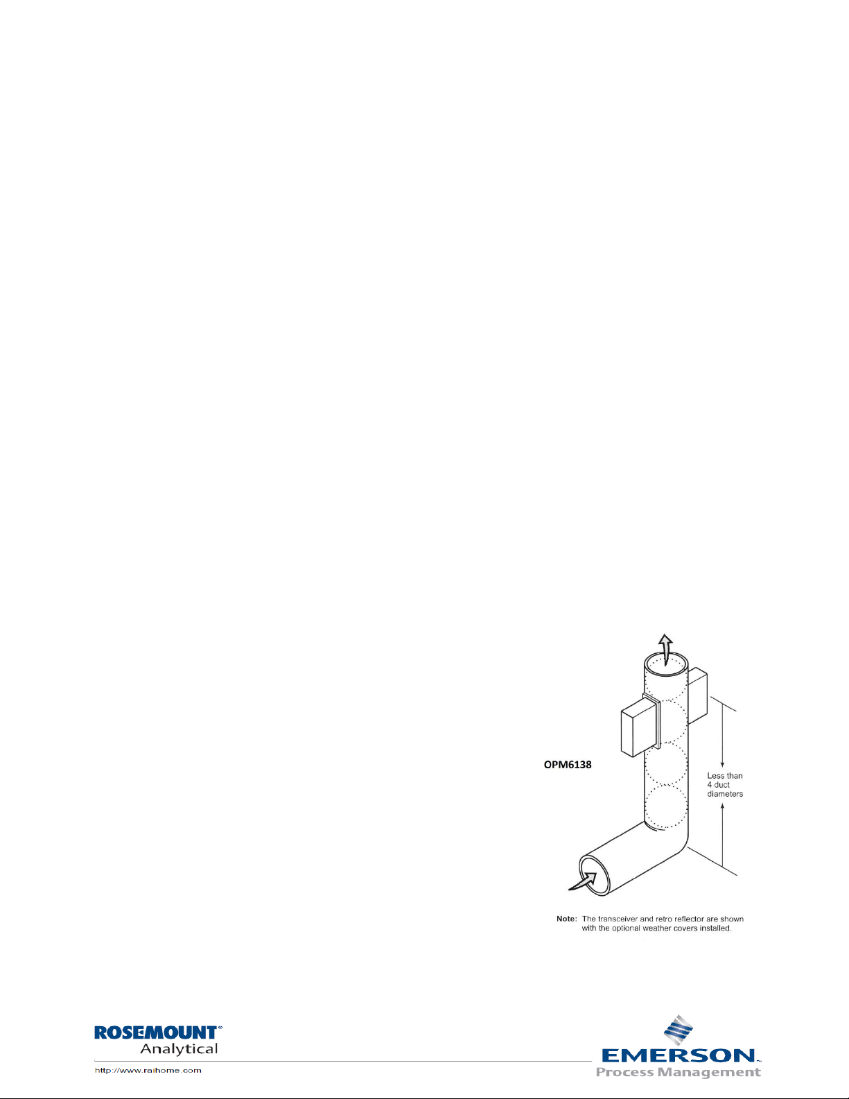
4) If a transmitter is to be located less than 4 duct diameters downstream from a bend, install
the transmitter in the plane defined by the bend, as shown in the figure below.
5) Ideally, locate the transmitter eight to ten stack diameters upstream from the stack exit
and three to five diameters downstream from any bends, junctions, or other constrictions
in the stack or duct.
For best results, mount the transceiver and retro reflector modules so the light beam is exactly
perpendicular to the stack or duct and the beam goes through the center. Do not install the transmitter
downstream of a wet scrubber. The water droplets introduced to the gas stream by such equipment will
interfere with the opacity readings. For an accurate measurement under these conditions, choose a
location upstream from a wet scrubber or a location downstream from the scrubber where the water
droplets are vaporized by the reheating of the gas. The stack exit correlation is especially important to
verify. If possible all dimensions should be verified by actual
measurements. Measure and record inside stack dimensions at the
measuring point and at the stack exit, and compute the Optical Path
Length Ratio (O.P.L.R.). Check that the calculated and the O.P.L.R.
found in the Factory OPLR Check step found further in this section
are within +/- 2%.
Page | 11
Page 12

Instruction Manual 2.1
Lt
Lx
OPLR*2
50.0
120*2
120
OPLR
Stack Exit Correlation Computations
NOTE: The stack exit correlation is especially important to verify. If possible, all dimensions should be
verified by actual measurements. Using the instructions below verify that the values are correct as
displayed in the About page.
Lx/Lt is the ratio of the inside diameter at the top of the stack to the inside diameter of the stack where
the instrument is located. If the ratio is greater than 1.0, the exit opacity will be greater than the opacity
at the instrument location. The OPM4001 uses this correction factor to calculate the stack exit opacity. It
is not practical to have an Lx/Lt factor much greater than 2.0 because the error of the instrument
increases as Lx/Lt becomes greater.
Lx = inside stack diameter at stack exit.
Lt = inside stack diameter at the transmitter location.
Lf = flange to flange distance between the transceiver and retro reflector unit.
1) Measure and record Lx and Lt and compute the Optical Path Length Ratio (OPLR).
2) Check that the calculated value and the
OPLR found in the 2nd About page are within
±2%.
3) Example: A stack with a 120 in. (3048 mm)
stack exit ID and a 120 in. (3048 m) path
length.
4) Enter the exit
diameter (Lx) and measured diameter (Lt) in
the control unit. Refer to Section 4:
Operation, for info on using the control unit.
Page | 12
Page 13

Instruction Manual 2.1
Choose an installation site; the primary considerations for choosing a site for the OPM4001 are
accessibility, ambient environmental conditions, and locating the unit to obtain a representative sample
of the process. Review the excerpt from the Federal Register in appendix for suggestions before
selecting an installation site. The following general guidelines should also be considered.
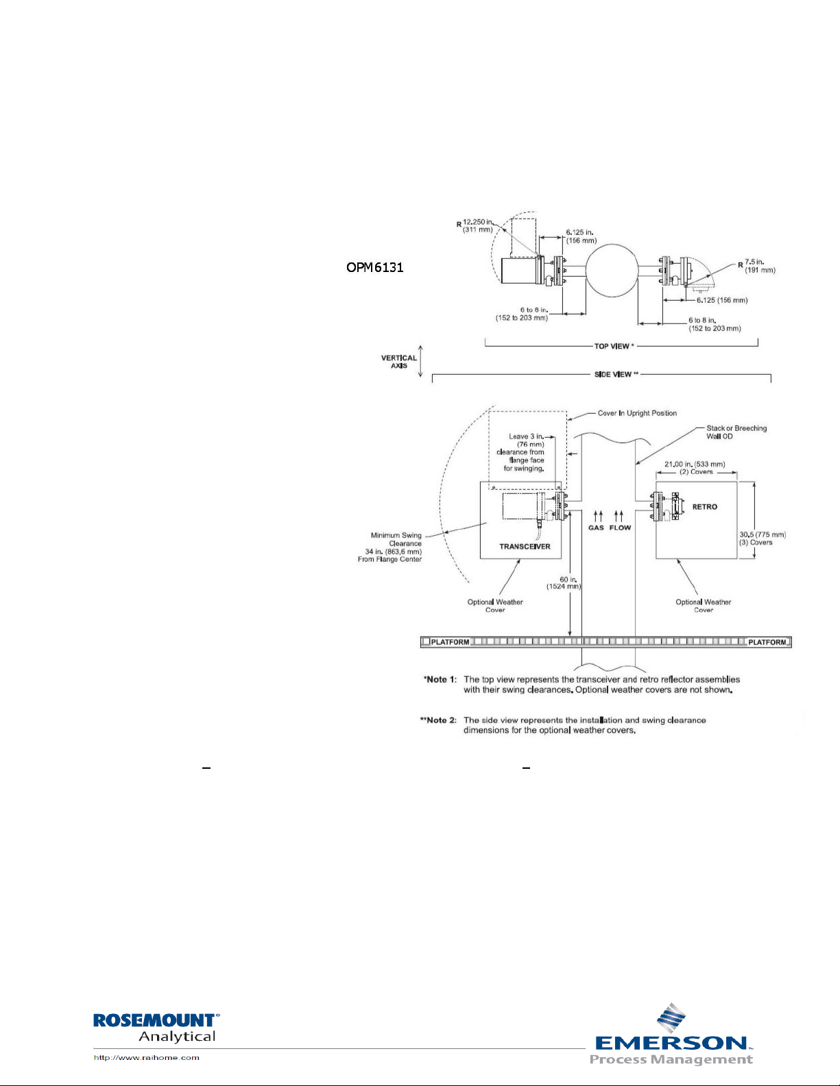
Sensors height from Platforms, walk way/ decks, etc, A platform or walkway must be available for access
to the weather covers. The optimum condition would have the mounting flanges and weather covers
approximately 5 feet up from the floor. Railings and other obstructions should allow the weather cover
to swing clear as shown in the installation drawings.
Locate the stack-mounted units in an area with ambient temperatures between -4 o to +130o F.
(Consult the factory for other temperature ranges.) Areas that are clean and dry are desirable. Avoid
areas with condensation.
Maintenance intervals are directly related to the installation environment. Intervals can vary from 2 to 3
months in fairly clean
environments, to twice a
month in dirty environments.
Lens cleaning is a function of
the ambient conditions and
cleanliness of the purge air.
Locate the instrument to
avoid excessive vibration or
shock.
Locate the control unit in an
easily accessible area with
temperatures between +32o
to 122o F. To permit the
operator to read and/or
change controls, the unit
should not be mounted
higher than five feet from
floor level.
Stack exit, Locate the transceiver more than two stack diameters down from the stack exit is
recommended.
Page | 13
Page 14
Instruction Manual 2.1
Installation – Mechanical
A review of the drawings and procedures provided will help to produce an error free installation.
However, there are important additional points that must be observed. The beam of the instrument
must be kept in the horizontal plane; the transceiver cannot be rotated more than +/- 10 o from vertical.
The weather covers must be
installed vertically plumb.
Installation and wiring diagrams are
found at the end of this manual.
Please review all drawings prior to
starting installation or wiring. If you
have any questions please contact
our Customer Support Center (CSC)
Phone: 1-800-433-6076 or 1-440914-1261
E-mail: GAS.CSC@emerson.com
Installation procedure - stack
flanges
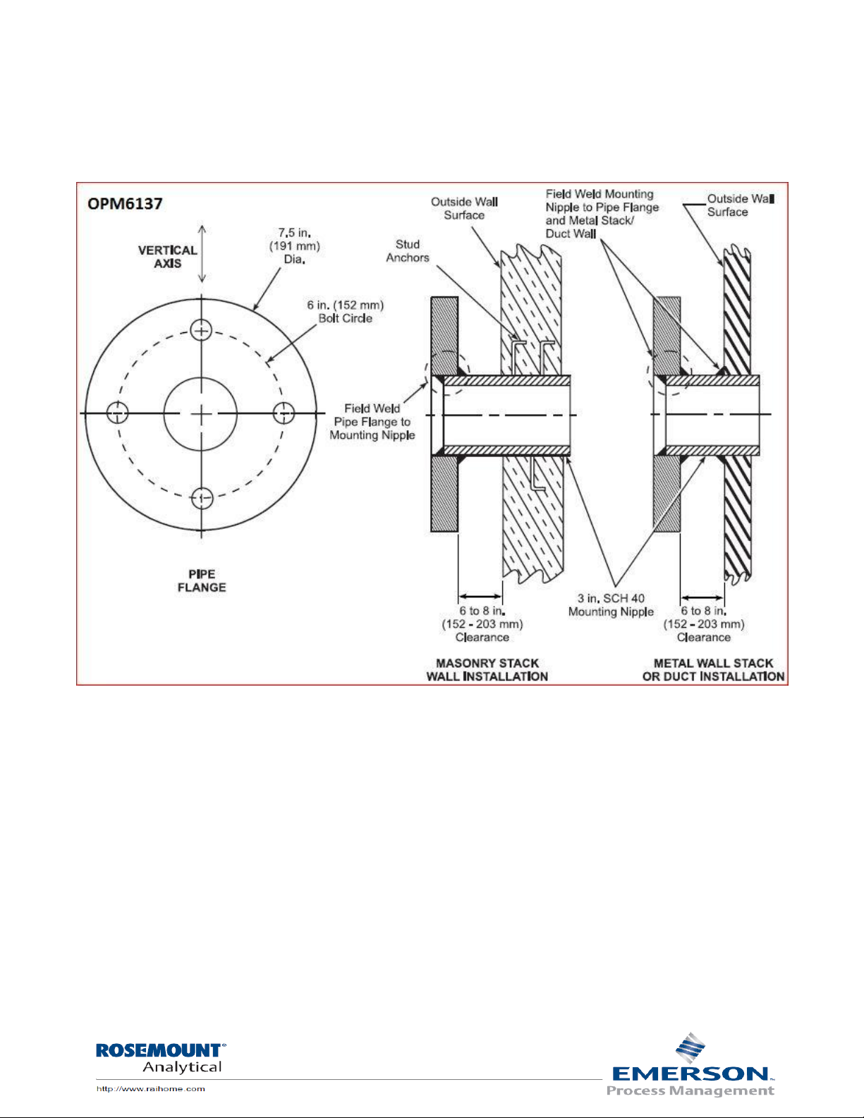
For an opacity monitor, the
customer is required to supply and
install two 3" I.P.S. flanges at eye
level directly across from each
other. The flange faces, mounted
on pipe stubs, should be
approximately 6" to 8" from the
stack or insulation. On completion
of the installation, the flanges must
be aligned so that the total
deviation of the light source flange
relative to a common centerline,
does not exceed +1o and the retro reflector flange does not exceed +3o .
Flanges should be mounted approximately 5 feet up from the deck of platforms, roof or walk way.
At installations where conditions permit, this may be accomplished by using a piece of 2 1/2" pipe
suspended across the stack protruding far enough to allow slipping the 3" flange pipe assemblies over
each end and welding in place as shown on the following page.
Page | 14
Page 15

Instruction Manual 2.1
Any deviation up to the previously specified limits can be adjusted out during the installation and
alignment of the light source and retro reflector with the system's alignment adjustments.
Where installations do not permit the use of the aforementioned method, the following procedure will
accomplish the same results. (See drawing EMS1002. An alignment tool can be purchased from the
factory to insure accurate alignment.
Accurately locate
one 3 1/2"
diameter hole
(large enough to
accept the 3" pipe)
and the other hole
approximately 1/2"
diameter, directly
across from each
other. Attach the
alignment tool to
the flange/pipe
assembly and
insert the pipe into
the 3 1/2" hole in
the stack wall.
Align the assembly
with the 1/2"
diameter hole on
the opposite side
by viewing through
the alignment tool
and weld the pipe
in place. Care must
be exercised when
welding to
maintain
alignment.
The 1/2" diameter
hole should now be
enlarged
approximately 3 1/2" to accept the other flange/pipe assembly. Proceed in the same manner, installing
the assembly with the alignment tool attached, and weld in place maintaining concentric alignment with
the 3" pipe previously installed on the opposite wall.
Page | 15
Page 16
Instruction Manual 2.1
Flange to stack installation
Page | 16
Page 17

Instruction Manual 2.1
Air purge/Weather cover mechanical Installation
Page | 17
Page 18

Instruction Manual 2.1
Mounting the air plenum and weather covers
WARNING! Control unit, Transceiver & Retro serial numbers must match.
After the installation site has been selected and the platform requirements have been met, the
mounting flanges should be installed and aligned as described on Drawings EMS - 1001 and EMS - 1002.
Flanges should be installed with the mounting faces on the vertical plane.
1) Before installing the Transceiver, Retro reflector or any type of weather cover remove
the air plenum from both the
Transceiver and retro reflector.
Removal will make the installation
easier and less chance of damage
while mechanical attachment of the
air plenums and optional weather
covers when provided.
2) If the transceiver and retro reflector
have been shipped from the factory
with the air plenum attached, unclip both hold down latches, swing
open and lift up & off the hinge pins.
Place the Transceiver and retro in a
safe place.
3) The air plenum is attached to the customer supplied 3" pipe flange by four 2 1/2" long
5/8-11 bolts. Working from the 3" flange the correct assembly is; gasket then air
plenum.
4) If you have weather covers remove the two (2)-weather cover hood hinge pins located
on the upper right and left hand corner of the hood. The air plenum and weather
cover are attached to the 3" pipe flange by four (4) 2 1/2" long 5/8-11 bolts. Working
from the 3" flange the correct assembly is; gasket, weather cover mounting plate,
gasket, mating flange & air plenum. Place the 5/8-11 bolt through the top hole of the
middle plate. Place a flat washer between the middle plate and mating flange and pass
the bolt through. Slip a split lock washer over the bolt and secure with a nut. Repeat for
the remaining three mounting bolts.
5) Any wiring or air hoses can be connected now.
Page | 18
Page 19

Instruction Manual 2.1
Transceiver and retro reflector assembly
6) Attach the Transceiver and Retro reflector to the air plenum assembly by placing them
on the hinge pins.
7) Close transceiver & retro and
secure in place with the two
hold down latches.
8) The air-purge blowers should
be powered up at this time to
prevent stack particulate from
accumulating in the nipple
and air-purge housing.
Caution: If installed location has a positive
pressure the air-purge system must be
used continuously during installation to
prevent process gases from contaminating
optical surfaces or over heating instrument
electronics. If the system is shut off for more than momentary interruptions, the instrument may be
damaged. Failure to provide continuous air-purge may void the warranty.
All wiring from the control unit to the transceiver should be completed at this time.
NOTE: THE AIR PLENUM ASSEMBLY FOR BOTH TRANSCEIVER AND RETRO MUST BE INSTALLED AS
BELOW, I.E. THE PINS ON THE LEFT SIDE POINTING UP!
Page | 19
Page 20

Instruction Manual 2.1
When power is first applied press ESC to display the Main page.
The left, right, up, down arrows are used to move display arrows or move
to other pages.
The ESC button is used to move back from the page you are on to the
previous page.
The enter or return button is used when entering variable. Press it
and the variable will change from steady to blinking, enter the new value
and follow screen tip at the bottom to complete the operation.
The info button is used for setting the PLC functions. This is not used
during normal operation. When required the use of the functions will be
explained in this manual.
The key pad is used to enter values.
The +/- is used when (–) sign for values are required.
These buttons are not used on this model.
Section 3 Remote Control Unit (RCU) operation Page Description
RCU buttons
About page
Page | 20
Page 21

Instruction Manual 2.1
When power is first applied press ESC to display the screen
for the operator to select the function of interest by pushing
the Up or the Down Arrow to select the function desired,
press the return/enter button .
By pushing UP or the DOWN arrow you can select the OPM4001
Display, Setup or About pages. Use the return/enter button to enter the
page (screen) you desire.
To get to the About page scroll down to
About and press the right arrow button to
enter the 1st page of the about page. This
will display the Model & s/n, Date of
manufacture and Flange to Flange.
About page 2 displays Modbus network,
Stack exit I.D., Path length I.D. and OPLR
(Optical Path Length Ratio).
Page | 21
Page 22

Instruction Manual 2.1
Start up Verifying instrument operation and configuration
Zero/Span Check
For assistance with problems, please call the Customer Support Center (CSC).
Phone: 1-800-433-6076 1-440-914-1261
In addition to CSC, you may also contact Field Watch. Field Watch coordinates Emerson Process
Management’s field service throughout the U.S. and abroad.
Phone: 1-800-654-RMST (1-800-654-7768)
Worcester Polytechnic Institute may also be reached via the Internet through e-mail and World Wide
Web:
e-mail: GAS.CSC@emerson.com
World Wide Web: www.raihome.com
World Wide Web: www.raihome.com
Alignment procedure must be completed as outlined in Section 2.
Power applied to both the control unit and the sensors for a minimum of 30 Minutes before any
adjustments are attempted.
The zero calibration has been set at the factory by placing the instrument on an optical bench using the
flange-to-flange dimensions specified by the customer and recorded in the customers final test report.
This zero value is critical as it can offset smoke measurement plus or minus if not correctly set. The
measurement reflector contains an aperture that is chosen during the factory calibration and is fixed.
The Transceiver is aligned with the beam centered on the retro reflector and the electronics is adjusted
to produce a zero opacity value.
The calibration zero reflector is adjusted to provide a low value typically 1-2% and the span filter upscale
value is recorded and entered in the set up page under “Fault setup" When the system enters a manual
or auto cal check cycle the current zero and span values are checked against the stored values. If either
the zero or span current value exceeds the stored value by +/- 2% opacity the fault system will energize.
Page | 22
Page 23

Instruction Manual 2.1
Initiate a Z/S check by pressing the F1 button. The next screen will
ask you for a selection; press Enter to choose “Yes”. The screen will
return to the Display and the Right column will show In Cal icon.
When the zero check “Instant value” stabilizes (@15 seconds) record
the zero value. The Zero check will remain for 3 minutes, next will be
Span and will last for another 3 minutes. When Span is stabilized
record the span upscale value. The system will automatically return
to monitoring the process at the 6 minute point from cal start. You
will know this because the In Cal icon will turn off.
Check to see if the controller has the same values by pressing ESC
and scroll down to the Setup and press return/enter button
you will be at the password page. Enter 1234 from key pad and press
the return/enter button.
Scroll to Cal Z/S Value setup and press the return/enter button .
The true span check will be blinking. If zero and span values are the
same as you recorded +/- 0.5% opacity do nothing just press the ESC
button. Should the displayed values be greater than +/- 1.0% but less
than 3% from your recorded values enter the recorded values. Press
the right arrow to highlight the value to change. Press the
return/enter button and use the key pad to enter your value. Press
the +/- dot button above the return/enter button for decimal point.
When correction is made press the return/enter button to save (it
will stop blinking and move to the next value).
The Fault squelch timer should be left at 1 Min.
The fault timer is that time from fault detection to initiation of the
fault alarm and should be not less than 10 seconds.
The ( –ve) negative opacity fault YES= on, NO= Off.
When you are finished press the ESC to exit.
Page | 23
Page 24

Instruction Manual 2.1
NOTE: If the Zero or Span value stored is +/- 3% Opacity from your
recorded value contact our service department because it may
indicate other adjustments are required.
Page | 24
Page 25

Instruction Manual 2.1
Pressing ESC will get you back to the selection page, scroll to OPM4001
Display and press return/enter button the process opacity display page
will be displayed:
Upper line; Next cal in HH:MM:SS
Middle line; Instant opacity %
Bottom line; 6 Minute average opacity %
Pressing the up or down arrow you can scroll to the 3 display pages that is
best for your application.
Page 1 is a split screen with instant and average opacity. NOTE: If input goes
negative a 4th screen will appear, when signal goes positive it will return to
page 1 the default page.
Page 2 is average opacity only.
Page 3 is Instant opacity only.
Scrolling multiple main display pages
Page | 25
Page 26

Instruction Manual 2.1
Password 1234 - From any screen press ESC
until the Main, setup and about screen is
visible. Scroll to Setup and press the
return/enter button. The password is 1234.
Alarm set point - return/enter button and
set the alarm set point from 0-99% and
the alarm delay – In seconds. Press enter
to set, ESC to exit.
Calibration Cycle setup – Press
return/enter button and set the
frequency you want the cal cycle to
initiate. EPA regulations call for 24hr.
The OPM4001 will initiate the cal cycle if
Cal trigger is “Internal”. To use an
external command scroll down to cal
trigger and choose external by pressing
key pad #2 then press return/enter
button to set. Input momentary ground
to I3.
Note: No input to I3 and External selected the system will not go into cal
cycle, however you can still use the F1 button to force an manual cal cycle.
Password protected parameters
Page | 26
Page 27

Instruction Manual 2.1
Alarm Auto/Manual setup – Press return/enter
button to enter. Choose between 1-auto or 2manual.
Auto means when the high opacity alarm has
been activated and when the level of smoke
drops below the alarm point the alarm contacts
02 & 04 and icon will reset automatically.
Manual reset means when the high opacity alarm
has been activated, pushing the return/enter
button 04 contact will de-energize but 02 will
remain energized. When the level of smoke drops
below the alarm point the return/enter button is pushed and both 02 &04 will be deenergised.
Output type setup – Press return/enter
button to enter. “Output type” refers to
the 4-20mA outputs.
Ins – instant opacity, z/s outputted during
cal cycle.
Avg – 6 minute opacity average z/s
outputted during cal cycle.
Last - instant opacity, last value is held
during cal cycle.
Note: Last should be used if you are using the output for process control
signal.
Output scaling setup – Press return/enter button to enter. Set Ch 1 or 2
to desired opacity range i.e, for 4ma to
represent minimum opacity and 20mA to
represent maximum opacity. The 20mA
value of 99.9 is used to represent 100%.
Note; For CFR 40, PS-1 the set 4mA to -5%
To get negative values press +/- once for
negative then button 5 then +/- again for
the decimal placement. i.e, Ch.1 4 mA: -
5.0 % 20mA: 99.9%
Page | 27
Page 28

Instruction Manual 2.1
MODBUS I.D. – Press return/enter button
to enter and input the node number (1 to
32) desired press Press return/enter
button to to set then ESC to exit.
Write:
Remote Cal. Initiate
MB 51
Initiate cal =1
In maintenance
MB 49
In Maint. =0, Not In Maint.
=1
Power status
MB 50
Lost power to SM (service
module) =0, Power OK =1
T2 Signal
MB 34
Signal OK =0, Lost signal =1
-ve opacity
MB 37
Positive opacity =0,
Negative Opacity =1
Zero Cal Fail
MB 38
Fail =1, Not fail =0
Span Cal Fail
MB 39
Fail =1, Not fail =0
Section 4 Modbus
Modbus Setup
Modbus Write
Page | 28
Page 29

Instruction Manual 2.1
MB = Modbus Poll Read Discrete inputs (100001….20000)
MI = Modbus Poll Read Holding (40000…50000)
Read:
0% to 100% (x.x) instantaneous opacity
MI 35
Read
0% to 100% (x.x) average opacity
MI 98
Read
Relay 05 (Zero DAS)
MB 43
Zero, not cal = 0, in cal =1
Relay 06 (Span DAS)
MB 44
Span, not cal = 0, in cal =1
Relay 07 (No Air flow)
MB 45
OK =0, Not OK =1
Relay 03 (High alarm Audible)
MB 46
No alarm =0. Alarm =1
Relay 04 (Fault)
MB 47
No fault =0. Fault =1
Relay 02 (High alarm)
MB 48
No alarm =0. Alarm =1
Alarm Set point
MI 22
Read
Alarm delay
MI 24
Read
Common fault individual blocks:
Modbus Read
Page | 29
Page 30

Instruction Manual 2.1
RS/485 Communications and connection
Port 2, 6-pin R J25 connector Pin 1 (+), Pin 6 (-). RS-485 cabling may be up to 2000 feet in length. Belden
P/N 3106A cable is recommended.
If not specified in the original order default is as follows. NOTE: The following communication
perimeters cannot be changed in the field the controller must be returned to the factory.
Baud Rate 9600
Data Bits 8
Parity None
Flow Ctrl None
Timeout 0.2 seconds.
RS485: Pin out
Use RS485 to create a multi-drop network containing up to 32 devices.
Note: port #1is set to RS485
Note that the ports are not
isolated. If controller is used with a
non-isolated external device, avoid
potential voltage that exceeds +/10V. To avoid damaging the
system, all non-isolating device
ports should relate to the same
ground signal.
Use shielded, twisted pair cables.
Minimize the stub (drop) length leading from each device to the bus.
Ideally, the main cable should be run in and out of the network device.
Do not cross positive (A) and negative (B) signals. Positive terminals must be wired to positive
and negative terminals to negative.
Page | 30
Page 31

Instruction Manual 2.1
Section 5 Output Connections
Channel #1 and 2, 0-100% Opacity 4-20mA outputs to recording devices
(Maximum 500 ohm device load) Connect the (-) minus wire from your device to the bottom connector
terminal 0V and the (+) plus wire from your device to the terminal AO for channel 1 and AI for channel 2.
Page | 31
Page 32

Instruction Manual 2.1
Alarm output Connections
Alarm outputs are SPST relays. There are 2 groups each group has its own common, See drawing
OPM6142 for connection details. Relays are rated at: 30Vdc, 3Amp max per relay and 8Amp max per
common. If you need to switch high voltage AC contact the factory for assistance.
Group 1:
Reference drawing OPM6142
00 & 01 - DO NOT USE dedicated for z/s command lines to service module.
02 - High opacity alarm relay
02 Set point and delay are chosen in the setup page. Choose Auto or manual mode in the setup page.
For 02 to be utilized as a boiler shut down you must select “Manual” in the alarm set up page.
03 - High opacity Audible alarm relay
03 may be used for audible alarm and can be reset (acknowledged) even if the opacity is still above the
set point.
Group 2:
Reference drawing OPM6142
04 - Common FAULT RELAY
Faults are; Maintenance, Power status, T2 Signal, -ev
(Negative opacity), Zero cal and Span cal.
Note: the –ev (Negative opacity) can be turned on or
off by the user see page 25 for instructions.
05 - ZERO to DAS relay
Cal in progress or zero is by dry contacts on terminal
05 group 2 common. This contact remains closed
until cal is completed, i.e. both zero & span.
06 - SPAN to DAS relay
Cal span is by dry contact on Terminal 06 & group 2 common. This contact remains closed during Cal
span.
07 - Air purge alarm relay
Page | 32
Page 33

Instruction Manual 2.1
Analog outputs 4-20ma
The OPM4001 comes with two 4-20mA output channels. The ranges are set during final test to the
information supplied by the customers. Field changes can be made in the set up page. Maximum output
Loop compliance is 500 Ohms.
Channel 1: 0V & A0 supplies the opacity signal to the service module 14 & 13 (on TB1, OPM6142) for
display at the service module.
Channel 2: 0V & A1 can be used for DAS, recorder etc.
Page | 33
Page 34

Instruction Manual 2.1
Other output connections possible
To utilize an external device (max 250 ohm) in Ch1 current loop:
To utilize an external device in Ch2 current loop (max 500 ohms total):
To check devices such as recorders or DAS are responding correctly use the following procedure; On the
control unit front panel press the F1 Push button to put the system in a maintenance zero and span
cycle. Both outputs will correspond to the opacity display value.
Page | 34
Page 35

Instruction Manual 2.1
Section 6 Clear Path Adjustments
Service module
Page | 35
Page 36

Instruction Manual 2.1
Clear on stack zero and span calibration
The instrument has been calibrated at the factory to specifications received with the order and if the
actual dimensions of the flange to flange are exactly as received the calibration adjustments required
will be minimal or none at all. The following adjustments are for the first time the instrument is
installed. To calibrate or adjust the OPM4001 use the following steps.
NOTE: Calibration must be performed with the process shut down to produce a clear stack condition. If
a clear conditions is not possible go to “Off stack zero calibration” procedure later in this manual.
Before proceeding clean both transceiver and retro reflector lens.
Remove the transceiver cover (Always disconnect power when removing or replacing the transceiver
cover) by removing the screw below the target viewing window and pulling the cover straight back until
it clears the Optical plate.
To complete this procedure the following items are required: Micro-turn 200 on-line test kit (p/n
6A00188G07) a manual for the audit device is included with the device.
1. Swing both the retro and transceiver open and clean the protective windows. Return both
to the closed position.
2. Verify alignment, returning beam is centered on the TTL target.
3. On the transceiver remove the screw below the target viewing window and pulling the
housing straight back until it clears the optical plate.
4. On the Service Module (Figure 2) the normal/test switch must be in the “Normal” position and
the Opacity/ T2 is in “Opacity” position. NOTE: All adjustments are on the PCB 222-
1667 (p/n 1A99993H03 for replacement).
5. Adjust the 20 turn Zero potentiometer on board
222-1667 marked "PT -1", CW until you increase to
about 20% opacity, then slowly turn the PT-1 CCW
until you have Zero % opacity, 0-1% opacity.
6. Install the Micro-turn 200 on-line test reflector on
the transceiver and screw the device to the
transceiver with the mounting screw. With the
thumbwheel adjust the on-line reflector for the same opacity as in
previous step and lock it in place.
7. Place the highest value filter (for best results at least a 0.8 O.D.) in the slot provided. Adjust
the Span potentiometer on board 222-1667 marked "PT -3" for the filters correlated value
on the service module opacity display equals to the correlated value. See section six (6) for
filter correlation formulas.
8. Remove the filter and adjust the Zero potentiometer PT-1 for 0-1%.
Page | 36
Page 37

Instruction Manual 2.1
9. Insert the High filter again adjust PT-3 for its value, repeat steps until the values come within
0.5 % Opacity.
10. Remove the on-line test reflector and replace the transceiver cover and secure the
transceiver in place. You must complete "Zero Reflector Adjustment" procedure next.
Page | 37
Page 38

Instruction Manual 2.1
Zero reflector adjustment
After a clear or off stack zero has been performed the zero reflector needs to be adjusted.
1. Find and record the zero offset value
found in the set up page under "Zero
Cal Value".
2. On the service Module place the
Opacity/ T2 switch in the Opacity
position to observe the correlated
opacity on the digital display.
3. Swing open the transceiver and initiate
a zero with the zero switch on the
service module to raise the zero
reflector into place. Observe and
record the zero value after 30 seconds.
Return the mirror to normal resting position by returning the zero switch to operate
position.
4. If required, insert a 1/16" Alan wrench into the adjustment set screw located on the top
of the zero reflector. Turn the set screw clock-wise 1/8 turn.
5. Remove the Alan wrench and initiate a zero utilizing the zero switch on the service
module and after 15 seconds observe the reading is moving toward the desired value. (if
value is away from desired repeat step 4 turn set screw C.C.W.)
6. Repeat steps 4 & 5 each time making small 1/8-turn increments until the desired value
is reached. Cycle 2-3 times more waiting 15 to 20 seconds between cycles to assure unit
repeats desired value +/- 0.5% Opacity. Swing transceiver into operate position and
secure in place. Record the zero final value.
Span filter value
1. With the zero switch in zero, place the span switch in span. Span is not adjustable, final
value is a function of filter value, transceiver calibration and OPLR. Record the final
value.
2. Return both zero and span switches to operate, normal/test to normal, T2/Opacity to
Opacity.
Record the zero/span values
1. To record the final values you will need to enter the zero and span into the set up page
under “Cal Z/S Value setup “. This completes the calibration.
Page | 38
Page 39

Instruction Manual 2.1
Off stack zero calibration
This procedure may be used if: A clear stack condition is not possible and the zero appears to be
incorrect or if the flange to flange distance on site are different than the original factory set up.
This procedure may be used if: A clear stack condition is not possible and the zero appears to be
incorrect or if the flange to flange distance on site are different than the original factory set up.
Remove the transceiver and retro reflector from the hinge pins, remove the service module and install
the system on portable off stack test stands (p/n 1A99993H37) and at the correct flange to flange
distance plus 11 inches. The additional 11 inches compensates for air plenum spacing, as the air
plenums are not used for the off stack zero calibration.
1. Clean transceiver and retro windows.
2. Connect the control unit with the cables that came with the Off Stack kit and apply
power to the system.
3. The retro reflector must be level.
4. Follow instruction for "Clear on stack zero and span calibration".
Page | 39
Page 40

Instruction Manual 2.1
2100*
100
1
11
5.0
2
OP
Op
M
%5.54100*
100
1.23
11
5.0
5.1
Section 7 Filter correction formula
If you have an OPLR (correlation factor) other than 0.5 your slides will read differently. To calculate what
the slide will read with another OPLR use the formula:
Where:
OP1 = Standard filter Value in %
M2 = OPLR for your instrument
OP2 = Standard Filter value at your OPLR in %
Example:
Standard filter value is 23.1% what will it read at OPLR of 1.5?
Filter re-calibration is available from EMS and if not regulated by EPA regulations in your State to a more
frequent schedule we suggest you re-calibrate at the minimum of once a year. If you have filters from
other manufacturers we can also calibrate them as well (call for pricing). Filters are tested per USA Code
of Federal Regulations 40CFR60 Appx. B, Performance Specification 1, Section 7.1.3 Attenuation
Calibration.
Page | 40
Page 41

Instruction Manual 2.1
Filter certification
QA/QC testing of the filters at an interval of not more than 6 months is recommended. Filter
certification, replacement or additional Neutral Density .
Neutral Density Filters for Micro-turn 200 are calibrated on a Perkin-Elmer Lambda Series 6 / PECSS
Spectrophotometer per Federal Environmental Protection Agency specifications. These specifications
are contained in the Code of Federal Regulations 40 CFR 60, Appendix B, Performance Specification 1,
Attenuator Calibration. The filters are scanned over the visible region from 380 to 780 nanometers in
one nanometer steps and the resulting transmittances of the filter are weighted to the Source C Human
Eye Response by multiplying each value by its associated response factor. The corrected values of
transmittance are converted to % Opacity and the value is recorded on the filter and associated chart.
Page | 41
Page 42

Instruction Manual 2.1
Section 8 Preventive/Corrective Maintenance
Preventive/corrective maintenance schedule
Daily:
Check Zero/Span marks are within specification (+/- 2%)
Check for fault conditions
Monthly or as required:
Clean transceiver and retro windows
Check alignment, correct if necessary
Check air filters replace if necessary
Quarterly:
All daily and monthly checks
Perform COM Audit per EPA regulation 40 CFR, 60 App. B, PS-1.
Replace air filters
Check all air hoses and clamps for tightness and wear, correct as necessary
Check weather cover gaskets for leakage
Check all bolts for tightness
Check all electrical connections are secure
Check air blower for excessive noise
Assure that airflow switch is operating properly
Page | 42
Page 43

Instruction Manual 2.1
Yearly:
Clear stack or off stack zero
All quarterly checks
Remove transceiver and retro, clean air plenum
Replace any worn hoses and gaskets
Clean inner optics if necessary
Check all system operations
General
Corrective and preventive maintenance schedules should be adjusted according to site specific
conditions to ensure the maximum availability of accurate measurement data. Routine checks should
be implemented to:
Observe and correct the operation of the air-purge system giving particular attention to keeping the
optical path within the mounting flanges clear of dirt build-up.
Observe and correct the operation of peripheral accessory equipment such as recorders, computers,
etc.
Observe and correct the stack zero measurement whenever a clear stack condition exists. Care should
be exercised to ensure that both transmittance and opacity measurements are at their prescribed
values.
Verify that instrument operating manuals are available and that maintenance logs are properly
maintained and reviewed.
Every 3-5 Years:
EMS recommends periodical, depending on the severity of the sensor locations 3-5 years between
overhaul of our opacity system to keep them working at their optimal level. Overhauls become
necessary do to the fact that over time dust, out gassing of electronic parts, removing protective covers,
etc., manifest itself as overall optics degradation causing more frequent adjustments and poor
performance of the opacity monitor.
Page | 43
Page 44

Instruction Manual 2.1
For assistance with problems, please call the Customer Support Center (CSC).
Phone: 1-800-433-6076 1-440-914-1261
In addition to CSC, you may also contact Field Watch. Field Watch coordinates Emerson Process
Management’s field service throughout the U.S. and abroad.
Phone: 1-800-654-RMST (1-800-654-7768)
Worcester Polytechnic Institute may also be reached via the Internet through e-mail and World Wide
Web:
e-mail: GAS.CSC@emerson.com
World Wide Web: www.raihome.com
World Wide Web: www.raihome.com
Warnings and Safety Guidelines for user safety and equipment protection
Page | 44
Page 45

Instruction Manual 2.1
Problem
Possible Cause
Remedy
Control unit reads 99%, Alarm icon is on,
Fault message T2 4-20mA FAULT, service
module meter in T2 reads -20 or higher.
Transceiver current loop
to the control unit is open
Operate/test switch must be in
Operate.
Check wiring for open from control
unit I6 & 0V to terminal 17 & 16 at
service module location.
Alignment is good but control unit reads
high opacity or erratic in normal, zero &
span mode, service module meter in opacity
reads high or erratic.
1- Reference voltage TP-2
on signal processor 1667
is lower than 9.3V
2- Main lamp out
1- Adjust lamp drive PT-2 on the
power modulator 1668 until
Reference voltage TP-2 on signal
processor 1667 is 10.0 +/- 0.2Volts.
2- Replace main lamp assembly
Control unit reads High, zero/span values
are OK
1- Smoke
2- Alignment is out
1- Correct process
2- Adjust alignment until centered
on target.
High dust alarm and /or cal fail cal message
Transceiver window
and/or zero mirror is dirty
Clean window and or zero mirror
Control unit reads High, zero/span values
are OK, alignment is good
Dirt built up in flanges
Swing open transceiver & Retro.
Clean flanges with push rod.
Air purge icon on in the lower right corner
of the Main Display
No air flow
Replace air blowers as necessary
Replace air filters as necessary
Tighten hose clamps as necessary
No stack power fault message
Service module lost
power or failed
Check power, check SM fuse.
Replace as needed
Trouble Shooting
Page | 45
Page 46

Instruction Manual 2.1
Problem
Possible Cause
Remedy
Maintenance Mode message
Maintenance switch or
maintenance function is
on
1- Control unit zero/span
key was pressed.
2- Service module
zero/operate switch in
zero, span/operate switch
in span
3- Service module
test/operate switch in test
Return all to operate
positions.
Control unit blank
Control unit fuse open
Replace and check for
shorts in the power supply
or individual boards.
Trouble shooting -continued
Page | 46
Page 47

Instruction Manual 2.1
1A99993H03
OPM T Signal processor with
detector board assembly installed.
X
Transceiver
1A99993H04
Power Supply/Modulator BoardPCB
X
Transceiver
1A99993H06
Zero reflector iris assembly with
rotary solenoid, reflector tape and
zero arm for Opacity Transceiver .
X
Transceiver
1A99993H08
Replacement Air flow switch for air
purge blower.
X
Transceiver
Retro reflector
1A99993H09
8 Pack Air filter replacement
element (ID 1.5 OD 4.5 HT 5.875
Black)
X
Transceiver
Retro reflector
1A99993H11
P1 - Service Module output cable
assembly
X
Control Unit
Service Module
1A99993H12
P2 - Transceiver output cable
assembly
X
Transceiver
Service Module
1A99993H13
Service Module Assembly with
Digital display, local zero/span
and test jacks.
X
Service Module
1A99993H30
OPM4000 series control unit to
service module 10' test cable.
X
Control Unit
Service Module
1A99993H35
OPM3000/4000 Series Opacity
Detector Board-PCB
X
Transceiver
Section 9 Spare parts
Page | 47
Page 48

Instruction Manual 2.1
1A99993H36
Retro Assembly Drop on pin type
3-15Ft.
X
Retro reflector
1A99993H37
Off the Stack Opacity Test Stand
for OPM3000/4000 series.
X
Transceiver
Retro reflector
1A99993H39
Pair of Opacity Air plenum Plant
Air Adaptors, accepts 1/4" or 1/2"
NPT
X
Transceiver
Retro reflector
1A99993H40
OPM3000/4000 Series Air Plenum
Assembly (with lift-off hinge),
opacity fits either Transceiver or
Retro.
X
Transceiver
Retro reflector
1A99993H41
OPM3000/4000 Series Opacity
Transceiver protective window kit,
3-screws, 1-150x50mm lens, 1-Oring, 1-lens retaining ring.
X
Transceiver
1A99993H43
OPM4001 Base Control Unit
Spare/Replacement
X
Control Unit
1A99993H45
OPM SD Standard Backup Card
(2GB)
X
Control Unit
OPM4000 Series Service Module
Zero-Span controller main PC
board.
X
Control Unit
Page | 48
Page 49

Instruction Manual 2.1
Section 10 Drawings
It is recommended to print drawings with the highest print quality.
OPM4001 control unit dimensions
Page | 49
Page 50

Instruction Manual 2.1
Page | 50
Page 51

OPM6142 1of3 - wiring
Page 52

Instruction Manual 2.1
OPM6142 2of3 - wiring
Page | 52
Page 53

Instruction Manual 2.1
OPM6142 3of3 - wiring
Page | 53
Page 54

Instruction Manual 2.1
RS485: Pin out
Use RS485 to create a multi-drop network containing up to 32 devices.
Note: port #1is set to RS485
Note that the ports are not isolated. If
controller is used with a non-isolated
external device, avoid potential voltage that
exceeds +/- 10V. To avoid damaging the
system, all non-isolating device ports should
relate to the same ground signal.
Use shielded, twisted pair cables.
Minimize the stub (drop) length leading from each device to the bus.
Ideally, the main cable should be run in and out of the network device.
Do not cross positive (A) and negative (B) signals. Positive terminals must be wired to positive
and negative terminals to negative.
Page | 54
 Loading...