

OCX 8800 O2 / Combustibles Transmitter Hazardous Area with Integral Electronics and LOI Local Operator Interface-Rev 1.3
Table of contents
 Loading...
Rosemount OCX 8800 O2 / Combustibles Transmitter Hazardous Area with Integral Electronics and LOI Local Operator Interface-Rev 1.3 Manuals & Guides

Instruction Manual
IM-106-880CIL, Rev 1.3
April 2017
Rosemount
OCX8800
Oxygen and Combustibles Transmitter
TM
Hazardous Area Transmitter with Integral Electronics and Local Operator Interface


HIGHLIGHTS OF CHANGES
Effective December 2007, Rev 1.1
Page/Section Summary
Throughout Updated manual number suffixes in page headers to indicate OCX configuration.
Changed references to HART Communicator te read Field Communicator in text and
illustrations.
Page 1-9 Added new illustration Figure 1-5 .
Page 1-12 Updated Product Matrices.
Page 1-13 Revised/updated Table 1-2 .
Page 2-2 Deleted obsolete CAUTION statement.
Page 2-10 Revised paragraph 4 listing of gases for calibration.
Page 2-14 Revised Figure 2-11 to indicate minim um pr ess ur e f or actuation of the blowback valve.
Page 2-15 Revised Figure 2-12 to indicate minimum pr es sur e for actuat ion of t he blowback valve.
Page 5-4 Revised 1st paragraph.
Page 5-5 Revised HART menu items in Figure 5-3, Sh eet 1 of 4
Page 5-9 Added new step 4 to both D/A Trim Procedures.
Page 6-3 Replaced steps 6 through 10 with a repeat of step 4 instruction.
Page 6-4 Revised steps 2 and 3.
Page 8-3 Revised "Ref Current Err" fault indication heading.
Page 8-7 Revised probable cause statements of "Cal Warning/Cal Failed" fault indication.
Page 9-5 Revised parts list for Sensor Housing Components.
Appendix A Updated multi-lingual safety pages.
Effective July 2008, Rev 1.2
Page/Section Summary
Page 4-3 Added note regarding cleaning the LOI screen before each use.
Effective April 2017, Rev 1.3
Page/Section Summary
Title page Removed Rosemount Analytic a l logo.
Updated Emerson logo.
Page 1-10 Updated Blowback Air specification.
Page C-1 Updated Return of Materials information.
Back page Updated to include new addresses, social media information, and Rosemount and
Emerson logos.


Instruction Manual
April 2017
OCX 8800
IM-106-880CIL, Rev 1.3
SECTION 1
Description and
Specifications
SECTION 2
Installation
SECTION 3
Configuration and
Startup
Table of Contents
Essential Instructions ........................................................................................ i
Preface ............................................................................................................... ii
Definitions .......................................................................................................... ii
Symbols .............................................................................................................. ii
Component Checklist ................................................................................... 1-1
System Overview .......................................................................................... 1-1
Specifications ..............................................................................................1-10
Mechanical
Installation ...................................................................................................... 2-2
Electrical Installation ..................................................................................... 2-7
Pneumatic Installation ................................................................................2-10
Initial Startup ................................................................................................2-16
Verify Installation ........................................................................................... 3-1
Initial Power Up ............................................................................................. 3-3
Set Test Gas Values .................................................................................... 3-4
OCX 8800 Reset Procedure ....................................................................... 3-4
SECTION 4
Using the LOI
SECTION 5
Using HART
Communications
SECTION 6
Calibration
Overview ........................................................................................................ 4-1
Display Orientation ....................................................................................... 4-1
LOI Controls ................................................................................................... 4-2
Overview ................................................................................................... 4-2
LOI Key Functions .................................................................................. 4-2
LOI Status Codes .................................................................................... 4-3
LOI Menu Tree .............................................................................................. 4-4
D/A Trim Procedures .................................................................................... 4-8
Overview ........................................................................................................ 5-1
Field Communicator Sig na l Conn ec tio ns .................................................. 5-1
Field Communicator PC Connections ........................................................ 5-4
HART Menu Tr
D/A Trim Procedures .................................................................................... 5-9
Overview ........................................................................................................ 6-1
Fully Automatic Calibration .......................................................................... 6-1
Operator - Initiated Autocalibration ............................................................ 6-4
Manual Calibration ........................................................................................ 6-4
ee .......................................................................................... 5-5

Instruction Manual
April 2017
OCX 8800
TOC-2
IM-106-880CIL, Rev 1.3
SECTION 7
Maintenance and Service
SECTION 8
Troubleshooting
Overview ........................................................................................................ 7-1
OCX 8800 Removal
and Installation .............................................................................................. 7-1
OCX with
Integral Electronics ................................................................................. 7-2
Repair Sensor Housing ................................................................................ 7-5
Sensor Housing Disassembly ............................................................... 7-5
Sensor Housing Assembly .................................................................. 7-15
Repair Electronics Housing ...................................................................... 7-25
Electronics Housing Disassembly ..................................................... 7-25
Electronics Housing Assembly ........................................................... 7-28
Replace Tube Fittings ................................................................................7-31
Remove Tube Fittings ..........................................................................7-31
Install Tube Fittings ...............................................................................7-32
Overview ........................................................................................................ 8-1
Grounding ................................................................................................. 8-1
Electrical Noise ........................................................................................ 8-1
Electrostatic Discharge........................................................................... 8-1
Total Power Loss .................................................................................... 8-2
Diagnostic Alarms ......................................................................................... 8-2
Fault Isolation ................................................................................................ 8-3
Alarm Relay Events ....................................................................................8-11
SECTION 9
Replacement Parts
APPENDIX A
Safety Data
APPENDIX B
SPA with HART Alarm
APPENDIX C
Return of Materials
Sensor Housing ............................................................................................. 9-2
Electronics Housing ...................................................................................... 9-6
O2 Cell and Heater Strut Assembly ........................................................... 9-9
Safety Instructions . . . . . . . . . . . . . . . . . . . . . . . . . . . . . . . . . . . . . . . . A-2
Safety Data Sheet for Ceramic Fiber Products . . . . . . . . . . . . . . . . . A-24
High Pressure Gas Cylinders . . . . . . . . . . . . . . . . . . . . . . . . . . . . . . A-30
Atex Clarification . . . . . . . . . . . . . . . . . . . . . . . . . . . . . . . . . . . . . . . . A-31
Overview . . . . . . . . . . . . . . . . . . . . . . . . . . . . . . . . . . . . . . . . . . . . . . . B-1
Description. . . . . . . . . . . . . . . . . . . . . . . . . . . . . . . . . . . . . . . . . . . . . . B-1
llation . . . . . . . . . . . . . . . . . . . . . . . . . . . . . . . . . . . . . . . . . . . . . . B-2
Insta
Setup . . . . . . . . . . . . . . . . . . . . . . . . . . . . . . . . . . . . . . . . . . . . . . . . . . B-2
Returning Material . . . . . . . . . . . . . . . . . . . . . . . . . . . . . . . . . . . . . . . .C-1

Instruction Manual
April 2017
OCX 8800
IM-106-880CIL, Rev 1.3
ESSENTIAL INSTRUCTIONS
Rosemount OCX 8800
Oxygen and Combustibles
Transmitter
Emerson Process Management designs, manufactures and tests its products
to meet many national and international standards. Because these
instruments are sophisticated technical products, you MUST properly install,
use, and maintain them to ensure they continue to operate within their
normal specifications. The following instructions MUST be adhered to and
integrated into your safety program when installing, using, and maintaining
Emerson’s Rosemount Analytical products. Failure to follow the proper
instructions may cause any one of the following situations to occur: Loss of
life; personal injury; property damage; damage to this instrument; and
warranty invalidation.
•
Read all instructions prior to installing, operating, and servicing the
product.
•
If you do not understand any of the instructions, contact your
Emerson Process Management representative for clarification.
•
Follow all warnings, cautions, and instructions marked on and
supplied with the product.
•
Inform and educate your personnel in the proper installation,
operation, and maintenance of the product.
•
Install your equipment as specified in the Installation Instructions
of the appropriate Instruction Manual and per applicable local and
national codes. Connect all products to the proper electrical and
pressure sources.
•
To ensure proper performance, use qualified personnel to install,
operate, update, program, and maintain the product.
•
When replacement parts are required, ensure that qualified people use
replacement parts specified by Emerson Process Management.
Unauthorized parts and procedures can affect the product's
performance, place the safe operation of your process at risk, and
VOID YOUR WARRANTY. Look-alike substitutions may result in fire,
electrical hazards, or improper operation.
•
Ensure that all equipment doors are closed and protective covers
are in place, except when maintenance is being performed by
qualified persons, to prevent electrical shock and personal injury.
READ THIS PAGE BEFORE PROCEEDING!
The information contained in this document is subject to change without
notice.
If a Model 275/375 Universal HART® Communicator is used with this unit, the software
within the Model 275/375 may require modification. If a software modification is required,
please contact your local Emerson Process Management Service Group or National
Response Center at 1-800-654-7768.

Instruction Manual
April 2017
OCX 8800
ii
IM-106-880CIL, Rev 1.3
PREFACE The purpose of this manual is to provide a comprehensive understanding of
the OCX 8800 components, functions, installation, and maintenance.
We recommend that you thoroughly familiarize yourself with the Introduction
and Installation sections before installing your transmitter.
The introduction presents the basic principles of the transmitter along with its
performance characteristics and components. The remaining sections contain
detailed procedures and information necessary to install and service the
transmitter.
Before contacting Emerson Process Management concerning any questions,
first consult this manual. It describes most situations encountered in your
equipment's operation and details necessary action.
DEFINITIONS The following definitions apply to WARNINGS, CAUTIONS, and NOTES
found throughout this publication.
Highlights an operation or maintenance procedure, practice, condition, stat ement, etc. If not
strictly observed, could result in injury, death, or long-term health hazards of personnel.
SYMBOLS
Highlights an operation or maintenance procedure, practice, condition, stat ement, etc. If not
strictly observed, could result in damage to or destruction of equipment, or loss of
effectiveness.
NOTE
Highlights an essential operating procedure, condition, or statement.
: EARTH (GROUND) TERMINAL
: PROTECTIVE CONDUCTOR TERMINAL
: RISK OF ELECTRICAL SHOCK
: WARNING: REFER TO INSTRUCTION BULLETIN
NOTE TO USERS
The number in the lower right corner of each illustration in this publication is a
manual illustration number. It is not a part number, and is not related to the
illustration in any technical manner.

Instruction Manual
April 2017
OCX 8800
IM-106-880CIL, Rev 1.3
Section 1 Description and Specifications
Component Checklist . . . . . . . . . . . . . . . . . . . . . . . . . . . . . page 1-1
System Overview . . . . . . . . . . . . . . . . . . . . . . . . . . . . . . . . page 1-1
Specifications . . . . . . . . . . . . . . . . . . . . . . . . . . . . . . . . . . . page 1-10
COMPONENT
CHECKLIST
SYSTEM OVERVIEW Scope
A typical OCX 8800 Oxygen/Combustibles Transmitter package should
contain the items shown in Figure 1-1.
Use the product matrix in Table 1-1 at the end of this section to verify your
order number. The first part of the matrix defines the model. The last part
defines the various options and features of the OCX 8800. Check the model
number against the transmitter features and options, making sure options
specified by this number are on or included with the unit. Use this complete
model number for any correspondence with Emerson Process Management.
A list of accessories for use with the OCX 8800 is provided in Table 1-2.
This Instruction Manual supplies details needed to install, startup, operate,
and maintain the OCX 8800. Signal conditioning electronics outputs separate
4-20 mA signals representing oxygen (O
This information, plus additiona l detai ls, can be ac ces s ed with the HART
Model 275/375 handheld communicator or Rosemount Analytical AMS
software. The local operator interface (LOI) also provides a communications
interface with the electronic s.
) and combustibles (COe) values.
2
System Description
The OCX 8800 is designed to measure oxygen and combustible
concentrations in flue gas temperatures up to 2600°F (1427°C). Electrical
connections, power and communications are made through two 3/4 NPT ports
in the flameproof electronics enclosure using fittings and cables provided by
the customer. Cable installation must meet NEC, IEC and/or other applicable
national or local codes for Class I, Zone 1, Group IIB +H2 T3/T6 permanently
mounted equipment. The transmitter is close coupled to the process and
requires minimal sample conditioning requirements.

Instruction Manual
April 2017
OCX 8800
1-2
3
37390006
Figure 1-1. Typical System Package
4
6
1.
Instruction Manual
2.
Field Communicator Package (optional)
3.
Adapter Plate with Mounting Hardware and Gasket
4.
Reference Air and Calibration Set
5.
Blowback Hardware (optional)
6.
OCX 8800 with Integral Electronics
MAN 4275A00
English
October 1994
HART Communicator
o
FISHER
-ROSEMOUNT
5
IM-106-880CIL, Rev 1.3
1
TM
2

1-3
Instruction Manual
April 2017
OCX 8800
IM-106-880CIL, Rev 1.3
The equipment measures oxygen percentage by reading the voltage
developed across a heated electrochemical cell, which consists of a small
yttria-stabilized, zirconia disc. Both sides of the disc are coated with porous
metal electrodes. When operated at the proper temperature, the millivolt
output of the cell is given by the following Nernst equation:
EMF = KT log10 (P
Where:
1.
P2 is the partial pressure of the oxygen in the measured gas on one side
of the cell.
2.
P1 is the partial pressure of the oxygen in the reference air on the
opposite side of the cell.
3.
T is the absolute temperature.
4.
C is the cell constant.
5.
K is an arithmetic constant.
NOTE
For best results, use clean, dry instrument air (20.95% oxygen) as the
reference air.
When the cell is at operating temperature and there are unequal oxygen
concentrations across the cell, oxygen ions will travel from the high oxygen
partial pressure side to the low oxygen partial pressure side of the cell. The
resulting logarithmic output voltage is approximately 50 mV per decade. The
output is proportional to the inverse logarithm of the oxygen concentration.
Therefore, the output signal increases as the oxygen concentration of the
sample gas decreases. This characteristic enables the OCX 8800 to provide
exceptional sensitivity at low oxygen concentrations.
1/P2
) + C
The OCX 8800 measures net oxygen concentration in the presence of all the
products of combustion, including water vapor. Therefore, it may be
considered an analysis on a "wet" basis. In comparison with older methods,
such as the portable apparatus, which provides an analysis on a "dry" gas
basis, the "wet" analysis will, in general, indicate a lower percentage of
oxygen. The difference will be proportional to the water content of the
sampled gas stream.
The OCX 8800 combustibles sensor is a catalytic sensor consisting of two
Resistance Devices (RTD). One RTD is the reference element covered with
an inert coating. The other RTD element is active, coated with a catalyst. As
the sample gases flow by the sensor, the combustible gases oxidize on the
surface of the active element. The oxidation that occurs produces heat and a
temperature rise in the active element. The temperature difference produces
a resistance relationship between the two elements that is directly
proportional to the concentration of combustibles in the sample gases.

1-4
Instruction Manual
880CIL, Rev 1.3
April 2017
OCX 8800
IM-106-
The catalyst is specifically designed to detect carbon monoxide (CO), but the
sensor responds to other combustible gases. The sensor is calibrated using
CO, thus the output should be expressed in terms of CO. However, since the
sensor detects other combustible gases, the output cannot just be labeled
CO. The response of the sensor to other combustible gases gives an output
that is equivalent to the sensor detecting CO. The term COe is used in this
manual to describe the sensor output. This term indicates that the sensor is
calibrated in terms of CO, and that the sensor output is equivalent to CO but
not specific to CO.
Dilution air is provided to the COe sensor to ensure there is adequate oxygen
to fully oxidize any combustible gases regardless of the concentration of
oxygen in the process.
System Configuration
Transmitters are available in four lengths, giving the user the flexibility to use
a penetration appropriate to the size of the stack or duct. The length options
are 18 in. (457 mm), 3 ft (0.91 m), 6 ft (1.83 m), or 9 ft (2.7 m). Probes are
available in three material options, 316L stainless steel, inconel 600, and
ceramic to accommodate higher temperatures.
The electronics are contained in a separate housing from the sensors. The
electronics and sensor housings are integrally mounted.
The electronics control both sensor temperatures and provide individual 4-20
mA isolated outputs that are proportional to the measured oxygen and
combustibles concentrations. The power supply can accept voltages of 100 to
240 VAC and 50 to 60 Hz. The electronics accepts millivolt signals generated
by the sensors and produces the outputs to be used by remotely connected
devices. The outputs are isolated 4-20 mA linearized currents. Refer to
Section 3, Configuration and Startup for specific instructions upon initial
power up.
System Features
1.
The O2 cell output voltage and sensitivity increase as the oxygen
concentration decreases.
2.
HART communication is standard. To use the HART capability, you
must have either:
a.
Model 275/375 Field Communicator.
b.
AMS software for the PC.
3.
Oxygen cell and heater/thermocouple assembly are field replaceable.
4.
Electronics are automatically configured for line voltages from 100 to
240 VAC.

1-5
Instruction Manual
April 2017
OCX 8800
IM-106-880CIL, Rev 1.3
5.
An operator can calibrate and diagnostically troubleshoot the OCX 8800
in one of two ways:
a.
LOI. The LOI is mounted to the end of the electronics module and
allows local communications with the electronics. Refer to Section 4,
Using the LOI, for more information.
b.
Optional HART Interface. Each of the OCX 8800's 4-20 mA output
lines transmit an analog signal proportional to oxygen or combustible
levels detected. The HART output is superimposed on the oxygen
4-20 mA output line only. This information can be accessed through
the following:
•
Model 275/375 Field Communicator - The handheld field
communicator requires Device Description (DD) software specific
to the OCX 8800. The DD software will be supplied with many
Model 275/375 units, but can also be programmed into existing
units at most Emerson Process Management service offices.
Refer to Section 5, Using HART Communications, for additional
information.
•
Personal Computer (PC) - The use of a personal computer
requires AMS software available from Emerson Process
Management.
•
Selected Distributed Control Systems - The use of distributed
control systems requires input/output (I/O) hardware and AMS
software which permit HART communications.
6.
Optional Blowback System. The blowback system periodically blows
instrument air back throug h t he sample line filter a nd o ut the s ample
tube. This clears out particulate and keeps the sample line filter from
clogging.
System Operation
Figure 1-2 shows the relationship between the components of the OCX 8800.
The sensors and the electronics are contained in separate housings. The
sensor housing and probe mounts to a duct or process wall so that the probe
protrudes into the flue gas stream. An air powered eductor continuously pulls
samples of the process flue gas through the probe to a chamber in front of the
sensor housing wher e t he s am ple p as ses the O
the COe sensor. Dil ution ai r is pr ovided t o the C Oe se nsor and r ef erence a ir
to the O
the COe sensor, it is drawn through the eductor where it mixes with the
eductor air and exits through exhaust back into the system. The electronics
housing contains the CPU and HART boards which convert the sensor inputs
into 4-20 mA analog output signals. The CPU can also initiate and perform
calibrations. Three test gasses and instrument air can be turned on and off by
solenoids. Test gas flow to the sensors is regulated by a flow meter between
the electronics and sensor housings. Instrument air is separated into eductor
air, reference air, and dilution air. The instrument air solenoid does not allow
air flow until the heaters are up to temperature. This minimizes the amount of
sampled process flue gas being pulled into cold sensors causing
condensation.
sensor. After the gas sam ple f lows past th e O2 sensor and through
2
sensor and continues o n t o
2

1-6
Instruction Manual
880CIL, Rev 1.3
April 2017
OCX 8800
Test Gas
Figure 1-2. S ystem Operation Diagram
37390001
IM-106-
Sample
Gas
Probe
Exhaust
SENSOR
HOUSING
COe
Combustibles
Sensor
O
2
Sensor
Eductor
Dilution Air
Flow Meter
7 scfh
Reference Air
ELECTRONICS
Instrument Air
Eductor Air
Flow Meter
50 cc/min.
(0.1 scfh)
HOUSING
CPU
HART
Board
Power
Supply
Optional
Test Gas
Solenoids
Solenoid
Low O
2
High O
Test Gas
CO
Test Gas
Instrument
Air
2
Handling the OCX 8800
It is important that printed circuit boards and integrated circuits are handled only when
adequate antistatic precautions have been taken to prevent possible equipment damage.
The OCX 8800 is designed for industrial application. Treat each component of the system
with care to avoid physical damage. The probe may contain components made from
ceramics, which are susceptible to shock when mishandled.
System Considerations
Prior to installing your OCX 8800, make sure you have all the components
necessary to mak e the system installation. Ens ure al l t he c omponents are
properly integrated to make the system functional.

1-7
Instruction Manual
IM-106-880CIL, Rev 1.3
April 2017
OCX 8800
Figure 1-3. OCX 8800 HART
Connections and AMS Application
After verifying that you have all the components, select mounting locations
and determine how each component will be placed in terms of available line
voltage, ambient temperatures, environmental considerations, convenience,
and serviceability. Figure 1-3 shows a typical system wiring. Simplified
installations for the OCX 8800 are shown in Figure 1-5. Figure 1-5 shows the
dimensions for the optional sample tube support.
A source of instrument air is required at the OCX 8800 for reference air,
dilution air, and eductor air. Since the OCX 8800 is equipped with an in-place
calibration feature, provision should be made for connecting test gas tanks to
the OCX 8800 when it is to be calibrated.
NOTE
The electronics module is designed to meet NEMA 4 (IP66) and the electronic
components are rated to temperatures up to 185°F (8 5°C).
Retain packaging in which the unit arrived from the factory in case any
components are to be shipped to another site. This packaging has been
designed to protect the product.

1-8
Instruction Manual
880CIL, Rev 1.3
April 2017
OCX 8800
Figure 1-4. Typical System
37390063
Installation
IM-106-
Test Gas
Flow Meter
Gases
Stack
Dilution
Air
Flow
Meter
Adapter
Plate
Duct
Pressure
Regulator
OCX 8800 with
INTEGRAL
ELECTRONICS
4-20 mA Outputs
(2 Twisted Pairs)
Line Voltage
Instrument Air
(Reference Gas)
High O
Low O
CO Test Gas
Test Gas
2
Test Gas
2
Supply

1-9
Instruction Manual
IM-106-880CIL, Rev 1.3
April 2017
OCX 8800
Figure 1-5. Sample Tube Support

Instruction Manual
IM-106-
880CIL, Rev 1.3
April 2017
OCX 8800
1-10
SPECIFICATIONS
Hazardous Area OCX
Specifications
0-1% to 0-40% O2, fully field selectable Net O2 Range
Combustibles 0-1000 ppm to 0-5%, fully field selectable
Accuracy
± 0.75% of reading or 0.05% O2 (whichever is greater)Oxygen
Combustibles ± 2% range
System Response to
Test Gas
Oxygen 10 sec T90
25 sec T90Combustibles
Temperature Limits
32° to 2600°F (0° to 1427°C)Process
Sensors Housing -40° to 212°F (-40° to 100°C), ambie nt
Electronics Housing -40° to 149°F (-40° to 65°C), ambient
Local Operator
Interface
Nominal and Approximate
Shipping Weights
probe package
3 ft (0.91 m) probe 55 lbs (20.5 kg)
package
6 ft (1.83 m) probe
package
9 ft (2.74 m) probe
package
Materials
Probes
Enclosures
Calibration
Calibration Gas Mixtures
Recommended
(Ref. test gas bottles
kit #1A99119G04)
Calibration Gas Flow 7 scfh (3.3 l/m)
Reference Air 2 scfh (1 l/m), clean, dry instrument-quality air (20.95% O2),
Eductor Air 5 scfh (2.5 l/m), clean, dry, instrument-quality air 20.95% O2),
Dilution Air 0.1 scfh (0.5 l/m), clean, dry, instrument-quality air (20.95% O2)
Blowback Air (optional)
-40° to 185°F (-40° to 85°C), internal - operating temperature of
electronics inside instrument housing, as measured by a HART
communicator or AMS software
-40° to 158°F (-40° to 70°C), ambient
[At temperatures above 158°F (70°C) inside instrume nt housing,
the infrared keypad will cease to function, but the OCX 8800 will
continue to operate properly.]
54 lbs (20 kg)18 in. (457 mm)
57 lbs (21 kg)
59 lbs (22 kg)
FlangeHousings Mounting
316L stainless steel - 1300°F (704°C)
Inconel 600 - 1832°F (1000°C)
Ceramic - 2600°F (1427°C)
Low-copper aluminum
Semi-automatic or automatic
0.4% O2, Balance N2
8% O2, Balance N2
1000 ppm CO, Balance Air
regulated to 45 psi (310 kPa)
regulated to 45 psi (310 kPa)
regulated to 45 psi (310 kPa)
Clean, dry, instrument-quality air
413 kPa) or greater and ambient temperature of ≥ 0 °F (-18 °C)
Table continued on next page
(20.95% O2), regulated to ≥ 60 psi

Instruction Manual
IM-106-880CIL, Rev 1.3
April 2017
OCX 8800
1-11
Specifications
Sensors Housing
Electronics Housing
Electrical Noise
Certifications
NEMA 4, IP66 with fitting and pipe on reference exhaust port to
clean, dry atmosphere, two 3/4-14 NPT conduit ports
NEMA 4, IP66 with fitting and pipe on reference exhaust port to
clean, dry atmosphere, two 3/4-14 NPT conduit ports
EN 61326-1, Class A
Sensor Housing
0344II2G
KEMA 04ATEX2308
EExdIIB+H2T3
CUS
2005.1602514
CLASS1,ZONE1
ExdIIB+H2T3
AExDIIB+H2T3
TYPE4/IP66
APPROVED
CLASS1,ZONE1
AExDIIB+H2T3
TYPE4/IP66
Electronics Housing
0344II2G
KEMA 04ATEX2308
EExdIIB+H2T6IP66
CUS
2005.1602514
CLASS1,ZONE1
ExdIIB+H2T6
AExDIIB+H2T6
TYPE4/IP66
APPROVED
CLASS1,ZONE1
AExDIIB+H2T3
TYPE4/IP66
Line Voltage Universal 100 to 240 VAC ±10%, 50 to 60 Hz, no switches or
jumpers required, 3/4-14 NPT conduit port
Pollution Degree
Over Voltage Category
Relative Humidity
2
II
5 to 95% (non-condensing)
Isolated Output
4-20 mAdc, 950 ohm maximum, with HART capabilityOxygen
Combustibles
Alarm
4-20 mAdc, 950 ohm maximum
Alarm output relay - dry contact, form C, 30 mA, 30VDC capacity
Power Consumption 750 W maximum
NOTE
All static performance characteristics are with operating variables constant. Specifications subject to change
without notice.

Instruction Manual
880CIL, Rev 1.3
April 2017
OCX 8800
1-12
OCX88C
O2/Combustibles Transmitter - Flameproof
Code
Probe Length and Material
00
No Probe or Exhaust Tube
11
18 in. (457 mm) 316 SST
up to 1300°F (704°C)
21
18 in. (457 mm) Inconel 600
up to 1832°F (1000°C)
(4)
31
18 in. (457 mm) Ceramic
up to 2600°F (1427°C)
12
3 ft (0.91 m) 316 SST
up to 1300°F (704°C)
22
3 ft (0.91 m) Inconel 600
up to 1832°F (1000°C)
(4)
32
3 ft (0.91 m) Ceramic
up to 2600°F (1427°C)
13
6 ft (1.83 m) 316 SST
up to 1300°F (704°C)
23
6 ft (1.83 m) Inconel 600
up to 1832°F (1000°C)
(4)
14
9 ft (2.7 m) 316 SST
up to 1300°F (704°C)
24
9 ft (2.7 m) Inconel 600
up to 1832°F (1000°C)
(4)
Code
Probe Mounting Assembly
10
(ANSI 2 in. 150 lb) 6" dia. flange, 4.75" BC with 4 x 0.75" dia. holes
20
(DIN) 185 mm dia. flange, 145 mm BC with 4 x 18 mm dia. holes
Code
Mounting Hardware - Stack Side
0 No Adapter Plate (“0” must be chosen under “Mounting Adapter - Probe Side” below)
1 New Installation - Square weld plate with studs
2 Model 218/240 Mounting Plate (with Model 218/240 Shield Removed)
3 Existing Model 218/240 Support Shield
4 Special Mounting
(1)
5 Model 132 Adapter Plate
Code
Mounting Hardware - Probe Side
0 No Adapter Plate
1 Probe Only (ANSI)
2 Probe Only (DIN)
Code
Electronics Housing - Communications
H1
HART Communications
(2)
H2
HART Communications with LOI
H3
HART Communications with Calibration Solenoids
(2)
H4
HART Communications with LOI and Calibration Solenoids
Code
Electronics Mounting
02
Remote Electronics and no cable
Code
Accessories
00
None
01
Flow meters & Ref. Ai r Set
02
In-Situ Filter (Stainless Steel only)
(3)
03
In-Situ Filter (SST), Flow meters & Ref. Air Set
(3)
11
Flow meters, and Ref. Air Set with Blowback
12
In-Situ Filter (SST) with Blowback
(3)
13
In-Situ Filter (SST), Flow meters & Ref. Air Set with Blowback (3)
OCX88C
11
10 1 1
H2
02
02
Example
Plate with studs
Bolt circle diameter, number, and arrangement of studs, stud thread, stud height above mounting plate.
Plate without studs
Bolt circle diameter, number, and arrangement of holes, thread, depth of stud mounting plate with accessories.
IM-106-
Table 1-1. Product Matrix - Hazardous Area OCX 8800
NOTES:
(1)
Provide details of the existi ng mo unti ng pl at e as follows:
(2)
If the LOI is not implemented, remote access and functionality available via HART Communications (Model 275/375 Handheld Communicator)
with Oxygen/Combustibles Device Description (DD) required.
(3)
For use with stainless steel sample tube only.
(4)
For high temperature applications that require a filter, please order 1A99762H03 separately.

Instruction Manual
IM-106-880CIL, Rev 1.3
April 2017
OCX 8800
1-13
Table 1-2. Accessories
PART NUMBER DESCRIPTION
1A99119H01
1A99119H02
1A 99119H07
1A99120H02
1A99120H03
1A99119G06
1A99119G05
1A99119G04
1A99292H01
1A99339H03
4851B40G01
1A99762H03
6A00171G01
6A00288G01
6A00288G02
6A00288G02
6A00288G04
6P00162H02
Oxygen test gas bottle; 0.4% O2, balance N
Oxygen test gas bottle; 8.0% O2, balance N
CO test gas bottle; 1000 ppm CO, balance air
Regulator for Oxygen (may need 2)
Regulator for CO test gas
Wall mount bracket for test gas bottles
Test gas regulators kit
Test gas bottles kit
Moore Industries SPA for Low O2 Alarm, High COe Alarm,
Calibration Status, and Unit Fail
Blowback valve, air operated
Wall or Pipe Mounting Kit
Hasteloy In Situ Filter, High Temperature
Power line filter kit
Sample Tube Support, 18 in. (457 mm)
Sample Tube Support, 3 Ft. (0.91 m)
Sample Tube Support, 6 Ft. (1.83 m)
Sample Tube Support, 9 Ft. (2.7 m)
Flange Insulator
2
2

Instruction Manual
880CIL, Rev 1.3
April 2017
OCX 8800
1-14
IM-106-

Instruction Manual
April 2017
OCX 8800
IM-106-880CIL, Rev 1.3
Section 2 Installation
Mechanical Installation . . . . . . . . . . . . . . . . . . . . . . . . . . . page 2-2
Electrical Installation . . . . . . . . . . . . . . . . . . . . . . . . . . . . . page 2-7
Pneumatic Installation . . . . . . . . . . . . . . . . . . . . . . . . . . . . page 2-10
Initial Startup . . . . . . . . . . . . . . . . . . . . . . . . . . . . . . . . . . . . page 2-16
Before installing this equipment, read the "Safety instructions for the wiring and installation
of this apparatus" in Appendix A: Safety Data. Failure to follow the safety instructions could
result in serious injury or death.
To maintain explosion-proof protection of the OCX 8800 in hazardous areas, all cable entry
devices and blanking elements for unused apertures must be certified flameproof, suitable
for the conditions of use and properly installed.
To maintain explosion-proof protection of the OCX88C in hazardous areas, the sensor
housing must not be mounted to any surface or flange that exceeds 200ºC (392ºF).
To maintain explosion-proof protection of the OCX88C in hazardous areas, the sample
entering the sensor housing must not exceed 200ºC (392ºF).

Instruction Manual
880CIL, Rev 1.3
April 2017
OCX 8800
2-2
IM-106-
MECHANICAL INSTALLATION
Selecting Location
1.
The location of the OCX 8800 in the stack or flue is most important for
maximum accuracy in the oxygen analyzing process. The probe must
be positioned so the gas it measures is representative of the process.
Best results are normally obtained if the transmitter is positioned near
the center of the duct (40-60% insertion). Longer ducts may require
several transmitters since the oxygen and combustibles can vary due to
stratification. A point too near the wall of the duct or the inside radius of
a bend, may not provide a representative sample because of the very
low flow conditions. The sensing point should be selected so the
process gas temperature falls within the range of probe material used.
Figure 2-1 through Figure 2-3 provide mechanical installation
references. The ambient temperature inside the electronics housing
must not exceed 185°F (85°C).
2.
Check the flue or stack for holes and air leakage. The presence of this
condition will substantially affect the accuracy of the oxygen and
combustibles readings. Therefore, either make the necessary repairs or
install the transmitter up stream of any leakage.
3.
Ensure the area is clear of internal and external obstructions that will
interfere with installation and maintenance access to the unit. Allow
adequate clearance for the removal of the OCX 8800.
Do not allow the temperature of the electronics housing to exceed 185°F (85°C) or damage
to the electronics may result.
Whenever a positive stack pressure exists at the installation site, be sure to connect all
pneumatic lines prior to installing the OCX 8800 in the stack or ductwork. Failure to connect
the pneumatic lines can allow the flow of contaminants into the OCX 8800 ports.
Installation
1.
Ensure all components are available to install the OCX 8800.
2.
The OCX 8800 may be installed intact as it is received.
3.
Weld or bolt adapter plate (Figure 2-2) onto the duct.
4.
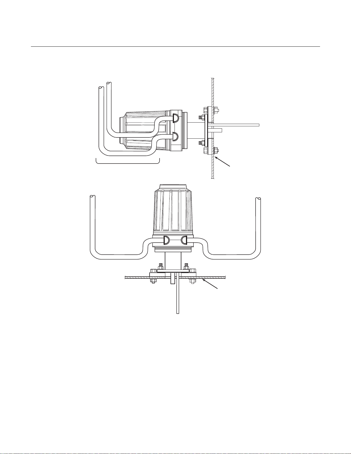
Ensure the conduits drop vertically from the OCX 8800 and the conduit
is routed below the level of the conduit ports on the housing to form a
drip loop. Drip loops minimize the possibility that moisture will damage
the electronics (Figure 2-3).
5.
Where a positive stack pressure exists at the installation site, connect all
pneumatic lines prior to installing the OCX 8800 in the stack or
ductwork.

Instruction Manual
April 2017
OCX 8800
2-3
IM-106-880CIL, Rev 1.3
NOTE
If process temperatures will exceed 392°F (200°C), use anti-seize compound
on stud threads to ease future removal of the OCX 8800.
6.
Insert sample and exhaust tubes through the opening in the mounting
flange and bolt the unit to the flange.
Uninsulated stacks or ducts may cause ambient temperatures in the electronics housing to
exceed 185°F (85°C) and damage the electronics.
7.
If insulation is removed to access the duct for OCX 8800 mounting,
make sure to replace insulation afterward.
Enclosures
The OCX 8800 enclosures are designed to meet ingress conditions of IP66.
Each enclosure cover is threaded to its base and sealed with an o-ring that
isolates the threads from external contaminants.
Each cover is secured by a clip attached to the base that engages the cover
between the ribs of the cover sidewall. The clip is held in place by an Allen
head cap screw and lockwasher mounted in a recess. Cover removal and
installation requires an Allen wrench to loosen and tighten the screw.

Instruction Manual
880CIL, Rev 1.3
April 2017
OCX 8800
4-2
Optional
In Situ Filter
8.3
(211)
Table 2. Installation/Removal
18
(457)
34
(864)
36
(914)
52
(1321)
72
(1829)
88
(2235)
108
(2743)
124
(3150)
37390008
0.06 In. Thick Gasket
ANSI
3535B18H02
DIN
3535B45H01
Table 1. Mounting
Flange
ANSI
5R10244H01
DIN
5R10244H02
Flange
6.00
7.28
Dia.
(152)
(185)
Hole
Dia.
0.75
0.71
(4) Holes
spaced on
(121)
(145)
B.C. dia
Figure 2-1. Installation, OCX 8800
NOTE
All dimensions are in inches with millimeters in parentheses.
Insulate if exposed to adverse weather or extreme temperature changes,
install a protective housing and/or insulation around the unit.
IM-106-
equally
Flange Dia.
B.C. Dia.
Hole Dia.
(19)
4.75
(18)
5.71
Allow 9 in.
(229 mm) for
Cover Removal
Dim “B”
Removal Envelope
Dim “A”
Insertion Depth
Probe Dim “A” Dim “B”
18 in.
3 ft
6 ft
9 ft
BOTTOM VIEW

Instruction Manual
IM-106-880CIL, Rev 1.3
April 2017
OCX 8800
2-5
Figure 2-2. Adapter Plate Installat ion
Instruction Manual
880CIL, Rev 1.3
April 2017
OCX 8800
6-2
Figure 2-3. Installation
Conduit Drip Loops
Duct Wall
Conduit Drip Loop
Conduit Drip Loop
Duct Wall
37020004
with Drip Loops
IM-106-

Instruction Manual
IM-106-880CIL, Rev 1.3
April 2017
OCX 8800
2-7
ELECTRICAL INSTALLATION
All wiring must conform to local and national codes. For reference, factory
wired solenoid power connections are shown in Figure 2-4.
Disconnect and lock out power before connecting the unit to the power supply. Failure to
lock out power could result in serious injury or death.
Install all protective equipment covers and safety ground leads after installation. Failure to
install covers and ground leads could result in serious injury or death.
To meet the Safety Requirements of IEC 1010 (EC requirement), and ensure safe operation
of this equipment, connection to the main electrical power supply must be made through a
circuit breaker (min 10 A) in close proximity and marked for this equipment which will
disconnect all current-carrying conductors during a fault situation. This circuit breaker
should also include a mechanically operated isolating switch. If not, then another external
means of disconnecting the supply from the equipment should be located close by. Circuit
breakers or switches must comply with a recognized standard such as IEC 947.
To maintain explosion-proof protection of the OCX 8800 in hazardous areas, all cable entry
devices and blanking elements for unused apertures must be certified flameproof, suitable
for the conditions of use and properly installed.
To maintain explosion-proof protection of the OCX88C in hazardous areas, the sensor
housing must not be mounted to any surface or flange that exceeds 200ºC (392ºF).
To maintain explosion-proof protection of the OCX88C in hazardous areas, the sample
entering the sensor housing must not exceed 200ºC (392ºF).

Instruction Manual
880CIL, Rev 1.3
April 2017
OCX 8800
8-2
IM-106-
NOTE
To maintain proper earth grounding, ensure a positive connection exists
between the sensor housing, the electronics housing, and earth. The
connecting ground wire must be 14 AWG minimum. Refer to Figure 2-4.
NOTE
Line voltage, signal, and relay wiring must be rated for at least 105ºC (221ºF).
Electrical Connections
Electrical connections, power and communications are made to the electronic
enclosure. The connections are made through two 3/4 NPT ports in the
enclosure using fittings and cables provided by the customer. Cable
installation must meet NEC, IEC and/or other applicable national or local
codes for Class I, Zone 1, IIB +H2 T3/T6 permanently mounted equipment.
Connect Line Voltage
The OCX 8800 operates on 100 to 240 VAC line voltage at 50 to 60 Hz. The
power supply requires no setup. Connect the line (L wire) to the L terminal,
and the neutral (N wire) to the N terminal on the AC power input terminal
block in the electronics housing. Connect the ground (G wire) to the ground
stud in the electronics housing as shown in Figure 2-4.
Connect 4-20 mA Signals
Connect the 4-20 mA current loop to the 4-20 mA signal output terminals in
the electronics housing as shown in Figure 2-4. Use individual shielded
twisted wire pairs. Terminate the shield at the electronics housing.
4-20 mA Signal
O
2
One 4-20 mA signal represents the O
value. Superimposed on the O
2
2
signal is the HART information accessible through a Model 275/375
Handheld Communicator or AMS software. The O
signal is at the AOUT 1
2
terminals.
COe 4-20 mA Signal
Another 4-20 mA signal at the AOUT 2 terminals represents the COe
value. HART information is not available on the COe signal.
Alarm Output Relay
Connect any customer-supplied relay input to the alarm output relay terminal.
Use shielded wire and terminate the shield at the electronics housing. The
alarm output relay terminal is a set of dry, no. 2, form C, contacts with 30 mA,
30 VDC capacity.

Instruction Manual
April 2017
OCX 8800
2-9
{
AOUT1 -
37390013
IM-106-880CIL, Rev 1.3
Figure 2-4. Line Voltage, Earth,
and 4-20 mA Connections
#1
NC
COM
NO
Alarm Output Relay
Terminal Block
COe Signal
O
Signal
2
TOP VIEW
(1/2 SIZE)
Ground Stud
Typical for Electronics and
4-20
AOUT2+
AOUT2 -
{
AOUT1+
Terminal Block
EMI Filter
Earth Ground
Sensor Housing
mA Signal Output
#1
Customer
Wiring
G
N L1
G
Terminal
Block
Ground
Stud
Signal Port
3/4 NPT
Power Port
3/4 NPT
G
External Tooth
Lockwasher
Instruction Manual
880CIL, Rev 1.3
April 2017
OCX 8800
2-10
IM-106-
PNEUMATIC INSTALLATION
Pneumatic system connections depend on whether reference air set,
calibration solenoids, and/or blowback equipment options are equipped on
your transmitter. Refer to the following paragraphs and select the option that
applies to your transmitter configuration.
Reference Air Set Option (only)
When no options or only the reference air set option is equipped, use the
following procedure to install the pneumatic system components.
1.
Refer to Figure 2-5. Connect the reference air set (regulator/filter and
pressure gage) to the instrument air inlet on the electronics housing and
to the inlet side of the dilution air flow meter.
2.
Connect the dilution air flow meter output to the dilution air inlet fitting on
the sensor housing.
3.
Install an air line between the instrument air outlet fitting on the
electronics housing and the tee fitting on the sensor housing.
.
Do not use 100% nitrogen as an O2 low gas. It is suggested that O2 low gas be between
0.4% and 2.0% O
parts per million. Failure to use proper gases will result in erroneous readings .
4.
One CO gas and two O2 gases are used to calibrate the OCX 8800:
. Do not use gases with hydrocarbon concentrations of more than 40
2
CO - 1000 ppm or up to 4%, Balance air
low gas - 0.4% , Balance N
O
2
O2 high gas - 8%, Balance N
2
2
Connect the output of the test gas sources to the inlet port of the CAL
GAS flow meter. Install an air line between the flow meter outlet port and
the CAL GAS inlet fitting on the sensor housing.
Instruction Manual
April 2017
OCX 8800
2-11
(
CO
HI O
LO O
37390011
IM-106-880CIL, Rev 1.3
Figure 2-5. Pneumatic
Installation, OCX with Reference
Air Set (without Autocalibration)
Eductor
Air In
Sensor
Housing
Reference Air In
Dilution Air In
Electronics
Housing
CAL Gas In
Dilution Air
Flow Meter
0.1 scfh
Instrument
Air Out
CAL Gas
Flow Meter
7 scfh, 20-30 psig
Recommended
2
Air Supply
Pressure Reguator/Filter
35 psig - General Purpose
45 psig - Hazardous Area
2-
Stage
Regulators
2
Instrument

Instruction Manual
880CIL, Rev 1.3
April 2017
OCX 8800
2-12
Sensor
Housing
(
CAL Gas
7 scfh,
psig
Recommended
CAL Gas In
Reference
Air In
Eductor
Air In
Dilution
Air In
Dilution Air
0.1 scfh
Electronics
Housing
Ins
Pressure Regulator/Filter
35 psig - General Purpose
45 psig - Hazardous Area
2-Stage
Regulators
Instrument
Air
Out
CAL Gas
Out
LO O
HI O
CO
37390012
Figure 2-6. Pneumatic
Installation, OCX with Reference
Air Set and Solenoids (with
Autocalibration)
Flow Meter
20-30
2
2
Reference Air Set and Solenoids Option
IM-106-
Flow Meter
Air
trument
Supply
When the reference air set and test gas solenoids are included with your
OCX 8800, use the following procedure to install the pneumatic system
components.
1.
Install the reference air set according to the instructions in Reference Air
Set Option, steps 1 through 3.
2.
Refer to Figure 2-6. Connect the O2 low gas source to the CAL GAS LO
inlet fitting on the electronics housing. Install a shutoff valve and
O
2
pressure regulator with gage in the O
3.
Connect the O2 high gas source to the CAL GAS HI O2 inlet fitting.
Install a shutoff valve and pressure regulator with gage in the O
low supply line, as shown.
2
high
2
supply line.

Instruction Manual
April 2017
OCX 8800
2-13
IM-106-880CIL, Rev 1.3
4.
Connect the CO high gas to the CAL GAS HI COe inlet fitting. Install a
shutoff valve and pressure regulator with gage in the CO high supply
line.
5.
Connect the CAL GAS outlet fitting of the electronics housing to the inlet
port of the CAL GAS flow meter. Install an air line between the flow
meter outlet port and the CAL GAS inlet fitting on the sensor housing.
Reference Air Set, Solenoids, and Blowback Option
The blowback system blows instrument air back through the blowback filter
and out the sample tube of the transmitter. This removes built up dirt and
particulate from the filter and sample line. The blowback option is normally
used in systems that have a dirty process stream.
Installing an OCX 8800 with the blowback option requires the addition of air
operated blowback valve, regulator and gage, and check valve.
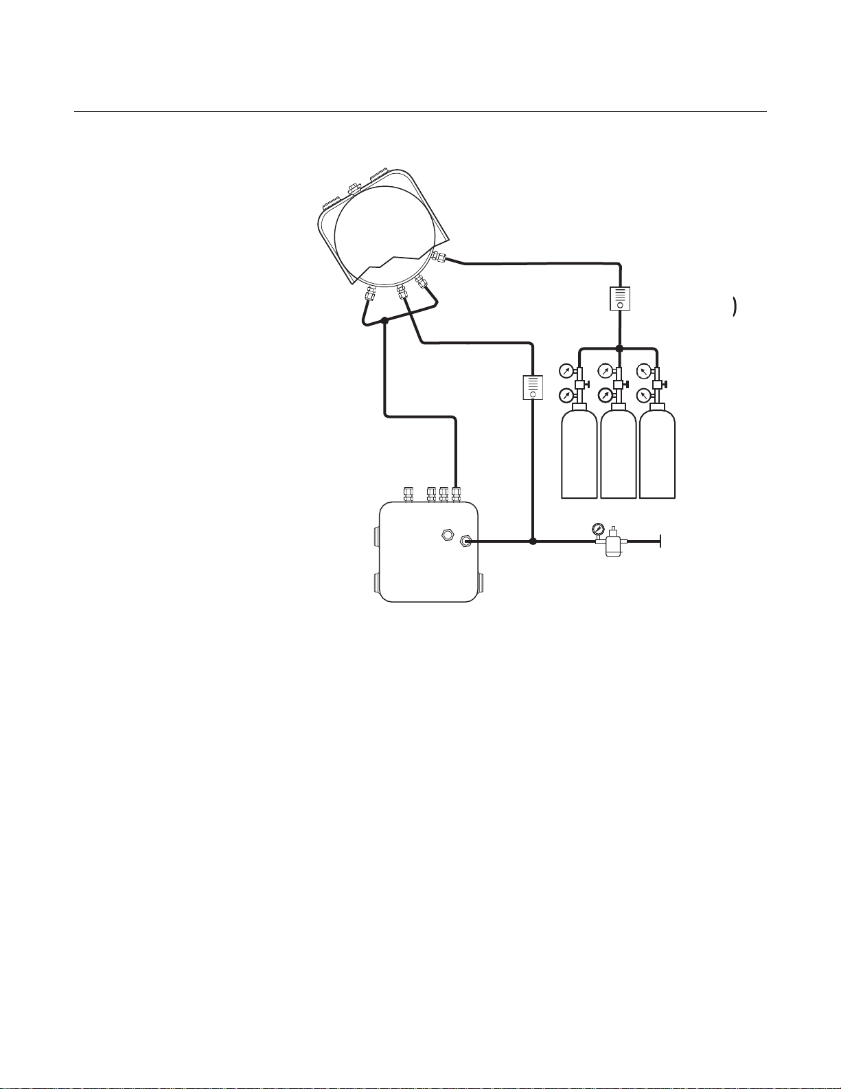
Figure 2-7 shows the piping arrangement for the OCX 8800 with the blowback
and autocalibration options. Figure 2-8 shows the piping arrangement for the
OCX 8800 with the blowback option, but without autocalibration (without test
gas solenoids).
When the reference air set, calibration gas solenoids, and blowback options
are included with your transmitter, use the following procedure to install the
pneumatic system components.
1.
Connect the calibration gas sources according to the instructions in the
previous paragraph “Reference Air Set and Solenoids Option”, steps 2
through 5.
2.
Connect a clean, dry, instrument-quality supply of air (20.95% O2) to the
35/45 psig and 55 psig pressure regulators. The inlet to the 35/45 psig
regulator accepts a 1/8" NPT fitting. The inlet to the 55 psig regulator
accepts a 1/4" NPT fitting.
3.
See the upper leg of the instrument air supply. Connect the output of the
35/45 psi regulator/filt er to one port of the normally-clo sed air-operated
solenoid valve, and to the inlet side of the dilution air flow meter.
4.
Connect the dilution air flow meter output to the DILUTION AIR inlet
fitting on the sensor housing.
5.
Install an instrument air line between the open port of the normally-open
air-operated solenoid valve and the tee fitting on the sensor housing.
6.
Connect the output of the 55 psi regulator/filter to one port of the
normally-open air-operated solenoid valve, and to the instrument air
inlet on the back of the electronics housing.
7.
Install an air line between the open port of the normally-closed
air-operated solenoid valve and the check valve inlet fitting on the
sensor housing.

Instruction Manual
880CIL, Rev 1.3
April 2017
OCX 8800
2-14
Figure 2-7. Piping Arrangement,
Blowback with Autocalibration
IM-106-

Instruction Manual
IM-106-880CIL, Rev 1.3
April 2017
OCX 8800
2-15
Figure 2-8. Piping Arrangem ent ,
Blowback without Autocalibration

Instruction Manual
IM-106-
880CIL, Rev 1.3
April 2017
OCX 8800
2-16
8.
Install an air line between the instrument air outlet fitting on the
electronics housing and the control air inlet fitting on the air-operated
solenoid valve.
9.
There are three settings that need to be specified to set up the blowback
option. These are the blowback interval, duration, and purge time.
Inter
val - Length of time between blowback events.
(60 minutes recommended.)
Duration - Length of time blowback air is activated.
(5 seconds recommended.)
Purge -
oxygen/combustibles readings are considered valid.
(Set as required by the application.)
These settings are available through HART from the DEVICE SETUP >
DETAILED SETUP > OUTPUT CONDITIONS > BLOWBACK menu.
Using the LOI, these settings are accessible from the SYSTEM >
INPUT/OUTPUT > BLOWBACK menu.
Length of time after blowback is complete before
INITIAL STARTUP Observe the following Caution and Note. Refer to Section 3: Configuration
and Startup, for OCX 8800 startup information.
Upon completing installation, make sure that the OCX 8800 is turned on and operating prior
to firing up the combustion process. Damage can result from having a cold OCX 8800
exposed to the process gases.
If ducts will be washed down during outages, make sure to power down the OCX 8800 units
and remove them from the wash area.
NOTE
During outages, and whenever possible, leave OCX 8800 units running to
prevent condensation and premature aging from thermal cycling.
Instruction Manual
IM-106-880CIL, Rev 1.3
April 2017
OCX 8800
Section 3 Configuration and Startup
Verify Installation . . . . . . . . . . . . . . . . . . . . . . . . . . . . . . . . page 3-1
Initial Power Up . . . . . . . . . . . . . . . . . . . . . . . . . . . . . . . . . . page 3-3
Set Test Gas Values . . . . . . . . . . . . . . . . . . . . . . . . . . . . . . page 3-4
OCX 8800 Reset Procedure . . . . . . . . . . . . . . . . . . . . . . . . page 3-4
Install all protective equipment covers and safety ground leads after installation. Failure to
install covers and ground leads could result in serious injury or death.
VERIFY INSTALLATION Ensure the OCX 8800 is installed correctly. Verify mechanical installation and
all electrical and pneumatic connections. Refer to Section 2, Installation.
Make sure that the OCX 8800 is turned on and operating prior to firing up the combustion
process. Damage can result from having a cold OCX 8800 exposed to the process gases.
NOTE
During outages, and whenever possible, leave all OCX 8800 units running to
prevent condensation and premature aging from thermal cycling.
Instruction Manual
880CIL, Rev 1.3
April 2017
OCX 8800
3-2
IM-106-
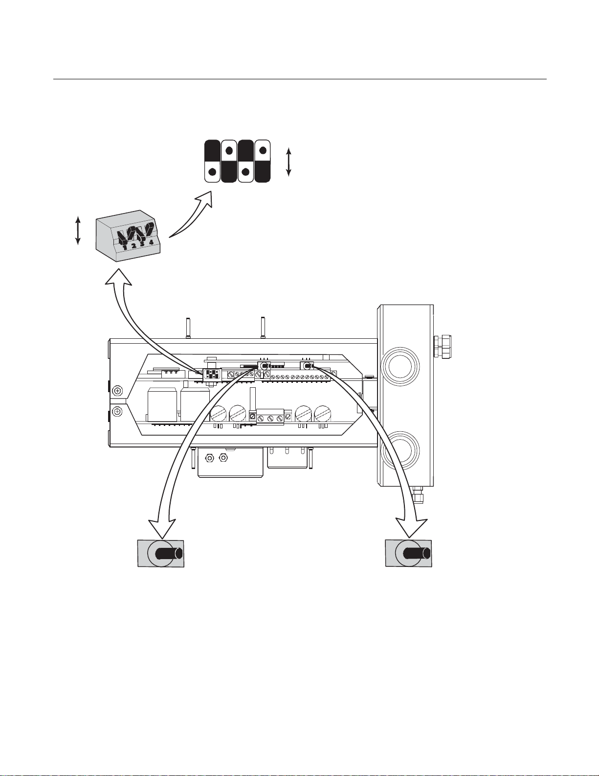
Verify Configuration
There are three switches on the microprocessor board which are user
configurable for the OCX 8800 (Figure 3-1). SW1 determines if the O
mA signal is internally or externally powered. SW2 determines if the COe 4-20
mA signal is internally or externally powered. SW3 sets the rail limits for the
and COe 4-20 mA signals and configures the sample line heater control
O
2
circuit. All switches are accessible through holes in the electronics box.
4-20
2
Remove power from the OCX 8800 before changing defaults. If defaults are changed under
power, damage to the electronics may occur.
Verify that the following switch settings are correct for your OCX 8800
installation:
SW1 The two settings are internally or externally powering the O
mA signal. The factory setting is for the O
powered.
4-20 mA signal to be internally
2
4-20
2
SW2 The two settings are internally or externally powering the COe 4-20
mA signal. The factory setting is for the COe 4-20 mA signal to be
internally powered.
SW3 The factory sets this switch as follows:
•
Position 1 determines the O2 4-20 mA signal rail limit. The settings are
high, 21.1 mA, or low, 3.5 mA. The factory setting is low, 3.5 mA.
•
Position 2 determines the COe 4-20 mA signal rail limit. The settings
are high, 21.1 mA, or low, 3.5 mA. The factory setting is high, 21.1 mA.
•
Positions 3 and 4 must be set as shown for proper software control of
the device heaters.
Instruction Manual
April 2017
OCX 8800
SW3
O
COe
37390026
IM-106-880CIL, Rev 1.3
Figure 3-1. OCX 8800 Defaults
Switch
Default Postions
Shown
Open
Closed
Internal:
COe 4-20 mA
is Internally
Powered
SW2
2
21.1 mA
3.5 mA
1 2 3
1 2 3 4
External:
COe 4-20 mA
Requires an External
Power Supply
(Default)
4
Open
Closed
O
21.1 mA/3.5 mA: O
2
Open
Closed
COe 21.1 mA/3.5 mA: COe 4-20 mA Signal
Open
Closed
Internal:
4-20 mA
O
2
is Internally
Powered
4-20 mA Signal
2
Rail Limits:
High - 21.1 mA
Low - 3.5 mA
Rail Limits:
High- 21.1 mA
Low - 3.5 mA
SW1
External:
4-20 mA
O
2
Requires an External
Power Supply
(Default)
INITIAL POWER UP Allow adequate time (approximately 60 minutes) for the heaters to begin
operation and for the OCX 8800 to reach normal operating temperature on
power up. Normal operating temperature for the O
cell is 736°C. Normal
2
operating temperature for the combustibles cell is 300°C. The normal sample
line temperature is 170°C. During this time the edu ctor air solenoid will remain
closed so no sample is pulled through the analyzer. When the OCX reaches
operating temperature the solenoid will energize, eductor air will begin to flow,
and the unit will begin normal operation.
3-3

Instruction Manual
880CIL, Rev 1.3
April 2017
OCX 8800
3-4
IM-106-
SET TEST GAS VALUES Use HART/AMS or the optional LOI to set test gas values for calibration.
Refer to Section 4, Using the LOI or Section 5, Using HART Communications
for more information.
Setting Test Gas Values with HART
1.
Use the 275/375 Field Communicator or AMS software to access the
HART menu.
2.
From the DETAILED SETUP menu, select O2 CALIB PARAMS.
3.
From O2 CALIB PARAMS, select O2 High Gas. Enter the percent O
used for the high O2 test gas.
4.
From O2 CALIB PARAMS, select Low TG. Enter the percent O2 used
for the low O
5.
From the DETAILED SETUP menu, select COe CALIB PARAMS.
6.
From COe CALIB PARAMS, select COe Test Gas. Enter the CO
concentration (ppm) used for COe test gas.
Setting Test Gas Values with the LOI
test gas.
2
2
OCX 8800 RESET PROCEDURE
1.
Use the "Z" pattern to enter the LOI menu tree.
2.
From the SYSTEM menu, select Calib Setup.
3.
From Calib Setup, select O2 High Gas %. Enter the percent O2 used
for the high O
4.
Select the down arrow and the next selection will be O2 Low Gas %.
Enter the percent O
5.
Select the down arrow several times to display COe Test Gas. Enter the
CO concentration (ppm) used for COe test gas.
Whenever you correct an equipment alarm or fault condition, the OCX 8800
will either revert to normal operation or continue to indicate an alarm status
condition. If the equipment does not revert to normal operation when a fault
condition is cleared, or if instructed to do so in Section 8, Troubleshooting,
use the following procedure to reset the OCX 8800.
OCX Reset with the LOI
1.
Use the "Z" pattern to enter the LOI menu tree. (Refer to Section 4,
Using the LOI).
2.
Select the SYSTEM submenu.
3.
From the SYSTEM submenu, select the Status submenu.
4.
From the Status submenu, select Reset Device. The OCX 8800 will
reset and the LOI will revert to the normal operation display.
test gas.
2
used for the low O2 test gas.
2
OCX Reset with HART
Remove the OCX 8800 from the process loop and recycle power.

Instruction Manual
April 2017
OCX 8800
37390027
IM-106-880CIL, Rev 1.3
Section 4 Using the LOI
Overview . . . . . . . . . . . . . . . . . . . . . . . . . . . . . . . . . . . . . . . page 4-1
Display Orientation . . . . . . . . . . . . . . . . . . . . . . . . . . . . . . . page 4-1
LOI Controls . . . . . . . . . . . . . . . . . . . . . . . . . . . . . . . . . . . . page 4-2
LOI Menu Tree . . . . . . . . . . . . . . . . . . . . . . . . . . . . . . . . . . . page 4-4
D/A Trim Procedures . . . . . . . . . . . . . . . . . . . . . . . . . . . . . page 4-8
OVERVIEW This section describes the installation and operation of the LOI module in the
OCX 8800.
DISPLAY ORIENTATION The LOI module mounts to a connector on the LOI board. The board is
installed on the end of the electronics stack in the electronics housing,
Figure 4-1. There are four mating connectors on the back of the LOI module
that allow the LOI to be oriented as desired by the user.
Figure 4-1. LOI Components
Mounting
Electronics Housing
(Cover Removed)
Electronics Stack
LOI Connector
LOI Board
LOI Module

Instruction Manual
880CIL, Rev 1.3
April 2017
OCX 8800
4-2
LK
AL
37390042
LOI CONTROLS
IM-106-
Overview The LOI, shown in Figure 4-2, utilizes a bright blue gas-fluorescent display.
Intensity is adjustable. There is an Infrared LED source and a detector for
each key. The detectors can detect a finger placed above the button through
the glass window. There is no need to open the instrument in bad weather or
in hazardous areas in order to access the electronics.
It should be noted that the Hazardous Area OCX 8800 also utilizes HART
communications, permitting access to all instrument functionality anywhere
the 4-20 mA signal terminates via a HART model 275/375 handheld
communicator.
Figure 4-2. LOI Assembly
Selection
Arrow
(Enter key)
Touch
Confirmation
LED
E
Selection
Arrow
Lockout
Notation
Display
Window
Analytical
Selection
Arrows
Status
Code
LOI Key Functions The gray (top left) key will move one level higher in the menu structure. When
entering parameter values (numbers), this key moves the cursor to the left.
The left-pointing key also doubles as an Enter key, used after the digits of a
parameter value are entered, and the cursor is moved to its left-most position.
When the Enter ke y is touched, the ne w parameter value, if accepted, will
appear in the top line of the display.
The blue (bottom left) key acts as a selector when choosing from among
several menu items. This right-pointing key also will move the cursor to the
right when entering the digits of a new parameter value.
The up and down-pointing keys are used to increment up and down when
selecting from a vertical list of menu items. These keys are also used for
incrementing values up and down for new data input.

Instruction Manual
IM-106-880CIL, Rev 1.3
April 2017
OCX 8800
4-3
1 2
E
Analytical
3 4
37390057
Figure 4-3. ‘Z’ Pattern Entry
Lockout
The LOI has a lockout feature that prevents nuisance actuation by someone
brushing against the glass window, raindrops, dirt, insects, etc. This lockout
mode is automatically established when no buttons are pushed for 30
seconds (default). This countdown to lockout is configurable.
In order to unlock the display, input a "Z" pattern (Figure 4-3). First, touch the
top left (gray) Enter key. Next, touch the top right key, followed by the bottom
left key and the bottom right key. The LK notation in the upper right corner of
the display will disappear. Touch the Enter key once more to enter into the
menu structure. Whenever a key is touched additional time to lockout is
provided, so that the lockout feature does not become a nuisance. This
additional revert time is one hour (default) and is also user configurable.
NOTE
Always clean dust and soil away from the LOI screen each time the LOI is
used. Excessive dust can prevent the LOI from entering lockout. This
condition can cause uncommanded operations to occur.
LOI Status Codes The LOI display shows a status code in the lower right hand corner of the
Table 4-1. LOI Status Codes
display. There are nine status codes to indicate the existing status of the
device during operation. The status code descriptions are shown in Table 4-1.
CODE
AL
BL
CA
CV
NM
PO
SF
ST
WU
DESCRIPTION
Alarm - The device is in a recoverable alarm state.
Blowback - A blowback cycle is active.
Calibration - A calibration cycle is active.
Calibration Verify - A calibration verify task is in progress.
Normal - The device is in a normal operating mode.
Power On - A system level initialization sequence is active. This will
continue for several seconds.
System Fault - The device is in a non-recoverable alarm condition. The unit
must be reset or power must be cycled off and on to resume operation.
Stabilize - The device heater control is stabilizing (after warm up). Sensors
are warming up to operating temperature.
Warm Up - The device heaters are ramping up to operating temperature.

Instruction Manual
IM-106-
880CIL, Rev 1.3
April 2017
OCX 8800
4-4
O2% X.XX%
Temperatures
Raw Values
Analog Outputs
O2 Temp dgC
O2 Sensor mV
CJC Temp Signal mV
37390007
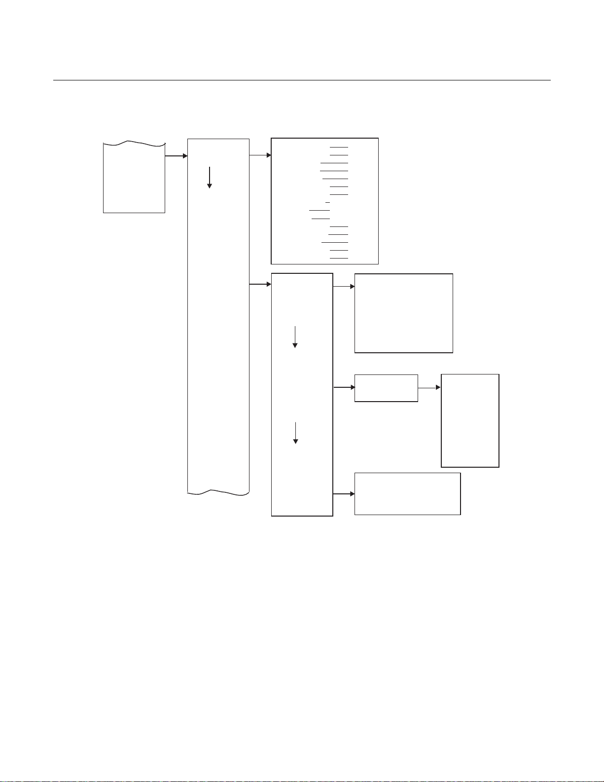
LOI MENU TREE This section consists of a menu tree for the LOI on the OCX 8800, Figure 4-4.
This menu is specific to the OCX 8800.
First Column Submenus
From the operating display (O
% and COe ppm), the left-pointing Enter key is
2
the only option to move into the first column submenus of the LOI menu tree.
The first column contains three submenus: SENSOR DATA, Figure 4-4 sheet
1 of 4, CALIBRATION, sheet 2 of 4, and SYSTEM, sheets 3 and 4 of 4. From
the operating display, SENSOR DATA is displayed when the right-pointing
key is selected. Use the up or down-pointing key to move to the other first
column submenus.
Second Column Submenus
From the first column submenus, selecting the right-pointing key moves the
display into the second column submenus. The up and down-pointing keys
allow the display to move to the second column submenus of the first column
submenu selected. The left-pointing key moves the display back to the first
column submenu.
Third and Fourth Column Submenus
From the second column submenus, selecting the right-pointing key moves
the display into the third column submenus. The third column submenu may
be another menu or a list of parameters. The up- and down-pointing keys
allow the display to move to the different parameters or menus. The third or
fourth column submenu may be a parameter list. When a parameter list is
displayed, the cursor will blink. The up- and down-pointing keys select the
value for the parameter displayed.
Figure 4-4. LOI Menu Tree
(Sheet 1 of 4)
Comb% XXX ppm
SENSOR DATA
(CONTINUED ON
SHEET 2)
O2 Temp-MAX dgC
COe Temp
COe Temp-MAX dgC
SB Temp dgC
SB Temp-MAX dgC
Board Temp dgC
Board Temp-MAX dgC
CJC Temp dgC
CJC Temp-MAX dgC
O2 Sensor R
O2 T/C mV
COe Delta V mV
COe Delta R ohm COe
Reference V mV
COe Reference R
COe T/C mV
RTD Current mA
SB T/C mV
Board Temp IC mV
O2 Output %
O2 Current mA
COe Output %
COe Current mA
dgC
ohm
ohm
%
%

Instruction Manual
IM-106-880CIL, Rev 1.3
April 2017
OCX 8800
4-5
Abort Cal
O2
Start Cal
COe
Start Cal
Both
Apply Lo O2 Gas
Cal
Control
Cal
Constants
Cal
Status
Cal
Verify
Apply Lo COe Gas
Apply Lo O2 Gas
Current
Calib
Prev
Calib
Falied
Calib
ppm/mV
ppm/mV
Bad COe Const mV
Next COe Cal
NOTE: “Hit E when ready” is displayed during
automatic calibration only (when
Calib Setup value Use Solenoids = n).
CALIBRATION
37390015
Figure 4-4. LOI Menu Tree
(Sheet 2 of 4)
(CONTINUED FROM
SHEET 1)
Start Cal
Hit E when ready
Flow O2 Lo s
% mV
Read O2 Lo s
% mV
Apply Hi O2 Gas
Hit E when ready
Flow O2 Hi s
% mV
Read O2 Hi s
% mV
Hit E when ready
Purge s
Hit E when ready
Flow COe Lo s
% mV
Read COe Lo s
% mV
Apply Hi COe Gas
Hit E when ready
Flow COe Hi s
% mV
Read COe Hi s
% mV
Hit E when ready
Purge s
(CONTINUED ON
SHEET 3)
Calib Result
Calib Step
Calib Time
Next O2 Cal
Flow High Gas
Flow Low G as
Flow COe Gas
Purge
Status
Hit E when ready
Flow O2 Lo s
% mV
Read O2 Lo s
% mV
Apply Hi O2 Gas
Hit E when ready
Flow O2 Hi s
% mV
Read O2 Hi s
% mV
O2 Slope mV/D
O2 Constant mV
O2 Sensor R ohm
COe Slope
COe Constant mV
Pre O2 Slope mV/D
Pre O2 Const mV
Pre O2 Sensor R ohm
Pre COe Slope
Pre COe Const mV
Bad O2 Slope mV/D
Bad O2 Const mV
Bad COe Slope ppm/mV
Hit E when ready
Purge s
Flow COe Hi s
Read COe Hi s
Hit E when ready
Purge s
semi-
% mV
% mV
Instruction Manual
880CIL, Rev 1.3
April 2017
OCX 8800
4-6
Analog
Alarm Relay
Blowback
Figure 4-4. LOI Menu Tree
All
Sample Ln Temp
Trigger 1 Event
O2 High Gas %
O2 Type 20-4 mA
Blow Bk Status
37390017
(Sheet 3 of 4)
(CONTINUED FROM
SHEET 2)
IM-106-
SYSTEM
Calib Setup
Input/Output
(CONTINUED ON
SHEET 4)
O2 Low Gas %
O2 Reset Vals Yes/No
O2 Out Tracks Yes/No
O2 Cal Interval Hrs O2
Next Cal Hrs
COe Test Gas %
COe Reset Vals Yes/No COe
Out Tracks Yes/No COe
Cal Interval Hrs COe
Next Cal Hrs
COe Slope Warn %
Use Solenoids Yes/No
Gas Time Seconds
Purge Time Seconds
Trim COe Out (procedure)
Trigger 2 Event
Trigger 3 Event
Blow Bk Enable Yes/No
Blow Bk Intrvl Minutes
Blow Bk Period Seconds
Blow Bk Purge Seconds
O2 Range Hi %
O2 Range Lo %
O2 AlarM Level mA
Trim O2 Out (procedure)
COe Type 20-4 mA
COe Range HI ppm
COe Range Lo ppm
COe Alarm Lvl mA
COe Temp
Sample Pr Sen
Unit Fail
Hi Elect Temp
Calib Fail
O2 Cell Bad
O2 Htr Open
O2 Cell Temp
In Calibrtn
Off

Instruction Manual
April 2017
OCX 8800
4-7
Parameters
Software
Status
Alarms
37390056
IM-106-880CIL, Rev 1.3
Figure 4-4. LOI Menu Tree
(Sheet 4 of 4)
(CONTINUED FROM
SHEET 3)
SYSTEM
O2 Slope mV/D
O2 Constant mV
O2 T90 Time seconds
COe Slope ppm/ohm
COe Constant ohm
COe T90 Time seconds
Lockout Time seconds
Revert Time minutes
O2 T90 Time seconds
Luminance %
PCDC Enable Y/N
PCNC Enable Y/N
Version
Checksum
Build Number
Build Date
Restart Count
SW Err File
SW Err Line
SW Err Number
CPLD Registers
Line Frequency
Line Voltage
PCD Counter
PCN Counter
Reset Device
Sensor Housing
Serial Number

Instruction Manual
880CIL, Rev 1.3
April 2017
OCX 8800
4-8
IM-106-
D/A TRIM PROCEDURES O
D/A trim procedure using the LOI
2
Use the following procedure to perform the O
D/A trim procedure at the LOI.
2
Refer to the LOI menu tree in Figure 4-4.
To avoid a potentially dangerous operating condition, the OCX 8800 must be removed from
the automatic combustion control loop before you start the D/A trim procedure.
1.
From the operating display use the left-pointing key to select the first
column submenu. Use the down-pointing key to select SYSTEM.
2.
From the SYSTEM menu, use the down-pointing key to select
Input/Output. Use the right-pointing k e y to s el ect t h e Analog
parameters list.
3.
Scroll down to the item Trim O2 Out. Touch the right-pointing key to
start the O
trim procedure.
2
NOTE
If you wish to exit D/A Trim with no changes, step through the procedure using
yes responses, and enter no meter readings.
4.
Remove the electronics housing cover.
5.
Refer to Figure 2-4. Connect a digital multimeter to read the milliamp
output from the O
D/A converter circuit. Connec t the p os iti ve lea d to
2
the AOUT1+ terminal and connect the negati ve lead to the AOUT1terminal. Then, touch the Enter key at the LOI.
6.
The LOI displays 4 mA........Meter. The trim program inputs the
design-equivalent signal for a 4.00 mA output. Read the O
millamp
2
output at the digital multimeter. Use the right-pointing key to select each
digit and use the up- and down-pointing keys to change the value. When
the correct value is displayed, use the Enter key to input the value.
7.
The LOI displays 20 mA........Meter. The trim program inputs the
design-equivalent signal for a 20.00 mA output. Read the O
millamp
2
output at the digital multimeter. Use the right-pointing key to select each
digit and use the up- and down-pointing keys to change the value. When
the correct value is displayed, use the Enter key to input the value.
8.
The LOI displays a Meter at 4 mA prompt. Use the right-pointing key to
select the letter yes or no. Use the up- or down-pointing key to change
the letter. Then use the Enter key to input the response. If no, the
process repeats from step 7.
9.
The LOI displays a Meter at 20 mA prompt. Use the right-pointing key
to select the letter yes or no. Use the up- or down-pointing key to
change the letter. Then use the Enter key to input the response. If no,
the process repeats from step 8.
10.
When the ropiness in steps 9 and 10 are yes, the trim procedure is
complete. Exit the LOI menu and return the control loop to automatic
control.

Instruction Manual
April 2017
OCX 8800
4-9
IM-106-880CIL, Rev 1.3
COe D/A trim procedure using the LOI
Use the following procedure to perform the COe D/A trim procedure at the
LOI. Refer to the LOI menu tree in Figure 4-4.
To avoid a potentially dangerous operating condition, the OCX 8800 must be removed from
the automatic combustion control loop before you start the D/A trim procedure.
1.
From the operating display use the left-pointing key to select the first
column submenu. Use the down-pointing key to select SYSTEM.
2.
From the SYSTEM menu, use the down-pointing key to select
Input/Output. Use the right-pointing k e y to s el ect t he Analog
parameters list.
3.
Scroll down to the item Trim COe Out. Touch the right-pointing key to
start the COe trim procedure.
NOTE
If you wish to exit D/A Trim with no changes, step through the procedure using
yes responses, and enter no meter readings.
4.
Remove the electronics housing cover.
5.
Refer to Figure 2-4. Connect a digital multimeter to read the milliamp
output from the COe D/A converter circuit. Connect the positive lead to
the AOUT2+ terminal and connect the negati ve lead to the AOUT 2terminal. Then, touch the Enter key at the LOI.
6.
The LOI displays 4 mA........Meter. The trim program inputs the
design-equivalent signal for a 4.00 mA output. Read the COe millamp
output at the digital multimeter. Use the right-pointing key to select each
digit and use the up- and down-pointing keys to change the value. When
the correct value is displayed, use the Enter key to input the value.
7.
The LOI displays 20 mA........Meter. The trim program inputs the
design-equivalent signal for a 20.00 mA output. Read the COe millamp
output at the digital multimeter. Use the right-pointing key to select each
digit and use the up- and down-pointing keys to change the value. When
the correct value is displayed, use the Enter key to input the value.
8.
The LOI displays a Meter at 4 mA prompt (question). Use the
right-pointing key to select the letter yes or no. Use the up- or
down-pointing key to change the letter. Then use the Enter key to input
the response. If no, the process repeats from step 7.
9.
The LOI displays a Meter at 20 mA prompt (question). Use the
right-pointing key to select the letter yes or no. Use the up- or
down-pointing key to change the letter. Then use the Enter key to input
the response. If no, the process repeats from step 8.
10.
When the ropiness in steps 9 and 10 are yes, the trim procedure is
complete. Exit the LOI menu and return the control loop to automatic
control.

Instruction Manual
IM-106-880CIL, Rev 1.3
April 2017
OCX 8800
4-10

Instruction Manual
April 2017
OCX 8800
IM-106-880CIL, Rev 1.3
Section 5 Using HART Communications
Overview . . . . . . . . . . . . . . . . . . . . . . . . . . . . . . . . . . . . . . . page 5-1
Field Communicator Signal Connections . . . . . . . . . . . . page 5-1
Field Communicator PC Connections . . . . . . . . . . . . . . . page 5-4
HART Menu Tree . . . . . . . . . . . . . . . . . . . . . . . . . . . . . . . . . page 5-5
D/A Trim Procedures . . . . . . . . . . . . . . . . . . . . . . . . . . . . . page 5-9
OVERVIEW The Field Communicator is a handheld communications interface device. It
provides a common communications link to all microprocessor-based
instruments that are HART compatible.
To interface with the OCX 8800, the Field Communicator requires a
termination point along the O
resistance of 250 ohms between the communicator and the power supply.
The Field Communicator accomplishes its task using a Frequency Shift
Keying (FSK) technique. With the use of FSK, high-frequency digital
communication signals are s uperimposed on the 4-20 mA oxygen output
signal. The communicator does not disturb the 4-20 mA signal since no net
energy is added to the loop. HART information is not available on the COe
output signal.
4-20 mA current loop and a minimum load
2
FIELD COMMUNICATOR
SIGNAL CONNECTIONS
The Field Communicator may be interfaced with a personal computer (PC),
providing special software has been installed. To connect the Field
Communicator may to a PC, an interface adapter is required. Refer to the
proper Field Communicator documentation in regard to the PC interface
option.
The Field Communicator can connect to the OCX 8800 oxygen analog output
signal line at any wiring termination in the O
4-20 mA current loop. There are
2
two methods of connecting the Field Communicator to the signal line. For
applications in which the signal line has a load resistance of 250 ohms or
more, refer to method 1. For applications in which the signal line load
resistance is less than 250 ohms, refer to method 2.

Instruction Manual
880CIL, Rev 1.3
April 2017
OCX 8800
5-2
Figure 5-1. Signal Line Connections,
≥ 250 Ohms Load Resistance
IM-106-
Method 1, for Load Resistance ≥ 250 Ohms
Refer to Figure 5-1 and the following steps to connect the Field
Communicator to a signal line 250 ohms or more of load resistance.
Do not make connections to the Field Communicator 's serial port, 4-20 mA signal lines, or
NiCad recharger jack in an explosive atmosphere. Explosions can result in death or serious
injury.
Using the supplied lead set, connect the Field Communicator in parallel to the
OCX 8800. Use any wiring termination points in the oxygen analog output
4-20 mA signal line.

Instruction Manual
April 2017
OCX 8800
5-3
IM-106-880CIL, Rev 1.3
Figure 5-2. Signal Line Connections,
< 250 Ohms Load Resistance
Method 2, for Load Resistance < 250 Ohms
Refer to Figure 5-2 and the following steps to connect the Field
Communicator to a signal line with less than 250 ohms load resistance.
Do not make connections to the Field Communicator's serial port, 4-20 mA signal lines, or
NiCad recharger jack in an explosive atmosphere. Explosions can result in death or serious
injury.
1.
At a convenient point, break the oxygen analog output 4-20 mA signal
line and install the optional 250 ohm load resistor.
2.
Plug the load resistor into the loop connectors (located on the rear panel
of the Field Communicator).

Instruction Manual
880CIL, Rev 1.3
April 2017
OCX 8800
5-4
IM-106-
Field Communicator PC Connections
There is an option to interface the Field Communicator with a personal
computer. Load the 375 Easy Upgrade Program ming Utility software into the
PC. Then link the Field Communicator to the PC through the IRDA Interface.
Refer to the proper Field Communicator documentation in regard to the PC
interface option.
Off-line and On-line Operations
The Field Communicator can be operated both off-line and on-line.
Off-line operations are those in which the communicator is not connected to
the OCX 8800. Off-line operations can include interfacing the Field
Communicator with a PC. (Refer to applicable documentation regarding
HART/PC applications.)
In the on-line mode, the communicator is connected to the oxygen 4-20 mA
analog output signal line. The Field Communicator is connected in parallel to
the OCX 8800 or in parallel to the 250 ohm load resistor.
The opening menu displayed on the LCD is different for on-line and off-line
operations. When powering up a disconnected (off-line) communicator, the
LCD will display the Main Menu. When powering up a connected (on-line)
communicator, the LCD will display the On-line Menu. Refer to the Field
Communicator manual for detailed menu information.

Instruction Manual
IM-106-880CIL, Rev 1.3
April 2017
OCX 8800
5-5
HART MENU TREE This section consists of a menu tree for the Field Communicator. This menu is
specific to OCX 8800 applications.
Figure 5-3. HART Menu Tree
(Sheet 1 of 4)

Instruction Manual
880CIL, Rev 1.3
April 2017
OCX 8800
5-6
Figure 5-3. HART Menu Tree (Sheet 2 of 4)
LOOP TEST
37390039
IM-106-
(CONTINUED FROM
SHEET 1 )
DIAG/SERVICE
STATUS
HW STATUS
D/A TRIM
CALIBRATE
VERIFY CALIB
Operate Mode
Status group 1
Status group 2
Status group 3
Status group 4
Status group 5
Status group 6
AO saturated
AO fixed
Model Number
Snsr Housing
CPLD REGS
Line Freq
Line Volt
PCN Counter
PCD Counter
O2 D/A Trim
COe D/A Trim
PERFORM
CAL
CAL
STATUS
CAL VALUES
PREV CAL
VALUES
FAILED CAL
VALUES
RESET CAL
CONST
Verify Calibration
Status
TimeRemain
O2
COe
Status group 1
O2 T/C Open
O2 T/C Shorted
O2 T/C Reversed
ADC Failure
O2 AO Saturated
COe AO Saturated
O2 AO Fixed
COe AO Fixed
BCSR0 BCSR3
BCSR1 BCSR4
BCSR2 BCSR5
O2 Loop Test
COe Loop Test
(procedures)
CAL METHODS
O2OutTracks
COeOutTracks
Cal Step
Cal Time
O2
COe
Cal Step
Cal Time
O2 Slope
O2 Const
O2 Snsr R
COe Slope
COe Const
O2 Slope
Prev
Prev O2 Const
Prev O2 Snsr R
Prev COe Slope
Prev COe Const
Bad O2 Slope
Bad O2 Const
Bad COe Slope
Bad COe Const
Reset O2 CalConsts
Reset COe CalConsts
Line Freq Error
O2 Htr Failure
O2 Temp Very Hi
Board Temp Hi
Status group 2
O2 Temp Low
O2 Temp Hi
O2 Snsr Open
O2 Snsr R Hi
EEPRM Chksm Fail
O2 Htr Ramp Rate
COe Htr Ramp Rate
SB Htr Ramp Rate
Status group 3
Cal Failed
Cal Warning
SB T/C Open
SB T/C Shorted
SB Temp Low
SB Temp Hi
SB Temp Very Hi
ADC Ref Error
Status group 4
RTD Current Err
COe Temp Low
COe Temp Hi
COe Temp Very Hi
COe T/C Open
COe T/C Shorted
COe T/C Reversed
SB T/C Reversed
Status group 5
COe Htr Failure
SB Htr Failure
Line Voltage Low
Line Voltage Hi
Htr Relay Failed
Output Board Failure
Status group 6
O2 Slope Error
O2 Constant Error
O2 Cal Failed
COe Slope Error
COe Constant Error
COe Cal Failed
O2 Calibration
COe Calibration
O2 and COe Calib
(CONTINUED ON
SHEET 3)
BLOWBACK
MAX TEMP
HEATER PID
BlBk State
Blowback
O2TempMax
COeTempMax
SBTempMax
BrdTempMax
CJCTempMax
O2 PID
COE
PID
SB PID
O2 Prop
O2 Int
O2 DutyCyc
O2 SetPt
O2 Temp
COe Prop
COe Int
COe DutyCyc
COe SetPt
COe Temp
SB Prop
SB Int
SB DutyCyc
SB SetPt
SB Temp
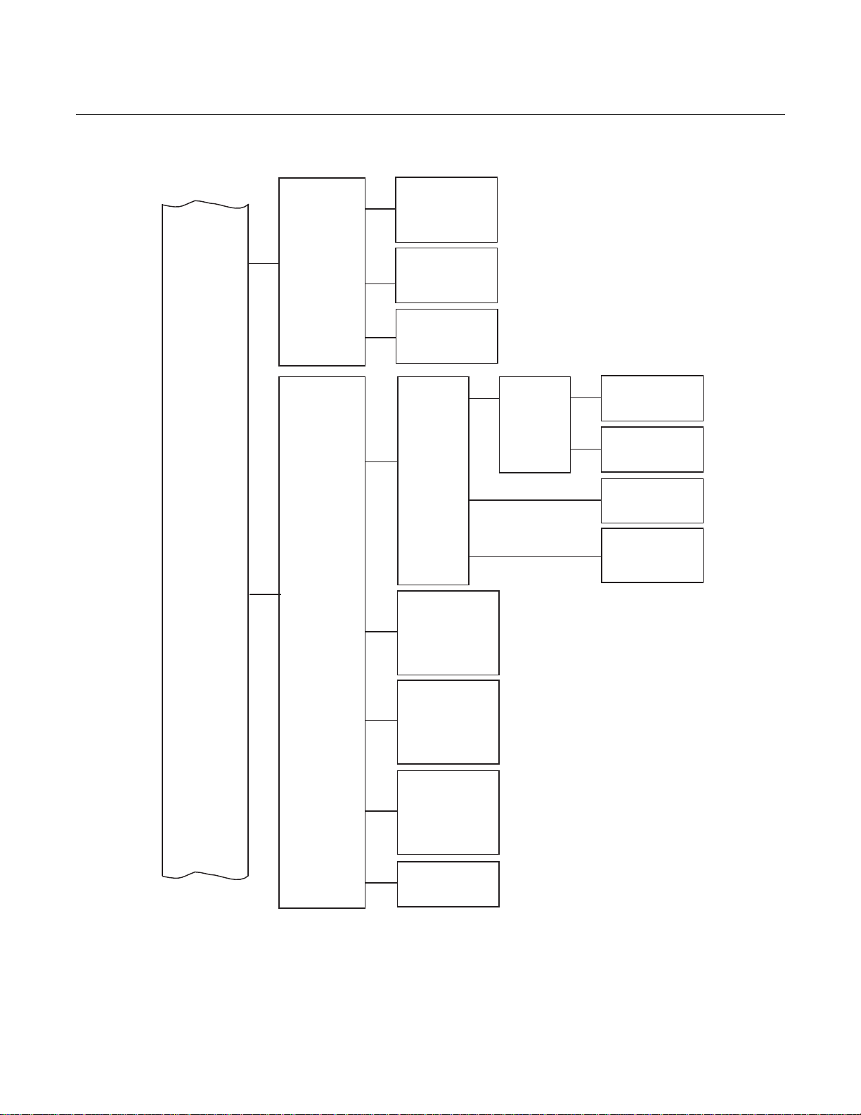
Instruction Manual
April 2017
OCX 8800
5-7
DEVICE
INFORMATION
HART
INFORMATION
S/W VERSION
INFO
Date
OUTPUT
CONDITION
O2 CALIB
PARAMS
COe CALIB
PARAMS
DEVICE
PARAMS
LOI
PARAMS
ANALOG
OUTPUT
ALARM
RELAY
BLOWBACK
O2 ANALOG
OUTPUT
COe ANALOG
OUTPUT
O2 AO Type
O2OutTracks
O2 Slope
User Intface
(CONTINUED FROM
SHEET 2)
BASIC SETUP
DETAILED
SETUP
(CONTINUED ON
SHEET 4)
37390040
IM-106-880CIL, Rev 1.3
Figure 5-3. HART Menu Tree
(Sheet 3 of 4)
Descriptor
Message
Final asmbly num
O2 Sensor s/n
COe Sensor s/n
Tag
Poll addr
Dev id
Num req preams
Fld dev rev
Version
Chksum
Bld Num
Bld Date
Restart Cntr
O2 URV
O2 LRV
O2 Alarm Level
COe AO Type
COe URV
COe LRV
COe Alarm Level
Trig 1 Event
Trig 2 Event
Trig 3 Event
Alarm State
BlBk Enabled
BlBk Intrvl
BlBk Period
BlBk PurgeTm
BlBk State
O2 High Gas
O2 Low Gas
Gas Time
Purge Time
Solenoids
O2 CalIntv
O2NxtCalTm
COeOutTracks
COe Test Gas
Gas Time
Purge Time
Solenoids
COe CalIntv
COeNxtCalTm
COe Slope Warn
O2 Const
O2 T90
COe Slope
COe Const
COe T90
PCNC Enable
PCDC Enable
Luminance
Lockout Time
Revert Time

Instruction Manual
880CIL, Rev 1.3
April 2017
OCX 8800
5-8
O2 CALIB
COE CALIB
O2NxtCalTm
COeOutTracks
REVIEW
DEVICE
INFORMATION
HART
INFORMATION
CAL INFO
DEVICE
CONFIG
OUTPUTS
CONFIG
Manufacturer
Model
Date
Descriptor
Message
Final asmbly num
O2 Sensor s/n
COe Sensor s/n
Hardware rev
Software rev
O2 Slope
O2 T90
COE DEVICE
COe Slope
CONFIG
Trig 1 Event
Trig 2 Event
Trig 3 Event
BlBk Enabled
DEVICE CONFIG
BlBk Intrvl
BlBk Period
BlBk PurgeTm
PCNC Enable
PCDC Enable
Luminance
Lockout Time
Revert Time
O2 URV
O2 LRV
COe URV
COe LRV
O2 AO Type
COe AO Type
O2 Alarm Level
COe Alarm Level
37390041
Figure 5-3. HART Menu Tree
(Sheet 4 of 4)
(CONTINUED FROM
SHEET 3)
IM-106-
Tag
Poll addr
Dev id
Num req preams
Fld dev rev
Universal rev
O2OutTracks
O2 High Gas
O2 Low Gas
Gas Time
Purge Time
Solenoids
O2 CalIntv
O2 DEVICE
CONFIG
COe Test Gas
Gas Time
Purge Time
Solenoids
COe CalIntv
COeNxtCalTm
COe Slope Warn
O2 Const
COe Const
COe T90

Instruction Manual
April 2017
OCX 8800
5-9
IM-106-880CIL, Rev 1.3
D/A TRIM PROCEDURES O
D/A trim procedure using HART
2
Use the following procedure to perform the O
D/A trim procedure using the
2
Field Communicator. Refer to the HART menu tree, Figure 5-3.
NOTE
To select a menu item, either use the up and down arrow keys to scroll to the
menu item and press t he r i ght ar r o w k e y or us e t he nu mber keypad to select
the menu item number.
To return to a preceding menu, press the left arrow key.
1.
From the DIAG/SERVICE menu, select D/A TRIM. The Field
Communicator displays O2 D/A Trim.
2.
Press the right arrow key to start the procedure. (If you wish to exit D/A
Trim with no changes, select ABORT.)
3.
The Field Communicator displays WARNING: Loop should be
removed from automatic control. Remove the OCX 8800 from any
automatic control loops to avoid a potentially dangerous operating
condition and press OK.
4.
The Field Communicator displays Connect reference meter to O2
output.
5.
Remove the electronics housing cover.
6.
Refer to Figure 2-4. Connect a digital multimeter to read the milliamp
output from the O
D/A converter circuit. Connec t the p os iti ve lea d to
2
the AOUT1+ terminal and connect the negati ve lead to the AOUT1terminal. Then, press OK at the Field Communicator.
7.
The Field Communicator displays Setting Fld dev output to 4 mA.
Press OK. Read the O
millamp output at the digital multimeter. Enter
2
the reading at the Field Communicator and press ENTER. (Select
ABORT to exit without changes).
8.
The Field Communicator displays Setting Fld dev output to 20 mA.
Press OK. Read the O
millamp output at the digital multimeter. Enter
2
the reading at the Field Communicator and press ENTER. (Select
ABORT to exit without changes).
9.
The Field Communicator displays Setting Fld dev output to 4 mA.
Press OK.
10.
The Field Communicator displays Fld dev output 4.00 mA equal to
reference meter? Using the up or down arrow, select 1 Yes or 2 No
and Press ENTER. If No, the process repeats from step 6.
11.
The Field Communicator displays Setting Fld dev output to 20 mA.
Press OK.
12.
The Field Communicator displays Fld dev output 20.00 mA equal to
reference meter? Using the up or down arrow, select 1 Yes or 2 No
and Press ENTER. If No, the process repeats from step 7.
13.
The Field Communicator displays NOTE: Loop may be returned to
automatic control.

Instruction Manual
880CIL, Rev 1.3
April 2017
OCX 8800
5-10
IM-106-
COe D/A trim procedure using HART
Use the following procedure to perform the COe D/A trim procedure using the
Field Communicator. Refer to the HART menu tree, Figure 5-3.
NOTE
To select a menu item, either use the up and down arrow keys to scroll to the
menu item and press t he r i ght ar r o w k e y or us e t he nu mber keypad to select
the menu item number.
To return to a preceding menu, press the left arrow key.
1.
From the DIAG/SERVICE menu, select D/A TRIM. The Field
Communicator displays O2 D/A Trim. Press the up or down arrow to
select COe D/A Trim.
2.
Press the right arrow key to start the procedure. (If you wish to exit D/A
Trim with no changes, select ABORT.)
3.
The Field Communicator displays WARNING: Loop should be
removed from automatic control. Remove the OCX 8800 from any
automatic control loops to avoid a potentially dangerous operating
condition and press OK.
4.
The Field Communicator displays Connect reference meter to
Combustibles output.
5.
Remove the electronics housing cover.
6.
Refer to Figure 2-4. Connect a digital multimeter to read the milliamp
output from the COe D/A converter circuit. Connect the positive lead to
the AOUT2+ terminal and connect the negati ve lead to the AOUT 2terminal. Then, press OK at the HART communicator.
7.
The Field Communicator displays Setting Fld dev output to 4 mA.
Press OK. Read the COe millamp output at the digital multimeter. Enter
the reading at the Field Communicator and press ENTER. (Select
ABORT to exit without changes).
8.
The Field Communicator displays Setting Fld dev output to 20 mA.
Press OK. Read the COe millamp output at the digital multimeter. Enter
the reading at the Field Communicator and press ENTER. (Select
ABORT to exit without changes).
9.
The Field Communicator displays Setting Fld dev output to 4 mA.
Press OK.
10.
The Field Communicator displays Fld dev output 4.00 mA equal to
reference meter? Using the up or down arrow, select 1 Yes or 2 No
and Press ENTER. If No, the process repeats from step 6.
11.
The Field Communicator displays Setting Fld dev output to 20 mA.
Press OK.
12.
The Field Communicator displays Fld dev output 20.00 mA equal to
reference meter? Using the up or down arrow, select 1 Yes or 2 No
and Press ENTER. If No, the process repeats from step 7.
13.
The Field Communicator displays NOTE: Loop may be returned to
automatic control.

Instruction Manual
April 2017
OCX 8800
IM-106-880CIL, Rev 1.3
Section 6 Calibration
Overview . . . . . . . . . . . . . . . . . . . . . . . . . . . . . . . . . . . . . . . page 6-1
Fully Automatic Calibration . . . . . . . . . . . . . . . . . . . . . . . . page 6-1
Operator - Initiated Autocalibration . . . . . . . . . . . . . . . . . page 6-4
Manual Calibration . . . . . . . . . . . . . . . . . . . . . . . . . . . . . . . page 6-4
OVERVIEW During a calibration, two calibration gases with known O
one calibration gas with a known COe concentration are applied to the OCX
8800. Slope and constant values are calculated to determine if the OCX 8800
is correctly measuring net concentrations of O
industrial process.
Before calibrating the OCX 8800, verify that the calibration gas parameters
are correct by setting the test gas values used when calibrating the unit. Refer
to Section 3, Configuration and Startup.
There are three calibration methods available to the OCX 8800; automatic,
operator-initiated automatic, and manual. Calibration commands and menus
can be accessed by HART/AMS or by the LOI.
and combustibles in the
2
concentrations and
2
FULLY AUTOMATIC
CALIBRATION
If the OCX 8800 is equipped with calibration solenoids, the unit can be
programmed to automatically calibrate without any operator action. Refer to
the following paragraphs for using the LOI or HART/AMS to set up the OCX
8800 for fully automatic calibration.
Autocalibration Setup using the LOI
Use the following procedure to set up the OCX 8800 for automatic calibration.
If necessary, use the LOI menu tree in Figure 4-4 for reference. The unit must
be equipped with calibration solenoids to use automatic calibration.
NOTE
Automatic calibration is only available on units equipped with calibration
solenoids.
1.
From the operating display use the right-pointing key to select SYSTEM
first column submenu.
2.
From the SYSTEM first column submenu, use the right-pointing key to
select the Calib Setup second column submenu.
3.
From the Calib Setup second column submenu, use the right-pointing
key to select the third column parameter list.

Instruction Manual
880CIL, Rev 1.3
April 2017
OCX 8800
6-2
IM-106-
4.
Scroll down to the last item Use Solenoids. If the unit is equipped with
calibration solenoids and timed automatic calibration is desired, select
Yes.
5.
Use the up-pointing key to select the item O2 Out Tracks. Select Yes or
No to determine if updates to the O
6.
Use the down-pointing key to select the item COe Out Tracks. Select
Yes or No to define if updates to the COe lock value will take place.
7.
Use the down-pointing key to select the item O2 Cal Interval. Enter the
amount of time in days and hours that is desired between automatic
calibrations.
8.
Use the down-pointing key to select the next item O2 Next Cal. Enter
the amount of time in hours until the next automatic calibration. Select
the left-pointing key three times to move back to the LOI operating
display.
Autocalibration Setup using HART
NOTE
Automatic calibration is only available on units equipped with calibration
solenoids.
Use the following procedure to specify a time interval (in hours) at which the
OCX 8800 will automatically calibrate.
lock value will take place.
2
1.
From the DEVICE SETUP screen, select DETAILED SETUP.
2.
From the DETAILED SETUP screen, select O2 CALIB PARAMS or
COE CALIB PARAMS.
3.
If the unit is equipped with calibration solenoids and timed automatic
calibrations are desired, select Solenoids, then select Yes. Select No to
disable the calibration solenoids.

Instruction Manual
April 2017
OCX 8800
6-3
IM-106-880CIL, Rev 1.3
4.
Select O2 CalIntrvl (O2 calibration interval) and enter the desired time
in hours between automatic O
calibrations. Select COE Callintrvl and
2
enter the desired time between automatic COe calibrations. To disable
automatic calibration for O
and COe, enter 0 for both CalIntrvl
2
parameters.
5.
If desired, the O2NxtCalTm and the COeNxtCalTm (next calibration
time) parameters can be changed to synchronize a calibration at a
specific day or time.
When setting automatic calibration times, CalIntrvl and NxtCalTm should be set so that O
and COe are NOT calibrated simultaneously.
2
NOTE
To select a menu item, either use the up and down arrow keys to scroll to the
menu item and press t he r i ght ar r o w k e y or us e t he nu mber keypad to select
the menu item number.
To return to a preceding menu, press the left arrow key.
6.
Select O2 CalIntrvl (O2 calibration interval) and enter the desired time
in hours between automatic O
calibrations. Select COE Callintrvl and
2
enter the desired time between automatic COe calibrations. To disable
automatic calibration for O
and COe, enter 0 for both CalIntrvl
2
parameters.

Instruction Manual
880CIL, Rev 1.3
April 2017
OCX 8800
6-4
IM-106-
OPERATOR - INITIATED AUTOCALIBRATION
An operator can initiate an automatic calibration at any time provided that the
unit is equipped with calibration solenoids.
Autocalibration using the LOI
To initiate a calibration using the LOI, perform the following steps on the LOI
menu tree. Refer to Section 4, Using the LOI, for the LOI menu tree.
1.
From the CALIBRATION menu, use the right-pointing arrow to select
the Cal Control menu.
2.
Select Start Cal-O2, Start Cal COe, or Start Cal Both to start the
calibration. Select Cal Verify to access the calibration window.
3.
At the prompt, use the right-pointing arrow to initia te automatic
calibration.
Autocalibration using HART
To initiate an automatic calibration using HART/AMS, perform the following
steps on the HART menu tree. Refer to Section 5, Using HART
Communications, for the HART menu tree.
1.
Select DIAG/SERVICE from DEVICE SETUP menu.
2.
Select CALIBRATION from the DIAG/SERVICE menu.
3.
Select PERFORM CAL from the CALIBRATION menu.
4.
Select CAL METHODS from the PERFORM CAL menu.
5.
From the CAL METHODS menu, select the type of calibration desired:
O2 Calibration, COe Calibration, or O2 and COe Calibration.
MANUAL CALIBRATION If a unit is not equipped with calibration solenoids, a calibration must be
performed by an operator following prompts from the unit. Refer to the
following paragraphs for manual calibration.
Manual Calibration using the LOI
Use the following procedure to perform a manual calibration with the LOI. If
necessary, refer to the menu tree in Section 4, Using the LOI. Once the
manual calibration procedure is initiated at the LOI, a series of prompts will
appear giving instructions to the operator.
1.
Use the right-pointing key to select the CALIBRATION first column
submenu.
2.
From the CALIBRATION submenu use the right-pointing key to select
the Cal Control second column submenu.
3.
From the Cal Control submenu use the right-pointing key to select the
third column Start Cal O2 option.
4.
Remain at the Start Cal O2 option or use the down-pointing key to
select the Start Cal COe option or Start Cal Both option. (The following
sequence applies when Start Cal Both is selected.)
5.
Use the right-pointing key to start the calibration. Turn on the low O2 test
gas, when prompted by the Flow Low Gas message.
6.
Press the right-pointing key when the low O2 test gas is applied. The
calibration data changes as the calibration proceeds.

Instruction Manual
April 2017
OCX 8800
6-5
IM-106-880CIL, Rev 1.3
7.
Press the right-pointing k e y when the lo w O2 reading is stable. T urn off
the low O
test gas and turn on the high O2 test gas as prompted by the
2
Flow High Gas message.
8.
Press the right-pointing key when the high O2 test gas is applied. The
calibration data changes as the calibration proceeds.
9.
Press the right-pointing key when the high O2 reading is stable. Turn off
the high O
test gas. Press the right-pointing key to start the high O2 gas
2
purge.
10.
When the purge period expires, the LOI display reverts to the normal
operation display. If the calibration failed, the display will indicate an
alarm condition.
11.
Press the right-pointing key to start combustibles calibration. Turn on
the CO test gas when prompted.
12.
Press the right-pointing key when the CO test gas is applied. The
calibration data changes as the calibration proceeds.
13.
Press the right-pointing key when the CO reading is stable.
14.
Turn off the CO test gas and press the right-pointing key to start the CO
gas purge.
15.
When the purge period expires, the LOI display reverts to the normal
operation display. If the calibration failed, the display will indicate an
alarm condition.
Manual O
To perform a manual O
Calibration using HART
2
calibration using the Field Communicator or AMS,
2
use the following procedure. If necessary, refer to Section 5, Using HART
Communications, for the HART menu tree.
NOTE
To select a menu item, either use the up and down arrow keys to scroll to the
menu item and press t he r i ght ar r o w k e y or us e t he nu mber keypad to select
the menu item number.
To return to a preceding menu, press the left arrow key.
1.
From the DIAG/SERVICE menu, select CALIBRATION. From the
CALIBRATION menu, select PERFORM CAL.
2.
From the PERFORM CAL menu, select CAL METHODS. Sele c t O2
CALIBRATION to start O
3.
In the first O2 Calibration screen, a Loop should be removed from
calibration.
2
automatic control warning appears. Remove the OCX 8800 from any
automatic control loops to avoid a potentially dangerous operating
condition and press OK.
4.
The main Calibration screen should look like the following. Press OK to
continue.
OCX: TAG NAME
STATUS: Idle
TIME REMAIN: 0s
O2: 0.4 %, 85.95mV
OK/NEXT to Select
ABORT/CANCEL to Exit

Instruction Manual
880CIL, Rev 1.3
April 2017
OCX 8800
6-6
IM-106-
5.
From the SELECT ACTION screen, select START/NEXT CALSTEP to
continue calibration, select ABORT CAL to abort calibration or EXIT
CAL to exit calibration. Select one item from the list and press ENTER.
OCX: TAG NAME SELECT ACTION
1.
START/NEXT CALSTEP
2.
ABORT CAL
3.
EXIT CAL
6.
When the Calibration Status is at the AppO2Low step, switch on O
Low Gas. Verify the O2 concentration measured matches the O2 LOW
GAS parameter in the Setup. Press OK when ready.
7.
Select Start/Next Cal Step to start applying the O2 Low Gas. The time
to apply the test gas is specified by the Gas Time.
8.
The Calibration Status should be automatically changed to FlowO2Low
and then ReadO2Low for a period of time. During this period, if an
attempt is made to go to the next calibration step by pressing OK and
selecting Start/Next Cal Step, you will be prompted with Operator step
command is not accepted at this time. The Next Cal Step command
is not accepted at this time.
9.
When ready, Calibration St atus wil l stop at the AppO2Hi. Switch off the
O
Low Gas and switch on the O2 High Gas. Verify the O2 concentration
2
measured matches the O2 HIGH GAS parameter in the Setup. Press
OK when ready.
10.
Select Start/Next Cal Step to start applying the O2 High Gas. The time
to apply the test gas is specified by the Gas Time.
11.
The Calibration Status should be automatically changed to FlowO2Hi
and then ReadO2Hi for a period of time. During this period, if an attempt
is made to go the next calibration step by pressing OK and selecting
Start/Next Cal Step, you will be prompted with Operator step
command is not accepted at this time. The Next Cal Step command
is not accepted at this time.
12.
When ready, Calibration Status will stop at STOP GAS. Switch off the
O
High Gas. Press OK when ready. Select Start/Next Cal Step to start
2
purging gas. The time to purge gas is specified by the Purge Time.
13.
When the Purge step is complete, the Calibration Status will be at IDLE
if the calibration is successful or CAL RECOMMENDED if the
calibration has failed. A Calibration Failed alarm will be set if the
calibration has failed.
14.
When calibration is complete. Select Exit Cal to exit the calibration
method.
2

Instruction Manual
April 2017
OCX 8800
6-7
IM-106-880CIL, Rev 1.3
Manual COe Calibration using HART
To perform a manual COe calibration using the Field Communicator or AMS,
use the following procedure. If necessary, refer to Section 5, Using HART
Communications, for the HART menu tree.
NOTE
To select a menu item, either use the up and down arrow keys to scroll to the
menu item and press the right arro w k e y or use the number k e ypad to se lec t
the menu item number.
To return to a preceding menu, press the left arrow key.
1.
From the DIAG/SERVICE menu, select CALIBRATION. From the
CALIBRATION menu, select PERFORM CAL.
2.
From the PERFORM CAL menu, select CAL METHODS. Sele c t COe
CALIBRATION to start COe calibration.
3.
In the first COe Calibration screen, a Loop should be removed from
automatic control warning appears. Remove the OCX 8800 from any
automatic control loops to avoid a potentially dangerous operating
condition and press OK.
4.
The main Calibration screen should look like the following. Press OK to
continue.
OCX: TAG NAME
STATUS: Idle
TIME REMAIN: 0s
COe: 0.20 ppm, 0.00 mV
OK/NEXT to Select
ABORT/CANCEL to Exit
5.
From the SELECT ACTION screen, select START/NEXT CALSTEP to
continue calibration, select ABORT CAL to abort calibration or EXIT
CAL to exit calibration. Select one item from the list and press ENTER.
OCX: TAG NAME SELECT ACTION
1.
START/NEXT CALSTEP
2.
ABORT CAL
3.
EXIT CAL
6.
The unit samples reference air as the COe Low Gas. The Calibration
Status should automatically change to ReadCOLow for a period of time.
During this period, if an attempt is made to go to the next calibration
step by pressing OK and selecting Start/Next Cal Step, you will be
prompted with Operator step command is not accepted at this time.
The Next Cal Step command is not accepted at this time.
7.
When ready, Calibration Status will stop at the AppCOeHi. Switch on
the COe High Gas. Verify the COe concentration measured matches the
COe HIGH GAS parameter in the Setup. Press OK when ready.
8.
Select Start/Next Cal Step to start applying the COe High Gas. The
time to apply the test gas is specified by the Gas Time.

Instruction Manual
880CIL, Rev 1.3
April 2017
OCX 8800
6-8
IM-106-
9.
The Calibration Status should be automatically changed to FlowCOeHi
and then ReadCOeHi for a period of time. During this period, if an
attempt is made to go the next calibration step by pressing OK and
selecting Start/Next Cal Step, you will be prompted with Operator step
command is not accepted at this time. The Next Cal Step command
is not accepted at this time.
10.
When ready, Calibration Status will stop at STOP GAS. Switch off the
COe High Gas. Press OK when ready. Select Start/Next Cal Step to
start purging gas. The time to purge gas is specified by the Purge Time.
11.
When the Purge step is complete, the Calibration Status will be at IDLE
if the calibration is successful or CAL RECOMMENDED if the
calibration has failed. A Calibration Failed alarm will be set if the
calibration has failed.
12.
When calibration is complete. Select Exit Cal to exit the calibration
method.
Manual O
To perform a manual O
and COe Calibration using HART
2
and COe calibration using the Field Communicator or
2
AMS, use the following procedure. If necessary, refer to Section 5, Using
HART Communications, for the HART menu tree.
NOTE
To select a menu item, either use the up and down arrow keys to scroll to the
menu item and press t he r i ght ar r o w k e y or us e t he nu mber keypad to select
the menu item number.
To return to a preceding menu, press the left arrow key.
1.
From the DIAG/SERVICE menu, select CALIBRATION. From the
CALIBRATION menu, select PERFORM CAL.
2.
From the PERFORM CAL menu, select CAL METHODS. Select 02 &
COe CALIBRATION to start O
3.
In the first Calibration screen, a Loop should be removed from
and COe calibration.
2
automatic control warning appears. Remove the OCX 8800 from any
automatic control loops to avoid a potentially dangerous operating
condition and press OK.
4.
The main Calibration screen should look like the following. Press OK to
continue.
OCX: TAG NAME
STATUS: Idle
TIME REMAIN: 0s
O2: 0.4 %, 85.95mV
COe: 0.20 ppm, 0.00 mV
OK/NEXT to Select
ABORT/CANCEL to Exit

Instruction Manual
April 2017
OCX 8800
6-9
IM-106-880CIL, Rev 1.3
5.
From the SELECT ACTION screen, select START/NEXT CALSTEP to
continue calibration, select ABORT CAL to abort calibration or EXIT
CAL to exit calibration method. Select one from the list and press
ENTER.
OCX: TAG NAME SELECT ACTION
1.
START/NEXT CALSTEP
2.
ABORT CAL
3.
EXIT CAL
6.
When the Calibration Status is at the AppO2Low step, switch on O
Low Gas. Verify the O2 concentration measured matches the O2 LOW
GAS parameter in Setup. Press OK when ready.
7.
Select Start/Next Cal Step to start applying the O2 Low Gas. The time
to apply the test gas is specified by the Gas Time.
8.
The Calibration Status should automatically change to FIowO2Low and
then ReadO2Low for a period of time. During this period, if an attempt
is made to go to the next calibration step by pressing OK and selecting
Start/Next Cal Step, you will be prompted with Operator step
command is not accepted at this time. The Next Cal Step command
is not accepted at this time.
9.
When ready, Calibration Status will stop at AppO2Hi. Switch off the O
Low Gas and switch on the O2 High Gas. Verify the O2 concentration
measured matches the O2 HIGH GAS parameter in Setup. Press OK
when ready.
10.
Select Start/Next Cal Step to apply the O2 High Gas. The time to apply
the test gas is specified by the Gas Time.
11.
The Calibration Status should automatically change to FlowO2Hi, then
ReadO2Hi, and then ReadCOeLo for a period of time. During this
period, if an attempt is made to go the next calibration step by pressing
OK and selecting Start/Next Cal Step, you will be prompted with
Operator step command is not accepted at this time. The Next Cal
Step command is not accepted at this time.
12.
When ready, Calibration Status will stop at AppCOeHi. Switch off the O
High Gas and switch on the COe Gas. Verify the COe concentration
measured matches the COe TEST GAS parameter in the Setup. Press
OK when ready.
13.
Select Start/Next Cal Step to start applying the COe Gas. The time to
apply the test gas is specified by the Gas Time.
14.
The Calibration Status should automatically change to FlowCOeHi and
then ReadCOeHi for a period of time. During this period, if an attempt is
made to go the next calibration step by pressing OK and selecting
Start/Next Cal Step, you will be prompted with Operator step
command is not accepted at this time. The Next Cal Step command
is not accepted at this time.
15.
When ready, Calibration Status will stop at STOP GAS. Switch off the
COe gas. Press OK when ready. Select Start/Next Cal Step to start
purging gas. The time to purge gas is specified by Purge Time.
2
2
2

Instruction Manual
880CIL, Rev 1.3
April 2017
OCX 8800
6-10
IM-106-

Instruction Manual
April 2017
OCX 8800
IM-106-880CIL, Rev 1.3
Section 7 Maintenance and Service
Overview . . . . . . . . . . . . . . . . . . . . . . . . . . . . . . . . . . . . . . . page 7-1
OCX 8800 Removal and Installation . . . . . . . . . . . . . . . . . page 7-1
Repair Sensor Housing . . . . . . . . . . . . . . . . . . . . . . . . . . . page 7-5
Repair Electronics Housing . . . . . . . . . . . . . . . . . . . . . . . . page 7-25
Replace Tube Fittings . . . . . . . . . . . . . . . . . . . . . . . . . . . . . page 7-31
OVERVIEW This section contains the procedures to maintain and service the OCX 8800.
Install all protective equipment covers and safety ground leads after equipment repair or
service. Failure to install covers and ground leads could result in serious i nj ury or death.
OCX 8800 REMOVAL
AND INSTALLATION
It is recommended that the OCX 8800 be removed from the stack for all service activities.
The unit should be allowed to cool and be taken to a clean work area. Failure to comply may
cause severe burns.
Disconnect and lock out power before working on any electrical components. There may be
voltage up to 264 VAC.
Observe housing classification guidelines pri or to removi ng cover. Failure to observe
classification guidelines may result in serious injury or death.
Use the following procedures to remove or install the OCX 8800.

Instruction Manual
880CIL, Rev 1.3
April 2017
OCX 8800
7-2
37390043
IM-106-
OCX with
Integral Electronics
Figure 7-1. OCX with
Integral Electronics
Remove OCX 8800
1.
Turn off power to the system.
2.
Shut off the test gases at the cylinders and shut off the instrument air.
3.
Disconnect the test gas and instrument air lines from the electronics
housing, Figure 7-1.
Stack
Sensor
Housing
Electronics
Housing
Adapter
Plate
Duct
High O2 Test Gas
Low O
CO Test Gas
O
and COe
2
4-20 mA Outputs
(2 Twisted Pairs)
AC Power Input
Instrument Air
(Reference Gas)
Test Gas
2
Explosion hazard! Before removing cover from sensor or electronics housing, allow at least
45 minutes to pass after power is disconnected. Failure to allow adequate time for all
internal electrical charges to dissipate can result in serious injury or death.
4.
Remove the cover from the electronics housing to expose the
electronics housing terminal blocks, Figure 7-2.
5.
Disconnect and remove the power leads from the AC power input
terminal block and remove the ground lead from the ground stud.
6.
Disconnect and remove the O2 and COe signal leads from the 4-20 mA
signal output terminal block.
7.
If used, disconnect and remove the external relay leads from the alarm
output relay terminal block.
8.
Disconnect and remove customer power and signal wire conduits and
wiring from the electronics housing.
9.
Remove insulation to access the sensor housing mounting bolts. Unbolt
the OCX 8800 from the stack and take it to a clean work area.
10.
Allow the unit to cool to a comfortable working temperature.
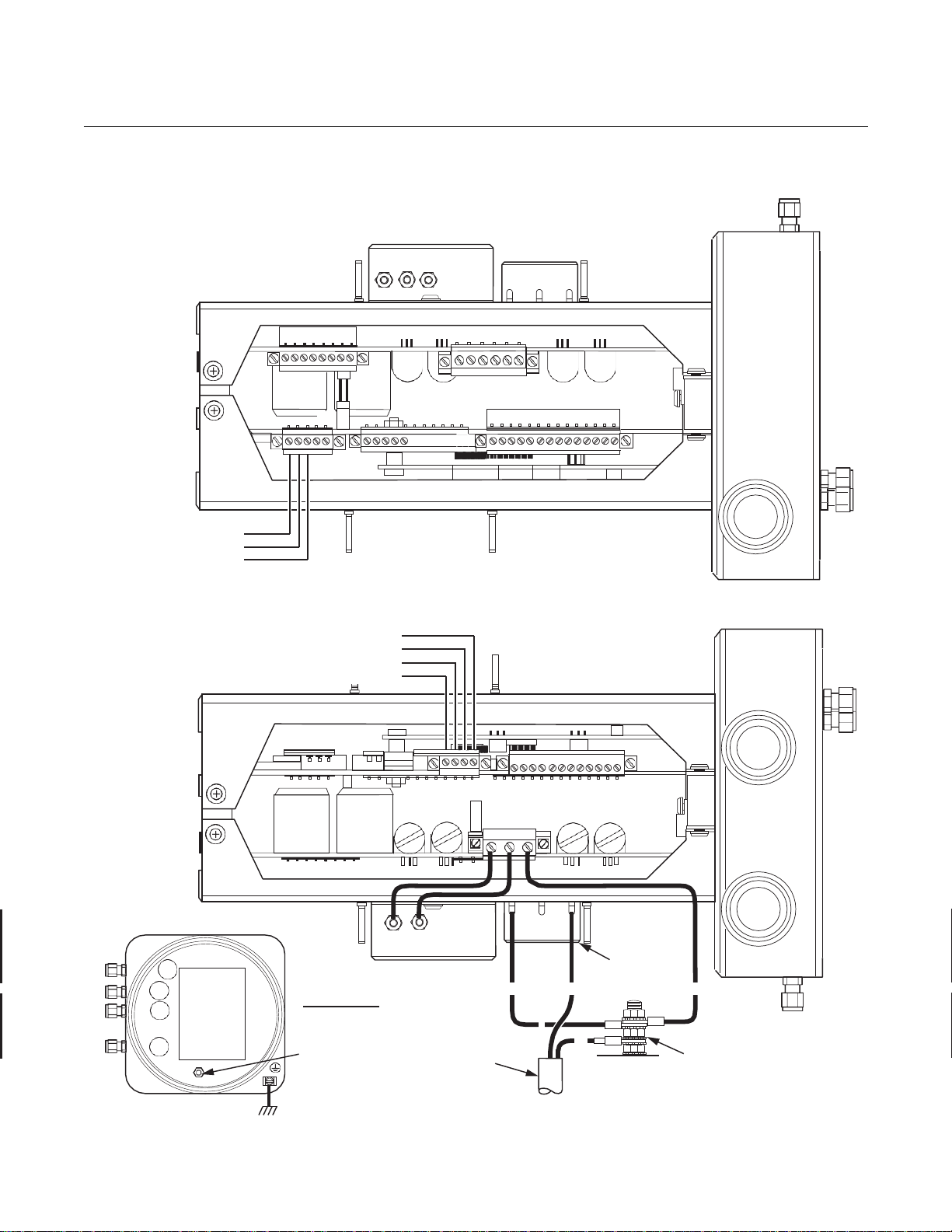
Instruction Manual
April 2017
OCX 8800
7-3
{
AOUT1 -
37390013
IM-106-880CIL, Rev 1.3
Figure 7-2. Electronics Housing
Terminal Blocks
NC
COM
NO
Alarm Output Relay
Terminal Block
#1
4-20 mA Signal Output
Terminal Block
COe Signal
O
Signal
2
AOUT2+
AOUT2 -
{
AOUT1+
EMI Filter
TOP VIEW
(1/2 SIZE)
Ground Stud
Earth Ground
Typical for Electronics and
Sensor Housing
#1
Customer
Wiring
Signal Port
3/4 NPT
Terminal
Block
G
Power Port
3/4 NPT
G
N L1
G
Ground
Stud
External Tooth
Lockwasher

Instruction Manual
880CIL, Rev 1.3
April 2017
OCX 8800
7-4
IM-106-
Install OCX 8800
Observe the following cautions when installing the OCX 8800 in a hot process
stack. If the process is shut down and cooled, the transmitter can be installed
in the stack prior to connecting the pneumatics and wiring.
Before installing the OCX 8800 into a hot stack or ductwork, make sure that the OCX 8800
is turned on and at normal operating temperature. Exposing a cold OCX transmitter to hot
process gases can cause permanent damage to the equipment.
Whenever a positive stack pressure exists at the installation site, be sure to connect all
pneumatic lines prior to installing the OCX 8800 in the stack or ductwork. Failure to connect
the pneumatic lines can allow the flow of contaminants into the OCX 8800 ports.
1.
Connect the test gas lines and the instrument air lines to the electronics
housing.
2.
Remove the electronics housing cover.
3.
Install customer power and signal conduits and wiring at the electronics
housing.
4.
If used, connect external relay leads to the alarm output relay terminal
block, Figure 7-2.
5.
Connect the O2 and COe signal leads to the 4-20 mA signal output
terminal block.
6.
Connect the line (L1 wire) to the L1 terminal, and the neutral (N wire) to
the N terminal on the AC power input terminal block.
7.
Connect the ground lead to the ground stud. Secure the connection with
two nuts. Attach a separate ground lead (G wire) from the ground stud
to the G terminal on the power input terminal block.
8.
Install the cover on the electronics housing.
9.
Restore power to the system. Allow OCX to reach normal operating
temperature before installing in a hot process stack.
10.
Bolt the OCX 8800 to the stack and install insulation. Refer to Figure 7-1
and make sure all test gas lines and electrical connections are
complete.
11.
Turn on the test gasses at the cylinders and open the instrument air
supply valve.

Instruction Manual
April 2017
OCX 8800
7-5
IM-106-880CIL, Rev 1.3
REPAIR SENSOR HOUSING
Sensor Housing
Disassembly
Use the following procedures to remove damaged components from the OCX
8800 sensor housing and to install new replacement parts. Disassemble the
unit only as needed to replace damaged components. Use the assembly
procedures that apply to install replacement parts and reassemble the unit.
Remove Cover and Terminals Insulator
1.
Loosen screw (1, Figure 7-3) and slide locking clip (2) away from cover.
Retighten screw (1).
2.
With two hands or strap wrench, turn cover (3) counterclockwise to
loosen. Unthread and remove cover.
3.
Inspect cover o-ring (4) for wear or damage. Replace cover o-ring if
damaged.
4.
Unsnap terminal marking plates (5) and remove terminal insulator (6).

Instruction Manual
880CIL, Rev 1.3
April 2017
OCX 8800
7-6
Figure 7-3. Removal of O2 Cell
and Heater Strut Assembly
1. Screw
2. Locking Clip
3. Cover
4. O-ring
5. Marking Plate
6. Terminal Insulator
7. Reference Air Tube
8. Sensor Housing
9. Heater Strut Assembly
10. Gasket
11. Screw
12. Heater Clamp
13. Heater Rod
14. Insulator
15. Thermal Switch
IM-106-
3
11
10
4
9
14
5
15
12
6
15
8
13
2
1
7
37390066

Instruction Manual
April 2017
OCX 8800
7-7
HTR 02
O
Heater Wires
Thermocouple Wires
+
+
+
- O2
ORG
RED
GRN
YEL
T/C O2
+
+ +
-
T/C CO
+
O2 Cell and Heater Strut
Assembly
-
+
-
EXC
-
Sample
Thermo-
couple
Sample Block
Heater Rods
CJC
+
2
HTR 02
1
-
2
HTR CO
1
CO REF
+
Thermal
Switch
-
2
HTR SB
1
CO ACT
+ + EXC
Sensor
Housing T
erminals
Return Wire
37390069
IM-106-880CIL, Rev 1.3
Figure 7-4. O2 Cell,
Thermocouple, and
Heater Connections
O
Cell Wires
2
2
T/C SB
Remove O2 Cell and Heater Strut Assembly
Block
1.
Remove reference air tube (7, Figure 7-3) from sensor housing (8).
2.
See Figure 7-4. Disconnect and tag O2 heater wires, O2 cell and return
wires, and thermocouple wires at the sensor housing terminals.
3.
Remove the O2 cell and heater strut assembly (9, Figure 7-3) from
sensor housing (8). Remove and discard gasket (10).
Remove Sample Block Heater Rods
1.
Disconnect sample block heater rod wires from terminal block. Refer to
Figure 7-4.

Instruction Manual
880CIL, Rev 1.3
April 2017
OCX 8800
7-8
HTR 02
- O2
T/C O2
+
RED
-
YEL
-
CJC Sensor
T/C SB
+
NOTE: All wires
at these terminals
are in the CJC
current loop.
-
EXC
COe Sensor
+
2
HTR 02
1
-
2
HTR CO
1
CO REF
+
-
HTR SB
1
CO ACT
+
+
EXC
COe Heater Wires
COe Thermocouple Wires
Sensor
Housing T
erminals
RED WHT
BLU RED BLU RED WHT
37390018
Figure 7-5. COe Sensor,
Thermocouple, and Heater
Connections
IM-106-
2.
Loosen screws (11, Figure 7-3) and rotate heater clamps (12) to release
heater rods (13). One heater clamp secures each heater rod.
3.
Slide sample block heater rods (13) out of housing (8).
4.
To replace thermal switch (15), remove insulator (14). Disconnect
heater wires. Unscrew and remove thermal switch.
Remove COe Sensor Assembly
1.
Disconnect COe heater, thermocouple, and sensor wires from terminal
blocks. Refer to Figure 7-5.
2.
Remove insulator (1, Figure 7-6).
2
COe Sensor Wires
T/C CO
+
-
CJC
Assembly

Instruction Manual
April 2017
OCX 8800
7-9
IM-106-880CIL, Rev 1.3
Figure 7-6. Removal of
COe Sensor Assembly
8
10
12
14
7
11
NOTE
For easier access, you may remove two screws from base of terminal block
mounting (13) and move terminal block assembly out of the way.
3.
Remove tubes (2, 3, and 4) from COe sensor assembly (5), eductor
fittings (12 and 15), and sensor housing (7).
4.
Unfasten bayonet connector of COe thermocouple (8) and remove
thermocouple.
5.
Loosen clamp screw of COe band heater (9) until heater rotates freely
on sensor holder (11).
4
3
5
1
9
2
15
6
13
16
1. Insulator
2.
Dilution Air Tube
3.
COe Extractive Tube
4.
Eductor Air Tube
5.
COe Sensor Assembly
6.
Eductor
7.
Sensor Housing
8.
COe Thermocouple
9.
Heater Insulator
10.
COe Band Heater
11.
Sensor Holder
12.
Eductor Elbow
13.
Terminal Block Mounting
14.
Eductor Holder
15.
Tube Fitting
16.
CJC Sensor

Instruction Manual
880CIL, Rev 1.3
April 2017
OCX 8800
7-10
Sensor
Holder
Flat
Matchmark
Straightedge
Matchmark
37390035
Figure 7-7. Alignment of
COe Sensor Assembly
IM-106-
6.
See Figure 7-7. Using straightedge on the sensor holder flat, as shown,
matchmark upper flange of sensor housing to show correct alignment of
sensor holder.
7.
With one wrench holding eductor elbow (12, Figure 7-6), and one
wrench on flats of sensor holder (11), unthread and remove COe sensor
assembly (5). Do not allow eductor elbow to turn.
8.
Slide band heater (10) and heater insulator (9) from sensor holder (11).
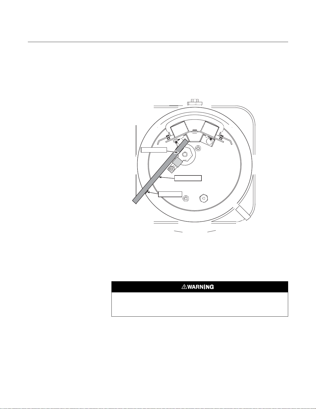
Instruction Manual
April 2017
OCX 8800
7-11
Eductor Flat
Straightedge
Matchmark
37390036
IM-106-880CIL, Rev 1.3
Figure 7-8. Eductor Alignment
Matchmarks
Remove Eductor
The O
cell and heater strut assembly (9, Figure 7-3) and the COe sensor
2
assembly (5, Figure 7-6) must be removed before you start this procedure.
1.
Use straightedge to matchmark alignment of eductor flat and elbow, as
shown in Figure 7-8.
2.
Unscrew terminal block mounting (13, Figure 7-6). Move terminal block
mounting away from eductor (6).
3.
Unscrew eductor holder (14) with eductor (6) and fittings (12 and 15)
from sensor housing (7).
4.
Clamp flats of eductor (6) in jaws of bench vise.
Use heat resistant gloves when removing mating parts from the eductor. The mating parts
are bonded with a thread sealing compound. The compound softens at 450°F (232°C). The
heated parts can cause severe burns.
5.
Use a propane torch to heat the eductor (6) to 450°F (232°C), minimum.
Apply the heat near the screw threads.
6.
While heating the eductor (6), use wrench to apply removal torque to
elbow (12), eductor holder (14), or tube fitting (15) until the thread
sealant softens. Remove mating parts (12, 14, and 15).
7.
Use MEK or methylene chloride solvent to clean thread sealant residue
from the pipe threads of the mating parts. Refer to applicable MSDS
sheet for solvent handling precautions.

Instruction Manual
880CIL, Rev 1.3
April 2017
OCX 8800
7-12
1 2 3
37390048
Figure 7-9. Removal of Sample
and Exhaust Tubes
1.
Sensor Housing
2.
Sample Tube
3.
Exhaust Tube
4.
In Situ Filter
4
IM-106-
Remove Sample and Exhaust Tubes
Use heat resistant gloves when removing the probe tube or exhaust tube. The tubes are
bonded with a thread sealing compound. The compound softens at 450°F (232°C). The
heated parts can cause severe burns.
1.
Secure the sensor housing (1, Figure 7-9) in soft (plastic, wood, or
brass) vice jaws.
2.
Use a propane torch to heat the sample tube (2) or exhaust tube (3) to
450°F (232°C), minimum. Appl y the h eat near t he thr e aded e nd of the
tube.
3.
While heating the t ube, use a pipe wrench to apply r emoval torque to
part being removed. Apply torque until the pipe thread sealant softens.
Remove and discard the used sample tube (2), exhaust tube (3), or
in-situ filter (4).
4.
Use MEK or methylene chloride solvent to clean thread sealant residue
from the internal pipe threads in the housing. Refer to applicable MSDS
sheet for solvent handling precautions.

Instruction Manual
April 2017
OCX 8800
7-13
37390032
IM-106-880CIL, Rev 1.3
Figure 7-10. O2 Cell, Heater,
and Thermocouple, Expl od ed
View
4
6
7
8
12
11
10
1. Screw
Cell
2. O
2
3. Heater Tube
4. Contact/
Thermocouple
Assembly
5. Gasket
6. Screw
7. Lockwasher
8. Return Wire
9. Heater Strut
Assembly
10. Spring Clip
11. Spring
12. Strut Bracket
3
5
Test Gas
Passage
Holes
2
1
Do not remove the O2 cell unless you are certain it needs to be replaced. Removal may
damage the cell and platinum pad. Remove the O
cell for cell replacement only.
2
Disassemble O2 Cell and Heater Strut Assembly
Do not attempt to replace the O2 cell until all other possibilities for poor
performance have been considered. If cell replacement is needed, order the
cell replacement kit (Refer to Section 9, Replacement Parts).
O
2
The O2 cell replacement kit contains an O2 cell and flange assembly, gaskets,
socket head cap screws, and anti-seize compound. The items are carefully
packaged to preserve precise surface finishes.
9
Do not remove items from the package until they are ready to be used.
1. Remove the four allen cap screws (1, Figure 7-10) from the O2 cell (2).
Remove the O2 cell. The cell flange has a notch that may be used to
gently pry the flange away from heater tube (3).
NOTE
The pad on the end of contact/thermocouple assembly (4) will sometimes
fuse to the O
cell (2).
2
2.
If the O2 cell is fused to t h e cont act pad, push the O2 cell back into the
heater tube (against spr ing pres s ure) and qu ickly twist the O
cell and contact pad should separate. If the contact pad stays fused to
the cell, a new contact/thermocouple assembly (4) must be installed.
3.
Remove and discard gasket (5). Clean the mating surface of heater
tube (3). Remove burrs and raised surfaces with a block of wood and
crocus cloth.
Use care when handling contact and thermocouple assembly. The ceramic rod in this
assembly is fragile.
4.
Remove screws (6), lockwashers (7), return wire (8), and heater strut
assembly (9).
5.
If replacing contact and thermocouple assembly (4), use a pencil to
mark location of spring clip (10) before removing. Squeeze tabs on
spring clip to remove. Retain spring clip and spring (11); replace if
damaged.
6.
While carefully handling new contact and thermocouple assembly (4)
lay old assembly next to new one. Transfer match marks to new
assembly.
7.
Carefully guide new contact and thermocouple assembly (4) through
strut bracket (12), spring (11), and spring clip (10) until spring clip
reaches pencil mark.
cell. The
2

Instruction Manual
880CIL, Rev 1.3
April 2017
OCX 8800
7-14
1
3 2
7 6 5 4
37390030
Figure 7-11. COe Sensor,
Exploded View
IM-106-
Disassemble COe Sensor Assembly
1.
Carefully remove screws (1, Figure 7-11), lockwashers (2), and COe
sensor (3) from sensor holder (4). Remove and discard gasket (5).
2.
If damaged, use the following procedure to remove thermocouple
adaptor (6) from sensor holder (4):
a.
Use a propane torch to heat the thermocouple adaptor to 450°F
(232°C), minimum.
b.
While heating, use a flat-head screwdriver to apply removal torque.
Apply torque until the pipe thread sealant softens. Remove and
discard the thermocouple adaptor.
c.
Use MEK or methylene chloride solvent to clean thread sealant
residue from the internal pipe threads in the sensor holder. Refer to
applicable MSDS sheet for solvent han dl ing precautions.
9
8
1.
Screw
2.
Lockwasher
3.
COe Sensor
4.
Sensor Holder
5.
Gasket
6.
Thermocouple Adapter
7.
Pre-Heater
8.
Plug
9.
Stainless Steel Balls

Instruction Manual
April 2017
OCX 8800
7-15
IM-106-880CIL, Rev 1.3
Sensor Housing Assembly
Always remove the stainless steel balls (approximately 200) from sensor holder before
removing or installing pre-heater. Turning pre-heater in t he sensor holder with the stainl ess
steel balls in place will cause permanent damage to the pre-heater.
3.
If pre-heater (7) is to be removed, clamp flats of sensor holder (4) in vise
jaws with plug (8) pointing up. Remove plug. Unclamp sensor holder
and pour stainless steel balls (9) into a container.
NOTE
Pre-heater should onl y be rem oved when pre-heater or sensor holder is
damaged. If rem oval is not requir e d, le ave the pr e-heater installed in the
sensor holder.
4.
Unthread and remove pre-heater (7).
5.
Use a cleaning solvent to thoroughly clean stainless steel balls (9) and
pre-heater chamber in sensor housing (4). Refer to applicable MSDS
sheet for solvent handling precautions.
Assemble COe Sensor Assembly
Always remove the stainless steel balls (approximately 200) from sensor holder before
removing or installing pre-heater. Turning pre-heater in the sensor holder with the stai nl ess
steel balls in place will cause permanent damage to the pre-heater.
1.
If pre-heater (7, Figure 7-11) was removed, apply pipe thread sealant
(Loctite #567) to the external pipe threads of pre-heater (7) and plug (8).
Do not apply sealant to the first turn of the pipe threads.
2.
Clamp flats of sensor holder (4) in vise jaws with pre-heater port
pointing up.
3.
Install and tighten pre-heater (7). Align pre-heater to flat of sensor
holder (4) as shown in Figure 7-12.
4.
Invert sensor holder (4, Figure 7-11) in vise and pour stainless steel
balls (9) into plug port. Press down on stainless steel balls and tap
sensor holder with plastic hammer to compact balls in pre-heater
chamber.
5.
Install and tighten plug (8).
Use care when installing the combustibles (COe) sensor. The RTD elements are fragile and
correct alignment in sensor holder is required for proper OCX operation.
6.
Lubricate and install COe sensor gasket (5). Apply anti-seize compound
to threads of screws (1).

Instruction Manual
880CIL, Rev 1.3
April 2017
OCX 8800
7-16
37390034
Figure 7-12. COe Sensor and
Pre-Heater Alignment
IM-106-
COe
SENSOR ASSEMBLY
THERMOCOUPLE
Sensor
Holder
Sensor
Holder
Flat
2 to 2-1/4 in.
(51 to 57 mm)
7.
Install COe sensor (3), lockwashers (2), and screws (1). Rotate flat of
TOP VIEW
COe Sensor
Flat
COe sensor (3) to center of sensor holder (4).
8.
Align COe sensor flat parallel to sensor holder flat, as shown in
Figure 7-12. Tighten screws (1, Figure 7-11).
9.
If replacing thermocouple adaptor (6), apply anti-seize to the pipe
threads. Install and tighten thermocouple adaptor.
Pre-Heater
Flat
Sensor
Holder
Flat
Assemble O
1.
See Figure 7-10. Assemble O2 cell (2), gasket (5), and heater tube (3).
Sensor and Heater Strut Assembly
2
Make sure the test gas passage holes line up with each other in all
components.
2.
Apply a small amount of anti-seize compound to the screw threads and
use screws (1) to secure assembly. Torque to 35 in-lbs (4 N·m).
3.
Carefully slide O2 heater strut assembly (9) into heater tube (3).
4.
Press down on the back plate of strut bracket (12) to ensure spring (11)
tension is present to hold contact pad against O
5.
Secure strut bracket (12) and return wire (8) with four screws (6) and
cell (2).
2
lockwashers (7). Make sure return wire (8) is tightly fastened. This is the
ground side connection for the O
cell.
2
Install Sample and Exhaust Tubes
1.
See Figure 7-9. Apply pipe thread sealant (Loctite #567) to the
replacement sample tube (2) or exhaust tube (3) pipe threads. Do not
apply sealant to the first turn of the pipe threads.
2.
Thread the sample tube (2) or exhaust tube (3) into the housing (1). Use
a pipe wrench to tighten the tube.
3.
If used, install and tighten in-situ filter (4).

Instruction Manual
April 2017
OCX 8800
7-17
37390047
IM-106-880CIL, Rev 1.3
Install Eductor
Figure 7-13. Installation of
Eductor and COe Sensor
8
10
12
14
7
11
If installed, the O
cell and heater strut assembly (9, Figure 7-3) must be
2
removed from sensor housing (8), before you install the eductor.
1.
Apply pipe thread sea lant ( Loctite #5 67) to the ex ternal pi pe thr eads of
eductor (6, Figure 7-13). Do not apply sealant to the first turn of the pipe
threads.
4
3
5
1
9
2
15
6
13
16
1. Insulator
2.
Dilution Air Tube
3.
COe Extractive Tube
4.
Eductor Air Tube
5.
COe Sensor Assembly
6.
Eductor
7.
Sensor Housing
8.
COe Thermocouple
9.
Heater Insulator
10.
COe Band Heater
11.
Sensor Holder
12.
Eductor Elbow
13.
Terminal Block Mounting
14.
Eductor Holder
15.
Tube Fitting
16.
CJC Sensor
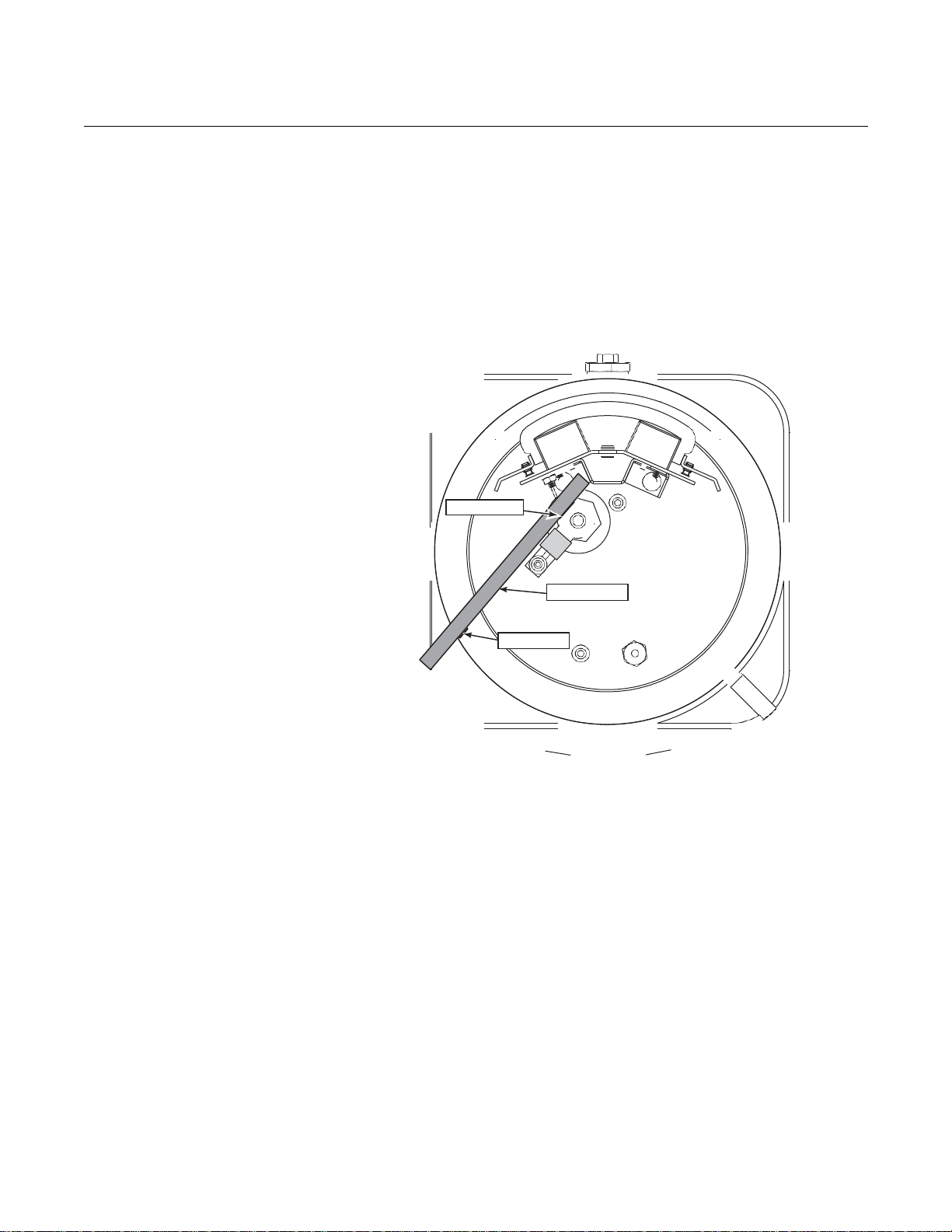
Instruction Manual
880CIL, Rev 1.3
April 2017
OCX 8800
7-18
Eductor Flat
Straightedge
Matchmark
37390036
Figure 7-14. COe Sensor
Parts Alignment
IM-106-
2.
Install and tighten eductor (6) in eductor holder (14).
3.
Install and tighten elbow (12) on eductor (6). Male port of elbow must
point up and be in line with long axis of eductor.
4.
Apply anti-seize compound to the external pipe threads of eductor
holder (14).
5.
Install and tighten eductor holder (14) in sensor housing (7). Align
eductor with matchmarks, as shown in Figure 7-14.
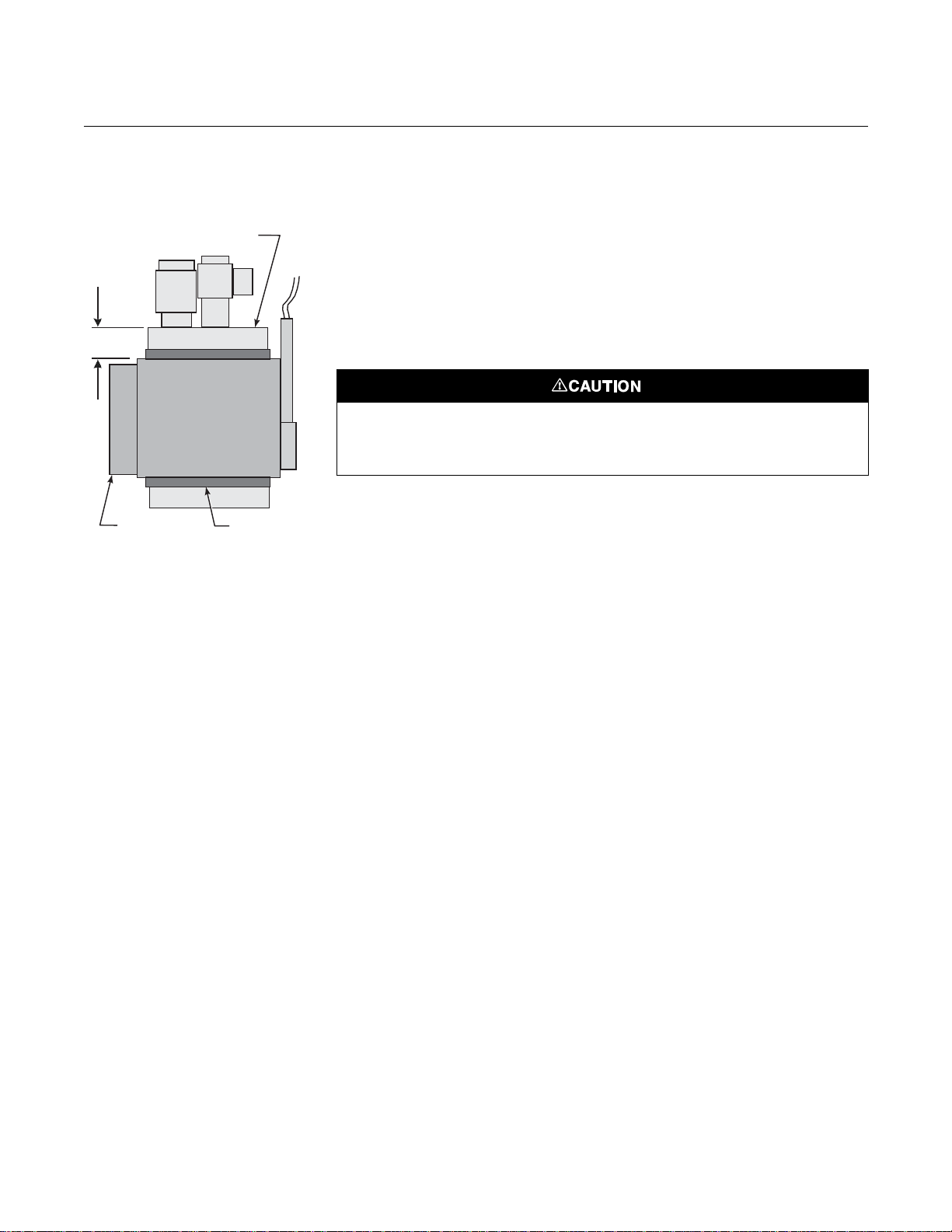
Instruction Manual
April 2017
OCX 8800
7-19
37390058
IM-106-880CIL, Rev 1.3
Install COe Sensor Assembly
Figure 7-15. Band Heater Height 1. Apply pipe thread sealant (Loctite #567) to the exposed pipe threads
of eductor elbow (12, Figure 7-13). Do not apply sealant to the first turn
0.37 in.
(9,4 mm)
COe Sensor
of the pipe threads.
2.
Screw sensor holder (11) onto eductor elbow (12).
3.
With wrenches on eductor elbow (12) and on flats of sensor holder (11),
tighten sensor holder. Do not allow eductor elbow to turn.
4.
Tighten sensor holder (11) to align outside flat with matchmark on
sensor housing flange, as shown in Figure 7-16.
The heater insulator prevents current leakage between the band heater and the sensor
holder. Failure to properly install the insulator may cause the device to trip a ground fault
interrupt circuit.
Band Heater
Insulator
5.
Wrap heater insulator (9) around sensor holder (11). Make sure the
insulator joint lines up with the band gap of the COe band heater (10).
6.
Slide COe band heater (10, Figure 7-13) up onto sensor holder (11). Do
not tighten the band heater at this time. Heater must rotate freely around
sensor holder.
7.
Check for proper height of COe heater thermocouple (Figure 7-12).
Thread bayonet connector up or down to adjust height.
8.
Install and fasten thermocouple (8, Figure 7-13).
9.
Position band heater as shown in Figure 7-15 and Figure 7-16 and
tighten band heater clamp screw. The heater insulator (9) end joint must
line up with the band gap of the COe band heater (10).

Instruction Manual
880CIL, Rev 1.3
April 2017
OCX 8800
7-20
Sensor
Holder
Flat
Matchmark
Straightedge
Matchmark
37390035
Figure 7-16. COe Sensor
Holder Alignment
IM-106-

Instruction Manual
April 2017
OCX 8800
7-21
HTR 02
- O2
T/C O2
+
RED
-
YEL
T/C CO
-
CJC Sensor
T/C SB
+
NOTE: All wires
at these terminals
are in the CJC
current loop.
-
EXC
Sensor
+
2
HTR 02
1
-
2
HTR CO
1
CO REF
+
-
HTR SB
1
CO ACT
+
+
EXC
COe Heater Wires
COe Thermocouple Wires
Sensor
Housing T
erminals
RED WHT
BLU RED BLU RED WHT
37390018
IM-106-880CIL, Rev 1.3
Figure 7-17. COe Sensor,
Thermocouple, and Heater
Connections
10.
Reconnect the COe sensor, thermocouple, and heater wires at the
sensor housing terminal blocks. Refer to Figure 7-17.
11.
Install and fasten the COe insulator (1, Figure 7-13) around COe sensor
assembly (5). All wiring must remain outside of the insulator.
12.
If terminal block mounting (13, Figure 7-13) was moved, reinstall with
two base mounting screws.
2
COe Sensor Wires
+
-
CJC
COe
Assembly
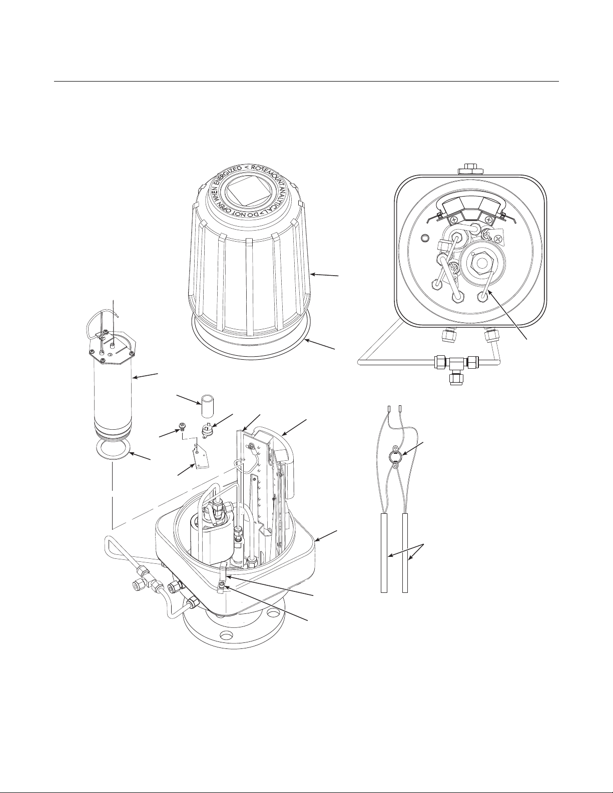
Instruction Manual
880CIL, Rev 1.3
April 2017
OCX 8800
7-22
Figure 7-18. Installation of O2 Cell
and Heater Strut Assembly
1. Screw
2. Locking Clip
3. Cover
4. O-ring
5. Marking Plate
6. Terminal Insulator
7. Reference Air Tube
8. Sensor Housing
9. Heater Strut Assembly
10. Gasket
11. Screw
12. Heater Clamp
13. Heater Rod
14. Insulator
15. Thermal Switch
IM-106-
3
11
10
4
9
14
5
15
12
6
15
8
13
2
1
7
37390066
Install Sample Block Heater Rods
1. Before installing sample block heater rods (13, Figure 7-18), evenly coat
the heater rods with Watlube heater release agent.

Instruction Manual
April 2017
OCX 8800
7-23
HTR 02
O
Heater Wires
Thermocouple Wires
+
+
+
- O2
ORG
RED
GRN
YEL
T/C O2
+
+ +
-
T/C CO
+
O2 Cell and Heater Strut
Assembly
-
+
-
EXC
-
Sample
Thermo-
couple
Sample Block
Heater Rods
CJC
+
2
HTR 02
1
-
2
HTR CO
1
CO REF
+
Thermal
Switch
-
2
HTR SB
1
CO ACT
+
+
EXC
Sensor
Housing T
erminals
Return Wire
37390069
IM-106-880CIL, Rev 1.3
Figure 7-19. O2 Cell,
Thermocouple, and
Heater Connections
O
2
2
Cell Wires
T/C SB
Block
2.
If thermal switch (15) was removed, install thermal switch on mating
heater clamp (12), connect wires of heater rods (13), and install
insulator (14).
3.
Install the heater rods (13), heater clamps (12), and screws (11).
4.
Reconnect the heater rod leads at the sensor housing terminal blocks,
(Figure 7-19).

Instruction Manual
880CIL, Rev 1.3
April 2017
OCX 8800
7-24
IM-106-
Install O2 Cell and Heater Strut Assembly
1.
Rub a small amount of anti-seize compound on both sides of new
gasket (10, Figure 7-18).
2.
Apply anti-seize compound to threads of O2 cell and heater strut
assembly (9) and sensor housing (8).
Stripped threads on the O2 cell and heater strut assembly can allow gas leakage. Gas
leakage can affect the O
and heater strut assembly.
measurements and calibration. Avoid over-tightening the O2 cell
2
3.
Install O2 cell and heater strut assembly (9) in sensor housing (8). Snug
up, but do not over-tighten the assembly.
4.
Reconnect the lead wires from O2 cell, heater, and thermocouple to the
sensor housing terminal blocks. Refer to Figure 7-19.
5.
Install reference air tube (7, Figure 7-18) in sensor housing (8). Make
sure that the open end of reference air tube extends into heater tube of
cell and heater strut assembly (9).
O
2
Install Terminals Insulator and Cover
1.
Install insulator (6, Figure 7-18) over uppermost terminal blocks.
Position one side of insulator against terminal blocks and snap terminal
marking plate (5) to mating stand-off.
2.
Position opposite side of insulator (6) and secure with relate d marking
plate (5).
3.
If removed, install cover gasket (4). Screw cover (3) onto sensor
housing (8). Tighten cover firmly.
4.
To comply with explosion-proof requirements, the cover gasket (4) must
be compressed. For hazardous area applications, verify that the cover
gasket is compressed.
5.
Align locking clip (2) with gap between cover ribs.
6.
Loosen screw (1) and slide locking clip (2) fully into gap between cover
ribs. Retighten screw (1).
Sensor Housing Leak Test
1.
Install 1/4 NPT cap on dilution air inlet fitting. Install a 1/4 NPT cap on
sample tube (2, Figure 7-9) or plug 1/4 NPT sample inlet port. Capped
or plugged ports must be air tight.
2.
If not in place, install exhaust tube (3, Figure 7-9) in exhaust port
according to the instructions provided.
3.
Connect a calibrated manometer to the CAL GAS inlet port.
4.
Connect and apply clean instrument air at 35 psig (241 kPa gage) to the
instrument air inlet fitting.
5.
Observe the manometer reading. The reading should be from 10 to 13
inches, Water Column. Locate and correct leaks if the reading is less
than 10 inches WC.

Instruction Manual
April 2017
OCX 8800
7-25
IM-106-880CIL, Rev 1.3
REPAIR ELECTRONICS HOUSING
Electronics Housing
Disassembly
Use the following procedures to remove damaged components from the OCX
8800 electronics housing and to install new replacement parts. Disassemble
the unit only as needed to replace damaged components. Use the assembly
procedures that apply to install replacement parts and reassemble the unit.
Remove Cover
1.
See Figure 7-20. Loosen screw (1) and slide locking clip (2) away from
cover (3). Retighten screw (1).
2.
With two hands or strap wrench, turn cover (3) counterclockwise to
loosen. Unthread and remove cover.
3.
Inspect cover gasket (4) for wear or damage. Replace cover gasket if
damaged.
Remove Flash PROM
Electrostatic discharge (ESD) protection is required to avoid damage to the electronic
circuits.
1.
Locate Flash PROM access port in electronics stack (5, Figure 7-20).
2.
Use suitable IC removal tool to remove Flash PROM (6).
Remove LOI Module and Board
1.
Remove three screws (7, Figure 7-20).
2.
Carefully lift LOI module (8) from LOI board (9). Note the location of LOI
connector (10).
3.
Remove two screws (11) and lockwashers (12). Remove LOI board (9).

Instruction Manual
880CIL, Rev 1.3
April 2017
OCX 8800
7-26
37390037
Figure 7-20. Removal/Installation of
Electronics Housing Components
1.
Screw
2.
Locking Clip
3.
Cover
O-ring
4.
5.
Electronics Stack
6.
Flash PROM
7.
Screw
8.
LOI Module
9.
LOI Board
10.
LOI Connector
11.
Screw
12.
Lockwasher
13.
Screw
14.
Lockwasher
15.
Solenoid Valve (3 way)
16.
Solenoid Valve
2
1
11
12
3
6
5
4
Remove Electronics Stack
10
IM-106-
8
7
9
13
14
15
16
1.
Unplug power cable, signal cable, and solenoid lead connectors from
terminals of electronics stack (5, Figure 7-20).
2.
Remove two screws (13) and lockwashers (14).
3.
Remove electronics stack (5).

Instruction Manual
April 2017
OCX 8800
7-27
37390081
IM-106-880CIL, Rev 1.3
Figure 7-21. Removal/
Installation of EMI Filter
Remove Solenoid Valves
1.
Disconnect solenoid leads from mating terminal connector.
2.
Remove top nut of solenoid valve (15 or 16, Figure 7-20).
3.
Remove the solenoid coil assembly and washer.
4.
Unthread and remove solenoid valve base.
Remove EMI Filter and Terminal Block
1.
Disconnect EMI filter wiring (Figur e 7-21) at terminal block (3).
2.
Disconnect EMI filter wiring at AC power input terminal block on
electronic stack.
3.
Unbolt and remove EMI filter (1) from electronic stack.
4.
Remove ground wire (2) from terminal block (3).
5.
Unbolt and remove terminal block (3) from electronic stack.
Brown
Blue
Green
Green
1
2
3
Blue
Brown
Green
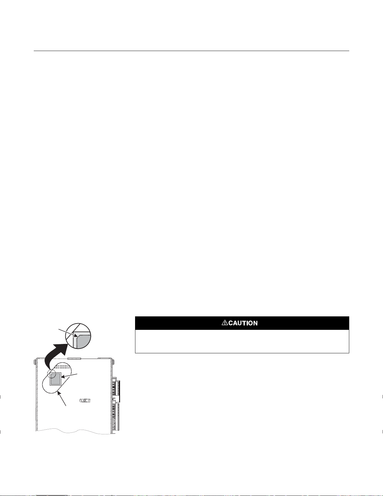
Instruction Manual
880CIL, Rev 1.3
April 2017
OCX 8800
7-28
37390060
IM-106-
Electronics Housing Assembly
Install EMI Filter and Terminal Block
1.
Install replacement EMI filter (1, Figure 7-21) and/or terminal block (3)
on electronic stack.
2.
Refer to wiring details in Figure 7-21. Connect EMI filter wiring and
ground wire (2) at terminal block (3).
3.
Connect EMI filter wiring at AC power input terminal block on electronic
stack.
Install Solenoid Valves
1.
Disassemble replacement solenoid valve (15 or 16, Figure 7-20).
2.
Install new solenoid valve base. Be careful not to overtighten.
3.
Install new washer and solenoid coil assembly and secure with nut.
4.
Connect the solenoid leads to the proper terminations on the solenoid
power terminal block (Figure 7-24).
Install Electronics Stack
1.
Install electronics stack (5, Figure 7-20) and secure with lockwashers
(14) and screws (13).
2.
See Figure 7-23 and Figure 7-24. Reconnect power cable, signal cable,
and solenoid lead connectors to electronics stack terminals.
Install LOI Module and Board
Figure 7-22. Flash PROM
Alignment
Corner
Bevel
Flash
PROM
Access
Port
1.
Install LOI board (9, Figure 7-20) and secure with two screws (11) and
lockwashers (12).
2.
Note the location of the LOI connector (10). Plug LOI module (8) and
connector into one of the four mating receptacles provided.
3.
Install three screws (7) to secure the LOI module.
Install Flash PROM
Electrostatic discharge (ESD) protection is required to avoid damage to the electronic
circuits.
1.
Locate Flash PROM access port in electronics stack (5, Figure 7-20).
2.
See Figure 7-22. Align Flash PROM (6, Figure 7-20) with mating
receptacle in access port of electronics stack as shown. Flash PROM
corner bevel must be in upper left corner of receptacle.
3.
Install Flash PROM (6).
Loading...