

Page 1

Instruction Manual
IM-106-880, Rev 2.1
April 2017
Rosemount
OCX 8800
Oxygen and Combustibles Transmitter
General Purpose Probe with Integral Electronics
TM
Page 2

Page 3

HIGHLIGHTS OF CHANGES
Page/Section Summary
Effective September 2009, Rev 2.0
Throughout IM Included coverage of all General Purpose OCX 8800 configurations/options into this single
Instruction Manual.
Added FOUNDATION Fieldbus communications option.
Added coverage of optional COe Purge/Zero function equipment illustrations with related
installation and operating procedures.
Added coverage of three optional in-situ filters.
Added coverage of optional wall-mount or rack-mount blowback panel.
Added coverage of PlantWeb Alert data for OCX 8800 units with FOUNDATION Fieldbus
communications.
Added Appendix B coverage of optional Moore Industries Site Pprogrammable Alarm for
OCX 8800 units with HART communications.
Effective April 2017, Rev 2.1
Page/Section Summary
Title page Removed Rosemount Analytical logo.
Updated Emerson logo.
Page 1-13 Updated Blowback Air specification.
Page 1-11 Updated specifications for Sensor Housings and Electronics Housings.
Page C-1 Updated Return of Materials information.
Back page Updated to include new addresses, social media information, and Rosemount and Emerson
logos.
Page 4

Page 5

Instruction Manual
IM-106-880, Rev 2.1
April 2017
OCX 8800
SECTION i
Introduction
SECTION 1
Description and
Specifications
SECTION 2
Installation
SECTION 3
Configuration and
Startup
Table of Contents
Essential Instructions ................................................................................ i
Preface .................................................................................................... iii
Definitions ............................................................................................... iii
Symbols .................................................................................................. iv
. . . . . . . . . . . . . . . . . . . . . . . . . . . . . . . . . . . . . . . . . . . . . . . . . . . . . . . . iv
Component Checklist ............................................................................ 1-1
System Overview .................................................................................. 1-3
Specifications ...................................................................................... 1-12
Mechanical Installation .......................................................................... 2-1
Electrical Installation ............................................................................. 2-8
Pneumatic Installation ......................................................................... 2-13
Initial Startup ....................................................................................... 2-24
Verify Installation ................................................................................... 3-1
Initial Power Up ..................................................................................... 3-5
Set Test Gas Values ............................................................................. 3-5
Calibration Solenoids ............................................................................ 3-6
Blowback Feature ................................................................................. 3-7
Calibration Verify Feature ..................................................................... 3-9
Calibration Tolerance Feature ............................................................ 3-11
COe Purge / Zero Feature .................................................................. 3-12
OCX 8800 Reset Procedure ............................................................... 3-14
SECTION 4
Using the LOI
SECTION 5
Calibration
Overview ............................................................................................... 4-1
Display Orientation ................................................................................ 4-1
LOI Controls .......................................................................................... 4-2
Overview .......................................................................................... 4-2
LOI Key Functions ........................................................................... 4-2
LOI Status Codes ............................................................................ 4-3
LOI Menu Tree ...................................................................................... 4-4
Overview ............................................................................................... 5-1
Fully Automatic Calibration ................................................................... 5-1
Operator - Initiated Autocalibration ....................................................... 5-3
Manual Calibration ................................................................................ 5-4
D/A Trim Procedures - LOI ................................................................. 5-12
D/A Trim Procedures - HART ............................................................. 5-14
Page 6

Instruction Manual
IM-106-880, Rev 2.1
April 2017
OCX 8800
TOC-2
SECTION 6
Field Communicator
SECTION 7
Foundation Fieldbus
Overview ............................................................................................... 6-1
Field Communicator Connections ......................................................... 6-1
Off-Line and On-Line Operations .......................................................... 6-4
Hart Menu Tree ..................................................................................... 6-5
Fieldbus Menu Tree .............................................................................. 6-9
Foundation Fieldbus Technology .......................................................... 7-1
Overview .......................................................................................... 7-1
Introduction ...................................................................................... 7-2
Instrument-Specific Function Blocks................................................ 7-4
Network Communication .................................................................. 7-4
OCX Function Blocks ............................................................................ 7-6
Resource Block ..................................................................................... 7-6
PlantWeb Alerts ............................................................................... 7-6
Mapping of PWA .............................................................................. 7-7
PWA Simulate ................................................................................ 7-10
Fieldbus/PWA Simulate ................................................................. 7-10
Configure Simulation with the Model 375 Field Communicator . . 7-11
Support Resource Block Errors ..................................................... 7-13
Transducer Block ................................................................................ 7-13
Transducer Block Parameters ....................................................... 7-13
Transducer Block Enumerations.................................................... 7-17
Transducer Block Channel Assignments for AI Blocks ................. 7-22
Transducer Block Channel Status ................................................. 7-22
Transducer Block Simulate ............................................................ 7-23
Support Transducer Block Errors .................................................. 7-23
Analog Input (AI) Function Block ........................................................ 7-23
Introduction .................................................................................... 7-23
Simulation ...................................................................................... 7-26
Filtering .......................................................................................... 7-27
Signal Conversion .......................................................................... 7-27
Block Errors ................................................................................... 7-28
Modes ............................................................................................ 7-29
Alarm Detection ............................................................................. 7-29
Status Handling ............................................................................. 7-29
Advanced Features ........................................................................ 7-30
Application Information .................................................................. 7-30
Application Examples .................................................................... 7-31
Troubleshooting ............................................................................. 7-35
Proportional/Integral/Derivative (PID) Function Block ........................ 7-36
Setpoint Selection and Limiting ..................................................... 7-40
Filtering .......................................................................................... 7-41
Feedforward Calculation ................................................................ 7-41
Tracking ......................................................................................... 7-41
Output Selection and Limiting ........................................................7-41
Bumpless Transfer and Setpoint Tracking .................................... 7-41
PID Equation Structures ................................................................ 7-42
Reverse and Direct Action ............................................................. 7-42
Reset Limiting ................................................................................ 7-42
Block Errors ................................................................................... 7-42
Modes ............................................................................................ 7-43
Alarm Detection ............................................................................. 7-44
Page 7

Instruction Manual
IM-106-880, Rev 2.1
April 2017
OCX 8800
Status Handling ............................................................................. 7-44
Application Information .................................................................. 7-45
Application Examples .................................................................... 7-46
Troubleshooting ............................................................................. 7-51
Arithmetic (ARTHM) Function Block ................................................... 7-52
Block Errors ................................................................................... 7-54
Modes ............................................................................................ 7-55
Alarm Detection ............................................................................. 7-55
Block Execution ............................................................................. 7-55
Status Handling ............................................................................. 7-56
Application Information .................................................................. 7-56
Advanced Topics ........................................................................... 7-57
Troubleshooting ............................................................................. 7-59
Input Selector (ISEL) Function Block .................................................. 7-59
Block Errors ................................................................................... 7-61
Modes ............................................................................................ 7-61
Alarm Detection ............................................................................. 7-62
Block Execution ............................................................................. 7-62
Status Handling ............................................................................. 7-62
Application Information .................................................................. 7-63
Troubleshooting ............................................................................. 7-64
Operation with Emerson DeltaV.......................................................... 7-65
About AMS and DeltaV Software ................................................... 7-65
SECTION 8
Troubleshooting
SECTION 9
Maintenance and Service
SECTION 10
Replacement Parts
Overview ............................................................................................... 8-1
Grounding ........................................................................................ 8-1
Electrical Noise ................................................................................ 8-1
Electrostatic Discharge .................................................................... 8-1
Total Power Loss ............................................................................. 8-2
Diagnostic Alarms ................................................................................. 8-2
Fault Isolation ........................................................................................ 8-3
Alarm Relay Events............................................................................. 8-11
Overview ............................................................................................... 9-1
OCX 8800 Removal and Installation ..................................................... 9-1
OCX with Integral Electronics .......................................................... 9-2
OCX with Remote Electronics ......................................................... 9-5
Repair Sensor Housing ....................................................................... 9-10
Sensor Housing Disassembly ........................................................ 9-10
Sensor Housing Assembly ............................................................. 9-20
Repair Electronics Housing ................................................................. 9-29
Electronics Housing Disassembly .................................................. 9-29
Electronics Housing Assembly ...................................................... 9-31
Replace Tube Fittings ......................................................................... 9-35
Remove Tube Fittings .................................................................... 9-35
Install Tube Fittings ........................................................................ 9-36
Sensor Housing................................................................................... 10-2
Electronics Housing ............................................................................ 10-6
O2 Cell and Heater Strut Assembly ....................................................10-9
TOC-3
Page 8

Instruction Manual
IM-106-880, Rev 2.1
April 2017
OCX 8800
TOC-4
APPENDIX A
Safety Data
APPENDIX B
SPA with HART Alarm
APPENDIX C
Return of Materials
Safety Instructions . . . . . . . . . . . . . . . . . . . . . . . . . . . . . . . . . . . . . . . . A-2
Safety Data Sheet for Ceramic Fiber Products . . . . . . . . . . . . . . . . . A-24
High Pressure Gas Cylinders . . . . . . . . . . . . . . . . . . . . . . . . . . . . . . A-30
Overview . . . . . . . . . . . . . . . . . . . . . . . . . . . . . . . . . . . . . . . . . . . . . . . B-1
Description. . . . . . . . . . . . . . . . . . . . . . . . . . . . . . . . . . . . . . . . . . . . . . B-1
Installation . . . . . . . . . . . . . . . . . . . . . . . . . . . . . . . . . . . . . . . . . . . . . . B-2
Setup . . . . . . . . . . . . . . . . . . . . . . . . . . . . . . . . . . . . . . . . . . . . . . . . . . B-2
Returning Material . . . . . . . . . . . . . . . . . . . . . . . . . . . . . . . . . . . . . . . .C-1
Page 9

Instruction Manual
IM-106-880, Rev 2.1
April 2017
OCX 8800
If a Model 375 Field Communicator is used with this unit, the software within the Model 375
may require modification. If a software modification is required, please contact your local
Emerson Service Group or National Response Center at
1-800-654-7768.
ESSENTIAL
INSTRUCTIONS
Oxygen/Combustibles Transmitter
READ THIS PAGE BEFORE PROCEEDING!
Emerson designs, manufactures and tests its products to meet many national
and international standards. Because these instruments are sophisticated
technical products, you MUST properly install, use, and maintain them to
ensure they continue to operate within their normal specifications. The
following instructions MUST be adhered to and integrated into your safety
program when installing, using, and maintaining Emerson’s Rosemount
products. Failure to follow the proper instructions may cause any one of the
following situations to occur: Loss of life; personal injury; property damage;
damage to this instrument; and warranty invalidation.
•
Read all instructions prior to installing, operating, and servicing the
product.
•
If you do not understand any of the instructions, contact your
Emerson representative for clarification.
•
Follow all warnings, cautions, and instructions marked on and
supplied with the product.
•
Inform and educate your personnel in the proper installation,
operation, and maintenance of the product.
•
Install your equipment as specified in the Installation Instructions
of the appropriate Instruction Manual and per applicable local and
national codes. Connect all products to the proper electrical and
pressure sources.
•
To ensure proper performance, use qualified personnel to install,
operate, update, program, and maintain the product.
•
When replacement parts are required, ensure that qualified people use
replacement parts specified by Emerson. Unauthorized parts and
procedures can affect the product's performance, place the safe
operation of your process at risk, and VOID YOUR WARRANTY.
Look-alike substitutions may result in fire, electrical hazards, or
improper operation.
•
Ensure that all equipment doors are closed and protective covers
are in place, except when maintenance is being performed by
qualified persons, to prevent electrical shock and personal injury.
The information contained in this document is subject to change without
notice.
Page 10

Instruction Manual
IM-106-880, Rev 2.1
April 2017
OCX 8800
ii
Page 11
Instruction Manual
IM-106-880, Rev 2.1
April 2017
OCX 8800
Highlights an operation or maintenance procedure, practice, condition, statement, etc. If not
strictly observed, could result in injury, death, or long-term health hazards of personnel.
Highlights an operation or maintenance procedure, practice, condition, statement, etc. If not
strictly observed, could result in damage to or destruction of equipment, or loss of
effectiveness.
Section i Introduction
Preface . . . . . . . . . . . . . . . . . . . . . . . . . . . . . . . . . . . . . . . . . page iii
Definitions . . . . . . . . . . . . . . . . . . . . . . . . . . . . . . . . . . . . . . page iii
Symbols . . . . . . . . . . . . . . . . . . . . . . . . . . . . . . . . . . . . . . . . page iv
PREFACE The purpose of this manual is to provide a comprehensive understanding of
the OCX 8800 components, functions, installation, and maintenance.
We recommend that you thoroughly familiarize yourself with the Introduction
and Installation sections before installing your transmitter.
The introduction presents the basic principles of the transmitter along with its
performance characteristics and components. The remaining sections contain
detailed procedures and information necessary to install and service the
transmitter.
Before contacting Emerson concerning any questions, first consult this
manual. It describes most situations encountered in your equipment's
operation and details necessary action.
DEFINITIONS The following definitions apply to WARNINGS, CAUTIONS, and NOTES
found throughout this publication.
NOTE
Highlights an essential operating procedure, condition, or statement.
Page 12

Instruction Manual
IM-106-880, Rev 2.1
April 2017
OCX 8800
iv
SYMBOLS
NOTE TO USERS
The number in the lower right corner of each illustration in this publication is a
manual illustration number. It is not a part number, and is not related to the
illustration in any technical manner.
NOTE
Read this manual before working with the product. For personal and system
safety, and for optimum product performance, make sure you thoroughly
understand the contents before installing, using, or maintaining this product.
Page 13

Instruction Manual
IM-106-880, Rev 2.1
April 2017
OCX 8800
Section 1 Description and Specifications
Component Checklist . . . . . . . . . . . . . . . . . . . . . . . . . . . . . page 1-1
System Overview . . . . . . . . . . . . . . . . . . . . . . . . . . . . . . . . page 1-3
Specifications . . . . . . . . . . . . . . . . . . . . . . . . . . . . . . . . . . . page 1-12
Product Matrix - OCX 8800 . . . . . . . . . . . . . . . . . . . . . . . . . page 1-14
COMPONENT
CHECKLIST
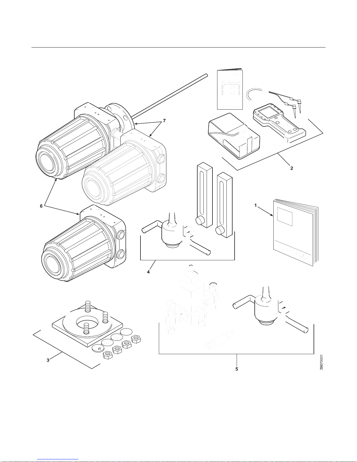
A typical OCX 8800 Oxygen/Combustibles Transmitter package should
contain the items shown in Figure 1-1.
Use the product matrix in Table 1-1 at the end of this section to verify your
order number. The first part of the matrix defines the model. The last part
defines the various options and features of the OCX 8800. Check the model
number against the transmitter features and options, making sure options
specified by this number are on or included with the unit. Use this complete
model number for any correspondence with Emerson. A list of accessories for
use with the OCX 8800 is provided in Table 1-2.
Page 14
Instruction Manual
IM-106-880, Rev 2.1
April 2017
OCX 8800
1-2
Figure 1-1. Typical System Package
1.
Instruction Manual
2.
Field Communicator Package (optional)
3.
Adapter Plate with Mounting Hardware and Gasket
4.
Reference Air and Calibration Set (optional)
5.
Blowback Hardware (optional)
6.
OCX 8800 with Remote Electronics
7.
OCX 8800 with Integral Electronics
Page 15

1-3
Instruction Manual
IM-106-880, Rev 2.1
April 2017
OCX 8800
SYSTEM OVERVIEW Scope
This Instruction Manual supplies details needed to install, startup, operate,
and maintain the OCX 8800. Signal conditioning electronics outputs a digital
signal representing oxygen (O2) and combustibles (COe) values. This
information, plus additional details, can be accessed with the 375 Field
communicator or Emerson AMS software. The optional
local operator interface (LOI) also provides a communications interface with
the electronics.
System Description
The OCX 8800 is designed to measure oxygen and combustible
concentrations in flue gas temperatures up to 2600°F (1427°C). Electrical
connections, power and communications are made through two 3/4 NPT ports
in the flameproof electronics enclosure using fittings and cables provided by
the customer. Cable installation must meet NEC, IEC and/or other applicable
national or local codes for Class I, Zone 1, Group IIB +H2 T3/T6 permanently
mounted equipment. The transmitter is close coupled to the process and
requires minimal sample conditioning requirements.
The equipment measures oxygen percentage by reading the voltage
developed across a heated electrochemical cell, which consists of a small
yttria-stabilized, zirconia disc. Both sides of the disc are coated with porous
metal electrodes. When operated at the proper temperature, the millivolt
output of the cell is given by the following Nernst equation:
EMF = KT log10 (P1/P2) + C
Where:
1.
P2 is the partial pressure of the oxygen in the measured gas on one side
of the cell.
2.
P1 is the partial pressure of the oxygen in the reference air on the
opposite side of the cell.
3.
T is the absolute temperature.
4.
C is the cell constant.
5.
K is an arithmetic constant.
NOTE
For best results, use clean, dry instrument air (20.95% oxygen) as the
reference air.
When the cell is at operating temperature and there are unequal oxygen
concentrations across the cell, oxygen ions will travel from the high oxygen
partial pressure side to the low oxygen partial pressure side of the cell. The
resulting logarithmic output voltage is approximately 50 mV per decade. The
output is proportional to the inverse logarithm of the oxygen concentration.
Therefore, the output signal increases as the oxygen concentration of the
sample gas decreases. This characteristic enables the OCX 8800 to provide
exceptional sensitivity at low oxygen concentrations.
Page 16

1-4
Instruction Manual
IM-106-880, Rev 2.1
April 2017
OCX 8800
The OCX 8800 measures net oxygen concentration in the presence of all the
products of combustion, including water vapor. Therefore, it may be
considered an analysis on a "wet" basis. In comparison with older methods,
such as the portable apparatus, which provides an analysis on a "dry" gas
basis, the "wet" analysis will, in general, indicate a lower percentage of
oxygen. The difference will be proportional to the water content of the
sampled gas stream.
The OCX 8800 combustibles sensor is a catalytic sensor consisting of two
Resistance Devices (RTD). One RTD is the reference element covered with
an inert coating. The other RTD element is active, coated with a catalyst. As
the sample gases flow by the sensor, the combustible gases oxidize on the
surface of the active element. The oxidation that occurs produces heat and a
temperature rise in the active element. The temperature difference produces
a resistance relationship between the two elements that is directly
proportional to the concentration of combustibles in the sample gases.
The catalyst is specifically designed to detect carbon monoxide (CO), but the
sensor responds to other combustible gases. The sensor is calibrated using
CO, thus the output should be expressed in terms of CO. However, since the
sensor detects other combustible gases, the output cannot just be labeled
CO. The response of the sensor to other combustible gases gives an output
that is equivalent to the sensor detecting CO.
The term COe is used in this manual to describe the sensor output. This term
indicates that the sensor is calibrated in terms of CO, and that the sensor
output is equivalent to CO but not specific to CO.
Dilution air is provided to the COe sensor to ensure there is adequate oxygen
to fully oxidize any combustible gases regardless of the concentration of
oxygen in the process.
System Configuration
Transmitters are available in four lengths, giving the user the flexibility to use
a penetration appropriate to the size of the stack or duct. The length options
are 18 in. (457 mm), 3 ft (0.91 m), 6 ft (1.83 m), or 9 ft (2.7 m). Probes are
available in three material options, 316L stainless steel, Inconel 600, and
ceramic to accommodate higher temperatures.
The electronics are contained in a separate housing from the sensors. When
the transmitter is configured with the integral electronics option the electronics
and sensor housings are mounted as a unit at the stack mounting flange.
When the transmitter is configured with the remote electronics option the
electronics are contained in a separate housing from the sensors. The
electronics housing may be mounted up to 150 feet from the sensor housing.
The electronics control both sensor temperatures and provide output signals
in one of two ways:
1.
Individual 4-20 ma isolated outputs that are proportional to the
measured oxygen and combustibles concentrations. The oxygen output
also contains HART communication.
2.
Single FOUNDATION fieldbus output.
Page 17

1-5
Instruction Manual
IM-106-880, Rev 2.1
April 2017
OCX 8800
The power supply can accept voltages of 100 to 240 VAC and 50 to 60 Hz.
The electronics accepts millivolt signals generated by the sensors and
produces the outputs to be used by remotely connected devices. Refer to
Section 3, Configuration and Startup for specific instructions upon initial
power up.
System Features
1.
The O2 cell output voltage and sensitivity increase as the oxygen
concentration decreases.
2.
HART or FOUNDATION fieldbus communication is standard. To use this
capability, you must have either:
a.
Model 375 Field Communicator.
b.
AMS software for the PC.
3.
Oxygen cell and heater/thermocouple assembly are field replaceable.
4.
Electronics are automatically configured for line voltages from 100 to
240 VAC.
5.
An operator can calibrate and diagnostically troubleshoot the OCX 8800
in one of two ways:
a.
LOI. The LOI is mounted to the end of the electronics module and
allows local communications with the electronics. Refer to Section 4,
Using the LOI, for more information.
b.
HART or FOUNDATION fieldbus interface. The OCX 8800's output
line transmits a digital signal with the detected oxygen or
combustible levels encoded in a digital format. This information can
be accessed through the following:
•
Model 375 Field Communicator - The handheld field
communicator requires Device Description (DD) software specific
to the OCX 8800. The DD software will be supplied with many
Model 375 units, but can also be programmed into existing units
at most Emerson service offices. Refer to Section 6, Field
Communicator, for additional information.
•
Personal Computer (PC) - The use of a personal computer
requires AMS software available from Emerson.
•
Selected Distributed Control Systems - The use of distributed
control systems requires input/output (I/O) hardware and AMS
software which permit HART or FOUNDATION fieldbus
communications.
6.
When the transmitter is configured without the LOI an operator must
calibrate and diagnostically troubleshoot the OCX 8800 using the HART
or FOUNDATION fieldbus Interface.
7.
Optional Blowback System. The blowback system periodically blows
instrument air back through the sample line filter and out the sample
tube. This clears out particulate and keeps the sample line filter from
clogging.
Page 18
1-6
Instruction Manual
IM-106-880, Rev 2.1
April 2017
OCX 8800
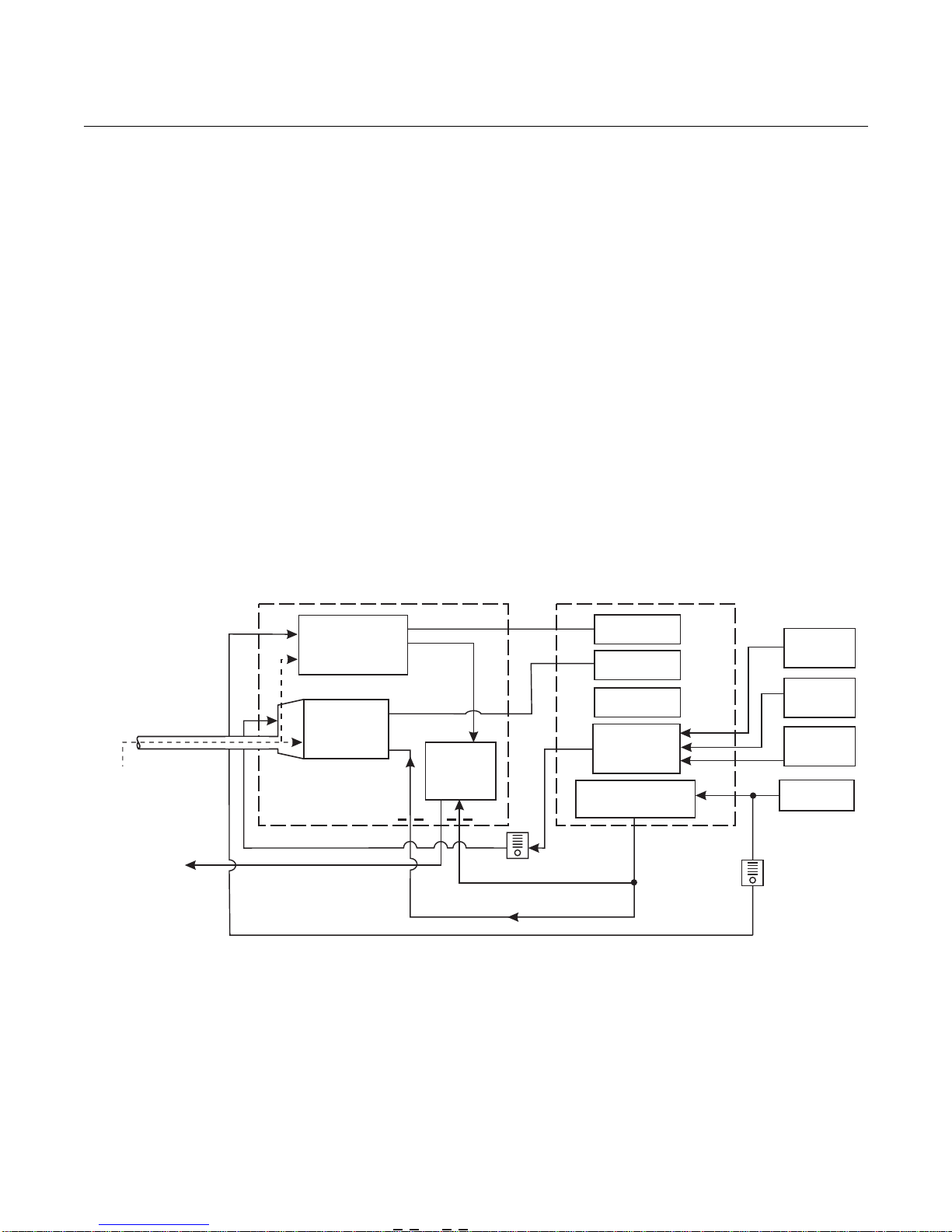
System Operation
Figure 1-2 shows the relationship between the components of the OCX 8800.
The sensors and the electronics are contained in separate housings. The
sensor housing and probe mounts to a duct or process wall so that the probe
protrudes into the flue gas stream. An air powered eductor continuously pulls
samples of the process flue gas through the probe to a chamber in front of the
sensor housing where the sample passes the O2 sensor and continues on to
the COe sensor. Dilution air is provided to the COe sensor and reference air
to the O2 sensor. After the gas sample flows past the O2 sensor and through
the COe sensor, it is drawn through the eductor where it mixes with the
eductor air and exits through exhaust back into the system. The electronics
housing contains the CPU and communication boards which convert the
sensor inputs into digital output signals. The CPU can also initiate and
perform calibrations. Three test gasses and instrument air can be turned on
and off by solenoids. Test gas flow to the sensors is regulated by a flow meter
between the electronics and sensor housings. Instrument air is separated into
eductor air, reference air, and dilution air. The instrument air solenoid does not
allow air flow until the heaters are up to temperature. This minimizes the
amount of sampled process flue gas being pulled into cold sensors causing
condensation.
Figure 1-2. System Operation Diagram
SENSOR
HOUSING
ELECTRONICS
HOUSING
Sample
Gas
Exhaust
Probe
COe
Combustibles
Sensor
O
2
Sensor
Eductor
Eductor Air
Solenoids
Instrument Air
Flow Meter
7 scfh
Reference Air
CPU
COMM
Board
Power
Supply
Optional
Test Gas
Solenoid
Dilution Air
Low O
Test Gas
High O
Test Gas
CO
Test Gas
Instrument
Air
Flow Meter
50 cc/min.
(0.1 scfh)
2
2
39690001
Page 19

1-7
Instruction Manual
IM-106-880, Rev 2.1
April 2017
OCX 8800
It is important that printed circuit boards and integrated circuits are handled only when
adequate antistatic precautions have been taken to prevent possible equipment damage.
The OCX 8800 is designed for industrial application. Treat each component of the system
with care to avoid physical damage. The probe may contain components made from
ceramics, which are susceptible to shock when mishandled.
Handling the OCX 8800
System Considerations
Prior to installing your OCX 8800, make sure you have all the components
necessary to make the system installation. Ensure all the components are
properly integrated to make the system functional.
After verifying that you have all the components, select mounting locations
and determine how each component will be placed in terms of available line
voltage, ambient temperatures, environmental considerations, convenience,
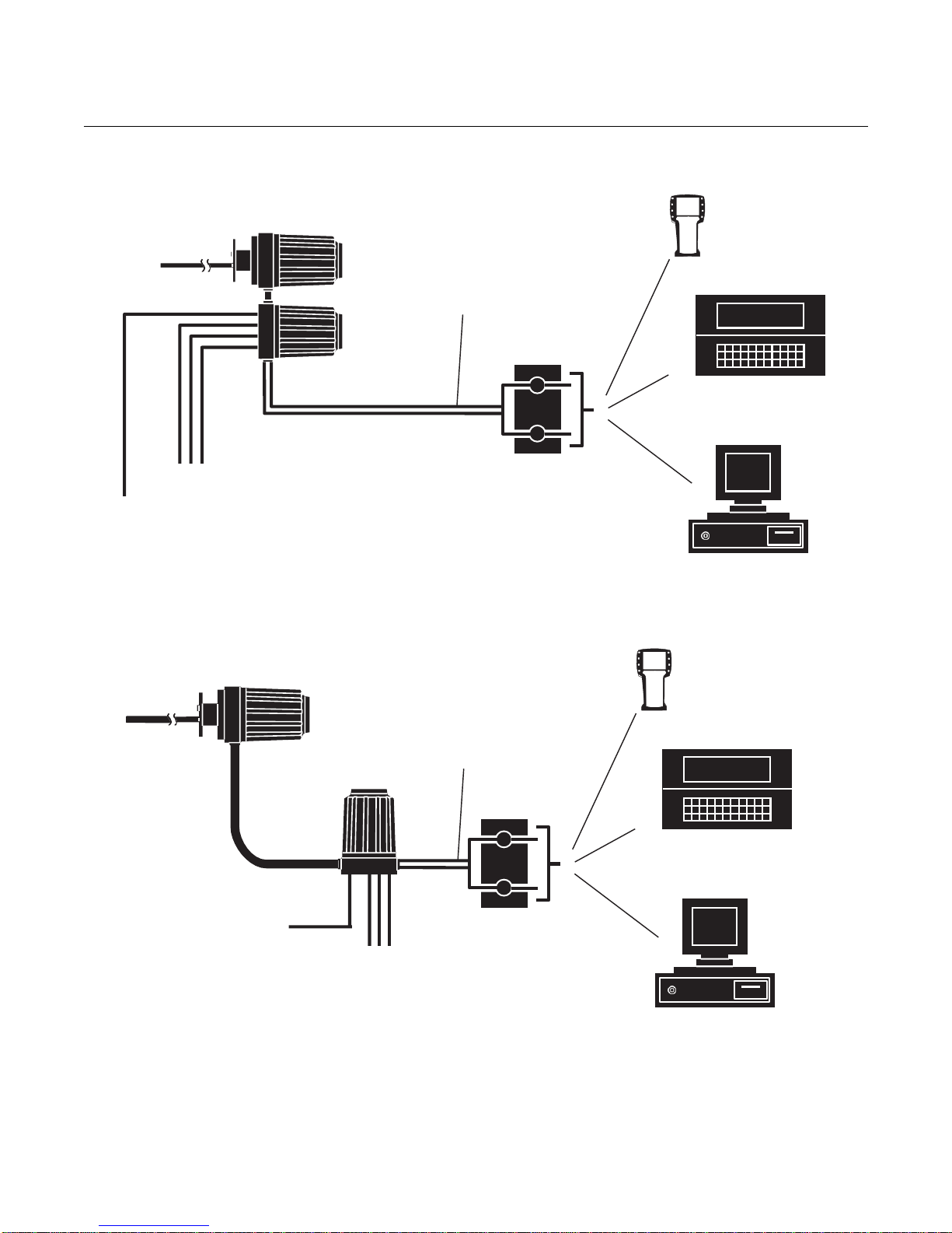
and serviceability. Figure 1-3 shows a typical system wiring for a system with
integral electronics. Figure 1-4 shows a typical system wiring for a system
with remote electronics. Simplified installations for the OCX 8800 are shown
in Figure 1-5 and Figure 1-6. Figure 1-7 shows the dimensions for the
optional sample tube support. Figure 1-8 shows the dimensions for the
optional in-situ filters. Figure 1-9 shows the optional panel mounted blowback.
A source of instrument air is required at the OCX 8800 for reference air,
dilution air, and eductor air. Since the OCX 8800 is equipped with an in-place
calibration feature, provision should be made for connecting test gas tanks to
the OCX 8800 when it is to be calibrated.
NOTE
The electronics module is designed to meet Type 4X and IP66 (when
reference air vents are routed to a dry area) and the electronic components
are rated to temperatures up to 185°F (85°C).
Retain packaging in which the unit arrived from the factory in case any
components are to be shipped to another site. This packaging has been
designed to protect the product.
Page 20
1-8
Instruction Manual
IM-106-880, Rev 2.1
April 2017
OCX 8800
Figure 1-3. Communication Connections and AMS Application - OCX 8800 with Integral Electronics
38850004
38850003
Model 375
Field
Communicator
Customer’s
Laptop with AMS
AMS
Instrument
Air
OCX 8800 with
Integral Electronics
3 calibration
gas lines by
customer
[300 ft (91 m) max.)
Signal Output
(Twisted Pairs)
Termination in
Control Room
Figure 1-4. Communication Connections and AMS Application - OCX 8800 with Remote Electronics
OCX 8800
Sensor Housing
Instrument
Air
OCX 8800
Electronics Housing
3 calibration
gas lines by
customer
[300 ft (91 m) max.)
(Twisted Pairs)
Signal Output
Termination in
Control Room
Model 375
Communicator
Customer’s
Laptop with AMS
AMS
Field
Page 21
1-9
Instruction Manual
IM-106-880, Rev 2.1
April 2017
OCX 8800
Figure 1-5. Typical System Installation - Integral Electronics
Gases
Stack
Test Gas
Flow Meter
Dilution
Air
Flow
Meter
Adapter
Plate
Duct
Figure 1-6. Ty pical System Installation - Remote Electronics
Gases
OCX 8800 with
ELECTRONICS
Pressure
Regulator
High O Test Gas
2
Low O Test Gas
2
CO Test Gas
Duct
INTEGRAL
Signal Outputs
(Twisted Pairs)
Line Voltage
Instrument Air
Supply
(Reference Gas)
37390063
OCX 8800 with
REMOTE
ELECTRONICS
Heater
Power Cable
[up to 150 ft (46 m)]
Signal Cable
[up to 150 ft (46 m)]
Stack
Dilution
Air
Flow
Meter
Test Gas
Flow Meter
Pressure
Regulator
High O Test Gas
Low O Test Gas
CO Test Gas
Signal Outputs
(Twisted Pairs)
Line Voltage
Instrument Air
Supply
(Reference Gas)
2
2
37390064
Page 22

1-10
Instruction Manual
IM-106-880, Rev 2.1
April 2017
OCX 8800
Figure 1-7. Optional Sample Tube Support
Page 23
Instruction Manual
IM-106-880, Rev 2.1
April 2017
OCX 8800
1-11
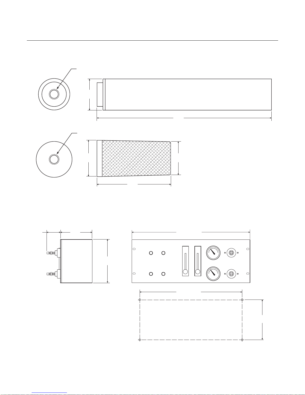
Figure 1-8. Optional InSitu Filters
1/4-18 NPT
1.3
(33)
1/4-18 NPT
7.3
(186)
InSitu Stainless Steel or Hastolloy Filter
2.0
(50)
4.0
(102)
1.8
(46)
InSitu High Surface Area Stainless Steel Filter
Figure 1-9. Optional Panel Mounted Blowback and Calibration/Reference Air Set (19” Rack or Wall Mount)
2.2
(55.9)
5.00
(127)
6.97
(177)
CALIBRATION/BLOWBACK
PANEL
OCX 8800
PROCESS ANALYTICAL DIVISION
1-440-914-1261
www.raihome.com
19.00 (482.6)
DILUTION GAS CAL GAS
16.5 (419.1)
Wall Mount
SET TO 55 PSIG BLOWBACK AIR
OCX88A: 35 PSIG
OCX88C: 45 PSIG
PRESSURE
REFERENCE AIR
PRESSURE
39930006
Wall Mount Hole Pattern
6.0 (152.4)
Wall Mount
39930007
Page 24

Instruction Manual
IM-106-880, Rev 2.1
April 2017
OCX 8800
1-12
SPECIFICATIONS
Specifications
Net O2 Range 0-1% to 0-40% O2, fully field selectable
Combustibles 0-1000 ppm to 0-5%, fully field selectable
Accuracy
Oxygen ± 0.75% of reading or 0.05% O2 (whichever is greater)
Combustibles ± 2% range
System Response to
Test Gas
Oxygen 10 sec T90
Combustibles 25 sec T90
Temperature Limits
Process 32° to 2600°F (0° to 1427°C)
Sensors Housing -40° to 212°F (-40° to 100°C), ambient
Electronics Housing -40° to 149°F (-40° to 65°C), ambient
-40° to 185°F (-40° to 85°C), internal - operating temperature of
electronics inside instrument housing, as read by HART or
FOUNDATION fieldbus
Local Operator
Interface
Nominal and Approximate
Shipping Weights
18 in. (457 mm)
probe package
3 ft (0.91 m) probe
package
6 ft (1.83 m) probe
package
9 ft (2.74 m) probe
package
Housings Mounting Integral Electronics
Mounting and Mounting
Positions - Remote
Electronics
Sensors Housing Flange
Electronics Housing Wall/Pipe
Materials
Probes 316L stainless steel - 1300°F (704°C)
Enclosures Low-copper aluminum
Calibration Semi-automatic or automatic
Calibration Gas Mixtures
Recommended
(Ref. test gas bottles
kit #1A99119G04)
Calibration Gas Flow 7 scfh (3.3 l/m), regulated to 20 to 30 psi (138 to 207 kPa)
Reference Air 2 scfh (1 l/m), clean, dry instrument-quality air (20.95% O2),
Eductor Air 5 scfh (2.5 l/m), clean, dry, instrument-quality air 20.95% O2),
Dilution Air 0.1 scfh (0.05 l/m), clean, dry, instrument-quality air (20.95% O2)
Table continued on next page
-40° to 158°F (-40° to 70°C), ambient
[At temperatures above 158°F (70°C) inside instrument housing,
the infrared keypad will cease to function, but the OCX 8800 will
continue to operate properly.]
54 lbs (20 kg)
55 lbs (20.5 kg)
57 lbs (21 kg)
59 lbs (22 kg)
Flange
Inconel 600 - 1832°F (1000°C)
Ceramic - 2600°F (1427°C)
0.4
8% O2, Balance N2
1000 ppm CO, Balance Air
regulated to 35 psi (241 kPa)
regulated to 35 psi (241 kPa)
regulated to 35 psi (241 kPa)
% O2, Balance N
2
Page 25
Instruction Manual
IM-106-880, Rev 2.1
April 2017
OCX 8800
1-13
Blowback Air (optional) Clean, dry, instrument-quality air (20.95% O2), regulated to ≥ 60 psi
(413 kPa) or greater and ambient temperature of ≥ 0 °F (-18 °C)
Specifications
Sensors Housing Type 4X, IP66 with fitting and pipe on reference exhaust port to
clean, dry atmosphere, two 3/4-14 NPT conduit ports (when
reference air vents are routed to a dry area).
Electronics Housing Type 4X, IP66 with fitting and pipe on reference exhaust port to
clean, dry atmosphere, two 3/4-14 NPT conduit ports (when
Certifications
Electrical Noise EN 61326-1, Class A
Line Voltage Universal 100 to 240 VAC ±10%, 50 to 60 Hz, no switches or
Pollution Degree 2
Over Voltage Category II
Relative Humidity 5 to 95% (non-condensing)
Isolated Output
Oxygen 4-20 mAdc, 950 ohm maximum, with HART or FOUNDATION
Combustibles 4-20 mAdc, 950 ohm maximum (Not present with FOUNDATION
Alarm Alarm output relay - dry contact, form C, 30mA, 30VDC capacity
Power Consumption 750 W maximum
NOTE
All static performance characteristics are with operating variables constant. Specifications subject to change
without notice.
reference air vents are routed to a dry area).
jumpers required, 3/4-14 NPT conduit port
fieldbus capability only
fieldbus)
Page 26
Instruction Manual
IM-106-880, Rev 2.1
April 2017
OCX 8800
1-14
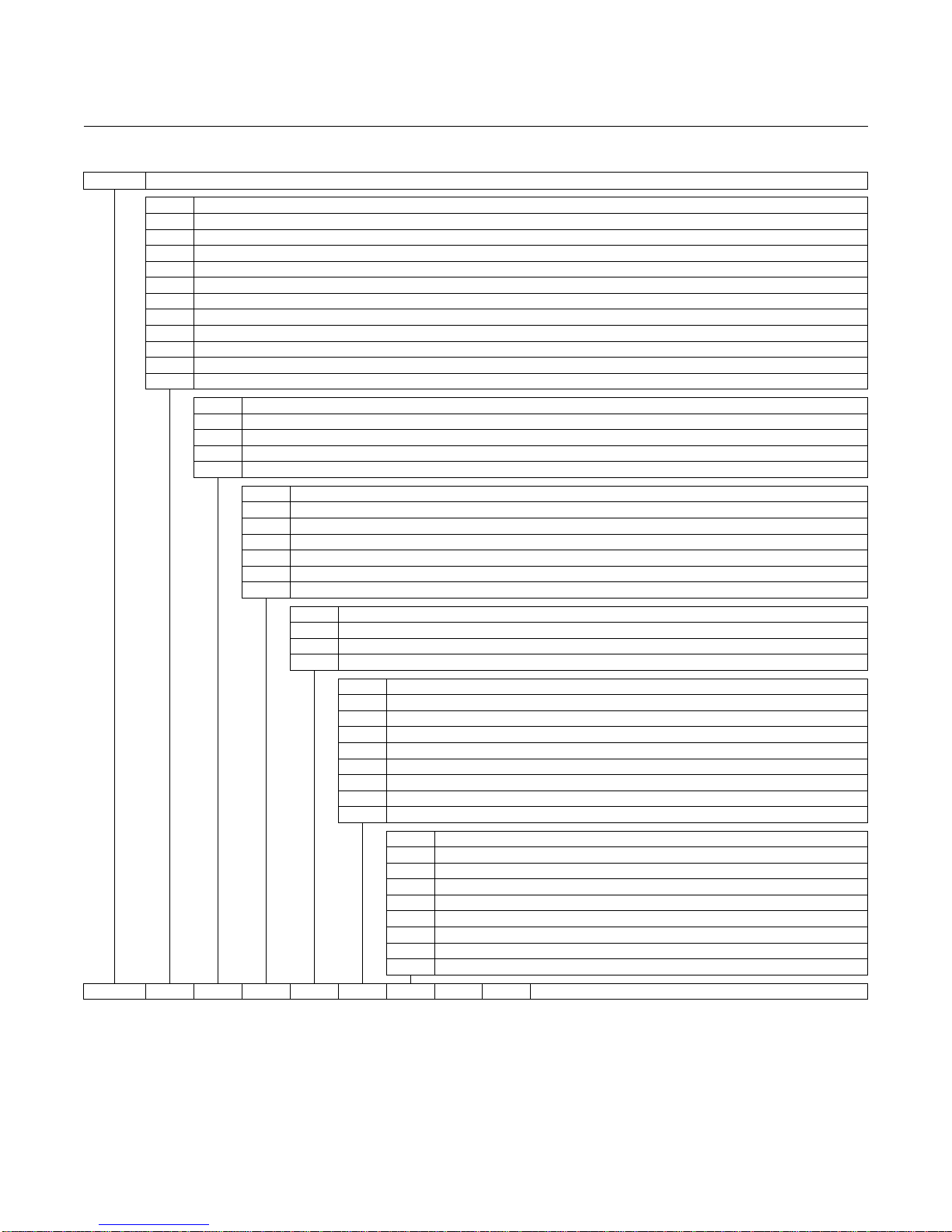
OCX88A
O2/Combustibles Transmitter
Code
Probe Length and Material
00
No Probe or Exhaust Tube
11
18 in. (457 mm) 316 SST
up to 1300°F (704°C)
12
3 ft (0.91 m) 316 SST
up to 1300°F (704°C)
13
6 ft (1.83 m) 316 SST
up to 1300°F (704°C)
14
9 ft (2.7 m) 316 SST
up to 1300°F (704°C)
21
18 in. (457 mm) Inconel 600
up to 1832°F (1000°C)
22
3 ft (0.91 m) Inconel 600
up to 1832°F (1000°C)
23
6 ft (1.83 m) Inconel 600
up to 1832°F (1000°C)
24
9 ft (2.7 m) Inconel 600
up to 1832°F (1000°C)
31
18 in. (457 mm) Ceramic
up to 2600°F (1427°C)
32
3 ft (0.91 m) Ceramic
up to 2600°F (1427°C)
Code
Probe Mounting Assembly
10
(ANSI 2 in. 150 lb) 6" dia. flange, 4.75" BC with 4 x 0.75" dia. holes - Standard O2 Cell
11
(ANSI 2 in. 150 lb) 6" dia. flange, 4.75" BC with 4 x 0.75" dia. holes - High Sulfur O2 Cell
20
(DIN) 185 mm dia. flange, 145 mm BC with 4 x 18 mm dia. holes - Standard O2 Cell
21
(DIN) 185 mm dia. flange, 145 mm BC with 4 x 18 mm dia. holes - High Sulfur O2 Cell
Code
Mounting Hardware - Stack Side
0 No Adapter Plate (“0” must be chosen under “Mounting Adapter - Probe Side” below)
1 New Installation - Square weld plate with studs
2 Model 218/240 Mounting Plate (with Model 218/240 Shield Removed)
3 Existing Model 218/240 Support Shield
4 Competitor’s Mount
(1)
5 Model 132 Adapter Plate
Code
Mounting Hardware - Probe Side
0 No Adapter Plate
1 Probe Only (ANSI)
4 Probe Only (DIN)
Code
Electronics Housing - NEMA 4X, IP66 HART Communications
H1
HART Communications - Basic Unit
H2
HART Communications - Local Operator Interface
H3
HART Communications - Calibration Solenoids
H4
HART Communications - Local Operator Interface and Calibration Solenoids
F1
Fieldbus Communications - Basic Unit
F2
Fieldbus Communications - Local Operator Interface
F3
Fieldbus Communications - Calibration Solenoids
F4
Fieldbus Communications - Local Operator Interface and Calibration Solenoids
Code
Electronics Mounting
01
Integral to Sensor Housing Electronics
02
Split Architecture with no cable
03
Split Architecture with 6M (20 Ft.) cable
04
Split Architecture with 12M (40 Ft.) cable
05
Split Architecture with 18M (60 Ft.) cable
06
Split Architecture with 24M (80 Ft.) cable
07
Split Architecture with 30M (100 Ft.) cable
08
Split Architecture with 45M (150 Ft.) cable
OCX88A
11
10 1 1
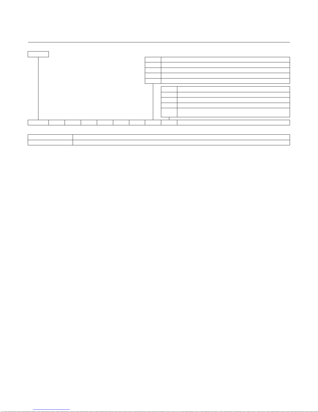
H3
06
Example
Table 1-1. Product Matrix - OCX 8800
Page 27
Instruction Manual
IM-106-880, Rev 2.1
April 2017
OCX 8800
1-15
Cont’d
.
Code
In-Situ Filter
0 None 1
Stainless Steel
2 High Surface Area Stainless Steel
3 Hastelloy
Code
Accessories
0 None 2
Cal. Gas/Flow Rotometers & Ref. Gas Set
3 Cal. Gas/Flow Rotometers & Ref. Gas Set w/ Blowback
4
Cal. Gas/Flow Rotometers & Ref. Gas Set w/ Blowback - Panel
Mounted
OCX88A
11
10 1 1
H3
06 0 0
Example
Plate with studs
Bolt circle diameter, number, and arrangement of studs, stud thread, stud height above mounting plate.
Plate without studs
Bolt circle diameter, number, and arrangement of holes, thread, depth of stud mounting plate with accessories.
NOTES:
(1)
Provide details of the existing mounting plate as follows:
Page 28

Instruction Manual
IM-106-880, Rev 2.1
April 2017
OCX 8800
1-16
PART NUMBER DESCRIPTION
Table 1-2. Accessories
1A99119H01 Oxygen test gas bottle; 0.4% O2, balance N
1A99119H02 Oxygen test gas bottle; 8.0% O2, balance N
1A 99119H07 CO test gas bottle; 1000 ppm CO, balance air
1A99120H02 Regulator for Oxygen (may need 2)
1A99120H03 Regulator for CO test gas
1A99119G06 Wall mount bracket for test gas bottles
1A99119G05 Test gas regulators kit
1A99119G04 Test gas bottles kit
1A99292H01
4851B40G02 Wall or Pipe Mounting Kit
1A99784H02
6A00171G01 Power line filter kit
6A00288G01 Sample Tube Support, 18 in. (457 mm)
6A00288G02 Sample Tube Support, 3 Ft. (0.91 m)
6A00288G02 Sample Tube Support, 6 Ft. (1.83 m)
6A00288G04 Sample Tube Support, 9 Ft. (2.7 m)
6P00162H01 Flange Insulator
Moore Industries SPA for Low O2 Alarm, High COe Alarm,
Calibration Status, and Unit Fail
375 Field Communicator with 12 Megabyte buffer,
model no. 375HR1EKLU
2
2
Page 29
Instruction Manual
IM-106-880, Rev 2.1
April 2017
OCX 8800
Before installing this equipment, read the "Safety instructions for the wiring and installation
of this apparatus" in Appendix A: Safety Data. Failure to follow the safety instructions could
result in serious injury or death.
The OCX88A can be installed in general purpose areas only. Do not install the OCX88A in
hazardous areas.
Section 2 Installation
Mechanical Installation . . . . . . . . . . . . . . . . . . . . . . . . . . . page 2-1
Electrical Installation . . . . . . . . . . . . . . . . . . . . . . . . . . . . . page 2-8
Pneumatic Installation . . . . . . . . . . . . . . . . . . . . . . . . . . . . page 2-13
Initial Startup . . . . . . . . . . . . . . . . . . . . . . . . . . . . . . . . . . . . page 2-24
MECHANICAL
INSTALLATION
Selecting Location
1.
The location of the OCX 8800 in the stack or flue is most important for
maximum accuracy in the oxygen analyzing process. The probe must
be positioned so the gas it measures is representative of the process.
Best results are normally obtained if the transmitter is positioned near
the center of the duct (40-60% insertion). Longer ducts may require
several transmitters since the oxygen and combustibles can vary due to
stratification. A point too near the wall of the duct or the inside radius of
a bend, may not provide a representative sample because of the very
low flow conditions. The sensing point should be selected so the
process gas temperature falls within the range of probe material used.
Figure 2-1 through Figure 2-5 provide mechanical installation
references. The ambient temperature inside the electronics housing
must not exceed 185°F (85°C).
2.
Check the flue or stack for holes and air leakage. The presence of this
condition will substantially affect the accuracy of the oxygen and
combustibles readings. Therefore, either make the necessary repairs or
install the transmitter up stream of any leakage.
3.
Ensure the area is clear of internal and external obstructions that will
interfere with installation and maintenance access to the unit. Allow
adequate clearance for the removal of the OCX 8800.
Page 30
Instruction Manual
IM-106-880, Rev 2.1
April 2017
OCX 8800
2-2
Do not allow the temperature of the electronics housing to exceed 185°F (85°C) or damage
to the electronics may result.
Whenever a positive stack pressure exists at the installation site, be sure to connect all
pneumatic lines prior to installing the OCX 8800 in the stack or ductwork. Failure to connect
the pneumatic lines can allow the flow of contaminants into the OCX 8800 ports.
Uninsulated stacks or ducts may cause ambient temperatures in the electronics housing to
exceed 185°F (85°C) and damage the electronics.
Installation
1.
Ensure all components are available to install the OCX 8800.
2.
The OCX 8800 may be installed intact as it is received.
3.
Weld or bolt adapter plate (Figure 2-3) onto the duct.
4.
Use the pipe or wall mounting hardware as shown in Figure 2-4 to
mount a remote electronics housing. Choose a location not to exceed
the length of the electronics cable ordered.
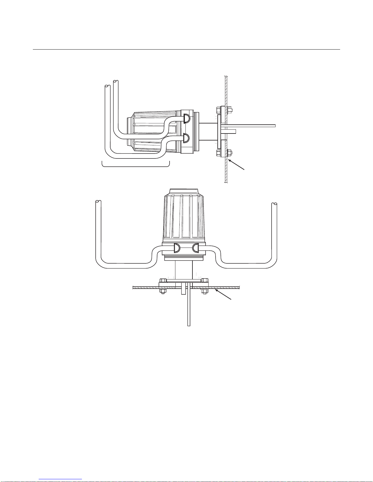
5.
Ensure the conduits drop vertically from the OCX 8800 and the conduit
is routed below the level of the conduit ports on the housing to form a
drip loop. Drip loops minimize the possibility that moisture will damage
the electronics (Figure 2-5).
6.
Where a positive stack pressure exists at the installation site, connect all
pneumatic lines prior to installing the OCX 8800 in the stack or
ductwork.
NOTE
If process temperatures will exceed 392°F (200°C), use anti-seize compound
on stud threads to ease future removal of the OCX 8800.
7.
Insert sample and exhaust tubes through the opening in the mounting
flange and bolt the unit to the flange.
8.
If insulation is removed to access the duct for OCX 8800 mounting,
make sure to replace insulation afterward.
Page 31

Instruction Manual
IM-106-880, Rev 2.1
April 2017
OCX 8800
2-3
Enclosures
The OCX 8800 enclosures are designed to meet ingress conditions of Type
4X and IP66 (when reference air vents are routed to a dry area). Each
enclosure cover is threaded to its base and sealed with an o-ring that isolates
the threads from external contaminants.
Each cover is secured by a clip attached to the base that engages the cover
between the ribs of the cover sidewall. The clip is held in place by an Allen
head cap screw and lockwasher mounted in a recess. Cover removal and
installation requires an Allen wrench to loosen and tighten the screw.
Figure 2-1. Installation, OCX 8800 with Integral Electronics
NOTE
All dimensions are in inches with millimeters in parentheses.
Insulate if exposed to adverse weather or extreme temperature changes,
install a protective housing and/or insulation around the unit.
0.06 In. Thick Gasket
ANSI
DIN
3535B18H02
3535B45H01
Flange Dia.
B.C. Dia.
Hole Dia.
Table 1. Mounting Flange
ANSI
Flange
Dia.
Hole
Dia.
(4) Holes
equally
spaced on
B.C. dia
6.00
(152)
0.75
(19)
4.75
(121)
DIN
7.28
(185)
0.71
(18)
5.71
(145)
Allow 9 in.
(229 mm) for
Cover Removal
Dim “B”
Removal Envelope
BOTTOM VIEW
Dim “A”
Insertion Depth
Table 2. Installation/Removal
Probe Dim “A” Dim “B”
18 in.
3ft
6ft
9ft
18
(457)
36
(914)
72
(1829)
108
(2743)
Optional
In Situ Filter
*
*4.0 (101.6) with high surface
*7.3 (186.4) with Stainless Steel
Stainless Steel Filter
or Hastelloy Filter
34
(864)
52
(1321)
88
(2235)
124
(3150)
37390008
Page 32

Instruction Manual
IM-106-880, Rev 2.1
April 2017
OCX 8800
4-2
Figure 2-2. Installation, OCX 8800 with Remote Electronics
Page 33

Instruction Manual
IM-106-880, Rev 2.1
April 2017
OCX 8800
2-5
Figure 2-3. Adapter Plate Installation
Page 34

Instruction Manual
IM-106-880, Rev 2.1
April 2017
OCX 8800
6-2
Figure 2-4. Wall or Pipe Mounting of Electronics Housing
Page 35
Instruction Manual
IM-106-880, Rev 2.1
April 2017
OCX 8800
2-7
Conduit Drip Loops
Duct Wall
Conduit Drip Loop
Conduit Drip Loop
Duct Wall
37020004
Figure 2-5. Installation with Drip Loops
Page 36

Instruction Manual
IM-106-880, Rev 2.1
April 2017
OCX 8800
8-2
Disconnect and lock out power before connecting the unit to the power supply. Failure to
lock out power could result in serious injury or death.
Install all protective equipment covers and safety ground leads after installation. Failure to
install covers and ground leads could result in serious injury or death.
To meet the Safety Requirements of IEC 1010 (EC requirement), and ensure safe operation
of this equipment, connection to the main electrical power supply must be made through a
circuit breaker (min 10 A) in close proximity and marked for this equipment which will
disconnect all current-carrying conductors during a fault situation. This circuit breaker
should also include a mechanically operated isolating switch. If not, then another external
means of disconnecting the supply from the equipment should be located close by. Circuit
breakers or switches must comply with a recognized standard such as IEC 947.
The OCX88A can be installed in general purpose areas only. Do not install the OCX88A in
hazardous areas.
ELECTRICAL
INSTALLATION
All wiring must conform to local and national codes. For reference, factory
wired solenoid power connections are shown in Figure 2-6.
NOTE
To maintain proper earth grounding, ensure a positive connection exists
between the sensor housing, the electronics housing, and earth. The
connecting ground wire must be 14 AWG minimum. Refer to Figure 2-6.
NOTE
Line voltage, signal, and relay wiring must be rated for at least 105ºC (221ºF).
Electrical Connections
Electrical connections, power and communications are made to the electronic
enclosure. The connections are made through two 3/4 NPT ports in the
enclosure using fittings and cables provided by the customer. Cable
installation must meet NEC, IEC and/or other applicable national or local
codes for Class I, Zone 1, IIB +H2 T3/T6 permanently mounted equipment.
Page 37

Instruction Manual
IM-106-880, Rev 2.1
April 2017
OCX 8800
2-9
Connect Line Voltage
The OCX 8800 operates on 100 to 240 VAC line voltage at 50 to 60 Hz. The
power supply requires no setup. Connect the line (L wire) to the L terminal,
and the neutral (N wire) to the N terminal on the AC power input terminal
block in the electronics housing. Connect the ground (G wire) to the ground
stud in the electronics housing as shown in Figure 2-6.
Connect Output Signals
The OCX 8800 may be provided with either two 4-20 mA signals with HART
on the O2 signal or a single FOUNDATION fieldbus signal. Connect the
output terminals in the electronics housing as shown in Figure 2-6. Use
individual shielded twisted wire pairs. Terminate the shield at the electronics
housing.
O2 4-20 mA Signal
One 4-20 mA signal represents the O2 value. Superimposed on the O
signal is the HART information accessible through a Model 375 Handheld
Communicator or AMS software. The O2 signal is at the AOUT 1 terminals.
COe 4-20 mA Signal
Another 4-20 mA signal at the AOUT 2 terminals represents the COe
value.
FOUNDATION fieldbus Signal
The FOUNDATION fieldbus signal provides all output information and is
accessible through a Model 375 handheld communicator.
2
Alarm Output Relay
Connect any customer-supplied relay input to the alarm output relay terminal.
Use shielded wire and terminate the shield at the electronics housing. The
alarm output relay terminal is a set of dry, no. 2, form C, contacts with 30 mA,
30 VDC capacity.
Remote Electronics Connections to Sensor Housing
Make the following connections between the remote electronics and sensor
housings with the electronics cable ordered with the package (Figure 2-7).
Braided cable is available in lengths up to 150 ft. (46 m).
NOTE
Interconnect wiring shown is for Rosemount supplied cables. For customer
furnished interconnect wiring or cables, refer to Figure 2-8.
Signal Connections
Connect the electronics housing terminals to the corresponding terminals
in the sensor housing. The twisted wire pairs are numbered on the inner
plastic wrapper. Keep twisted pairs together and match the numbers and
wire colors shown in Figure 2-7.
Heater Power Connections
Use the blue, white, orange black, red, and yellow stranded wires in the
heater power cable to connect power to the three heaters in the sensor
housing. Match the wire colors to the corresponding heater power terminal
blocks in the sensor and electronics housings as shown in Figure 2-7.
Page 38

Instruction Manual
IM-106-880, Rev 2.1
April 2017
OCX 8800
Figure 2-6. Line Voltage, Earth, and 4-20 mA Connections
#1
NC
COM
NO
Alarm Output Relay
Terminal Block
F
Not used
F
OUNDATION
Fieldbus
OUNDATION
Fieldbus
-
{
+
-
{
+
OR
COe Signal
O Signal/
2
HART
HART
AOUT2+
{
AOUT2 -
AOUT1 -
{
AOUT1+
Signal Output
Terminal Block
TOP VIEW
(1/2 SIZE)
Ground Stud
Typical for Electronics and
Sensor Housing
2-10
Earth Ground
EMI Filter
Customer
#1
Wiring
Signal Port
3/4 NPT
Terminal
G
L1
N
Block
G
Ground
Stud
Power Port
3/4 NPT
G
External Tooth
Lockwasher
37390013
Page 39

Instruction Manual
IM-106-880, Rev 2.1
April 2017
OCX 8800
2-11
Figure 2-7. Electrical Connections Between Remote Electronics and Sensor Housing
YEL
RED
BLK
ORG
WHT
BLU
Heater Power
Connector (J3)
RED
BLK
WHT
BLK
GRN
BLK
BLU
BLK
Heater Power Cable
#1
O Sensor and
2
Thermocouple
Connector (J5)
T/C CO+
T/C CO-
T/C SB+
T/C SBT/C O2+
T/C O2-
O2 CELL+
O2 CELL-
SHLD
#1
2HTR CO
1HTR CO
2HTR O
1HTR O
2HTR SB
1HTR SB
To ground
2
2
screw
#1
#1 #1
YEL
BRN
BLK
RED
WHT
ORG
BLK
BLK
#1
EXC+
CO ACT+
CO ACT-
CO REF+
CO REFCJC+
CJCEXC-
GRN
SHIELD
To
ground
screw
COe Sensor
and
Cold Junction
Connector (J4)
ELECTRONICS HOUSING
BLK
GRN
Signal Cable
-
+
BLU
+
T/C O2
O2
-
BLK
BLK
-
RED
+
T/C CO
BLK
-
WHT
+
T/C SB
BLK
EXC-
BLK
-
ORG
CJC
SENSOR HOUSING
CO
BRN
+
ACT
2
WHT
HTR
YEL
+
EXC
SB
1
BLU
To ground screw
GRN
37390014
WHT
RED
BLK
+
REF
2
YEL
HTR
-
CO
1
RED
2
BLK
HTR
-
CO
O2
1
ORG
+
Page 40
Instruction Manual
IM-106-880, Rev 2.1
April 2017
OCX 8800
2-12
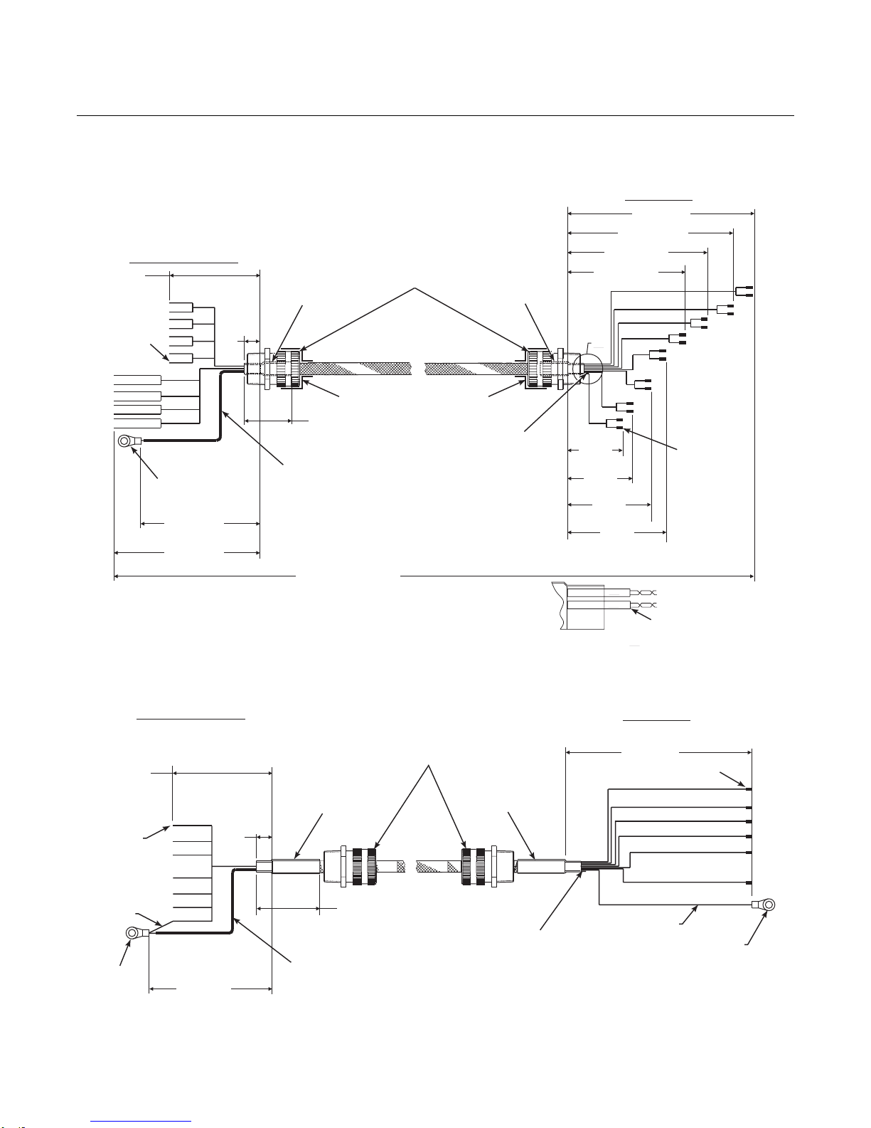
Figure 2-8. Customer-Furnished Interconnect Wiring or Cables
SIGNALWIRING OR CABLE
NOTE: For RFI/CE compliance, the connector
must provide 360 degrees of electrical
contact to the cable shield.
ELECTRONICS END
7.25
±0.10
Strip Wire
Ends 3/16”
Typical
Stud Size
#10
7.25 ±0.10
9.25 ±0.10
0.5
Typ.
Heat Shrink
Tubing
2” Long
1/2” Size
2.0 ±0.25
Typical
7.0” Long Teflon Tubing,
0.042” ID (Cut off drain
wire at probe end of
shield).
Overall Cable Length
By Customer
150’Maximum
3/4 NPT Hub Size,
Liquid-tight
Strain Relief
Connector
See Note
Heat Shrink
Tubing
2” Long
1/2” Size
See Note
8 twisted pairs 24 AWG,
stranded, insulated,
tinned copper
conductors, 200 C, 300
volts, with overall braid
of 34 AWG tinned
copper, 90% coverage
and 24 AWG tinned
copper, uninsulated
drain wire.
o
(typical on both ends of wiring)
8.625 ±0.10
6.875 ±0.10
A
3.875
±0.10
4.625
±0.10
5.375
±0.10
6.125
±0.10
#1
#2
DETAIL
PROBE END
12.5 ±0.10
10.375 ±0.10
Heat Shrink Tubing
1” Long, 3/16” Size
A
Ferrule,
Uninsulated
ELECTRONICS END
4.0 ±0.10
Heat Shrink Tubing
Strip Wire
Ends 3/16”
Typical
Green,
16 AWG
Stud Size
#10
4.5 ±0.10
0.5
Typ.
HEATERWIRING OR CABLE
3/4 NPT Hub Size,
Liquid-tight
Strain Relief
Connectors
2” Long, 1/2” Size
2.0 ±0.25 Typical
4.25” Long Teflon Tubing,
0.042” ID.(Cut off drain wire
at probe end of shield).
PROBE END
5.5 ±0.10
Ferrule, Uninsulated
Heat Shrink Tubing
2” Long, 1/2” Size
Green, 16 AWG
8 Conductors, 16 AWG, Stranded,
O
200 C, 600 volts.
Braided shield - tinned copper, 90%
coverage with 18 AWG 24 tinned copper,
uninsulated, drain wire.
Stud Size #6
37390061
Page 41

Instruction Manual
IM-106-880, Rev 2.1
April 2017
OCX 8800
2-13
PNEUMATIC
Do not use 100% nitrogen as an O2 low gas. It is suggested that O2 low gas be between
0.4% and 2.0% O2. Do not use gases with hydrocarbon concentrations of more than 40
parts per million. Failure to use proper gases will result in erroneous readings.
INSTALLATION
Pneumatic system connections depend on whether reference air set,
calibration solenoids, and/or blowback equipment options are equipped on
your transmitter. Refer to the following paragraphs and select the option that
applies to your transmitter configuration.
Reference Air Set Option (only)
When no options or only the reference air set option is equipped, use the
following procedure to install the pneumatic system components.
1.
Refer to Figure 2-9. Connect the reference air set (regulator/filter and
pressure gage) to the instrument air inlet on the electronics housing and
to the inlet side of the dilution air flow meter.
2.
Connect the dilution air flow meter output to the dilution air inlet fitting on
the sensor housing.
3.
Install an air line between the instrument air outlet fitting on the
electronics housing and the tee fitting on the sensor housing.
.
4.
One CO gas and two O2 gases are used to calibrate the OCX 8800:
CO - 1000 ppm or up to 4%, Balance air
O2 low gas - 0.4% , Balance N
O2 high gas - 8%, Balance N
2
2
Connect the output of the test gas sources to the inlet port of the CAL
GAS flow meter. Install an air line between the flow meter outlet port and
the CAL GAS inlet fitting on the sensor housing.
Page 42

Instruction Manual
IM-106-880, Rev 2.1
April 2017
OCX 8800
2-14
Figure 2-9. Pneumatic
(
CO
HI O
2
LO O
2
37390011
Replacement Parts
1
2” Pressure Gage
0-60 psig
275431-03
2
Combination Filter-Reg.
0-60 psig
1A99422H01
3
Flowmeter
1-10 scfh
771B635H01
4
Flowmeter
0.05-0.5 scfh
771B635H08
Installation, OCX with Reference
Air Set without Autocalibration
Sensor
Housing
Eductor
Air In
Electronics
Housing
CAL Gas In
Reference Air In
Dilution Air In
4
Dilution Air
Flow Meter
0.1 scfh
Instrument
Air Out
1
Pressure Reguator/Filter
35 psig - General Purpose
3
CAL Gas
Flow Meter
7 scfh, 20-30 psig
Recommended
2-Stage
Regulators
2
Instrument
Air Supply
Page 43

Instruction Manual
IM-106-880, Rev 2.1
April 2017
OCX 8800
2-15
Sensor
Housing
3
(
CAL Gas
Flow Meter
7 scfh, 20-30 psig
Recommended
CAL Gas In
Eductor
Air In
Reference
Air In
Dilution
4
Air In
Dilution Air
Flow Meter
0.1 scfh
Electronics
Housing
1 2
Ins
Air
Pressure Regulator/Filter
35 psig - General Purpose
2-Stage
Regulators
Replacement Parts
1
2” Pressure Gage
0-60 psig
275431-03
2
Combination Filter-Reg.
0-60 psig
1A99422H01
3
Flowmeter
1-10 scfh
771B635H01
4
Flowmeter
0.05-0.5 scfh
771B635H08
Instrument Air Out
CAL Gas Out
LO O
2
HI O
2
CO
37390012
Figure 2-10. Pneumatic Installation, OCX with Reference Air Set, Solenoids and Autocalibration,
without COe Zero Function
trument
Supply
Reference Air Set and Solenoids Option without COe Zero Function
When the reference air set and test gas solenoids are included with your
OCX 8800, use the following procedure to install the pneumatic system
components.
1.
Install the reference air set according to the instructions in Reference Air
Set Option, steps 1 through 3.
2.
Refer to Figure 2-10. Connect the O2 low gas source to the CAL GAS
LO O2 inlet fitting on the electronics housing. Install a shutoff valve and
pressure regulator with gage in the O2 low supply line, as shown.
3.
Connect the O2 high gas source to the CAL GAS HI O2 inlet fitting.
Install a shutoff valve and pressure regulator with gage in the O2 high
supply line.
Page 44

Instruction Manual
IM-106-880, Rev 2.1
April 2017
OCX 8800
2-16
4.
Connect the CO high gas to the CAL GAS HI COe inlet fitting. Install a
shutoff valve and pressure regulator with gage in the CO high supply
line.
5.
Connect the CAL GAS outlet fitting of the electronics housing to the inlet
port of the CAL GAS flow meter. Install an air line between the flow
meter outlet port and the CAL GAS inlet fitting on the sensor housing.
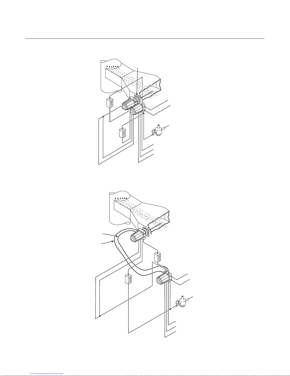
Reference Air Set and Solenoids Option with COe Zero Function
Figure 2-11 shows the piping arrangement for the OCX 8800 with
autocalibration when the COe Zero Function is used. The arrangement is
similar to Figure 2-10 except instrument air is used as the Hi O2 test gas.
Refer to Section 3 for details of this function.
Figure 2-11. Pneumatic Installation, OCX with Reference Air Set, Solenoids and Autocalibration, with
COe Zero Function
Page 45

Instruction Manual
IM-106-880, Rev 2.1
April 2017
OCX 8800
2-17
Reference Air Set, Solenoids, and Blowback Option with
COe Zero Function
Figure 2-13 shows the piping arrangement for the OCX 8800 with the
blowback and autocalibration options when the COe Zero Function is used.
The arrangement is similar to Figure 2-12 except instrument air is used as the
Hi O2 test gas. Refer to Sectio 3 for details of the function.
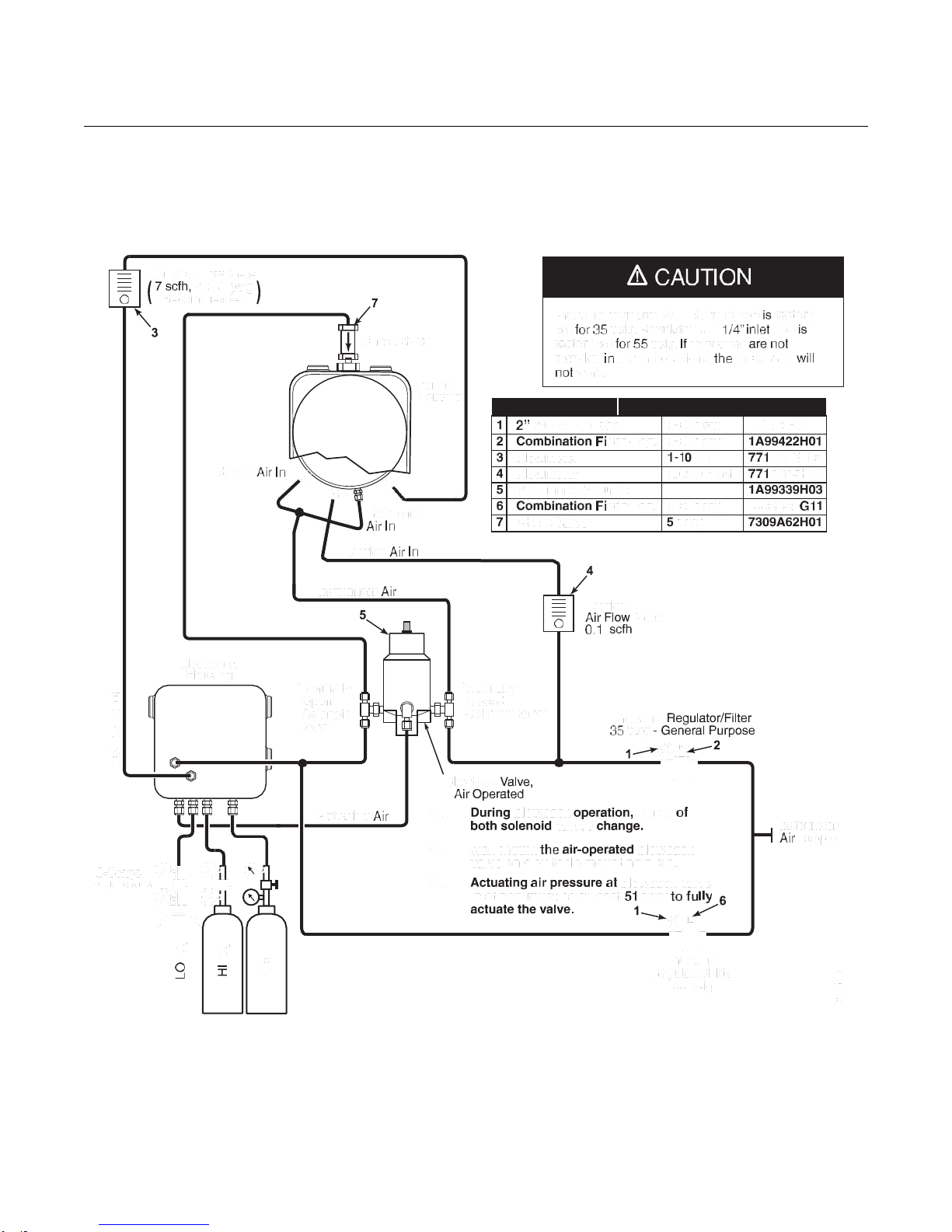
Reference Air Set, Solenoids, and Blowback Option without
COe Zero Function
Installing an OCX 8800 with the blowback option requires the addition of air
operated blowback valve, regulator and gage, and check valve.
Figure 2-12 shows the piping arrangement for the OCX 8800 with the
blowback and autocalibration options. Figure 2-14 shows the piping
arrangement for the OCX 8800 with the blowback option, but without
autocalibration (without test gas solenoids).
When the reference air set, calibration gas solenoids, and blowback options
are included with your transmitter, use the following procedure to install the
pneumatic system components.
1.
Connect the calibration gas sources according to the instructions in the
previous paragraph “Reference Air Set and Solenoids Option”, steps 2
through 5.
2.
Connect a clean, dry, instrument-quality supply of air (20.95% O2) to the
35 psig and 55 psig pressure regulators. The inlet to the 35 psig
regulator accepts a 1/8" NPT fitting. The inlet to the 55 psig regulator
accepts a 1/4" NPT fitting.
3.
See the upper leg of the instrument air supply. Connect the output of the
35 psi regulator/filter to one port of the normally-closed air-operated
solenoid valve, and to the inlet side of the dilution air flow meter.
4.
Connect the dilution air flow meter output to the DILUTION AIR inlet
fitting on the sensor housing.
5.
Install an instrument air line between the open port of the normally-open
air-operated solenoid valve and the tee fitting on the sensor housing.
6.
Connect the output of the 55 psi regulator/filter to one port of the
normally-open air-operated solenoid valve, and to the instrument air
inlet on the back of the electronics housing.
7.
Install an air line between the open port of the normally-closed
air-operated solenoid valve and the check valve inlet fitting on the
sensor housing.
8.
Install an air line between the instrument air outlet fitting on the
electronics housing and the control air inlet fitting on the air-operated
solenoid valve.
Page 46
Instruction Manual
IM-106-880, Rev 2.1
April 2017
OCX 8800
2-18
Figure 2-12. Pneumatic Installation, OCX with Reference Air Set, Solenoids, Blowback and Autocalibration,
without COe Zero Function
Page 47

Instruction Manual
IM-106-880, Rev 2.1
April 2017
OCX 8800
2-19
Figure 2-13. Pneumatic Installation, OCX with Reference Air Set, Solenoids, Blowback and Autocalibration,
with COe Zero Function
Reference Air Set, Solenoids, and Blowback Option
with COe Zero Function
Figure 2-13 shows the piping arrangement for the OCX 8800 with the
blowback and autocalibration options when COe Zero Function is used. The
arrangement is similar to Figure 2-12 except instrument air is used as the Hi
O2 test gas. Refer to Section 3 for details of this function.
Page 48

Instruction Manual
IM-106-880, Rev 2.1
April 2017
OCX 8800
2-20
CAUTION
Pressure regulator with 1/8” inlet port is factory
set for 35 psig. Regulator with 1/4” inlet port is
factory set for 55 psig. If regulators are not
installed in correct locations, the OCX 8800 will
not work.
7
Check Valve
Sensor
Housing
CAL Gas Flow Meter
7 scfh, 20-30 psig
Recommended
Eductor Air In
CAL Gas In
Reference Air In
3
2-Stage
Regulators
Dilution Air In
4
Instrument Air
5
Dilution
Air Flow Meter
0.1 scfh
Electronics
Housing
*Normally
Open
Solenoid
Valve
*Normally
Closed
Solenoid
Valve
Blowback Valve,
Air Operated
Pressure Regulator/Filter
35 psig - General Purpose
1
2
Actuating Air
*NOTE: During blowback operation, states of
both solenoid valves change.
NOTE: Wall mount the air-operated blowback
valve on a suitable mounting plate.
NOTE: Actuating air pressure at blowback valve
inlet port must be at least 51 psig to fully
Instrument
Air Supply
actuate the valve.
1
6
LO O
2
HI O
2
CO
38850005
Replacement Parts
1 2” Pressure Gage
0-60 psig
275431-03
2 Combination Filter-Reg.
0-60 psig
1A99422H01
3 Flowmeter
1-10 scfh
771B635H01
4 Flowmeter
0.05-0.5 scfh
771B635H08
5 Pneumatic Actuator
1A99339H03
6 Combination Filter/Reg.
0-60 psig
4505C21G11
7 Check Valve
5 psig
7309A62H01
Figure 2-14. Pneumatic Installation, OCX with Reference Air Set and Blowback without Autocalibration
Pressure
Regulator/Filter
55 psig
Page 49

Instruction Manual
IM-106-880, Rev 2.1
April 2017
OCX 8800
2-21
LO O
2
HI O
2
CO
39930003
Reference Air Set and Blowback Panels
An optional blowback panel is shown in Figure 1-9. Piping arrangement for
blowback panel without autocalibration without COe Zero Function is shown
in Figure 2-15. Piping arangement for blowback panel with autocalibration
without COe Zero Function is shown in Figure 2-16. Piping arrangement for
blowback panel with autocalibration with COe Zero Function is shown in
Figure 2-17.
Figure 2-15. Pneumatic Installation, Blowback Panel without Autocalibration without COe Zero Function
Check Valve
Sensor
Housing
Eductor Air In
CAL Gas In
Instrument Air
Reference Air In
Dilution Air In
Instrument
Air Supply
CAL Gas
Out
CAL Gas
In
Regulators
2-Stage
Dilution
Air Out
Instrument Air to Electronics
Blowback
Air Out
Blowback
Control Air
Instrument
Air Out
Actuating Air
Electronics
Housing
Page 50
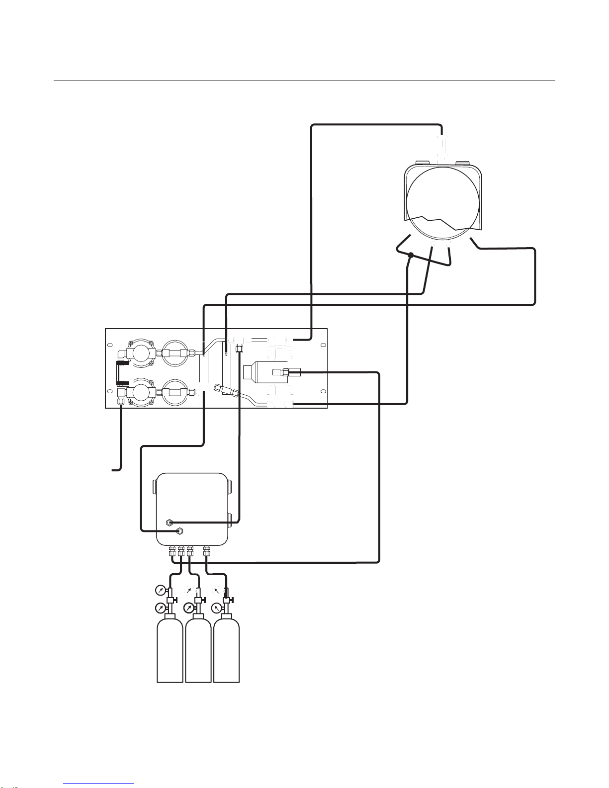
Instruction Manual
IM-106-880, Rev 2.1
April 2017
OCX 8800
2-22
LO O
2
HI O
2
CO
39930004
Figure 2-16. Pneumatic Installation, Blowback Panel with Autocalibration without COe Zero Function
Check Valve
Eductor Air In
Instrument Air
Reference Air In
Dilution Air In
Blowback
Air Out
Blowback
Control Air
Instrument
Air Out
Instrument
Air Supply
CAL Gas
Out
CAL Gas
In
Electronics
Housing
Dilution
Air Out
Instrument
Air to
Electronics
CAL Gas
Out
2-Stage
Regulators
Actuating Air
Sensor
Housing
CAL Gas In
Page 51

Instruction Manual
IM-106-880, Rev 2.1
April 2017
OCX 8800
2-23
Figure 2-17. Pneumatic Installation, Blowback Panel with Autocalibration with COe Zero Function
Page 52

Instruction Manual
IM-106-880, Rev 2.1
April 2017
OCX 8800
2-24
Upon completing installation, make sure that the OCX 8800 is turned on and operating prior
to firing up the combustion process. Damage can result from having a cold OCX 8800
exposed to the process gases.
If ducts will be washed down during outages, make sure to power down the OCX 8800 units
and remove them from the wash area.
INITIAL STARTUP Observe the following Caution and Note. Refer to Section 3: Configuration
and Startup, for OCX 8800 startup information.
NOTE
During outages, and whenever possible, leave OCX 8800 units running to
prevent condensation and premature aging from thermal cycling.
Page 53

Instruction Manual
IM-106-880, Rev 2.1
Install all protective equipment covers and safety ground leads after installation. Failure to
install covers and ground leads could result in serious injury or death.
Make sure that the OCX 8800 is turned on and operating prior to firing up the combustion
process. Damage can result from having a cold OCX 8800 exposed to the process gases.
April 2017
Section 3 Configuration and Startup
Verify Installation . . . . . . . . . . . . . . . . . . . . . . . . . . . . . . . . page 3-1
Initial Power Up . . . . . . . . . . . . . . . . . . . . . . . . . . . . . . . . . . page 3-4
Set Test Gas Values . . . . . . . . . . . . . . . . . . . . . . . . . . . . . . page 3-4
Calibration Solenoids . . . . . . . . . . . . . . . . . . . . . . . . . . . . . page 3-5
Blowback Feature . . . . . . . . . . . . . . . . . . . . . . . . . . . . . . . . page 3-6
Calibration Verify Feature . . . . . . . . . . . . . . . . . . . . . . . . . page 3-7
Calibration Tolerance Feature . . . . . . . . . . . . . . . . . . . . . . page 3-9
COe PURGE / ZERO FEATURE . . . . . . . . . . . . . . . . . . . . . page 3-10
OCX 8800 Reset Procedure . . . . . . . . . . . . . . . . . . . . . . . . page 3-12
OCX 8800
VERIFY INSTALLATION Ensure the OCX 8800 is installed correctly. Verify mechanical installation and
all electrical and pneumatic connections. Refer to Section 2, Installation.
NOTE
During outages, and whenever possible, leave all OCX 8800 units running to
prevent condensation and premature aging from thermal cycling.
Page 54

Instruction Manual
IM-106-880, Rev 2.1
April 2017
OCX 8800
3-2
Remove power from the OCX 8800 before changing defaults. If defaults are changed under
power, damage to the electronics may occur.
Verify Configuration - HART Electronics
There are three switches on the microprocessor board which are user
configurable for the OCX 8800 with HART electronics (Figure 3-1). SW1
determines if the O2 4-20 mA signal is internally or externally powered. SW2
determines if the COe 4-20 mA signal is internally or externally powered. SW3
sets the rail limits for the O2 and COe 4-20 mA signals and configures the
sample line heater control circuit. All switches are accessible through holes in
the electronics box.
Figure 3-1. OCX 8800 Defaults - HART Electronics
Page 55

Instruction Manual
IM-106-880, Rev 2.1
April 2017
OCX 8800
3-3
Remove power from the OCX 8800 before changing defaults. If defaults are changed under
power, damage to the electronics may occur.
Verify that the following switch settings are correct for your OCX 8800
installation:
SW1 The two settings are internally or externally powering the O2 4-20
mA signal. The factory setting is for the O2 4-20 mA signal to be internally
powered.
SW2 The two settings are internally or externally powering the COe 4-20
mA signal. The factory setting is for the COe 4-20 mA signal to be
internally powered.
SW3 The factory sets this switch as follows:
•
Position 1 determines the O2 4-20 mA signal rail limit. The settings are
high, 21.1 mA, or low, 3.5 mA. The factory setting is low, 3.5 mA.
•
Position 2 determines the COe 4-20 mA signal rail limit. The settings
are high, 21.1 mA, or low, 3.5 mA. The factory setting is high, 21.1 mA.
•
Positions 3 and 4 must be set as shown for proper software control of
the device heaters.
Verify Configuration - Fieldbus Electronics
There is one switch on the microprocessor board which must be set for the
OCX 8800 with fieldbus electronics (Figure 3-2). SW3 configures the sample
line heater control circuit. This switch is accessible through holes in the
electronics box.
Verify that the following switch settings are correct for your OCX 8800
installation:
SW3 The factory sets this switch as follows:
•
Position 1 not used.
•
Position 2 not used.
•
Positions 3 and 4 must be set as shown for proper software control of
the device heaters.
Page 56
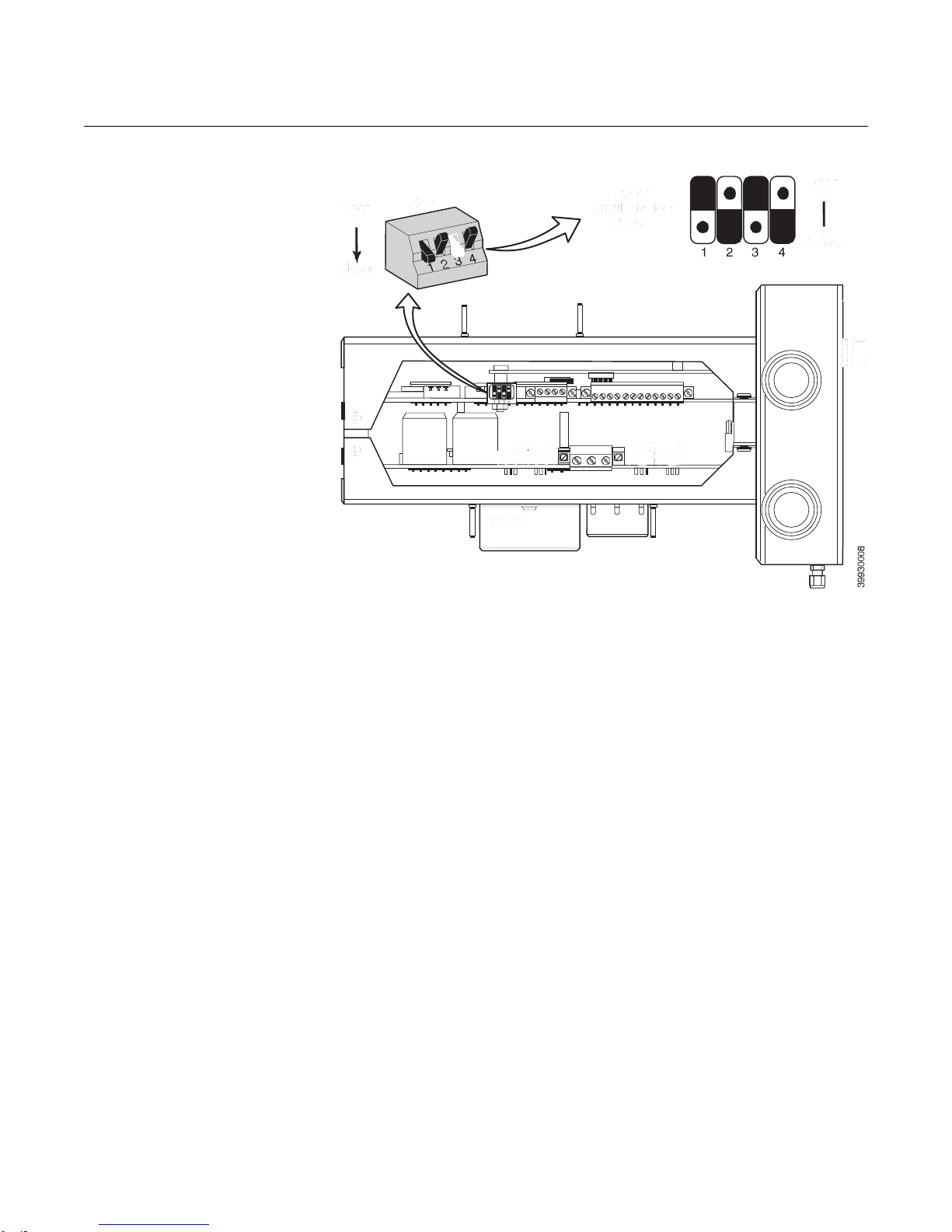
Instruction Manual
IM-106-880, Rev 2.1
April 2017
OCX 8800
3-4
Figure 3-2. OCX 8800 Defaults Fieldbus Electronics
INITIAL POWER UP Allow adequate time (approximately 60 minutes) for the heaters to begin
operation and for the OCX 8800 to reach normal operating temperature on
power up. Normal operating temperature for the O2 cell is 736°C. Normal
operating temperature for the combustibles cell is 300°C. The normal sample
line temperature is 170°C. During this time the eductor air solenoid will remain
closed so no sample is pulled through the analyzer. When the OCX reaches
operating temperature the solenoid will energize, eductor air will begin to flow,
and the unit will begin normal operation.
SET TEST GAS VALUES Use Field Communicator or the optional LOI to set test gas values for
calibration. Refer to Section 4, Using the LOI or Section 6, Field
Communicator for more information.
Setting Test Gas Values with the Field Communicator
1.
Use the 375 Field Communicator software to access the HART menu.
2.
From the DETAILED SETUP menu, select CAL SETUP.
3.
From the CAL SETUP menu, select O2 CAL PARAMS or COe CAL
PARAMS.
4.
From O2 CAL PARAMS, select O2 HIGH GAS. Enter the percent O
used for the high O2 test gas.
5.
From O2 CAL PARAMS, select O2 LOW GAS. Enter the percent O
used for the low O2 test gas.
6.
From COe CAL PARAMS, select COe Test Gas. Enter the CO
concentration (ppm) used for COe test gas.
2
2
Page 57

Instruction Manual
IM-106-880, Rev 2.1
April 2017
OCX 8800
3-5
Setting Test Gas Values with Fieldbus Communicator
1.
Use the 375 Field Communicator software to access the Fieldbus menu.
2.
From the TRANSDUCER menu, select O2 CAL.
3.
From O2 CAL menu select O2 CAL SETUP.
4.
From O2 CAL SETUP, select O2 HIGH GAS. Enter the percent O2 used
for the high test gas.
5.
From O2 CAL SETUP, select O2 LOW GAS. Enter the percent O2 used
for the low test gas
6.
From the TRANSDUCER menu select COe CAL SETUP.
7.
From COe CAL SETUP, select COe Test Gas. Enter the CO
concentration (ppm) used for the COe Test Gas.
Setting Test Gas Values with the LOI
1.
Use the "Z" pattern to enter the LOI menu tree.
2.
From the SYSTEM menu, select Calib Setup.
3.
From Calib Setup, select O2 High Gas %. Enter the percent O2 used
for the high O2 test gas.
4.
Select the down arrow and the next selection will be O2 Low Gas %.
Enter the percent O2 used for the low O2 test gas.
5.
Select the down arrow several times to display COe Test Gas. Enter the
CO concentration (ppm) used for COe test gas.
CALIBRATION
SOLENOIDS
The OCX 8800 can be provided with optional calibration solenoids for the
purpose of performing autocalibration. The solenoids are controlled by the
OCX 8800 software and automatically switch in the proper calibration gas
during the calibration cycle.
An OCX 8800 shipped from the factory with calibration solenoids must be
configured before autocalibration can be implemented. This same process
must be performed any time a replacement card stack is installed.
Configuring the Calibration Solenoids
with the Field Communicator - HART
1.
Use the 375 Field Communicator to access the HART menu.
2.
From the DETAILED SETUP menu, select CAL SETUP.
3.
From the CAL SETUP menu, select O2 CAL PARAMS/COe CAL
PARAMS.
4.
From the O2 CAL PARAMS/COe CAL PARAMS, select Solenoids.
Select Yes to enable the solenoids.
Configuring the Calibration Solenoids with the Field Communicator Fieldbus
1.
Use the 375 Field Communicator to access the Fieldbus menu.
2.
From the TRANSDUCER block menu, select O2 CAL/COE CAL.
3.
From the O2 CAL/COE CAL menu, select O2 CAL SETUP/COE CAL
SETUP.
4.
From the O2 CAL SETUP/COE CAL SETUP, select Solenoids. Select
Present to enable the solenoids.
Page 58

Instruction Manual
IM-106-880, Rev 2.1
April 2017
OCX 8800
3-6
Configuring the Calibration Solenoids with the LOI
1.
Use the "Z" pattern to enter the LOI menu tree.
2.
From the SYSTEM menu, select Calib Setup.
3.
From the Calib Setup menu, select Use Solenoids. Select Yes to
enable the solenoids.
BLOWBACK FEATURE The blowback feature blows instrument air back through the center of the
internal filter and out the sample tube of the probe. This removes built up dirt
and particulate from the internal filter, sample line and any optional in-situ filter
on the end of the sample tube. The blowback feature is normally used in
systems that have heavy particulate in the process stream.
The blowback feature requires the optional blowback hardware to be properly
installed external to the OCX 8800. See Section 2, Pneumatic Installation, for
details.
An OCX 8800 shipped from the factory must be configured before blowback
can be implemented. This same process must be performed any time a
replacement card stack is installed.
Configuring Blowback with the Field Communicator - HART
1.
Use the 375 Field Communicator or AMS software to access the HART
menu.
2.
From the DETAILED SETUP menu, select INPUT/OUTPUT.
3.
From the INPUT/OUTPUT menu, select BLOWBACK.
4.
From the BLOWBACK, select BlBk Enabled. Select Yes to enable
blowback. Also set the following parameters:
BlBk Intrvl - Length of time between blowback events (60 minutes
recommended).
BlBk Period - Length of time blowback is activated (5 seconds
recommended).
BlBk Purge Time - Length of time after blowback is complete before
oxygem/combustibles readings are considered valid (Set as required by
the application).
5.
Manually initiate blowback from DIAG/SERVICE, then BLOW BACK,
When select BLOWBACK.Configuring Blowback with the Field
Communicator - Fieldbus
1.
Use the 375 Field Communicator or AMS software to access the
Fieldbus menu.
2.
From the TRANSDUCER block menu, select Alarm Relay/Blowback.
3.
From the Alarm Relay/Blowback menu, select Blowback.
4.
From the Blowback menu, select Blowback Enabled. Also set the
following parameters:
Blowback Interval - Length of time between blowback events (60
minutes recommended).
Blowback Period - Length of time blowback is activated (5 seconds
recommended).
Page 59

Instruction Manual
IM-106-880, Rev 2.1
April 2017
OCX 8800
3-7
During the Calibration Verify function the analog output signals will track the oxygen and
combustibles readings. To avoid a potentially dangerous operating condition, the OCX
8800 must be removed from the automatic combustion control loop before performing the
Calibration Verify procedure.
Blowback Purge Time - Length of time after blowback is complete
before oxygem/combustibles readings are considered valid (Set as
required by the application).
Initiate Blowback - Initiates a blow back event manually.
Configuring Blowback with the LOI
1.
Use the "Z" pattern to enter the LOI menu tree.
2.
From the SYSTEM menu, select Blow Back.
3.
From the Blow Back menu, select Blow Bk Enable. Select Yes to
enable blowback. Also set the following parameters:
Blow Bk Intrvl - Length of time between blowback events. Range is 0
to 32,000 minutes. Default is 60 minutes. 60 minutes is recommended.
Blow Bk Period - Length of time blowback in activated. Range is 1 to 5
seconds. Default is 2 seconds. 5 seconds is recommended.
Blow Bk Purge - Length of time after blowback is complete before
oxygem/combustibles readings are considered valid. Range is 0 to 500
seconds. Default is 88 seconds. Set as required by the application.
CALIBRATION VERIFY
FEATURE
Force Blow Bk - Initiates a blow back event manually.
The calibration verify feature flows one or more calibration gases to verify the
analyzer is reading correctly. The calibration verify feature flows each
calibration gas on demand to verify calibration, but does not change the slope
or constant of the current calibration. This function uses the same gas flow
and purge times from the basic calibration setup.
The calibration verify feature is only valid if the OCX 8800 is supplied with
calibration solenoids and the solenoids have been activated.
Performing a Calibration Verify with the Field Communicator - HART
1.
Use the 375 Field Communicator or AMS software to access the HART
menu.
2.
From the DEVICE SETUP menu, select DIAG/SERVICE.
3.
From the DIAG/SERVICE menu, select CALIBRATION.
4.
From the CALIBRATION, select CAL VERIFY. Select Verify
Calibration. From this menu, select the functions as follows:
Flow High O2 Gas - Flows the high O2 test gas for the time specified in
the calibration setup.
Flow Low O2 Gas - Flows the low O2 test gas for the time specified in
the calibration setup.
Flow High COe Gas - Flows the COe test gas for the time specified in
the calibration setup.
Page 60

Instruction Manual
IM-106-880, Rev 2.1
April 2017
OCX 8800
3-8
Purge Gas - Initiates a delay for the specified purge time before
oxygen/combustibles readings are considered valid.
NOTE:
A Purge will automatically follow a gas flow.
Performing a Calibration Verify with the Field Communicator - Fieldbus
1.
Use the 375 Field Communicator or AMS software to access the
Fieldbus menu.
2.
From the TRANSDUCER block menu, select METHODS.
3.
Set the Mode to OOS (Out of Service) before starting the Calibration
Verify process.
4.
From the METHODS menu, select OCX Cal Verify. From this menu,
select the functions as follows:
Flow High O2 Gas - Flows the high O2 test gas for the time specified in
the calibration setup.
Flow Low O2 Gas - Flows the low O2 test gas for the time specified in
the calibration setup.
Flow High COe Gas - Flows the COe test gas for the time specified in
the calibration setup.
Purge Gas - Initiates a delay for the specified purge time before
oxygen/combustibles readings are considered valid.
NOTE:
A Purge will automatically follow a gas flow.
Performing a Calibration Verify with the LOI
1.
Use the "Z" pattern to enter the LOI menu tree.
2.
From the CALIBRATION menu, select Cal Verify.
3.
From the Cal Verify menu, select the functions as follows:
Flow High Gas - Flows the high O2 test gas for the time specified in the
calibration setup.
Flow Low Gas - Flows the low O2 test gas for the time specified in the
calibration setup.
Flow COe Gas - Flows the COe test gas for the time specified in the
calibration setup.
Purge - Initiates a delay for the specified purge time before
oxygen/combustibles readings are considered valid.
NOTE:
A Purge will automatically follow a gas flow.
Page 61

Instruction Manual
IM-106-880, Rev 2.1
April 2017
OCX 8800
3-9
CALIBRATION
TOLERANCE FEATURE
The calibration tolerance feature provides a mechanism to fail a calibration if
the calibration measurement does not fall within a specific tolerance of the
test gas value. The tolerance is preset within the OCX 8800 software and is
not user adjustable. The tolerance is different between the oxygen and
combustibles test gases. For oxygen, the calibration will fail if the measured
value differs by more than ±10% of the configured value. For combustibles,
the calibration will fail if the measured value differs by more than ±30% of the
configured value.
An OCX 8800 shipped from the factory must be configured before the
calibration tolerance feature can be implemented. This same process must
be performed any time a replacement card stack is installed.
Configuring the Calibration Tolerance Feature with the Field
Communicator - HART
1.
Use the 375 Field Communicator or AMS software to access the HART
menu.
2.
From the DETAILED SETUP menu, select CAL SETUP.
3.
From the CAL SETUP menu, select O2 CAL PARAMS.
4.
To enable the calibration tolerance feature for the oxygen calibration,
from the O2 CAL PARAMS, select O2 Tol Check. Select On to enable
the calibration tolerance feature.
5.
Back out to the CAL SETUP menu, select COe CAL PARAMS.
6.
To enable the calibration tolerance feature for the combustibles
calibration, from the COe CAL PARAMS, select COe Tol Check.
Select On to enable the calibration tolerance feature.
Configuring the Calibration Tolerance Feature with the Field
Communicator - Fieldbus
1.
Use the 375 Field Communicator or AMS software to access the
Fieldbus menu.
2.
From the TRANSDUCER block menu, select O2 CAL/COe CAL.
3.
From the O2 CAL/COe CAL menu, select O2 CAL SETUP/COe CAL
SETUP.
4.
From the O2 CAL SETUP/COe CAL SETUP menu, select O2
Tolerance Check/COe Tolerance Check. Select Yes to enable the
calibration tolerance feature.
Configuring the Calibration Tolerance Feature with the LOI
1.
Use the "Z" pattern to enter the LOI menu tree.
2.
From the SYSTEM menu, select Calib Setup.
3.
From the Calib Setup menu, select the following:
O2 Tol Check - Select Yes to enable the calibration tolerance feature
for the oxygen calibration.
Comb Tol Check - Select Yes to enable the calibration tolerance
feature for the combustibles calibration.
Page 62

Instruction Manual
IM-106-880, Rev 2.1
April 2017
OCX 8800
3-10
During the COe Zero Function the analog output signals may track the oxygen and
combustibles readings if configured to do so. To avoid a potentially dangerous operating
condition, the OCX 8800 must be removed from the automatic combustion control loop
before performing the COe Zero Function procedure.
At the completion of the COe Zero Function, the COe analog output signal will change if the
Zero Update parameter is set to "Yes".
COe PURGE / ZERO
FEATURE
This feature provides a way to periodically flood the COe sensor with air to
perform two functions; a) provide additional oxygen to help burn off any
combustible residue from the COe sensor, and b) allow for optional
adjustment of the COe calibration constant. If the OCX8800 is configured to
update the COe calibration constant, only the constant is updated. The COe
calibration slope is not affected. To update both the constant and slope a full
calibration must take place.
The feature uses the calibration solenoid that is also used for high O2 test gas
and COe zero gas. For the feature to work properly, instrument air is used as
the high O2 test gas. This also requires the high O2 test gas value to be set
at 20.95%.
As an option, a two way valve may be installed to switch the high O2 test gas
between the normal calibration gas and instrument air. This allows the OCX
8800 to use a specified calibration gas for calibration, then instrument air for
the COe zero feature. Switching between the two gases must be manually
coordinated between scheduled calibrations and COe zero events.
When the COe zero feature is used, special pneumatic connections are
required. See Section 2, Pneumatic Installation, for details.
The COe zero feature is only valid if the OCX 8800 is supplied with calibration
solenoids and the solenoids have been activated.
An OCX 8800 shipped from the factory must be configured before the COe
zero feature can be implemented. This same process must be performed any
time a replacement card stack is installed.
Configuring the COe Zero Feature with the Field Communicator - HART
1.
Use the 375 Field Communicator or AMS software to access the HART
menu.
2.
From the DETAILED SETUP menu, select INPUT/OUTPUT.
3.
From the INPUT/OUTPUT menu, select COE ZERO.
4.
From the COE ZERO menu, select the functions as follows:
Zero Enabled - Select "Yes" or "No" to enable or disable this feature.
Zero Intrvl - Length of time between COe zero events. Range is 60 to
480 minutes. Default is 60 minutes.
Page 63

Instruction Manual
IM-106-880, Rev 2.1
April 2017
OCX 8800
3-11
Zero Flow - Length of time COe zero gas flows. Range is 120 to 600
seconds. Default is 120 seconds.
Zero Purge - Length of time after COe zero is complete before
oxygen/combustibles readings are considered valid. Range is 60 to
180 seconds. Default is 60 seconds. Total duration of this function is
flow time plus purge time.
Zero Tracks - Determines if the analog output signals track or hold
during the function. Valid choices are None, Both, COe, and O2.
Zero Update - Determines if the COe calibration constant is updated at
the end of the function. Valid choices are Yes and No. A Yes choice will
cause the COe calibration constant to update.
Configuring the Calibration Tolerance Feature with the Field
Communicator - Fieldbus
1.
Use the 375 Field Communicator or AMS software to access the
Fieldbus menu.
2.
From the TRANSDUCER block menu, select COe ZERO.
3.
From the COe ZERO menu, select the functions as follows:
COe Zero Enable - Select "Yes" or "No" to enable or disable this
feature.
COe Zero Interval - Length of time between COe zero events. Range
is 60 to 480 minutes. Default is 60 minutes.
COe Zero Duration - Length of time COe zero gas flows. Range is 120
to 600 seconds. Default is 120 seconds.
COe Zero Purge Time - Length of time after COe zero is complete
before oxygen/combustibles readings are considered valid. Range is
60 to 180 seconds. Default is 60 seconds. Total duration of this
function is flow time plus purge time.
COe Zero Output Track - Determines if the analog output signals track
or hold during the function. Valid choices are None, Both, COe, and O2.
COe Zero Update - Determines if the COe calibration constant is
updated at the end of the function. Valid choices are Yes and No. A
Yes choice will cause the COe calibration constant to update.
Configuring the COe Zero Feature with the LOI
1.
Use the "Z" pattern to enter the LOI menu tree.
2.
From the SYSTEM menu, select Input/Output.
3.
From the Input/Output menu, select COe Zero. Select the functions as
follows:
COe Zero Enable - Select "Yes" or "No" to enable or disable this
feature.
COe Zero Intrvl - Length of time between COe zero events. Range is
60 to 480 minutes. Default is 60 minutes.
COe Zero Flow - Length of time COe zero gas flows. Range is 120 to
600 seconds. Default is 120 seconds.
Page 64

Instruction Manual
IM-106-880, Rev 2.1
April 2017
OCX 8800
3-12
COe Zero Purge - Length of time after COe zero is complete before
oxygen/combustibles readings are considered valid. Range is 60 to 180
seconds. Default is 60 seconds. Total duration of this function is flow
time plus purge time.
COe Zero Tracks - Determines if the analog output signals track or hold
during the function. Valid choices are None, Both, COe, and O2.
COe Zero Update - Determines if the COe calibration constant is
updated at the end of the function. Valid choices are Yes and No. A Yes
choice will cause the COe calibration constant to update.
OCX 8800 RESET
PROCEDURE
Whenever you correct an equipment alarm or fault condition, the OCX 8800
will either revert to normal operation or continue to indicate an alarm status
condition. If the equipment does not revert to normal operation when a fault
condition is cleared, or if instructed to do so in Section 8, Troubleshooting,
use the following procedure to reset the OCX 8800.
OCX Reset with the LOI
1.
Use the "Z" pattern to enter the LOI menu tree. (Refer to Section 4,
Using the LOI).
2.
Select the SYSTEM submenu.
3.
From the SYSTEM submenu, select the Status submenu.
4.
From the Status submenu, select Reset Device. The OCX 8800 will
reset and the LOI will revert to the normal operation display.
OCX Reset with the Field Communicator
Remove the OCX 8800 from the process loop and recycle power.
Page 65

Instruction Manual
IM-106-880, Rev 2.1
April 2017
OCX 8800
37390027
Section 4 Using the LOI
Overview . . . . . . . . . . . . . . . . . . . . . . . . . . . . . . . . . . . . . . . page 4-1
Display Orientation . . . . . . . . . . . . . . . . . . . . . . . . . . . . . . . page 4-1
LOI Controls . . . . . . . . . . . . . . . . . . . . . . . . . . . . . . . . . . . . page 4-2
LOI Menu Tree . . . . . . . . . . . . . . . . . . . . . . . . . . . . . . . . . . . page 4-4
OVERVIEW This section describes the installation and operation of the LOI module in the
OCX 8800.
DISPLAY ORIENTATION The LOI module mounts to a connector on the LOI board. The board is
installed on the end of the electronics stack in the electronics housing,
Figure 4-1. There are four mating connectors on the back of the LOI module
that allow the LOI to be oriented as desired by the user.
Figure 4-1. LOI Components
Mounting
Electronics Housing
(Cover Removed)
Electronics Stack
LOI Connector
LOI Board
LOI Module
Page 66

Instruction Manual
IM-106-880, Rev 2.1
April 2017
OCX 8800
4-2
LOI CONTROLS
Overview The LOI, shown in Figure 4-2, utilizes a bright blue gas-fluorescent display.
Intensity is adjustable. There is an Infrared LED source and a detector for
each key. The detectors can detect a finger placed above the button through
the glass window. There is no need to open the instrument in bad weather or
in hazardous areas in order to access the electronics.
It should be noted that the OCX 8800 also uses HART or FOUNDATION
Fieldbus communications, permitting access to all instrument functionality
anywhere the digital O2 signal terminates via a model 375 Field
communicator.
Figure 4-2. LOI Assembly
Touch
Selection
Arrow
(Enter key)
E
Display
Window
Confirmation
LED
Analytical
Selection
Arrow
LK
AL
Lockout
Notation
Status
Code
LOI Key Functions The gray (top left) key will move one level higher in the menu structure. When
Selection
Arrows
37390042
entering parameter values (numbers), this key moves the cursor to the left.
The left-pointing key also doubles as an Enter key, used after the digits of a
parameter value are entered, and the cursor is moved to its left-most position.
When the Enter key is touched, the new parameter value, if accepted, will
appear in the top line of the display.
The blue (bottom left) key acts as a selector when choosing from among
several menu items. This right-pointing key also will move the cursor to the
right when entering the digits of a new parameter value.
The up and down-pointing keys are used to increment up and down when
selecting from a vertical list of menu items. These keys are also used for
incrementing values up and down for new data input.
Page 67

Instruction Manual
IM-106-880, Rev 2.1
April 2017
OCX 8800
4-3
1 2
E
Analytical
3
4
CODE DESCRIPTION
37390057
Figure 4-3. ‘Z’ Pattern Entry
Lockout
The LOI has a lockout feature that prevents nuisance actuation by someone
brushing against the glass window, raindrops, dirt, insects, etc. This lockout
mode is automatically established when no buttons are pushed for 30
seconds (default). This countdown to lockout is configurable.
In order to unlock the display, input a "Z" pattern (Figure 4-3). First, touch the
top left (gray) Enter key. Next, touch the top right key, followed by the bottom
left key and the bottom right key. The LK notation in the upper right corner of
the display will disappear. Touch the Enter key once more to enter into the
menu structure. Whenever a key is touched additional time to lockout is
provided, so that the lockout feature does not become a nuisance. This
additional revert time is one hour (default) and is also user configurable.
NOTE
Always clean dust and soil away from the LOI screen each time the LOI is
used. Excessive dust can prevent the LOI from entering lockout. This
condition can cause uncommanded operations to occur.
LOI Status Codes The LOI display shows a status code in the lower right hand corner of the
Table 4-1. LOI Status Codes
display. There are nine status codes to indicate the existing status of the
device during operation. The status code descriptions are shown in Table 4-1.
AL Alarm - The device is in a recoverable alarm state.
BL Blowback - A blowback cycle is active.
CA Calibration - A calibration cycle is active.
CV Calibration Verify - A calibration verify task is in progress.
NM Normal - The device is in a normal operating mode.
PO
SF
ST
WU Warm Up - The device heaters are ramping up to operating temperature.
CZ COe Zero - The COe Zero cycle is active.
Power On - A system level initialization sequence is active. This will continue for
several seconds.
System Fault - The device is in a non-recoverable alarm condition. The unit
must be reset or power must be cycled off and on to resume operation.
Stabilize - The device heater control is stabilizing (after warm up). Sensors are
warming up to operating temperature.
Page 68

Instruction Manual
IM-106-880, Rev 2.1
April 2017
OCX 8800
4-4
LOI MENU TREE This section consists of a menu tree for the LOI on the OCX 8800, Figure 4-4.
This menu is specific to the OCX 8800.
First Column Submenus
From the operating display (O2% and COe ppm), the left-pointing Enter key is
the only option to move into the first column submenus of the LOI menu tree.
The first column contains three submenus: SENSOR DATA, Figure 4-4 sheet
1 of 4, CALIBRATION, sheet 2 of 4, and SYSTEM, sheets 3 and 4 of 4. From
the operating display, SENSOR DATA is displayed when the right-pointing
key is selected. Use the up or down-pointing key to move to the other first
column submenus.
Second Column Submenus
From the first column submenus, selecting the right-pointing key moves the
display into the second column submenus. The up and down-pointing keys
allow the display to move to the second column submenus of the first column
submenu selected. The left-pointing key moves the display back to the first
column submenu.
Figure 4-4. LOI Menu Tree
(Sheet 1 of 4)
Third and Fourth Column Submenus
From the second column submenus, selecting the right-pointing key moves
the display into the third column submenus. The third column submenu may
be another menu or a list of parameters. The up- and down-pointing keys
allow the display to move to the different parameters or menus. The third or
fourth column submenu may be a parameter list. When a parameter list is
displayed, the cursor will blink. The up- and down-pointing keys select the
value for the parameter displayed.
Page 69

Instruction Manual
IM-106-880, Rev 2.1
April 2017
OCX 8800
4-5
Figure 4-4. LOI Menu Tree
(Sheet 2 of 4)
(CONTINUED FROM
SHEET 1)
CALIBRATION
(CONTINUED ON
SHEET 3)
Cal
Control
Abort Cal
Start Cal
O2
Start Cal
COe
Start Cal
Both
Apply Lo O2 Gas
Hit E when ready
Flow O2 Lo _____s
______% _____mV
Read O2 Lo _____s
______% _____mV
Apply Hi O2 Gas
Hit E when ready
Flow O2 Hi _____s
______% _____mV
Read O2 Hi _____s
______% _____mV
Hit E when ready
Purge _____s
Apply Lo COe Gas
Hit E when ready
Flow COe Lo _____s
______% _____mV
Read COe Lo _____s
______% _____mV
Apply Hi COe Gas
Hit E when ready
Flow COe Hi _____s
______% _____mV
Read COe Hi _____s
______% _____mV
Hit E when ready
Purge _____s
Apply Lo O2 Gas
Hit E when ready
Flow O2 Lo _____s
______% _____mV
Read O2 Lo _____s
______% _____mV
Apply Hi O2 Gas
Hit E when ready
Flow O2 Hi _____s
______% _____mV
Read O2 Hi _____s
______% _____mV
Hit E when ready
Purge _____s
Flow COe Hi _____s
______% _____mV
Read COe Hi _____s
______% _____mV
Hit E when ready
Purge _____s
Cal
Constants
Cal
Status
Cal
Verify
Current
Calib
Prev
Calib
Falied
Calib
Calib Result
Calib Step
Calib Time
Next O2 Cal
Next COe Cal
Flow High Gas
Flow Low Gas
Flow COe Gas
Purge
Status
O2 Constant _____mV
O2 Sensor R _____ohm
COe Slope _____ppm/mV
COe Constant _____mV
Pre O2 Slope _____mV/D
Pre O2 Const _____mV
Pre O2 Sensor R _____ohm
Pre COe Slope _____ppm/mV
Pre COe Const _____mV
Bad O2 Slope _____mV/D
Bad O2 Const _____mV
Bad COe Slope _____ppm/mV
Bad COe Const _____mV
_O2 Slope
NOTE: “Hit E when ready” is displayed during
semi-automatic calibration only (when
Calib Setup value Use Solenoids = n).
37390015
Page 70

Instruction Manual
IM-106-880, Rev 2.1
April 2017
OCX 8800
4-6
Figure 4-4. LOI Menu Tree
(Sheet 3 of 4)
Page 71
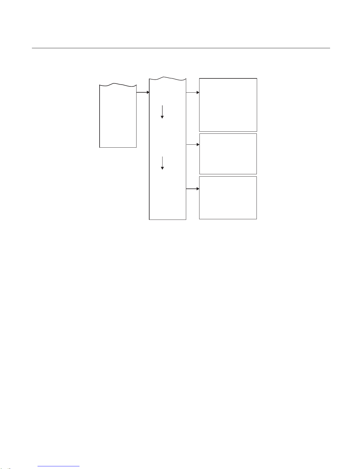
Instruction Manual
IM-106-880, Rev 2.1
April 2017
OCX 8800
4-7
Figure 4-4. LOI Menu Tree
(Sheet 4 of 4)
(CONTINUED FROM
SHEET 3)
SYSTEM
Parameters
Software
Status
O2 Slope ___ mV/D
O2 Constant ___ mV
O2 T90 Time ___ seconds
COe Slope ___ ppm/ohm
COe Constant ___ ohm
COe T90 Time ___ seconds
LockoutTime ___ seconds
Revert Time ___ minutes
Luminance
PCDC Enable ___ Y/N
PCNC Enable ___ Y/N
Version
Checksum
Build Number
Build Date
Restart Count
SW Err File
SW Err Line
SW Err Number
Alarms
CPLD Registers
Line Frequency
Line Voltage
PCD Counter
PCN Counter
Reset Device
Sensor Housing
Serial Number
___ %
37390056
Page 72

Instruction Manual
IM-106-880, Rev 2.1
April 2017
OCX 8800
4-8
Page 73

Instruction Manual
IM-106-880, Rev 2.1
April 2017
OCX 8800
Section 5 Calibration
Overview . . . . . . . . . . . . . . . . . . . . . . . . . . . . . . . . . . . . . . . page 5-1
Fully Automatic Calibration . . . . . . . . . . . . . . . . . . . . . . . . page 5-1
Operator - Initiated Autocalibration . . . . . . . . . . . . . . . . . page 5-3
Manual Calibration . . . . . . . . . . . . . . . . . . . . . . . . . . . . . . . page 5-4
D/A Trim Procedures - LOI . . . . . . . . . . . . . . . . . . . . . . . . . page 5-12
D/A Trim Procedures - HART . . . . . . . . . . . . . . . . . . . . . . . page 5-14
OVERVIEW During a calibration, two calibration gases with known O
one calibration gas with a known COe concentration are applied to the OCX
8800. Slope and constant values are calculated to determine if the OCX 8800
is correctly measuring net concentrations of O2 and combustibles in the
industrial process.
Before calibrating the OCX 8800, verify that the calibration gas parameters
are correct by setting the test gas values used when calibrating the unit. Refer
to Section 3, Configuration and Startup.
There are three calibration methods available to the OCX 8800; automatic,
operator-initiated automatic, and manual. Calibration commands and menus
can be accessed by 375 Field Communicator or by the optional LOI.
concentrations and
2
FULLY AUTOMATIC
CALIBRATION
If the OCX 8800 is equipped with calibration solenoids, the unit can be
programmed to automatically calibrate without any operator action. Refer to
the following paragraphs for using the LOI or 375 Field Communicator to set
up the OCX 8800 for fully automatic calibration.
Autocalibration Setup using the optional LOI
Use the following procedure to set up the OCX 8800 for automatic calibration.
If necessary, use the LOI menu tree in Figure 4-4 for reference. The unit must
be equipped with calibration solenoids to use automatic calibration.
NOTE
Automatic calibration is only available on units equipped with calibration
solenoids.
1.
From the operating display use the right-pointing key to select SYSTEM
first column submenu.
2.
From the SYSTEM first column submenu, use the right-pointing key to
select the Calib Setup second column submenu.
3.
From the Calib Setup second column submenu, use the right-pointing
key to select the third column parameter list.
Page 74

Instruction Manual
IM-106-880, Rev 2.1
April 2017
OCX 8800
5-2
When setting automatic calibration times, CalIntrvl and NxtCalTm should be set so that O
2
and COe are NOT calibrated simultaneously.
4.
Scroll down to the last item Use Solenoids. If the unit is equipped with
calibration solenoids and timed automatic calibration is desired, select
Yes.
5.
Use the up-pointing key to select the item O2 Out Tracks. Select Yes or
No to determine if updates to the O2 lock value will take place.
6.
Use the down-pointing key to select the item COe Out Tracks. Select
Yes or No to define if updates to the COe lock value will take place.
7.
Use the down-pointing key to select the item O2 Cal Interval. Enter the
amount of time in days and hours that is desired between automatic
calibrations.
8.
Use the down-pointing key to select the next item O2 Next Cal. Enter
the amount of time in hours until the next automatic calibration. Select
the left-pointing key three times to move back to the LOI operating
display.
Autocalibration Setup using the Field Communicator - HART
NOTE
Automatic calibration is only available on units equipped with calibration
solenoids.
Use the following procedure to specify a time interval (in hours) at which the
OCX 8800 will automatically calibrate.
1.
From the DEVICE SETUP screen, select DETAILED SETUP.
2.
From the DETAILED SETUP screen, select CAL SETUP, then select
O2 CAL PARAMS or COE CAL PARAMS.
3.
If the unit is equipped with calibration solenoids and timed automatic
calibrations are desired, select Solenoids, then select Yes. Select No to
disable the calibration solenoids.
4.
Select O2 Cal Intrvl (O2 calibration interval) and enter the desired time
in hours between automatic O2 calibrations. Select COE Cal Intrvl and
enter the desired time between automatic COe calibrations. To disable
automatic calibration for O2 and COe, enter 0 for both Cal Intrvl
parameters.
5.
If desired, the O2 Next Cal Time and the COe Next Cal Time (next
calibration time) parameters can be changed to synchronize a
calibration at a specific day or time.
NOTE
To select a menu item, either use the up and down arrow keys to scroll to the
menu item and press the right arrow key or use the number keypad to select
the menu item number.
To return to a preceding menu, press the left arrow key.
Page 75

Instruction Manual
IM-106-880, Rev 2.1
April 2017
OCX 8800
5-3
Autocalibration Setup using the Field Communicator - Fieldbus
NOTE
Automatic calibration is only available on units equipped with calibration
solenoids.
Use the following procedure to specify a time interval (in hours) at which the
OCX 8800 will automatically calibrate.
1.
From the Transducer screen select O2 Cal or COe Cal.
2.
From the O2 Cal or COe Cal screen, select O2 Cal Setup or COe
Setup.
3.
If the unit is equipped with calibration solenoids and timed automatic
calibration are desired, select Solenoids, then select Yes. Select No to
disable the calibration solenoids.
4.
Select O2 Cal Interval and/or COe Cal Interval and enter the desired
time in hours between automatic calibrations. To disable automatic
calibration for O2 and COe, enter 0 for both Cal Interval parameters.
5.
If desired, the O2 Next Cal and CO2 Next Cal (next calibration time)
parameters can be changed to synchronize a calibration at a specific
day or time.
OPERATOR - INITIATED
AUTOCALIBRATION
An operator can initiate an automatic calibration at any time provided that the
unit is equipped with calibration solenoids.
Autocalibration using the optional LOI
To initiate a calibration using the LOI, perform the following steps on the LOI
menu tree. Refer to Section 4, Using the LOI, for the LOI menu tree.
1.
From the CALIBRATION menu, use the right-pointing arrow to select
the Cal Control menu.
2.
Select Start Cal-O2, Start Cal COe, or Start Cal Both to start the
calibration. Select Cal Verify to access the calibration window.
3.
At the prompt, use the right-pointing arrow to initiate automatic
calibration.
Autocalibration using the Field Communicator - HART
To initiate an automatic calibration using 375 Field Communicator, perform
the following steps. Refer to Section 6, Field Communicator, for the HART
menu tree.
1.
Select DIAG/SERVICE from DEVICE SETUP menu.
2.
Select CALIBRATION from the DIAG/SERVICE menu.
3.
Select CAL CONTROL from the CALIBRATION menu.
4.
Select CAL METHODS from the CAL CONTROL menu.
5.
From the CAL METHODS menu, select the type of calibration desired:
O2 Calibration,
COe Calibration, or
O2 and COe Calibration.
Page 76

Instruction Manual
IM-106-880, Rev 2.1
April 2017
OCX 8800
5-4
Autocalibration using the Field Communicator - Fieldbus
To initiate an automatic calibration using 375 Field Communicator, perform
the following steps. Refer to Section 6, Field Communicator, for the
FOUNDATION Fieldbus menu tree.
1.
From Transducer screen select Methods.
2.
Select OCX Calibration from the Methods menu.
3.
From the OCX Calibration menu, select the type of calibration desired:
Calibrate O2 Sensor,
Calibrate Combustibles Sensor, or
Calibrate Both Sensors.
MANUAL CALIBRATION If a unit is not equipped with calibration solenoids, a calibration must be
performed by an operator following prompts from the unit. Refer to the
following paragraphs for manual calibration.
Manual Calibration using the optional LOI
Use the following procedure to perform a manual calibration with the LOI. If
necessary, refer to the menu tree in Section 4, Using the LOI. Once the
manual calibration procedure is initiated at the LOI, a series of prompts will
appear giving instructions to the operator.
1.
Use the right-pointing key to select the CALIBRATION first column
submenu.
2.
From the CALIBRATION submenu use the right-pointing key to select
the Cal Control second column submenu.
3.
From the Cal Control submenu use the right-pointing key to select the
third column Start Cal O2 option.
4.
Remain at the Start Cal O2 option or use the down-pointing key to
select the Start Cal COe option or Start Cal Both option. (The following
sequence applies when Start Cal Both is selected.)
5.
Use the right-pointing key to start the calibration. Turn on the low O2 test
gas, when prompted by the Flow Low Gas message.
6.
Press the right-pointing key when the low O2 test gas is applied. The
calibration data changes as the calibration proceeds.
7.
Press the right-pointing key when the low O2 reading is stable. Turn off
the low O2 test gas and turn on the high O2 test gas as prompted by the
Flow High Gas message.
8.
Press the right-pointing key when the high O2 test gas is applied. The
calibration data changes as the calibration proceeds.
9.
Press the right-pointing key when the high O2 reading is stable. Turn off
the high O2 test gas. Press the right-pointing key to start the high O2 gas
purge.
10.
When the purge period expires, the LOI display reverts to the normal
operation display. If the calibration failed, the display will indicate an
alarm condition.
11.
Press the right-pointing key to start combustibles calibration. Turn on
the CO test gas when prompted.
12.
Press the right-pointing key when the CO test gas is applied. The
calibration data changes as the calibration proceeds.
Page 77

Instruction Manual
IM-106-880, Rev 2.1
April 2017
OCX 8800
5-5
13.
Press the right-pointing key when the CO reading is stable.
14.
Turn off the CO test gas and press the right-pointing key to start the CO
gas purge.
15.
When the purge period expires, the LOI display reverts to the normal
operation display. If the calibration failed, the display will indicate an
alarm condition.
Manual O2 Calibration using the Field Communicator - HART
To perform a manual O2 calibration using the 375 Field Communicator, use
the following procedure. If necessary, refer to Section 6, Field Communicator,
for the HART menu tree.
NOTE
To select a menu item, either use the up and down arrow keys to scroll to the
menu item and press the right arrow key or use the number keypad to select
the menu item number.
To return to a preceding menu, press the left arrow key.
1.
Select DIAG/SERVICE from DEVICE SETUP menu.
2.
Select CALIBRATION from the DIAG/SERVICE menu.
3.
Select CAL CONTROL from the CALIBRATION menu.
4.
Select CAL METHODS from the CAL CONTROL menu.
5.
From the CAL METHODS menu, select the type of calibration desired:
O2 Calibration
6.
In the first Calibration screen, a Loop should be removed from
automatic control warning appears. Remove the OCX 8800 from any
automatic control loops to avoid a potentially dangerous operating
condition and press OK.
7.
The Calibration screen should look like the following. Press OK to
continue.
OCX: TAG NAME
STEP: Idle
TIME REMAIN: 0s
O2: 0.4 %
O2 Snsr: 85.95mV
OK/NEXT to Select
ABORT/CANCEL to Exit
8.
From the SELECT ACTION screen, select START CAL/STEP CAL to
continue calibration, select ABORT CAL to abort calibration or EXIT
CAL to exit calibration. Select one item from the list and press ENTER.
OCX: TAG NAME
SELECT ACTION
1.
START CAL/STEP CAL
2.
ABORT CAL
3.
EXIT CAL
9.
When the Calibration Status is at the AppO2Low step, switch on O
Low Gas. Verify the O2 concentration measured matches the O2 LOW
GAS parameter in the Setup. Press OK when ready.
2
Page 78

Instruction Manual
IM-106-880, Rev 2.1
April 2017
OCX 8800
5-6
10.
Select START CAL/STEP CAL to start applying the O2 Low Gas. The
time to apply the test gas is specified by the Gas Time.
11.
The Calibration Status should be automatically changed to FlowO2Low
and then ReadO2Low for a period of time. During this period, if an
attempt is made to go to the next calibration step by pressing OK and
selecting START CAL/STEP CAL, you will be prompted with Operator
step command is not accepted at this time.
12.
When ready, Calibration Status will stop at the AppO2Hi. Switch off the
O2 Low Gas and switch on the O2 High Gas. Verify the O2 concentration
measured matches the O2 HIGH GAS parameter in the Setup. Press
OK when ready.
13.
Select START CAL/STEP CAL to start applying the O2 High Gas. The
time to apply the test gas is specified by the Gas Time.
14.
The Calibration Status should be automatically changed to FlowO2Hi
and then ReadO2Hi for a period of time. During this period, if an attempt
is made to go the next calibration step by pressing OK and selecting
START CAL/STEP CAL, you will be prompted with Operator step
command is not accepted at this time.
15.
When ready, Calibration Status will stop at STOP GAS. Switch off the
O2 High Gas. Press OK when ready. Select START CAL/STEP CAL to
start purging gas. The time to purge gas is specified by the Purge Time.
16.
When the Purge step is complete, the Calibration Status will be at IDLE.
A Calibration Failed alarm will be set if the calibration has failed.
17.
When calibration is complete. Select Exit Cal to exit the calibration
method.
Page 79

Instruction Manual
IM-106-880, Rev 2.1
April 2017
OCX 8800
5-7
Manual COe Calibration using the Field Communicator - HART
To perform a manual COe calibration using the 375 Field Communicator, use
the following procedure. If necessary, refer to Section 6, Field Communicator,
for the HART menu tree.
NOTE
To select a menu item, either use the up and down arrow keys to scroll to the
menu item and press the right arrow key or use the number keypad to select
the menu item number.
To return to a preceding menu, press the left arrow key.
1.
Select DIAG/SERVICE from DEVICE SETUP menu.
2.
Select CALIBRATION from the DIAG/SERVICE menu.
3.
Select CAL CONTROL from the CALIBRATION menu.
4.
Select CAL METHODS from the CAL CONTROL menu.
5.
From the CAL METHODS menu, select the type of calibration desired:
COe Calibration, or
6.
In the first Calibration screen, a loop should be removed from
automatic control warning appears. Remove the OCX 8800 from any
automatic control loops to avoid a potantially dangerous operating
condition and press OK.
7.
The main Calibration screen should look like the following. Press OK to
continue.
OCX: TAG NAME
STEP: Idle
TIME REMAIN: 0s
COe: 0.20 ppm
COe DELTA R: 0.00 ohm
OK/NEXT to Select
ABORT/CANCEL to Exit
8.
From the SELECT ACTION screen, select START CAL/STEP CAL to
continue calibration, select ABORT CAL to abort calibration or EXIT
CAL to exit calibration. Select one item from the list and press ENTER.
OCX: TAG NAME
SELECT ACTION
1.
START CAL/STEP CAL
2.
ABORT CAL
3.
EXIT CAL
9.
The unit samples O2 High Gas as the COe Low Gas. The Calinration
Status should automatically change to ReadCOLow for a period of time.
During this period, if an attempt is made to go to the next calibration
step by pressing OK and selecting START CAL/STEP CAL, you will be
prompted with Operator step command is not accepted at this time.
10.
When ready, Calibration Status will stop at the AppCOeHi. Switch on
the COe High Gas. Verify the COe concentration measured matches the
COe HIGH GAS parameter in the Setup. Press OK when ready.
Page 80

Instruction Manual
IM-106-880, Rev 2.1
April 2017
OCX 8800
5-8
11.
Select START CAL/STEP CAL to start applying the COe High Gas. The
time to apply the test gas is specified by the Gas Time.
12.
The calibration status should automatically change to FlowCOeHI and
then ReadCOeHigh for a period of time. During this period, if an attempt
is made to go to the next calibration step by pressing OK and selecting
START CAL/STEP CAL, you will be prompted with Operator step
command is not accepted at this time.
13.
When ready, Calibration Status will stop at STOP GAS, switch off the
COe High Gas. Press OK when ready. Select START CAL/STEP CAL
to start purging gas. The time to purge gas is specified by the Purge
time.
14.
When the Purge step is complete, the Calibration Status will be at IDLE.
A Calibration Failed alarm will be set if the calibration has failed.
15.
When calibration is complete. Select Exit Cal to exit the calibration
method.
Manual O2 and COe Calibration using the Field Communicator - HART
To perform a manual O2 and COe calibration using the Field Communicator or
AMS, use the following procedure. If necessary, refer to Section 6, Field
Communicator, for the HART menu tree.
NOTE
To select a menu item, either use the up and down arrow keys to scroll to the
menu item and press the right arrow key or use the number keypad to select
the menu item number.
To return to a preceding menu, press the left arrow key.
1.
Select DIAG/SERVICE from DEVICE SETUP menu.
2.
Select CALIBRATION from the DIAG/SERVICE menu.
3.
Select CAL CONTROL from the CALIBRATION menu.
4.
Select CAL METHODS from the CAL CONTROL menu.
5.
From the CAL METHODS menu, select the type of calibration desired:
O2 and COe Calibration.
6.
In the first Calibration screen, a Loop should be removed from
automatic control warning appears. Remove the OCX 8800 from any
automatic control loops to avoid a potentially dangerous operating
condition and press OK.
7.
The main Calibration screen should look like the following. Press OK to
continue.
OCX: TAG NAME
STEP: Idle
TIME REMAIN: 0s
O2: 0.4 %, 85.95mV
COe: 0.20 ppm
OK/NEXT to Select
ABORT/CANCEL to Exit
Page 81

Instruction Manual
IM-106-880, Rev 2.1
April 2017
OCX 8800
5-9
8.
From the SELECT ACTION screen, select START CAL/STEP CAL to
continue calibration, select ABORT CAL to abort calibration or EXIT
CAL to exit calibration method. Select one from the list and press
ENTER.
OCX: TAG NAME
SELECT ACTION
1.
START CAL/STEP CAL
2.
ABORT CAL
3.
EXIT CAL
9.
When the Calibration Status is at the AppO2Low step, switch on O
2
Low Gas. Verify the O2 concentration measured matches the O2 LOW
GAS parameter in Setup CAL. Press OK when ready.
10.
Select START CAL/STEP to start applying the O2 Low Gas. The time to
apply the test gas is specified by the Gas Time.
11.
The Calibration Status should automatically change to FIowO2Low and
then ReadO2Low for a period of time. During this period, if an attempt
is made to go to the next calibration step by pressing OK and selecting
START CAL/STEP CAL, you will be prompted with Operator step
command is not accepted at this time.
12.
When ready, Calibration Status will stop at AppO2Hi. Switch off the O
2
Low Gas and switch on the O2 High Gas. Verify the O2 concentration
measured matches the O2 HIGH GAS parameter in Setup. Press OK
when ready.
13.
Select START CAL/STEP CAL to apply the O2 High Gas. The time to
apply the test gas is specified by the Gas Time.
14.
The Calibration Status should automatically change to FlowO2Hi, then
ReadO2Hi, and then ReadCOeLo for a period of time. During this
period, if an attempt is made to go the next calibration step by pressing
OK and selecting START CAL/STEP CAL, you will be prompted with
Operator step command is not accepted at this time.
15.
When ready, Calibration Status will stop at AppCOeHi. Switch off the O
2
High Gas and switch on the COe Gas. Verify the COe concentration
measured matches the COe TEST GAS parameter in the Setup. Press
OK when ready.
16.
Select START CAL/STEP CAL to start applying the COe Gas. The time
to apply the test gas is specified by the Gas Time.
17.
The Calibration Status should automatically change to FlowCOeHi and
then ReadCOeHi for a period of time. During this period, if an attempt is
made to go the next calibration step by pressing OK and selecting
START CAL/STEP CAL, you will be prompted with Operator step
command is not accepted at this time. The Next Cal Step command
is not accepted at this time.
When ready, Calibration Status will stop at STOP GAS. Switch off the COe
gas. Press OK when ready. Select START CAL/STEP CAL to start purging
gas. The time to purge gas is specified by Purge Time.
Page 82

Instruction Manual
IM-106-880, Rev 2.1
April 2017
OCX 8800
5-10
Manual O2/COe Calibration using the Field Communicator - Fieldbus
To perform a manual O2/COe calibration using the 375 Field Communicator,
use the following procedure. If necessary, refer to Section 6, Field
Communicator, for the Fieldbus menu tree.
NOTE
To select a menu item, either use the up and down arrow keys to scroll to the
menu item and press the right arrow key or use the number keypad to select
the menu item number.
To return to a preceding menu, press the left arrow key.
1.
To calibrate from Fieldbus, the first step is to set the Transducer Block to
Out of Service Mode (OOS).
2.
To set the OOS mode, select Transducer then select Process, followed
by select Out of Service in the Target Mode.
3.
From Transducer screen select Methods.
4.
Select OCX Calibration from the Methods menu.
5.
From the OCX Calibration screen, select Calibrate O2 Sensor for O2
calibration, select Calibrate Combustibles Sensor for COe calibration,
or select Calibrate Both Sensors if calibrate both sensors is desired.
6.
In the calibration screen, a Loop should be removed from automatic
control warning appears. Remove the device from any automatic
control loops to avoid a potentially dangerous operating condition and
press OK.
7.
The Select Action screen should look like the following. From the
Select Action screen, select Update Display to refresh the calibration
status, select Next Calibration Step to continue calibration, select
Abort Calibration to abort calibration or Exit to exit calibration. Select
one item from the list and press OK. The Select Action screen is static
and data will not be automatically refreshed.
Calibration Step = Idle
Step Time Remaining = 0 seconds
O2 Value = 0.40 %
Combustibles Value = 1000 ppm
1.
Update Display
2.
Next Calibration Step
3.
Abort Calibration
4.
Exit
8.
The Calibration Screen should look like the following, press OK to
continue. The Calibration Screen should be automatically refreshed,
however it may take a while for the data to refresh.
Calibration Step = Apply O2 Low Gas
Step Time Remaining = 0 seconds
O2 Value = 0.40 %
Combustibles Value = 1000 ppm
Press Next for Selection
Page 83

Instruction Manual
IM-106-880, Rev 2.1
April 2017
OCX 8800
5-11
9.
When the calibration status is at the Apply O2 Low Gas/ Apply Comb
Low Gas step, switch on O2 Low Gas/COe Low Gas. Verify the O2
concentration measured matches the O2 Low Gas parameter in the
setup. The unit samples reference air as the COe Low Gas. Press OK
when ready.
10.
Select Next Calibration Step and press OK to start applying the test
gas. The time to apply the test gas is specified by the Gas Time.
11.
The calibration step will change to Flow O2 Low Gas/ Flow Comb Low
Gas and then Read O2 Low Gas/ Read Comb Low Gas for a period of
time.
12.
When ready, Calibration Step will stop at the Apply O2 High Gas/
Apply Comb High Gas. Switch off the O2 Low Gas/Sample Reference
Air and switch on the O2 High Gas/Comb Test Gas. Verify the O2/COe
concentration measured matches the O2 High Gas/COe Test Gas
parameter in the setup. Press OK when ready.
13.
Select Next Calibration Step to start applying the test gas. The time to
apply the test gas is specified by the Gas Time.
14.
The calibration step will change to Flow O2 High Gas/ Flow Comb
High Gas and then Read O2 High Gas/ Read Comb High Gas for a
period of time.
15.
Skip over to Step 19, Stop Gas, if executing Calibrate O2 Sensor or
Calibrate Combustibles Sensor.
16.
The calibration step will change to Read Comb Low Gas for a period of
time. When ready, Calibration Step will stop at Apply Comb High Gas.
Switch off the O2 High Gas and switch on the COe Test Gas. Verify the
COe concentration measured matches the COe Test Gas parameter in
the setup.
17.
Select Next Calibration Step to start applying the test gas. The time to
apply the test gas is specified by the Gas Time.
18.
The calibration step will change to Flow Comb High Gas and then
Read Comb High Gas for a period of time.
19.
When ready, Calibration step will stop at Stop Gas. Switch off the O2
High Gas/COe Test Gas, Press OK when ready. Select Next Calibration
Step to start purging gas. The time to purge gas is specified by the
Purge Time.
20.
When the Purge step is complete, the Calibration Step will be at Idle.
The Calibration Failed alarm will be set if the calibration has failed.
21.
When calibration is complete. Select Exit to exit the calibration method.
Page 84

Instruction Manual
IM-106-880, Rev 2.1
April 2017
OCX 8800
5-12
To avoid a potentially dangerous operating condition, the OCX 8800 must be removed from
the automatic combustion control loop before you start the D/A trim procedure.
D/A TRIM
PROCEDURES - LOI
O2 D/A trim procedure using the LOI
Use the following procedure to perform the O2 D/A trim procedure at the LOI.
Refer to the LOI menu tree in Figure 4-4.
1.
From the operating display use the left-pointing key to select the first
column submenu. Use the down-pointing key to select SYSTEM.
2.
From the SYSTEM menu, use the down-pointing key to select
Input/Output. Use the right-pointing key to select the Analog
parameters list.
3.
Scroll down to the item Trim O2 Out. Touch the right-pointing key to
start the O2 trim procedure.
NOTE
If you wish to exit D/A Trim with no changes, step through the procedure using
yes responses, and enter no meter readings.
4.
Remove the electronics housing cover.
5.
Refer to Figure 2-6. Connect a digital multimeter to read the milliamp
output from the O2 D/A converter circuit. Connect the positive lead to
the AOUT1+ terminal and connect the negative lead to the AOUT1-
terminal. Then, touch the Enter key at the LOI.
6.
The LOI displays 4 mA........Meter. The trim program inputs the
design-equivalent signal for a 4.00 mA output. Read the O2 millamp
output at the digital multimeter. Use the right-pointing key to select each
digit and use the up- and down-pointing keys to change the value. When
the correct value is displayed, use the Enter key to input the value.
7.
The LOI displays 20 mA........Meter. The trim program inputs the
design-equivalent signal for a 20.00 mA output. Read the O2 millamp
output at the digital multimeter. Use the right-pointing key to select each
digit and use the up- and down-pointing keys to change the value. When
the correct value is displayed, use the Enter key to input the value.
8.
The LOI displays a Meter at 4 mA prompt. Use the right-pointing key to
select the letter yes or no. Use the up- or down-pointing key to change
the letter. Then use the Enter key to input the response. If no, the
process repeats from step 7.
9.
The LOI displays a Meter at 20 mA prompt. Use the right-pointing key
to select the letter yes or no. Use the up- or down-pointing key to
change the letter. Then use the Enter key to input the response. If no,
the process repeats from step 8.
10.
When the ropiness in steps 9 and 10 are yes, the trim procedure is
complete. Exit the LOI menu and return the control loop to automatic
control.
Page 85

Instruction Manual
IM-106-880, Rev 2.1
April 2017
OCX 8800
5-13
To avoid a potentially dangerous operating condition, the OCX 8800 must be removed from
the automatic combustion control loop before you start the D/A trim procedure.
COe D/A trim procedure using the LOI
Use the following procedure to perform the COe D/A trim procedure at the
LOI. Refer to the LOI menu tree in Figure 4-4.
1.
From the operating display use the left-pointing key to select the first
column submenu. Use the down-pointing key to select SYSTEM.
2.
From the SYSTEM menu, use the down-pointing key to select
Input/Output. Use the right-pointing key to select the Analog
parameters list.
3.
Scroll down to the item Trim COe Out. Touch the right-pointing key to
start the COe trim procedure.
NOTE
If you wish to exit D/A Trim with no changes, step through the procedure using
yes responses, and enter no meter readings.
4.
Remove the electronics housing cover.
5.
Refer to Figure 2-6. Connect a digital multimeter to read the milliamp
output from the COe D/A converter circuit. Connect the positive lead to
the AOUT2+ terminal and connect the negative lead to the AOUT2-
terminal. Then, touch the Enter key at the LOI.
6.
The LOI displays 4 mA........Meter. The trim program inputs the
design-equivalent signal for a 4.00 mA output. Read the COe millamp
output at the digital multimeter. Use the right-pointing key to select each
digit and use the up- and down-pointing keys to change the value. When
the correct value is displayed, use the Enter key to input the value.
7.
The LOI displays 20 mA........Meter. The trim program inputs the
design-equivalent signal for a 20.00 mA output. Read the COe millamp
output at the digital multimeter. Use the right-pointing key to select each
digit and use the up- and down-pointing keys to change the value. When
the correct value is displayed, use the Enter key to input the value.
8.
The LOI displays a Meter at 4 mA prompt (question). Use the
right-pointing key to select the letter yes or no. Use the up- or
down-pointing key to change the letter. Then use the Enter key to input
the response. If no, the process repeats from step 7.
9.
The LOI displays a Meter at 20 mA prompt (question). Use the
right-pointing key to select the letter yes or no. Use the up- or
down-pointing key to change the letter. Then use the Enter key to input
the response. If no, the process repeats from step 8.
10.
When the ropiness in steps 9 and 10 are yes, the trim procedure is
complete. Exit the LOI menu and return the control loop to automatic
control.
Page 86

Instruction Manual
IM-106-880, Rev 2.1
April 2017
OCX 8800
5-14
D/A TRIM
PROCEDURES - HART
O2 D/A trim procedure using HART
Use the following procedure to perform the O2 D/A trim procedure using the
Field Communicator. If necessary, refer to Section 6, Field Communicator, for
the HART menu tree.
NOTE
To select a menu item, either use the up and down arrow keys to scroll to the
menu item and press the right arrow key or use the number keypad to select
the menu item number.
To return to a preceding menu, press the left arrow key.
1.
From the DIAG/SERVICE menu, select D/A TRIM. Select O2 D/A Trim.
2.
Press the right arrow key to start the procedure. (If you wish to exit D/A
Trim with no changes, select ABORT.)
3.
The Field Communicator displays WARNING: Loop should be
removed from automatic control. Remove the OCX 8800 from any
automatic control loops to avoid a potentially dangerous operating
condition and press OK.
4.
The Field Communicator displays Connect reference meter to O2
output.
5.
Remove the electronics housing cover.
6.
Refer to Figure 2-6. Connect a digital multimeter to read the milliamp
output from the O2 D/A converter circuit. Connect the positive lead to
the AOUT1+ terminal and connect the negative lead to the AOUT1-
terminal. Then, press OK at the Field Communicator.
7.
The Field Communicator displays Setting Fld dev output to 4 mA.
Press OK. Read the O2 millamp output at the digital multimeter. Enter
the reading at the Field Communicator and press ENTER. (Select
ABORT to exit without changes).
8.
The Field Communicator displays Setting Fld dev output to 20 mA.
Press OK. Read the O2 millamp output at the digital multimeter. Enter
the reading at the Field Communicator and press ENTER. (Select
ABORT to exit without changes).
9.
The Field Communicator displays Setting Fld dev output to 4 mA.
Press OK.
10.
The Field Communicator displays Fld dev output 4.00 mA equal to
reference meter? Using the up or down arrow, select 1 Yes or 2 No
and Press ENTER. If No, the process repeats from step 6.
11.
The Field Communicator displays Setting Fld dev output to 20 mA.
Press OK.
12.
The Field Communicator displays Fld dev output 20.00 mA equal to
reference meter? Using the up or down arrow, select 1 Yes or 2 No
and Press ENTER. If No, the process repeats from step 7.
13.
The Field Communicator displays NOTE: Loop may be returned to
automatic control.
Page 87

Instruction Manual
IM-106-880, Rev 2.1
April 2017
OCX 8800
5-15
COe D/A trim procedure using HART
Use the following procedure to perform the COe D/A trim procedure using the
Field Communicator. If necessary, refer to Section 6, Field Communicator,
Field Communicator, for the HART menu tree.
NOTE
To select a menu item, either use the up and down arrow keys to scroll to the
menu item and press the right arrow key or use the number keypad to select
the menu item number.
To return to a preceding menu, press the left arrow key.
1.
From the DIAG/SERVICE menu, select D/A TRIM. Press the up or
down arrow to select COe D/A Trim.
2.
Press the right arrow key to start the procedure. (If you wish to exit D/A
Trim with no changes, select ABORT.)
3.
The Field Communicator displays WARNING: Loop should be
removed from automatic control. Remove the OCX 8800 from any
automatic control loops to avoid a potentially dangerous operating
condition and press OK.
4.
The Field Communicator displays Connect reference meter to
Combustibles output.
5.
Remove the electronics housing cover.
6.
Refer to Figure 2-6. Connect a digital multimeter to read the milliamp
output from the COe D/A converter circuit. Connect the positive lead to
the AOUT2+ terminal and connect the negative lead to the AOUT2-
terminal. Then, press OK at the HART communicator.
7.
The Field Communicator displays Setting Fld dev output to 4 mA.
Press OK. Read the COe millamp output at the digital multimeter. Enter
the reading at the Field Communicator and press ENTER. (Select
ABORT to exit without changes).
8.
The Field Communicator displays Setting Fld dev output to 20 mA.
Press OK. Read the COe millamp output at the digital multimeter. Enter
the reading at the Field Communicator and press ENTER. (Select
ABORT to exit without changes).
9.
The Field Communicator displays Setting Fld dev output to 4 mA.
Press OK.
10.
The Field Communicator displays Fld dev output 4.00 mA equal to
reference meter? Using the up or down arrow, select 1 Yes or 2 No
and Press ENTER. If No, the process repeats from step 6.
11.
The Field Communicator displays Setting Fld dev output to 20 mA.
Press OK.
12.
The Field Communicator displays Fld dev output 20.00 mA equal to
reference meter? Using the up or down arrow, select 1 Yes or 2 No
and Press ENTER. If No, the process repeats from step 7.
13.
The Field Communicator displays NOTE: Loop may be returned to
automatic control.
Page 88

Instruction Manual
IM-106-880, Rev 2.1
April 2017
OCX 8800
5-16
Page 89

Instruction Manual
IM-106-880, Rev 2.1
April 2017
OCX 8800
Explosions can result in death or serious injury. Do not make connections to the Field
Communicator's serial port, digital signal line, or NiCad recharger jack in an explosive
atmosphere.
Section 6 Field Communicator
Overview . . . . . . . . . . . . . . . . . . . . . . . . . . . . . . . . . . . . . . . page 6-1
Field Communicator Connections . . . . . . . . . . . . . . . . . . page 6-1
Hart Menu Tree . . . . . . . . . . . . . . . . . . . . . . . . . . . . . . . . . . page 6-5
Fieldbus Menu Tree . . . . . . . . . . . . . . . . . . . . . . . . . . . . . . page 6-9
OVERVIEW The 375 Field Communicator is a communication interface device. It supports
HART and Fieldbus devices letting you configure and troubleshoot in the field.
The 375 Field Communicator includes an LCD with touch-screen display and
keypad. Use touch-screen or keypad to enter data into 375 Field Communicator.
Three terminals for the lead set are on the top of the 375 Field Communicator.
The lead set and the terminals let you connect the 375 Field Communicator to
a device. An access door ensures only one pair of the terminals can be used
at any time. Several markings indicate which pair of terminals is for which protocol. The "F" indicates the Fieldbus protocol while "H" indicates the HART
protocol.
FIELD COMMUNICATOR
CONNECTIONS
The infrared port (IrDA) lets the 375 Field Communicator interface with the
PC. IrDA is a PC interface supported for transfer of device descriptions (DD),
software update, configurations and application licenses. IrDA communication
can either be built into the PC or provided through a USB to IrDA adaptor. The
PC application can either be AMS Suite or 375 Easy Upgrade Programming
Utility. The 375 must be in the "Listen for PC" mode when communicating
through IrDA.
Refer to the 375 Field Communicator User Manual for details.
Connecting to a HART loop
Connect 375 Field Communicator with the supplied lead set in parallel with
the device or load resistor, Figure 6-1. The HART connections are not polarity
sensitive. A minimum 250 ohms resistance must be present in the HART loop
for the 375 Field Communicator to function properly.
Page 90

Instruction Manual
IM-106-880, Rev 2.1
April 2017
OCX 8800
6-2
Explosions can result in death or serious injury. Do not make connections to the Field
Communicator's serial port, digital signal line, or NiCad recharger jack in an explosive
atmosphere.
38850006
Figure 6-1. 375 Communicator Connections - HART
4-20 mA Terminal Block in
Electronics Housing
A OUT 1 +
A OUT 1 -
1
O
4-20 mA Signal Line
2
Loop
Connectors
Field Communicator
Rear Panel
Connecting to a Fieldbus Segment
Field
Communicator
Model 375
RL
250
Analog Output Device
Lead Set
Connect 375 Field Communicator with the supplied lead set in parallel with
the device to a Fieldbus segment, Figure 6-2. The 375 Field Communicator
Fieldbus connections are polarity sensitive, an error message displays if the
device is connected incorrectly.
Page 91

Instruction Manual
IM-106-880, Rev 2.1
April 2017
OCX 8800
6-3
FF
OUT1+
Lead Set
39710006
Figure 6-2. 375 Communicator Conections - Fieldbus
Fieldbus Signal
OUT1 -
{
NOTE: Devices shown are not to scale.
Fieldbus Digital Signal
Fieldbus Digital Signal
Terminal
Connectors
Field Communicator
Rear Panel
Terminal
Block
Terminals
Field
Communicator
Model 375
OCX 8800 Electronics
#1
Fieldbus Computer
Terminal (PC)
Page 92

Instruction Manual
IM-106-880, Rev 2.1
April 2017
OCX 8800
6-4
OFF-LINE AND ON-LINE
OPERATIONS
The Field Communicator can be operated both off-line and on-line.
Off-line operations are those in which the communicator is not connected to
the OCX 8800. Off-line operations can include interfacing the Field Communicator with a PC (refer to applicable Field Communicator documentation
regarding Model 375/PC applications). In the on-line mode the communicator
is connected to a fieldbus terminal block.
NOTE
If the Field Communicator is turned on while connected to the fieldbus
terminal block, an undefined status indication appears while the
communicator warms up. Wait until the warm-up period ends to continue.
The opening menu displayed on the LCD is different for on-line and off-line
operations. When powering up a disconnected (off-line) communicator the
LCD will display the Main Menu. When powering up a connected (on-line)
communicator the LCD will display the On-line Menu. Refer to the Field
Communicator manual for detailed menu information.
Page 93

Instruction Manual
IM-106-880, Rev 2.1
April 2017
OCX 8800
6-5
HART MENU TREE This section provides a menu tree for the Field Communicator. This menu is
specific to the OCX 8800 applications.
Figure 6-3. HART Menu Tree (Sheet 1 of 4)
O2
COe
O2 Temp
COe Temp
SB Temp
Brd Temp
CJC Temp
O2 Snsor
O2 T/C
O2 Snsor Imp
COe Delta V
COe Ref V
COe Delta R
Coe Ref R
COe T/C
RTD Current
SB T/C
Board Temp IC
CJC Temp Signal
PV is
O2
O2 AO
O2 AO %
SV is
COe
COe AO
COe AO %
TV is
O2 Temp
4V is
COe Temp
DEVICE SETUP
O2
O2 AO
COe
COe AO
Process Variables
Sensor Values
Sensor Raw Inputs
Output Variables
O2 Raw Inputs
COE Raw Inputs
DEV Raw Inputs
PV-AOUT
SV
TV
4V
(CONTINUED ON
SHEET 2)
Sensor Limits
O2
COe
O2 O2
O2 Temp
COe COe
COe Temp
O2 USL
O2 LSL
O2 Temp
O2 TC USL
O2 TC LSL
COe USL
COe LSL
COe Temp
COe TC USL
COe TC LSL
39930012
Page 94

Instruction Manual
IM-106-880, Rev 2.1
April 2017
OCX 8800
6-6
Figure 6-4. HART Menu Tree (Sheet 2 of 4)
(CONTINUED FROM
SHEET 1 )
Diag/Service
Status
Calibration
Blowback
Loop Test
D/A Trim
Hardware
Max Temp
Operate Mode
Status Group 1
Status Group 2
Status Group 3
Status Group 4
Status Group 5
Status Group 6
AO Saturated
AO Fixed
Cal Control Cal Methods O2 Calibration
State
TimeRemain
O2
COe
Cal Constants
Cal Verify
BlBk State
Blowback
O2 Loop Test
COe Loop Test
O2 D/A Trim
COe D/A Trim
Model Number
Sensor Housing
CPLD Regs
Line Frequency
Line Voltage
PCN Counter
PCD Counter
O2 Temp Max
COe Temp Max
SB Temp Max
Board Temp Max
CJC Temp Max
Current Cal O2 Slope
Previous Cal
Failed Cal
Reset Cal Constant
Verify Calibration
State
TimeRemain
O2
COe
BCSR0
BCSR1
BCSR2
BCSR3
BCSR4
BCSR5
COe Calibration
O2 & COe Calibration
O2 Constant
Sensor Imp Cal
COe Slope
COe Constant
Prev O2 Slope
Prev O2 Constant
Prev Sensor Imp
Prev COe Slope
Prev COe Constant
Failed O2Slope
Failed O2 Constant
Failed COe Slope
Failed COe Constant
Reset O2 CalConsts
Reset COe CalConsts
(CONTINUED ON
SHEET 3)
(CONTINUED ON
SHEET 3)
39930013
Page 95
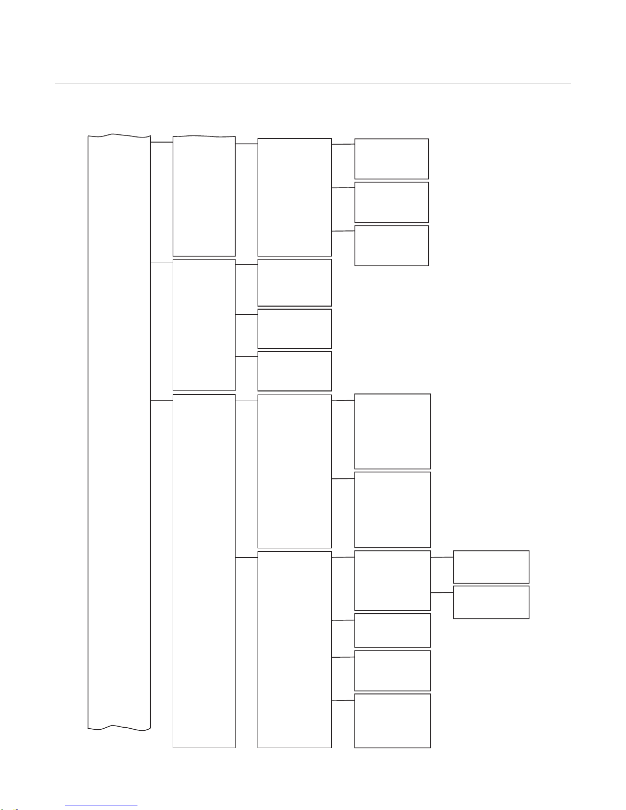
Instruction Manual
IM-106-880, Rev 2.1
April 2017
OCX 8800
6-7
Figure 6-5. HART Menu Tree (Sheet 3 of 4)
(CONTINUED FROM
SHEET 2 )
Diag/Service
(continued)
Basic Setup
Detailed Setup
(CONTINUED ON
SHEET 4)
(CONTINUED FROM
SHEET 2 )
Heater PID
Device
Information
HART Information
S/W Version Info
Cal Setup
Input/Output
O2 PID
COe PID
SB PID
Date
Descriptor
Message
Final Asmbly Num
O2 Sensor S/N
COe Sensor S/N
Tag
Poll Addr
Dev ID
Num Req Preams
Fld Dev Rev
Version
Checksum
Build Number
Build Date
Restart Cntr
O2 Cal Params
COe Cal Params
Alarm Relay
Blowback
COe Zero
O2 Prop
O2 Int
O2 Duty Cycle
O2 Set Point
O2 Temp
COe Prop
COe Int
COe Duty Cycle
COe Set Point
COe Temp
SB Prop
SB Int
SB Duty Cycle
SB Set Point
SB Temp
Solenoids
Gas Time
Purge Time
O2 Out Tracks
O2 High Gas
O2 Low Gas
O2 Cal Intrv
O2 Next Cal Time
O2 Tol Check
Cal Rec Enable
Solenoids
Gas Time
Purge Time
COe Out Tracks
COe Test Gas
COe Cal Intrv
COe Next Cal Time
COe Slope Warn
COe Tol Check
Cal Rec Enable
O2 Analog OutputAnalog Output O2 AO Range
COe Analog Output
Alarm Relay State
Trig 1 Event
Trig 2 Event
Trig 3 Event
BlBk State
BlBk Enabled
BlBk Intrvl
BlBk Period
BlBk Purge Time
Zero State
Zero Enabled
Zero Intrvl
Zero Flow
Zero Purge
Zero Tracks
Zero Update
O2 URV
O2 LRV
O2 Alarm Level
COe AO Range
COe URV
COe LRV
COe Alarm Level
39930014
Page 96

Instruction Manual
IM-106-880, Rev 2.1
April 2017
OCX 8800
6-8
Figure 6-6. HART Menu Tree (Sheet 4 of 4)
(CONTINUED FROM
SHEET 3 )
Detailed Setup
(continued)
Review
Device Params
LOI Params
Device
Information
HART Information
Cal Setup
Input/Output
Device Params
LOI Params
O2 Slope
O2 Const
O2 T90
COe Slope
COe Const
COe T90
PCNC Enable
PCDC Enable
User Intface
Luminance
Lockout Time
Revert Time
Manufacturer
Model
Date
Descriptor
Message
Final Asmbly Num
O2 Sensor S/N
COE Sensor S/N
Hardware Rev
Software Rev
Tag
Poll Addr
Dev ID
Num Req Preams
Fld Dev Rev
Universal Rev
O2 Cal Setup Solenoids
COe Cal Setup Solenoids
O2 URV
O2 LRV
COe URV
COe LRV
O2 AO Range
COe AO Range
O2 Alarm Level
COe Alarm Level
Trig 1 Event
Trig 2 Event
Trig 3 Event
BlBk Enabled
BlBk Intrvl
BlBk Period
BlBk Purge Time
Zero Enabled
Zero Intrvl
Zero Flow
Zero Purge
Zero Tracks
Zero Update
O2 Slope
O2 Const
O2 T90
COe Slope
COe Const
COe T90
PCNC Enable
PCDC Enable
Luminance
Lockout Time
Revert Time
Gas Time
Purge Time
O2 Out Tracks
O2 Low Gas
O2 High Gas
O2 Cal Intrvl
O2 Next Cal Time
O2 Tol Check
Cal Rec Enable
Gas Time
Purge Time
COe Out Tracks
COe Test Gas
COe Cal Intrvl
COe Next Cal Time
COe Slope Warn
COe Tol Check
Cal Rec Enable
39930015
Page 97

Instruction Manual
IM-106-880, Rev 2.1
April 2017
OCX 8800
6-9
Failure Priority
Maintenance Priority
Advisory Priority
Failure Active
Maintenance Active
Advisory Active
Failure Enable
Maintenance Enable
Advisory Enable
Failure Mask
Maintenance Mask
Advisory Mask
PWA Simulate
Failure Active
Maintenance Active
Advisory Active
PWA Simulate
Detailed Status
Recommended Action
Health Index
Failure Alarm
Maintenance Alarm
Advisory Alarm
Value
Subcode
Time Start
Alarm State
Unacknowledge
Failure Active
Failure Mask
Maintenance Active
Maintenance Mask
Advisory Active
Advisory Mask
Value
Subcode
Time Start
Alarm State
Unacknowledge
Block Mode: Actual
Block Mode: Target
Resource State
Fault State
Block Error
Detailed Status
Summary Status
Alarm Summary
Value
Subcode
Time Start
Alarm State
Unacknowledge
Master Reset
Self Test
DD Version Info
Transmitter Options
PlantWeb Alerts
Simulate PWA
Simulate Status
PWA Status
PWA SubStatus
Status
Methods
Manufacturer ID
Device Type
Device Revision
DD Revision
Characteristics
Tag Description
Hardware Revision
Software Revision
Private Label Distributor
Final Assembly Number
Output Board
Serial Number
ITK Version
Block Mode: Actual
Block Mode: Target
Block Mode: Permitted
Strategy
Alert Key
Sched Remote Casacade
Sched Remote Out
Grant Deny: Grant
Grant Deny: Deny
Write Priority
Confirm Time
Limit Notify
Max Notify
Fault State
Set Fault State
Clear Fault State
Alarm Summary
Acknowledge Option
RESOURCE
TRANSDUCER
AI 1
AI 2
AI 3
AI 4
PID 1
ISEL
ARTHM
ADVANCED
Memory Size
Free Time
Minimum Cycle Time
Hard Types
Nonvolatile Cycle Time
Free Space
Cycle Selection
Cycle Type
Feature Selection
Features
Download Mode
Write Lock
Write Lock Definition
Physical Device Tag
Address
Device ID
Device Revision
Identification
Process*
Alarms
Hardware
Options
Continued with
Plant Web Alerts
See Sheet 2
Detail
Network
Management
Schedule
39930009
FIELDBUS MENU TREE This section consists of a menu for the Field Communicator. This menu is
specific for the OCX 8800 Applications. Refer to the Fieldbus Parameter
Descriptions for the applicable range, units, and description for the fieldbus
menu parameters.
Figure 6-7. Fieldbus Menu Tree (Sheet 1 of 3)
Continued from
Options
*Note:
Contains information regarding
specific implementation for the
fieldbus. Refer to the fieldbus
documentation for further
information.
Page 98

Instruction Manual
IM-106-880, Rev 2.1
April 2017
OCX 8800
6-10
Block Mode: Actual
Block Mode: Target
Block Mode: Permitted
Strategy
Alert Key
Characteristics
Tag Description
O2 Primary Value
O2 Secondary Value
O2 Sensor Imp
O2 Primary Value Range:
EU at 100%
O2 Primary Value Range:
EU at 0%
O2 Secondary Value Range:
EU at 100%
O2 Secondary Value Range:
EU at 0%
O2 Sensor Type
O2 T90
O2 Cal Const
O2 Slope
O2 Constant
O2 Impedance Cal
Prev O2 Slope
Prev O2 Constant
Prev O2 Impedence
Failed O2 Slope
Failed O2 Constant
COe Primary Value
COe Secondary Value
COe Primary Value Range:
EU at 100%
COe Primary Value Range:
EU at 0%
COe Secondary Value Range:
EU at 100%
COe Secondary Value Range:
EU at 0%
COe Sensor Type
COe T90
COe Cal Cons
COe Slope
COe Constant
Prev COe Slope
Prev COe Constant
Failed COe Slope
Failed COE Constant
O2 Secondary Value
COe Secondary Value
SB Temp
Board Temp
CJC Temp
O2 Temp Max
COe Max
SB Temp Max
Board Temp Max
CJC Temp Max
Heater Control
O2 Set Point
O2 Duty Cycle
COe Set Point
COe Duty Cycle
SB Set Point
SB Duty Cycle
O2 Sensor
O2 Sensor Imp
COe Delta Resistance
COe Reference Ohms
COe RTD Current
O2 T/C
COe T/c
SB T/C
Board Temp IC
CJC Temp Signal
39930010
Figure 6-8. Fieldbus Menu Tree (Sheet 2 of 3)
Process
O2
See Sheet 1
COe
RESOURCE
TRANSDUCER
AI 1
AI 2
AI 3
AI 4
PID
ISEL
ARTHM
ADVANCED
Temperatures
Raw Inputs
Continued
with O2 Cal
Sheet 3
Page 99

Instruction Manual
IM-106-880, Rev 2.1
April 2017
OCX 8800
6-11
Cal Status
Verify Status
COe Cal Setup
COe Sensor Cal Date
COe Sensor Cal Loc
COe Sensor Cal Who
O2 Primary Value
COe Primary Value
Cal State
Cal Time Remain
Calibration Results
O2 Primary Value
CO2 Primary Value
Verify State
Verify Time Remain
Solenoids
Gas Time
Purge Time
COe Test Gas
Cal Recommended
COe Cal Interval
COe Next Cal
COe Slope Warning
COe Tolerance Check
O2 Cal
COe Cal
Alarm Relay
Blow Back
Cal Status
O2 Primary Value
COe Primary Value
Cal State
Cal Time Remain
Calibration Results
O2 Primary Value
CO2 Primary Value
Verify State
Verify Time Remain
Solenoids
Gas Time
Purge Time
Cal Recommended
O2 High Gas
O2 Low Gas
O2 Cal Interval
O2 Next Cal
O2 Tolerance Check
O2 Sensor Cal Date
O2 Sensor Cal Loc
O2 Sensor Cal Who
Blow Back
Blowback State
Blowback Enabled
Blowback Interval
Blowback Duration
Blowback Purge Time
Initate Blowback
Alarm Relay State
Alarm Relay Event1
Alarm Relay Event2
Alarm Relay Event3
COe Zero
COe Zero State
COe Zero Enable
COe Zero Interval
COe Duration
COe Zero Purge Time
COE Zero Output Track
COe Zero Update
Other
Operating Mode
Sensor Housing Type
Line Voltage
Line Frequency
Version
Build Number
Checksum
Build Date
Simulate Status
Tb Detailed Status 1
Tb Detailed Status 2
Status
Block Mode: Actual
Transducer Error
Static Revision
Block Error
Tb Detailed Status 1
Tb Detailed Status 2
Stats Attempts
Stats Failure
Methods
OCX Calibration
OCX Verify
Reset Max Temperature
(For Service Only)
39930011
Figure 6-9. Fieldbus Menu Tree (Sheet 3 of 3
continued from
Raw Inputs
Sheet 2
Continued from
Alarm Relay
Blow Back
Continued
with COe Zero
Page 100

Instruction Manual
IM-106-880, Rev 2.1
April 2017
OCX 8800
6-12
 Loading...