

Rosemount NGA 2000 TFID Hydrocarbon Analyzer Module SW 3.4 Software-1st Ed. Manuals & Guides
Instruction Manual
ETC00612
02/2001
Instruction Manual
Software Manual 3.4.x
Thermo Flame Ionization Detector
TFID Analyzer or Analyzer Module (combined with NGA 2000
Platform, MLT or CAT 200)
st
Edition 02/2001
1
www.EmersonProcess.com

TFID Software 3.4.x Instruction Manual
ETC00612
02/2001
ESSENTIAL INSTRUCTIONS
READ THIS P AGE BEFORE PROCEEDING!
Emerson Process Management (Rosemount Analytical) designs, manufactures and test s
its products to meet many national and international standards. Because these instruments
are sophisticated technical products, you MUST properly install, use, and maintain
them to ensure they continue to operate within their normal specifications. The following
instructions MUST be adhered to and integrated into your safety program when installing,
using and maintaining Emerson Process Management (Rosemount Analytical) products.
Failure to follow the proper instructions may cause any one of the following situations to
occur: Loss of life; personal injury; property damage; damage to this instrument; and warranty
invalidation.
• Read all instructions prior to installing, operating, and servicing the product.
• If you do not understand any of the instructions, contact your Emerson Process
Management (Rosemount Analytical) representative for clarification.
• Follow all warnings, cautions, and instructions marked on and supplied with the product.
• Inform and educate your personnel in the proper installation, operation, and
maintenance of the product.
• Install your equipment as specified in the Installation Instructions of the appropriate
Instruction Manual and per applicable local and national codes. Connect all products
to the proper electrical and pressure sources.
• T o ensure proper performance, use qualified personnel to install, operate, update, program,
and maintain the product.
• When replacement parts are required, ensure that qualified people use replacement parts
specified by Emerson Process Management (Rosemount Analytical). Unauthorized parts
and procedures can affect the product’s performance, place the safe operation of your
process at risk, and VOID YOUR W ARRANTY. Look-alike substitutions may result in fire,
electrical hazards, or improper operation.
• Ensure that all equipment doors are closed and protective covers are in place, except
when maintenance is being performed by qualified persons, to prevent electrical
shock and personal injury.
The information contained in this document is subject to change without notice. Misprints
reserved.
1st Edition 02/2001
© 2001 by Emerson Process Management
Emerson Process Management
GmbH & Co. OHG
Industriestrasse 1
D-63594 Hasselroth
Germany
T +49 (0) 6055 884-0
F +49 (0) 6055 884-209
Internet: www.EmersonProcess.com

Contents
1 Introduction 1 - 1
2 Menu Structure 2 - 1
3 Startup and Operation, General Notes and Main Menu 3 - 1
3.1 Starting and Initializing...................................................................................3 - 1
3.2 Display and Function......................................................................................3 - 2
3.3 "TAG" and Operating Keys ............................................................................ 3 - 2
3.4 Lines and Softkey Functionality ..................................................................... 3 - 3
3.5 Important Function Softkeys .......................................................................... 3 - 4
3.6 Entering/Changing of Variables ..................................................................... 3 - 5
3.7 Executing a Function......................................................................................3 - 6
3.8 Main Menu ..................................................................................................... 3 - 7
4 Analyzer Basic Controls (Calibration) and Setup 4 - 1
4.1 Analyzer Channel Status................................................................................4 - 3
4.1.1 Status Details
– e.g. Failures........................................................................ 4 - 5
– e.g. Acknowledge and Clear Failures.................................4 - 9
4.1.2 Current Operation Parameters (Analyzer Operation Settings)....................... 4 - 13
4.2 Single Component Display - Change of Channel........................................... 4 - 15
4.3 Multi Component Display - Change of Channel............................................. 4 - 17
4.4 Calibration Procedure Status.........................................................................4 - 19
4.5 Zero Calibration..............................................................................................4 - 21
4.6 Span Calibration/ Basic Parameters..............................................................4 - 25
4.7 Active Zero Gas, Span Gas, Sample Gas or Test Gas - Close all Valves ..... 4 - 29
4.8 Flow measurement.........................................................................................4 - 31
ETC00612(1) [NGA-e (TFID SW 3.4.X)] 06/01
NGA 2000 I

5 Analyzer and I/O, Expert Controls & Setup 5 - 1
5.1 Analyzer Module Setup (or Controls)..............................................................5 - 3
5.1.1 Calibration Parameters...................................................................................5 - 5
– Span gases.........................................................................................5 - 6
– Tolerances ..........................................................................................5 - 8
– Calibration procedure setup................................................................5 - 10
– Time controlled calibration..................................................................5 - 13
– Calibration...........................................................................................5 - 15
– Advanced calibration methods............................................................5 - 18
– Zero Gases.........................................................................................5 - 20
5.1.2 Alarm Parameters...........................................................................................5 - 21
5.1.3 Range parameters..........................................................................................5 - 25
– Begin and end of ranges.....................................................................5 - 27
– Response times (t90) ...........................................................................5 - 28
– Autoranging control.............................................................................5 - 29
5.1.4 Cross Interference Compensation..................................................................5 - 31
5.1.5 Linearization...................................................................................................5 - 33
5.1.6 Programmable Logic Control (PLC)................................................................ 5 - 37
5.1.7 Programmable Calculator...............................................................................5 - 45
5.1.8 Measurement Display Configuration...............................................................5 - 49
5.1.9 Acknowledgement of Status Reports .............................................................5 - 53
5.1.10 Concentration Measurement Parameters.......................................................5 - 55
5.1.11 Concentration Peak Measurement.................................................................5 - 57
5.1.12 Differential Measurement ...............................................................................5 - 59
5.1.13 Gasflow Setup................................................................................................5 - 61
5.1.14 Pressure Compensation.................................................................................5 - 62
5.1.15 Flow Measurement.........................................................................................5 - 64
5.1.16 Temperature Measurement............................................................................5 - 65
5.1.17 Load/Save Analyzer Module Configuration ....................................................5 - 66
5.1.18 Inputs and Outputs (Local SIO/DIO)...............................................................5 - 69
– Local SIO .............................................................................5 - 70
– Local DIO .............................................................................5 - 76
– Signal codes .............................................................................5 - 77
5.1.19 Delay and Average.........................................................................................5 - 81
5.1.20 Special Functions...........................................................................................5 - 83
5.1.21 AK-Protocol Communication ..........................................................................5 - 84
II NGA 2000
ETC00612(1) [NGA-e (TFID SW 3.4.X)] 06/01

5.2 I/O Module Controls (System or CM SIO/DIO).............................................5 - 85
5.2.1 SIO Module..................................................................................................5 - 86
– Analog output setup.................................................................5 - 87
– Serial interface setup ...............................................................5 - 91
– Configuration of Relay Outputs................................................5 - 92
5.2.2 DIO Module(s).............................................................................................. 5 - 95
– Configuration of the 8 DIO module inputs................................ 5 - 96
– Configuration of the 24 DIO module outputs............................5 - 98
5.3 I/O Module Setup (Network I/O Modules)....................................................5 - 101
6 System Configuration and Diagnostics 6 - 1
6.1 Diagnostic Menus...........................................................................................6 - 3
6.1.1 Control Module Diagnostics................................................................. 6 - 4
6.1.2 Analyzer Module Diagnostics..............................................................6 - 5
6.2 Load/Save Module Configuration................................................................... 6 - 6
6.3 Date and Time ...............................................................................................6 - 7
6.4 Security Codes............................................................................................... 6 - 8
6.5 Network Module Binding................................................................................6 - 10
6.6 System Reset................................................................................................. 6 - 12
7 Display Controls 7 - 1
Supplement:
System Calibration
Tables:
Response factors
Conversion factors ppm ↔↔↔↔ mg/Nm³
Index
ETC00612(1) [NGA-e (TFID SW 3.4.X)] 06/01
NGA 2000 III
1 Introduction
This software manual describes step by step how to operate successfully with the
NGA 2000 Series 19" TFID (Thermo-FID) analyzer modules and analyzers.
Chapter 2 shows the TFID software menu structure. Chapter 3 describes the analyzers
display and keyboard as well as the main menu and submenus. Chapter 4 describes the
basic controls incl. calibration with detaile d illustra tions. So you ca n easily comp are the
actual analyzer (module) display with the illustrations of this manual.
Chapter 5 describes the expert configurations of the analyzer module and of the I
utput Modules (I/O modules). Chapter 6 describes the system configuration and
O
nput/
diagnostics. The layout of both chapters is not as detailed as of chapter four. By default,
the way through the menus is described giving the menu lines you have to enter
sequentially to reach a specific menu within the TFID software . At the end of this
description you will find an illustration of the final submenu screen followed by set up
instructions and explanations of functions and variables of each expert or system
configuration menu. Chapter 7 will give you some information about the display controls.
Not all sections of Chapter 5 (expert configurations) are important for each operator.
Which section is of interest depends on the NGA 2000 configuration with reference to the
following components:
♦
Control Module CM
♦
Analyzer Module AM
♦
Input/Output Modules I/O's (SIO = Standard I/O, DIO = Digital I/O)
♦
Network I/O Modules Analog Output with 3 Alarms I/O, Auto Calibration I/O,
System Auto Calibration I/O
You can distinguish the following system units and SIO/DIO configurations:
System Unit SIO/DIO-Configuration
Section
Page
TFID analyzer module (AM):
•
without front panel,
i.e. without control unit
•
can be combined with a platform, a
MLT analyzer, a TFID analyzer or a
customer developed control unit
Platform (CM S oftware):
•
Control unit with front panel
•
Without measurement channels
TFID analyzer (CM plus TFID AM
software = TCA software):
•
Analyzer with front panel
•
CM and AM software in the same
analyzer, i.e. all functions of the
control unit and of the AM are
combined in one controller board
⇒
1 local SIO and 1 local DIO (or 2
local DIO’s) can be installed in the
TFID/MLT analyzer module
⇒
SIO and DIO can be configured
for the MLT AM channels or the
TFID analyzer module only
⇒
1 SIO and up to 4 DIO's can be
installed in the platform (CM I/O)
⇒
SIO and DIO can be configured
for all MLT channels % AM’s
combined with the platform
⇒
1 SIO and 1 DIO (or 2 DIO’s) can
be installed in the TFID/MLT
analyzer (CM I/O)
⇒
SIO and DIO can be configured
for all MLT channels and AM’s
combined with the TFID/MLT
analyzer
∗ 5.1.18
p. 5-69
∗ 5.2
p. 5-85
∗ 5.2
p. 5-85
ETC00612(1) [NGA-e (TFID SW 3.4.X)] 02/01
NGA 2000
1 - 1
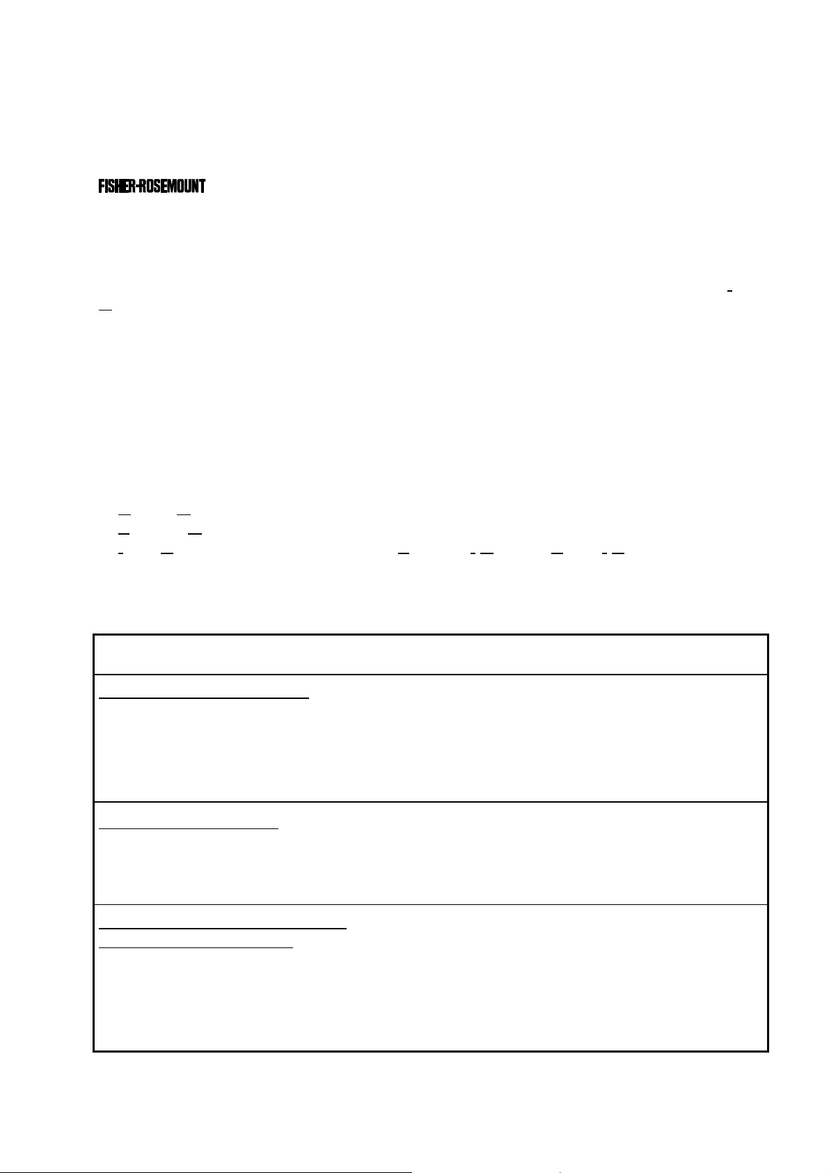
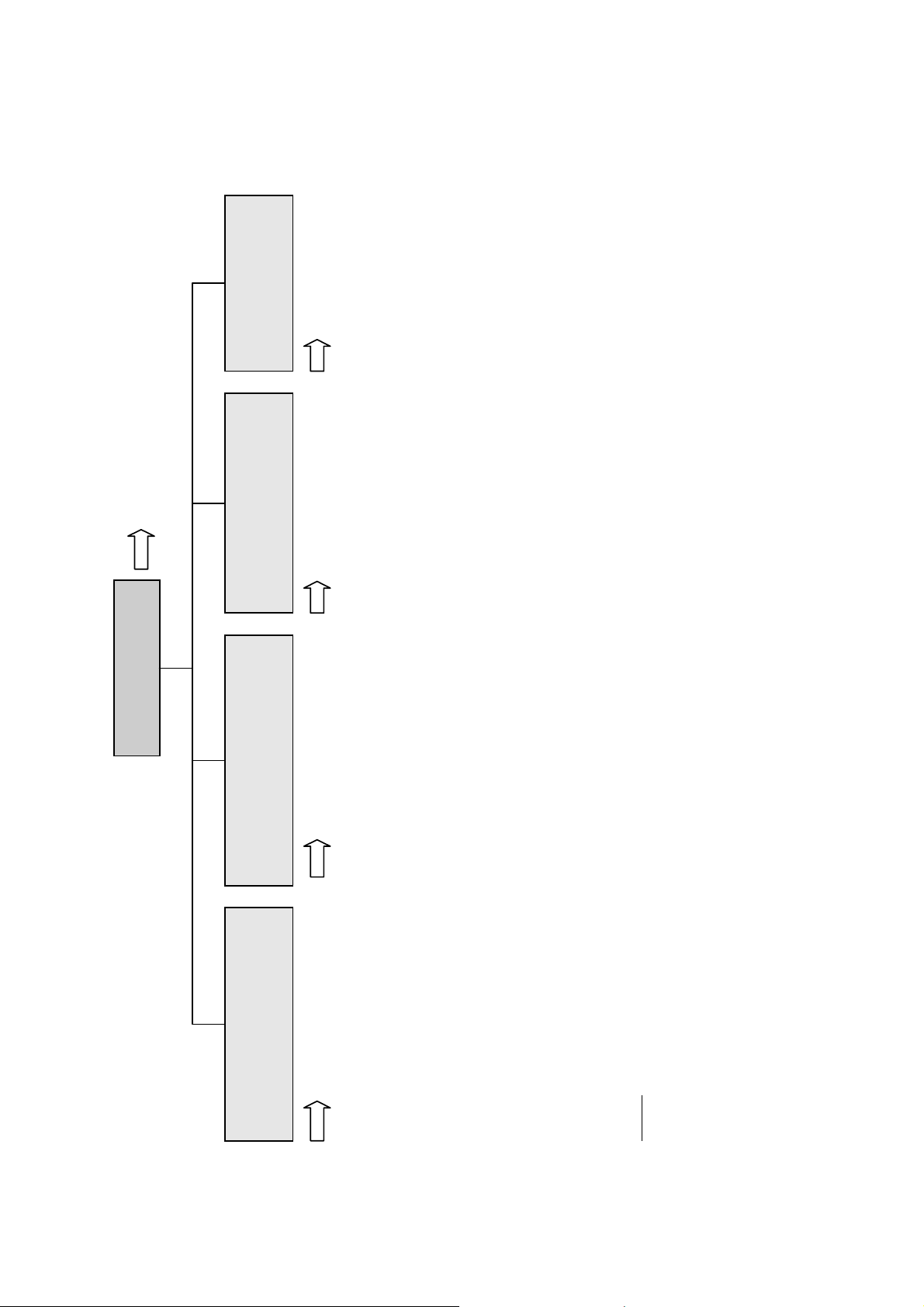
The following illustrations explain the relationship between the hardware configuration and
A
the software setup of the modules:
NGA 2000 System containing a Platform
(see 5.1.18)
(see 5.1.18)
Local
I/O's
SIO
nalyzer
Modules (AM's)
Control
Module (CM)
System I/O
TFID
DIO
SIO
MLT
DIO
(additional
manuals)
(additional
manuals)
(additional
manuals)
CLD
Platform
PMD
FID
NG A 2000 Sy stem containing an TFID Analyzer
Modules
1 SIO
4 DIO's
max.
Network I/O
(see 5.2.1)
(see 5.2.2)
(see 5.1.18)
(see 5.1.18)
Local
I/O's
SI O
DIO
SI O
DIO
(additional
manuals)
(additional
manuals)
(additional
manuals)
Analyzer
Modules (AM's)
TFID
MLT
CLD
PMD
FID
Control
Module (CM)
System I/O
Modules
1 SIO
(see 5.2.1)
1 DIO
(see 5.2.2)
TFID Analyzer
1 - 2
NGA 2000
ETC00612(1) [NGA-e (TFID SW 3.4.X)] 02/01
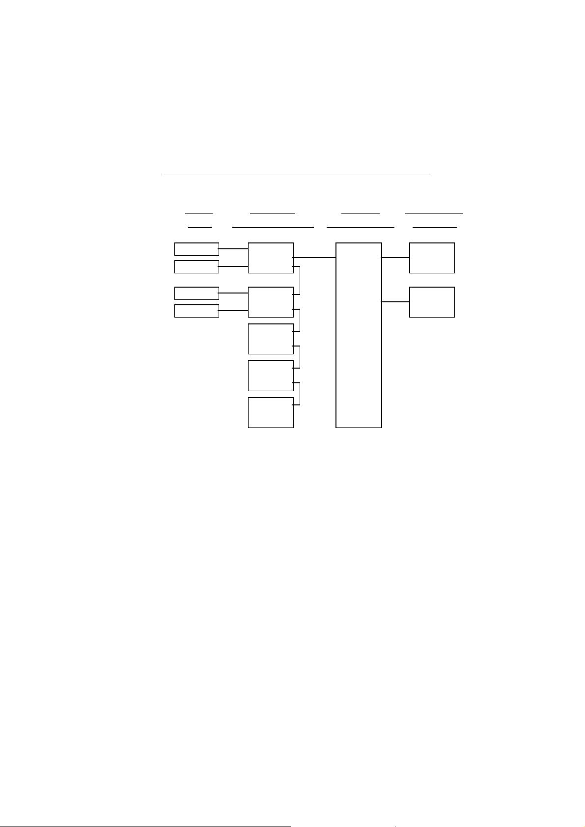
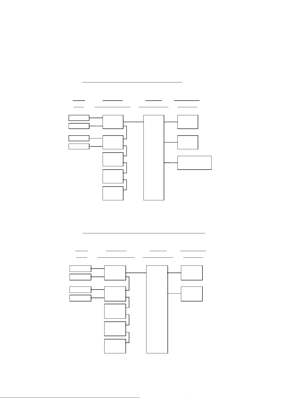
1 Introduction
NGA 20 0 0 Sys te m co nt aining an ML T Ana ly zer
Local
I/O's
(see 5.1.18)
(see 5.1.18)
SIO
DIO
SIO
DIO
(additi onal
manuals)
(additi onal
manuals)
(additi onal
manuals)
Note:
This software manual describes the software of all TFID analyzers and TFID analyzer
modules combined with a platform, an FTID analyzer or an MLT analyzer.
It will not describe the software of TFID analyzer modules running at a customer control
unit.
The software of MLT analyzers / MLT analyzer modules is nearly identically to the TFID
software. An separate software manual is available containing the MLT specific functions.
Analyzer
Mod u le s (AM's)
MLT
TFID
CLD
PMD
FID
Control
Mod u le (CM)
MLT Analyzer
System I/O
Modules
1 SIO
1 DIO
( see 5. 2 .1)
( see 5. 2 .2)
ETC00612(1) [NGA-e (TFID SW 3.4.X)] 02/01
NGA 2000
1 - 3

1 - 4
NGA 2000
ETC00612(1) [NGA-e (TFID SW 3.4.X)] 02/01
2 Menu Structure
Section 3.8
System configuration
Main Menu
Analyzer and I/O, expert
Display controls...
- Brightness:
- Contrast:
(CM)
to "Measure" after
- Switch automatically
...
and diagnostics...
(AM, CM, network I/O's)
- System calibration...
- Diagnostic menus...
local SIO/DIO)
incl.
(CM/MCA)
- Load/save configuration
controls & setup...
(AM
- Analyzer module controls...
(System I/O's: SIO, DIO)
module controls...
- System & network I/O
(CM)
(Lock any level)
- Security codes (PIN)...
- Date and time...
like
controls)
MLT/TFID
for
analyzer module
(AM:
- Analyzer module setup...
(CM)
(CM)
(AM, CM, I/O's: SIO, DIO etc.)
- Network module managment...
- System reset...
- System tag:
(Network I/O's)
module setup...
- System & network I/O
(calibration) & setup...
Analyzer basic controls
ETC00612(1) [NGA-e (TFID SW 3.4.X)] 02/01
Section 4 Section 5 Section 6 Section 7
- Flow zero gas!
- Calibration procedure state...
- Start zero calibration procedure!
- Start span calibration procedure!
- Check calibration deviation:
- Range number:
- Span gas:
- Range upper limit:
NGA 2000
- Flow span gas!
- Valves => F5:
- Flow sample gas!
- Flow test gas!
- Close all valves!
Notes:
the function, lines ending with ":" display module parameters - some can be changed.
* All setups in the menu "Analyzer basic controls (calibration) & setup" are valid for the analyzer or analyzer module (AM).
* Menu lines ending with three points (...) are followed by submenus with further functions and setups, lines ending with "!" allow to start
you can find which functionality will be setup:
AM (A nalyzer Module), CM (C ontrol Module), local, system or network I/O (Input/Output Module).
* At each menu point of the "Analyzer and I/O, expert controls & setup" and "System configuration and diagnostics"
2 - 1

2 - 2
NGA 2000
ETC00612(1) [NGA-e (TFID SW 3.4.X)] 02/01
3
A
Startup and Operation, General Notes and Main Menu
3.1 Starting and Initializing (Refer to the operation manual, too !)
After switching on the TFID analyzer / analyzer module ( as part of a NGA network), the
initialization procedure will be performed. . A self test is started showing a sequence of
several screens with information about the initialization status, software revision notes and
the
tag:
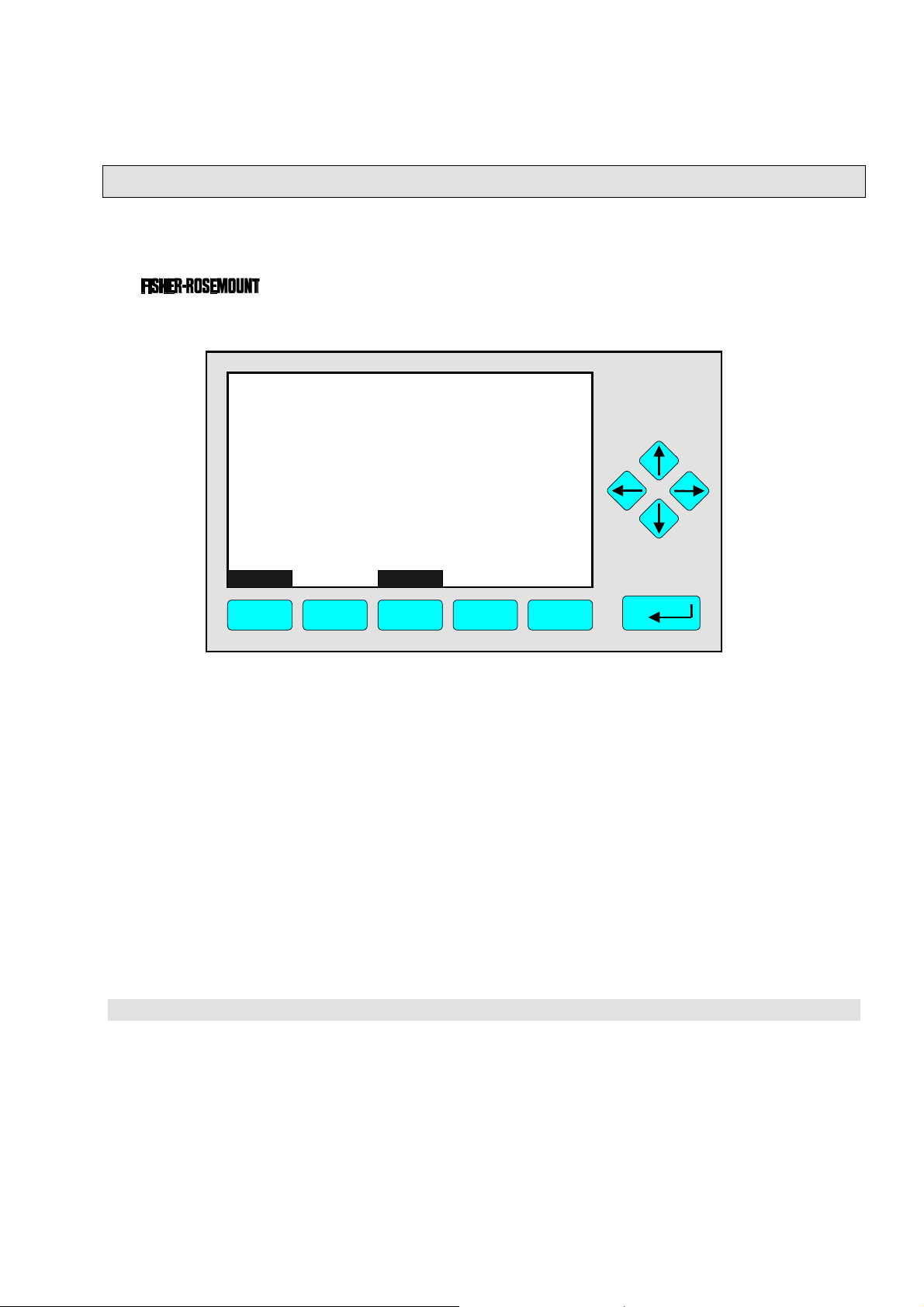
(C) 2000 FISHER-ROSEMOUNT Analytical
NGA-2000 Control-Module Rev. 3.4 /P010
LCDReset
F1 F2 F3 F4 F5
Language:P010/01/00
Initializing Network
Initializing network interface
bort
The network is initialized while the screen shows the messages “Initializing network
interface” , “ Searching for nodes” and “Calculating binds”.
If you press the F1-key during the initializing, you will reset the LCD brightness and
contrast to factory settings (see also section 7). Pressing the F3-key will abort the
network initializing. There will be no connection to any analyzer module. Only the control
module menus (platform or TFID analyzer) will be available.
At the end of the initializing procedure you can see the single component display of
channel one (see illustration on next page). It is the starting point to all the other channel
displays, menus and submenus.
The instructions of the basic controls (chapter four) are all beginning at the single component display. Since this screen is customer configurable the actual analyzer display
might differ from the one shown in this manual (see section 5.1.8 pg. 5-49 and section 7).
ETC00612(1) [NGA-e (TFID Software 3.4.X)] 06/01
NGA 2000
3 - 1

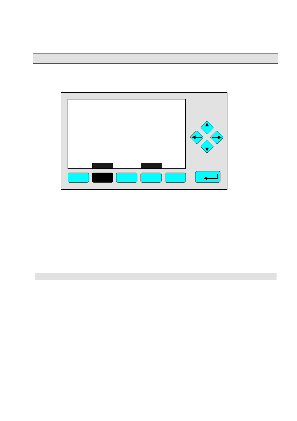
3.2 Display and Function
The LCD screen shows all analyzer measurement values and all customer instructions.
You can operate with five function keys, four arrow keys (cursors) and the enter key. The
function of each key depends on:
♦
the type of analyzer/analyzer module used
♦
the optional auxiliary modules (e.g. I/O boards) used
♦
the individual menu displayed
In case of power failure all customer specific module parameters are saved in a battery-
powered buffer.
3.3 "TAG" and Operating Keys
At the top left of each menu page you will find the tag of the current channel.
Typical tags:
♦ TFID/R1: T
♦
MLT/CH1/R1: MLT Analyzer or Analyzer Module / CHannel 1 / Range 1
By default screen dumps in this manual will show "TAG". Specific TFID menu pages will use
"TFID" instead to show this property.
hermo FID Analyzer or Analyzer Module / Range 1
TAG
37.50 ppm CH4
0.00 50.00
Failures: No
Maintenance-Requests: No
Temperature: 20.0 C
Operation: Ready
Display Status... Main... Channel
F1 F2 F3 F4 F5
Range: 1
0.0 100.0
BasicCal
Function Keys:
♦
Keys without defined function
♦
The current function depends on
the menu selected
♦
The softkey legend is shown on
the display right above the key
Cursor keys:
↑↑↑↑ -key / ↓↓↓↓ -key:
♦
Line up / line down
within the same menu
♦
Alteration of numbers,
variables or digits
←←←← -key / →→→→ -key:
♦
Moving back/forth
between the pages of
a menu
♦
Selection of digits
♦
Start a selected
function
Enter Key:
♦
To confirm a previously entered value
(variable)
♦
To start a selected function
(alternative
♦
To enter a menu (via menu line)
: →→→→ -key)
3 - 2
NGA 2000
ETC00612(1) [NGA-e (TFID Software 3.4.X)] 06/01
3
p
w
Startup and Operation, General Notes and Main Menu
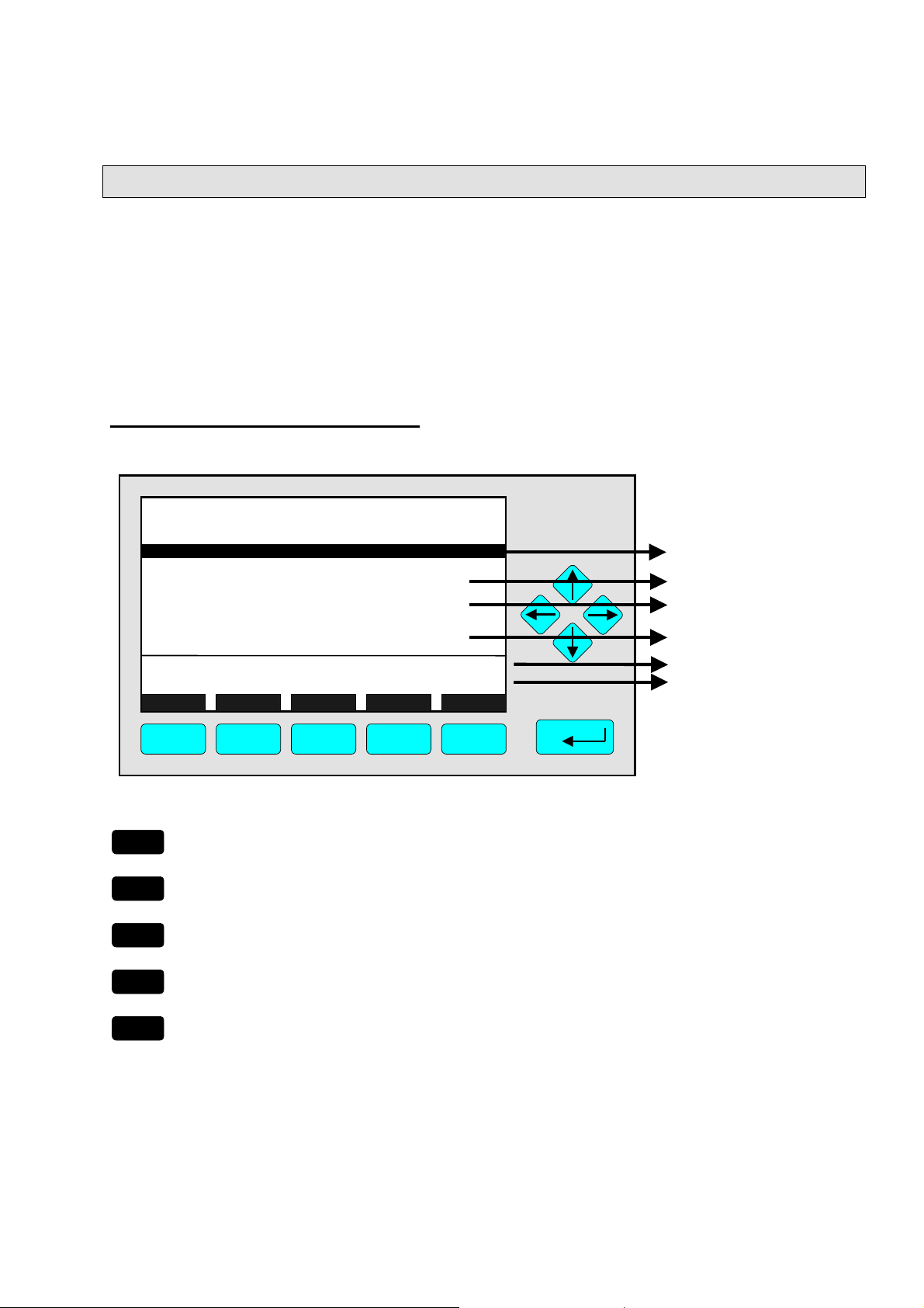
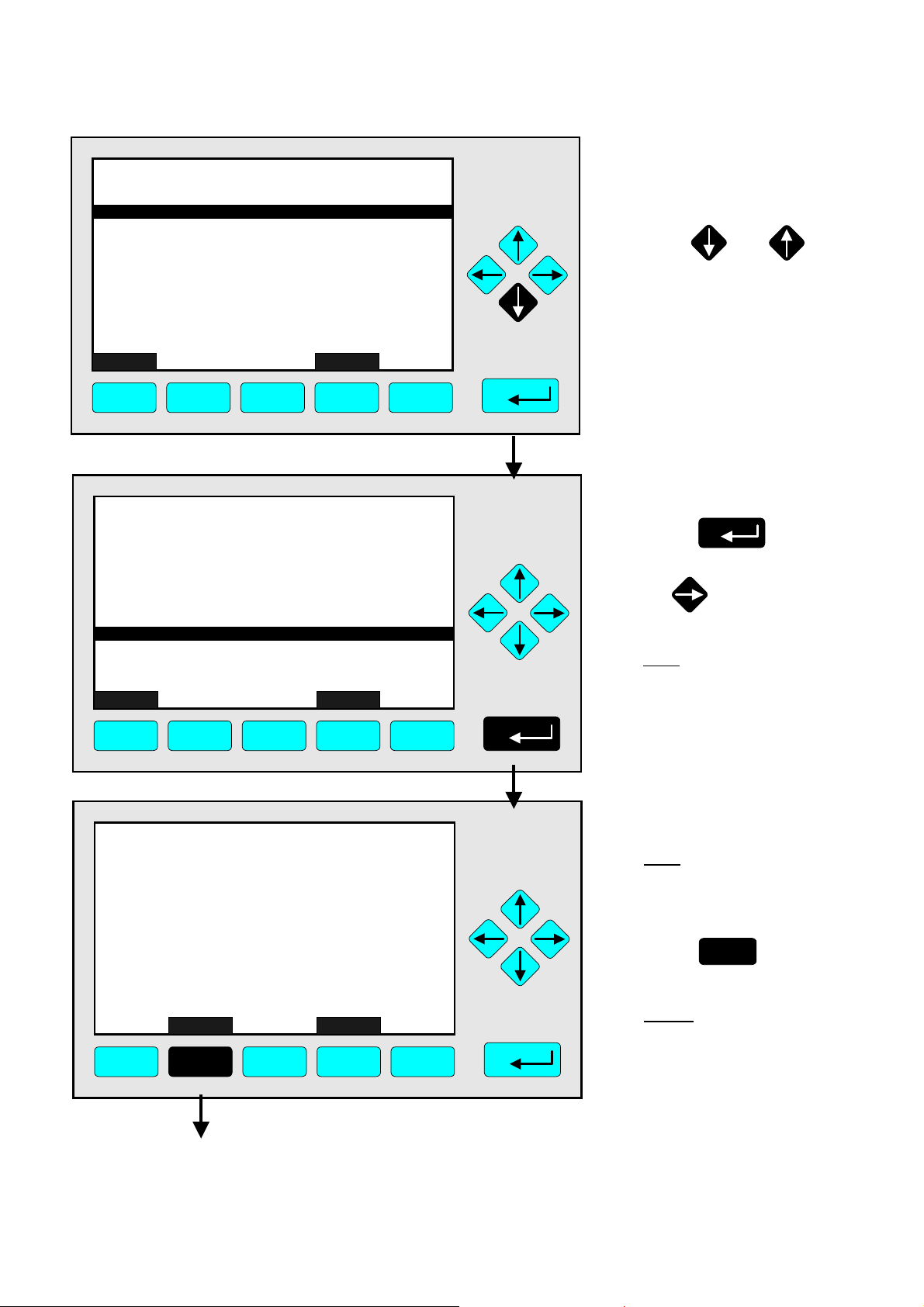
3.4 Lines and Softkey Functionality
Lines can be selected by using the ↓↓↓↓ -key or the ↑↑↑↑ -key. The selected line is displayed
white on black (highlighted). There are four different types of lines in the menus:
Menu line... / Menu Softkey...
♦
Line/Softkey description ending with three dots.
♦
You will enter a submenu/next menu by pressing the softkey resp. by pressing the
↵↵↵↵
-key or the →→→→ -key while the menu line is highlighted.
Function line / Function Softkey !
♦
Line/Softkey description ending with an exclamation-mark.
♦
You will start a function (e.g. calibration) by pressing the softkey resp. by pressing the
↵↵↵↵
-key or the →→→→ -key while function line is highlighted.
Line of variables:
♦
Line ending with a colon.
♦
View module parameters (variables).
♦
Some parameters can be changed (e.g. begin of range). Other parameters showing a
status (e.g. temperature) are for information only and cannot be changed. They are
displayed below a separation line within the menu.
Text line
♦
Line without any punctuation marks.
♦
Giving additional information only (such as headlines a.s.o.).
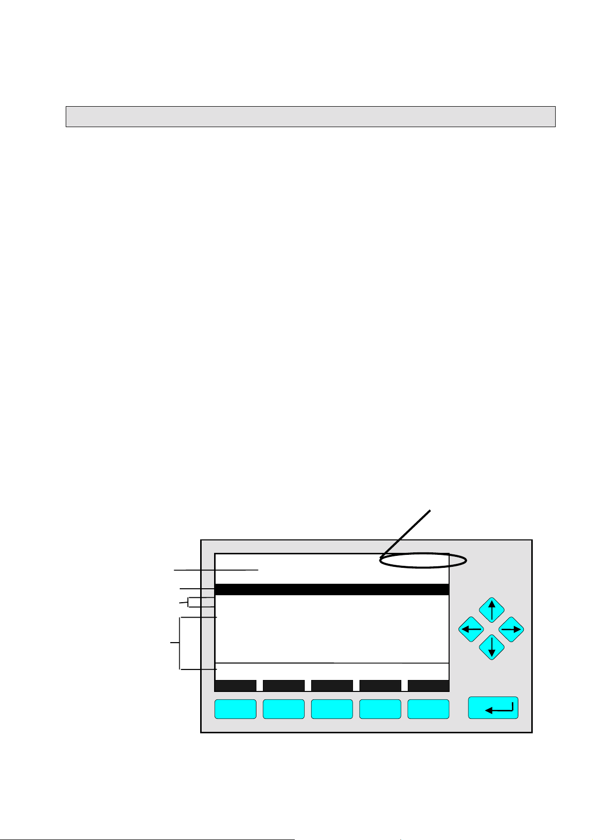
The following illustrations explain the function of lines and softkeys as described above:
Current channel measurement signal (see TAG).
It is always shown on the single component display.
Menu Headline
Menu Line
Function Lines
Lines of Variables
(The last one can not
be changed – belo
the separation line)
TAG
-- Basic Controls and Setup --
Calibration procedure status...
Start zero calibration procedure!
Start s
Check calibration deviation:
Range number:
Span gas: 100 ppm
Range upper limit: 100 ppm
Operation status: Ready
an calibration procedure!
Measure Status... Channel Back...
37.50 ppm
Enabled
1
Valves...
F1 F2 F3 F4 F5
ETC00612(1) [NGA-e (TFID Software 3.4.X)] 06/01
NGA 2000
3 - 3
TAG
Text Line
-- Calibr ation Pr oc edure State --
Proc edure state:
Maximum rema in ing procedure time :
Valve position:
Concent ration in span gas units:
Last zero calibration:
Last span calibrati on:
Last zero calibration was:
Last spa n cal ibra t ion was:
Succ essful zero+span ca libr ated ranges:
Measure Cancel !
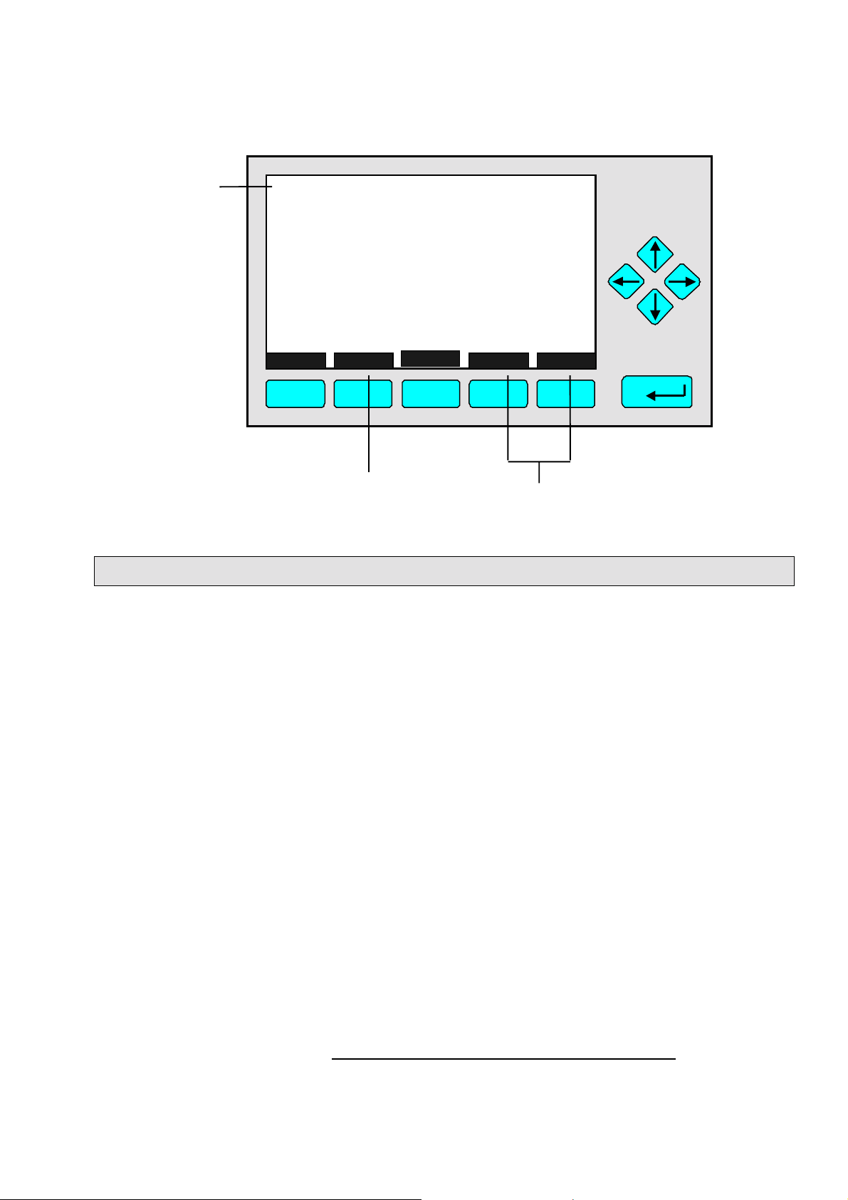
F1 F2 F3 F4 F5
Function Softkey
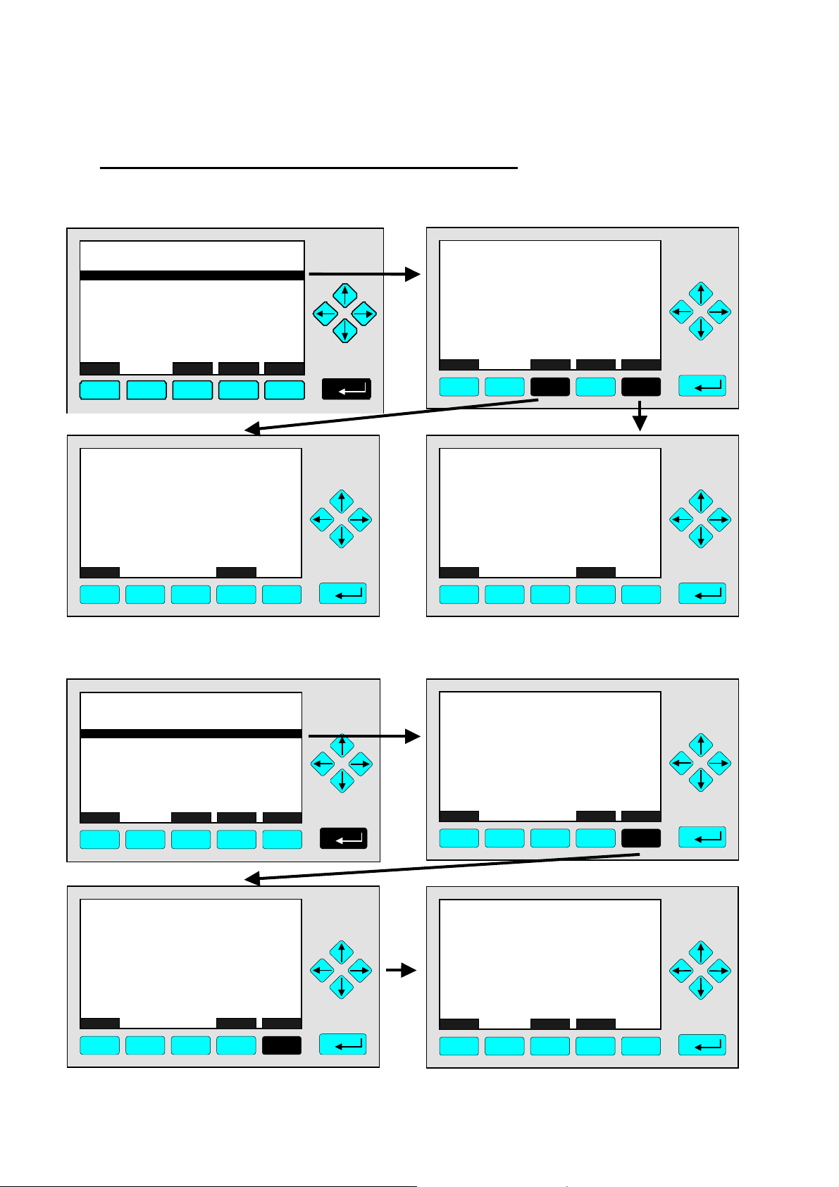
3.5 Important Function Softkeys
Channel
37.50 ppm
Ready
Samplegas
37.50 ppm
Success
Success
1+2+3+4
More...
Fr i 05-29-1998 13:32:0 6
Fr i 05-29-1998 13:37:2 3
Back...
Menu Softkeys
0 s
Display
♦
Switch from the single component display to the multi component display.
♦
F1 in the single component display.
Measure
♦
Switch from any menu or submenu to the single component display of the selected
channel.
♦
F1 in any screen except the single component display.
Status (see section 4.1 page 4-3!)
♦
Switch to the menu "Analyzer Channel Status":
Shows the most important parameters and information about the status of the current
channel or module.
♦
If available: F2.
Main (see section 3.8 page 3-7!)
♦
Switch from the single component display to the main menu.
♦
F3 in the single component display.
Channel
♦
Scroll through the channels in the current menu. In the main menu and the single
component display you may scroll through all channels of the connected analyzer /
analyzer modules. In submenus this key is without function although it is displayed (only
activated in MLT software). TFID is a single channel analyzer or AM only!
♦
If available: F3 (F4 in the single component display).
3 - 4
NGA 2000
ETC00612(1) [NGA-e (TFID Software 3.4.X)] 06/01

3
Startup and Operation, General Notes and Main Menu
Lock
♦
Lock all three operation levels at the main menu if a security code is activated in the
system configuration and diagnostic menu (see section 6.4 pg. 6-8).
♦
F4 in the main menu.
BasicCal (see section 4.4 pg. 4-19 and 5.1.1 pg. 5-15!)
♦
Switch from the single component display to the menu "Analyzer module calibration".
♦
F5 in the single component display.
MFG Data (see section 3.8 pg. 3-7/8!)
♦
Switch from the main menu to the menu "Module Manufacturing Data":
Additional submenus are available with information about the control module and
analyzer module data, such as manufacturer address , modules serial numbers or
software and hardware revisions.
♦
F5 in the main menu.
Back
♦
Return to the previous menu page (alternative: ←←←← -key)
♦
reset a changed but not confirmed parameter to the previous value.
♦
If available: F4 for returning back, F2 for reset.
More
♦
Entering the next page of the current menu.
♦
If available: F5.
3.6 Entering/Changing Variables
↵↵↵↵
-key
♦
If you have already selected a line of variables (highlighted) and press the
↵↵↵↵
-key, the
parameter will be selected and may be edited.
↵↵↵↵
If you press the
-key again, the new value will be confirmed.
↑↑↑↑ -key / ↓↓↓↓ -key
♦
Function depends on the variable selected: - Changing the parameter values
- Scrolling among variables selecte d
- Changing single digits or characters
- Increasing or decreasing numbers.
←←←← -key / →→→→ -key
♦
Selects single digits within a number.
♦
The number of digits or characters of some variables may be changed.
ETC00612(1) [NGA-e (TFID Software 3.4.X)] 06/01
NGA 2000
3 - 5
3.7 Executing a Function
If you press the
↵↵↵↵
-key or the →→→→ - key while a functio n line is highligh ted the software will
ask for a confirmation:
TAG
-- Confirmation Required --
Do you really want to do this ??
Press "Yes" or "Back..."
Yes Back...
F1 F2 F3 F4 F5
37.50 ppm
♦
If you press the F2 -key the function will start imm e diately.
♦
Pressing the F4 -key will return to the previous menu page.
Note:
Confirmation of function line entries may be disabled:
♦
Select “Measurement Display Configuration” from the Analyzer and I/O, expert controls
& setup menu (see section 5.1.8, page 5-49).
♦
Change “Display confirmation menus” to “No”.
Now the selected function will start immediately after entering. No confirmation is
required.
3 - 6
NGA 2000
ETC00612(1) [NGA-e (TFID Software 3.4.X)] 06/01
3
Startup and Operation, General Notes and Main Menu
3.8 Main Menu
If you press the F3-key (Main...) or the →→→→-key in any single component display, you will
switch to the "Main Menu". From there you can switch to all operating levels of your
TFID/MLT analyzer / analyzer module to set up and control the parameters of
measurement, calibration and data transfer!
Via the F5-key (MFG Data) you may enter several submenus where you will find a lot of
important data about the control module (TFID/MLT analyzer / platform) and the analyzer
module, such as service address or serial number!
Ramifications from the Main Menu:
TAG
-- Main Menu --
Analyzer basic controls (calibration) & setup...
Analyzer and I/O, expert controls & setup...
System configuration and diagnostics...
Display controls...
Time & Date: 14:01:45 25 May 1999
System tag: Fisher-Rosemount
Measure Status... Channel Lock... MFG Data
F1 F2 F3 F4 F5
F1
F2
F3
Enter the current channel’s single component
display
Enter the current channel’s "Analyzer Channel
Status" menu.
Scroll through all channels of connected
analyzers / analyzer modules
95.00 ppm
☞
☞
☞
See chapter 4 !
See chapter 5 !
See chapter 6 !
See chapter 7 !
Setup: see 6.3 pg. 6-7
Factory setting
Section 3.1, pg. 3-1/2 !
Section 4.1, pg. 4-3 !
See channel tag !
F4
F5
Lock any operating level by security code
Enter the menu "Manufacturing Data"
ETC00612(1) [NGA-e (TFID Software 3.4.X)] 06/01
NGA 2000
☞
☞
Section 6.4, pg. 6-8 !
See next pages !
3 - 7
Ramifications from the menu "Manufacturing Data":
1. Control module data:
TAG
-- Manufacturing Da ta --
Control modul e manufac turing data...
Analyzer module manufacturing data.. .
Meas u re
F1
F2
<<<
F3
F4
Back...
95.00 ppm
TAG
(C) Copyright Fisher-Rosemount Analytical Inc., 2001
Manufactured by:
Rosemount Analytical Inc.
4125 East La Palma Avenue
Anaheim, CA 92807-1802 /USA
Tel: (714) 986-7600
FAX: (714) 577-8739
Measure Back...
F1 F2 F3 F4 F5
95.00 ppm
2. Analyzer module data:
>>>
F5
TAG
(C) Copyright Fisher-Rosemount GmbH & Co, 2001
Manufactured by:
Fisher-Rosemount GmbH & Co
Industriestrasse 1
D-63594 Hasselroth / Germany
Tel. (+49) 6055 884-0
FAX. (+49) 6055 884-209
Measure Or... Back... More...
F1 F2 F4 F5
F3
95.00 ppm
TAG
-- Control Module Version Information --
Serial number: CM 4711
Manufacturing date: 14.02.2001
Hardware revision: ACU02 R: 3.2.4, Final D:Jan 1
Software revision: 3.4/P010
Revision date: Nov 2 2000
Revision time: 16:09:49
Phrase dictionary version:
Language: English
Measure Back...
F1 F2 F3 F4 F5
95.00 ppm
P010/01/00
TAG
Control module data...
Analyzer module data...
Measure
F1 F2 F3 F4 F5
-- Module Manufacturing Data --
<<<
Back...
95.00 ppm
>>>
TAG
-- Analyzer Module Version Information --
Serial number: AM 4712
Manufacturing date: 14.02.2001
Hardware revision: ACU02 R: 3.2.4, Final D:Jan 1
Software revision: 3.4.1 / P010/Ch1
Revision date: Nov 2 2000
Revision time: 16:25:28
Measure Back...
F1 F2 F3 F4 F5
95.00 ppm
More...
TAG
(C) Copyright Fisher-Rosemount GmbH & Co, 2001
Manufactured by:
Fisher-Rosemount GmbH & Co
Industriestrasse 1
D-63594 Hasselroth / Germany
Tel. (+49) 6055 884-0
FAX. (+49) 6055 884-209
Measure Back... More...
F1 F2 F3 F4 F5
TAG
Measurement system: PSV-System
RAM-memory: 763296 Bytes
Local SIO module installed: Enabled
Serial interface adapter: RS-232
Heater installed: No
Local DIO module installed: 2
Sensor system revision:
Sensor system serial number:
Measure Back...
F1 F2 F3 F4 F5
-- Hardware Configuration --
Channel
95.00 ppm
95.00 ppm
04011999
311976
3 - 8
NGA 2000
ETC00612(1) [NGA-e (TFID Software 3.4.X)] 06/01
4 Analyzer Basic Controls (
Calibration) & Setup
Chapter 4 "Analyzer basic controls (calibration) & setup" describes the most important
measurement and calibration functions of your TFID/MLT analyzer / analyzer module.
All steps are figured with detailed illustrations and operation instructio ns. In the left column
you can see display and keyboard of the NGA front panel. The keys you have to press are
illustrated in black. In the right column you can read the instructions and notes. All
instructions will begin with any single component display and will end with the corresponding single component display after the setups are done. So you can easily compare the
actual display of the analyzer / analyzer module with the illustrations of this manual.
Example:
You want to change from the single component display of the TFID (propane) to the single
component display of the MLT channel 2 (CO).
• Picture one shows the starting situation: single component display of propane.
• Picture two shows the result you get if you press the F4 -key (Channel):
single component display of CO.
Left column: Right column:
Display and keyboard Instructions and notes
TFID-R1
37.50 ppm Propane
0.00 50.00
Failures: No
Maintenance- No
Temperature: 20.0 C
Operation: Ready
Display Status... Main... Channel BasisCal
F1 F2 F3 F4 F5
MLT25/CH2/R2
95.00 ppm CO
0 250Range: 2
Temperature: 25.0 C
MaintenanceAny_Alarms: No
Operation: Ready
Display Status... Main... Channel BasisCal
F1 F2 F3 F4 F5
Range: 1
0.0 100.0
0.0 100.0
No
⇒ Switch to the single
component display
of another channel
F4
Press
Notice the tag in the
display's upper left corner:
It changed fro m TFID to
MLT2 indicating a different
analyzer / analyzer module.
⇒ Next instruction
or step may be
entered.
ETC00612(1) [NGA-e (TFID SW 3.4.X)] 02/01
NGA 2000
4 - 1

4 - 2
NGA 2000
ETC00612(1) [NGA-e (TFID SW 3.4.X)] 02/01
TAG
37.50 ppm CH4
0.00 50.00
Failures: No
Maintenance-Requests: No
Temperat ure: 20.0 C
Operation: Ready
Display Status... Main... Channel BasicCal
F1 F2 F3 F4 F5
Range: 1
0.0 100.0
4.1 Analyzer Channel Status
⇒ Open the menu
"Analyzer Channel
Status"
F2
Press
The menu "Analyzer
Channel Status” displays
status information about
the current channel.
Use the menu lines
"Status details..." and
"Current operation
parameters..." to enter
submenus.
(see 4.1.1 pg. 4-5...11 and
4.1.2 pg. 4-13/14)
TAG
-- Analyzer Channel Status --
Status details...
Analyzer operation settings...
General status: Normal
Hours of operation: 164
Operation status: Ready
Events: No
Alarms: No
Failures: No
Maintenance requests: No
Function control/Service: No
Measure Channel Back...
RawMeas More...
37.50 ppm
F1 F2 F3 F4 F5
TAG
37.50 ppm CH4
0.00 50.00
Failures: No
Maintenance-Requests: No
Temperat ure: 20.0 C
Operation: Ready
Range: 1
0.0 100.0
⇒ Return to the single
component display
F1
Press
Note:
The F2 -key enters the
•
submenu “Primary raw
measurements” and
from there in a second
step using F5 to
”Secondary raw
measurements”.
Via the F5 -key you can
•
switch to submenu "TFID
Pressure & Temperature
Measurements".
⇒ Back in the single
component display
Display Status... Main... Channel BasicCal
F1 F2 F3 F4 F5
ETC00612(1) [NGA-e (TFID SW 3.4.X)] 02/01
NGA 2000
4 - 3

4 - 4
NGA 2000
ETC00612(1) [NGA-e (TFID SW 3.4.X)] 02/01
4.1.1 Analyzer Channel Status -
TAG
37.50 ppm C H 4
0.00 50.00
Failures: No
Maintenance-Requests: No
Temperature: 20.0 C
Operation: Ready
Display Status... Main... Channel BasicCal
F1 F2 F3 F4 F5
TAG
-- Analyzer Channel Status --
Status details...
Analyzer operation settings...
General status: Normal
Hours of operation: 164
Operation status: Ready
Events: No
Alarms: No
Failures: No
Maintenance requests: No
Function control/Service: No
Measure Channel Back...
RawMeas More...
F1 F2 F3 F4 F5
Range: 1
0.0 100.0
37.50 ppm
Status Details
e.g. Failures
⇒ Open the menu
"Analyzer Channel
Status"
F2
Press
⇒ Enter the submenu
"Status Details"
Press
or
Note:
Use the way described
below to enter other submenus of status details:
Maintenance requests
•
Function controls
•
Alarms
•
Events
•
TAG
-- Status Details --
Failures...
Maintenance requests...
Function controls...
Alarms...
Events...
Acknowledge and clear failures !
Acknowledge and clear maintenance requests !
Acknowledge and clear function controls !
Measure Back...
F1 F2 F3 F4 F5
ETC00612(1) [NGA-e (TFID SW 3.4.X)] 02/01
37.50 ppm
NGA 2000
⇒ Enter the menu "List of
Possible Failures (1/4)"
↵↵↵↵ -
or
key
4 - 5
Press
Note:
If you want to see other
available status details,
highlight the line you want
using the ↓↓↓↓- or ↑↑↑↑- key and enter
pressing the

TAG
-- List of Possible Failures (1/4) --
One or more f ai lures:
Hydrogen pre s sure too low:
No sourc e voltage:
Invalid inter ference compensat ion:
Sample gas pump #1 fail:
Sample gas pump #2 fail:
Detec tor temper ature too low:
Flame i s off:
Ignition cance le d:
Measure
Back...
37.50 ppm
More...
No
No
No
No
No
No
No
No
No
⇒ Enter the second
menu page
Press
F5
F1
TAG
External Input: No
Probe temperature too low: No
Probe temperature too high: No
Flame temperature sensor fail: No
Sample under pressure too high: N o
Capillary #1: No
Control of sample gas pump #1 fail: No
Sample gas pressure too high: No
Control of sample gas pump #2 fail: No
Measure Back... More...
F1 F2 F3 F4 F5
TAG
Sample gas (Filter/supply/under pressure): No
Capillary #3 or H2 supply: No
Detector signal communication failed: No
Power supply less than 23V: No
Air pressure less than 2.9 bar: No
Igniter broken: N o
Igniter short-circuit: No
Detector temperature sensor fail: No
Sensor temperature sensor fail: No
Ambient temperature too high: No
Measure Back... More...
F2
-- List of Possible Failures (2/4) --
-- List of Possible Failures (3/4) --
F3
F4
37.50 ppm
37.50 ppm
F5
⇒ Enter the
third menu page
F5
Press
⇒ Enter the
last menu page
F5
Press
F1 F2 F3 F4 F5
4 - 6
NGA 2000
ETC00612(1) [NGA-e (TFID SW 3.4.X)] 02/01
4.1.1 Analyzer Channel Status -
TAG
-- List of Possible Failures (4/4) --
Sample gas throttle closed: No
Burner gas throttle closed: No
Under pressure pump fail: No
Sample gas pump fail: No
Burner gas pump fail: No
Sample gas control valve fail: No
Burner gas control valve fail: No
Measure Back... (1/4)...
F1 F2 F3 F4 F5
37.50 ppm
Status Details
e.g. Failures
⇒ Return to the single
component display
F1
Press
TAG
37.50 ppm CH4
0.00 50.00
Failures: No
Maintenance-Requests: No
Temperat ure: 20. 0 C
Operation: Ready
Display Status... Main... Channel
F1 F2 F3 F4 F5
Range: 1
0.0 100.0
⇒ Back in the single
component display
of the current
channel
BasicCal
ETC00612(1) [NGA-e (TFID SW 3.4.X)] 02/01
NGA 2000
4 - 7

4 - 8
NGA 2000
ETC00612(1) [NGA-e (TFID SW 3.4.X)] 02/01
4.1.1 Analyzer Channel Status -
Status Details
e.g. Acknowledge and Clear Failures
Notes:
If you have solved the reasons for the failures reported, you should start this function.
•
The menu "List of Possible Failures" will be ready for new reports!
•
Starting this function is only possible if it is enabled in the menu "Acknowledgement of Status
•
Reports": The line "Acknowledgement allowed in status menu:" has to be set to "Yes"! (see 5.1.9,
pg. 5-53)
Use the same procedure as described below to start the other available functions in the menu
•
"Status Details":
- Acknowledge and clear maintenance requests!
- Acknowledge and clear function controls!
TAG
37.50 ppm CH4
0.00 50.00
Failures: Yes
Maintenance-Requests: No
Temperature: 20.0 C
Operation: Ready
Display Status... Main... Channel BasicCal
F1 F2 F3 F4 F5
TAG
-- Analyzer Channel Status --
Status details...
Current operation parameters...
General status: Normal
Hours of operation: 164
Operation status: Ready
Events: No
Alarms: No
Failures: No
Maintenance requests: No
Function control/Service: No
Measure Channel Back...
RawMeas More...
Range: 1
0.0 100.0
37.50 ppm
⇒ Switch to the menu
"Analyzer Channel
Status"
F2
Press
⇒ Enter the submenu
"Status Details"
Press
or
F1 F2 F3 F4 F5
ETC00612(1) [NGA-e (TFID SW 3.4.X)] 02/01
NGA 2000
4 - 9
TAG
-- Status Details --
Failures...
Maintenance requests...
Function controls...
Alarms...
Events...
Acknowledge and clear failures !
Acknowledge and clear maintenance requests !
Acknowledge and clear function controls !
Measure Back...
37.50 ppm
F1 F2 F3 F4 F5
TAG
-- Status Details --
Failures...
Maintenance requests...
Function controls...
Alarms...
Events...
Acknowledge and clear failures !
Acknowledge and clear maintenance requests !
Acknowledge and clear function controls !
Measure Back...
37.50 ppm
F1 F2 F3 F4 F5
⇒ Highlight the line
"Acknowledge and
clear failures !"
Press
or
as often as necessary
to get the menu line
"Acknowledge and clear
failures !" displayed
inverse.
⇒ Start the function
Press
or
Note:
Starting this function is only
possible if it is enabled in the
menu "Acknowledgment of
Status Reports"
(see 5.1.9 pg. 5-53) !
TAG
-- Confirmation Required --
Do you really want to do this ??
Press "Yes" or "Back..."
Yes Back...
37.50 ppm
F1 F2 F3 F4 F5
4 - 10
NGA 2000
⇒ Confirm the order
Note: Confirmation is only
requested if it is enabled in
menu the expert configurations (s. 5.1.8, pg. 5-49)
F2
Press
to start
the function immediately.
Option:
Press the F4 -key if you
want to cancel the order
and return to the menu
"Status Details".
ETC00612(1) [NGA-e (TFID SW 3.4.X)] 02/01
4.1.1 Analyzer Channel Status -
TAG
- S U C C E S S -
- The selected function has been started/executed (Wait a moment...)
F1 F2 F3 F4 F5
37.50 ppm
Status Details
e.g. Acknowledge and Clear Failures
⇒ Execution message
appears
This message will be displayed when the function
has been started.
The display will return
automatically to the menu
"Status Details".
TAG
-- Status Details --
Failures...
Maintenance requests...
Function controls...
Alarms...
Events...
Acknowledge and clear failures !
Acknowledge and clear maintenance requests !
Acknowledge and clear function controls !
Measure Back...
F1 F2 F3 F4 F5
TAG
37.50 ppm
37.50 ppm CH4
0.00 50.00
Failures: No
Maintenance-Requests: No
Temperature: 20.0 C
Operation: Ready
Range: 1
0.0 100.0
⇒ Return to the single
component display
of the channel
selected
F1
Press
⇒ Back at the single
component display
of the current
channel after
clearing failures
Display Status... Main... Channel BasicCal
F1 F2 F3 F4 F5
ETC00612(1) [NGA-e (TFID SW 3.4.X)] 02/01
NGA 2000
4 - 11

4 - 12
NGA 2000
ETC00612(1) [NGA-e (TFID SW 3.4.X)] 02/01

TAG
Failures: No
Maintenance-Requests: No
Temperature: 20.0 C
Operation: Ready
Display Status... Main... Channel BasicCal
F1 F2 F3 F4 F5
TAG
Status details...
Analyzer operation setti ngs...
General status: Normal
Hours of operation: 164
Operation status: Ready
Events: No
Alarms: No
Failures: No
Maintenance requests: No
Function co ntrol/Service: No
Measure Channel Back...
F1 F2 F3 F4 F5
TAG
Status details...
Current operation settings...
General Status: Normal
Hours of operations: 164
Operation status: Ready
Events: No
Alarms: No
Failures: No
Maintenance requests: No
Function control/Service: No
Measure Channel Back...
F1 F2 F3 F4 F5
4.1.2 Analyzer Channel Status -Current
37.50 ppm CH4
0.00 50.00
-- Analyzer Channel Status --
RawMeas More...
-- Analyzer Channel Status --
RawMeas
Range: 1
0.0 100.0
37.50 ppm
37.50 ppm
More...
Operation Parameters
⇒ Switch to the menu
"Analyzer Channel
Status"
F2
Press
⇒ Select t he line
"Current operation
parameters..."
Press
once
to have the line "Current
operation parameters..."
highlighted.
⇒ Open the menu
"Analyzer
Operation Settings"
Press
ETC00612(1) [NGA-e (TFID SW 3.4.X)] 02/01
NGA 2000
4 - 13

TAG
-- Analyzer Oper ation Settings --
Remote control via serial port (AK): Enabled
Range and calibration control: Manual
Range: 1
Range upper limit: 50.00 ppm
Span gas concentration: 50.00 ppm
t90-time: 2.00 s
Hours of operation: 164
Last re-start occured: Fri 05-29-1998 15:32:00
Actual zero gas concentration: 0.00 ppm
Auto-start procedures...
Measure Channel Back...
F1 F2 F3 F4 F5
TAG
-- Auto-Start Procedures --
Position in auto-start list:
Channel tag: Procedure type:
Interval mode: Ne v er
Start time: Start date: -
Time & Date: 16:03:25 December 21, 1999
Measure Back...
F1 F2 F3 F4 F5
TAG
37.50 ppm CH4
0.00 50.00
Failures: No
Maintenance-Requests: No
Temperature: 20.0 °C
Operation: Ready
Display Status... Main... Channel BasicCal
F1 F2 F3 F4 F5
Range: 1
0.0 100.0
37.50 ppm
37.50 ppm
⇒ Enter the submenu
"Auto-start
procedures"
Press
The menu
"Auto-Start Procedures"
enables you to view the
1
-
status of three different
time controlled
calibrations.
(see 5.1.1 pg. 5-13/14)
⇒ Return to the single
component display
⇒ Back at the single
component display
of the current
channel
4 - 14
NGA 2000
ETC00612(1) [NGA-e (TFID SW 3.4.X)] 02/01

TFID-R1
37.50 ppm CH4
0.00 50.00
Failures: No
Maintenance-Requests: No
Temperature: 20.0 °C
Operation: Ready
Display Status... Main... Channel BasicCal
F1 F2 F3 F4 F5
MLT25/CH2/R2
95.00 ppm CO
0250
Temperature: 25.0 °C
Maintenance-Requests: No
Any_Alarms: No
Operation: Ready
Display Status... Main... Channel BasicCal
F1 F2 F3 F4 F5
TFID-R1
37.50 ppm CH4
0.00 50.00
Failures: No
Maintenance-Requests: No
Temperature: 20.0 °C
Operation: Ready
Display Status... Main... Channel BasicCal
F1 F2 F3 F4 F5
Range: 1
0.0 100.0
Range: 2
0.0 100.0
Range: 1
0.0 100.0
4.2 Single Component Display
Change of Channel
⇒ Switch to the single
component display
of another channel
F4
Press
Example:
Switching from
propane (TFID) to
CO (MLT channel 2)
Note:
Displaying another channel
is enabled only if the TFID
is connected to other
modules / analyzers.
⇒ Return to the single
component display
of the starting
channel
F4
Press
Note:
If there is more than one
channel connected to the
TFID, pressing F4 will
alternately display all
channels and return to the
first channel when the last
has been displayed.
⇒ Single component
display of the
starting channel
appears
ETC00612(1) [NGA-e (TFID SW 3.4.X)] 02/01
NGA 2000
4 - 15

4 - 16
NGA 2000
ETC00612(1) [NGA-e (TFID SW 3.4.X)] 02/01

TAG
37.50 ppm CH4
0.00 50.00
Range: 1
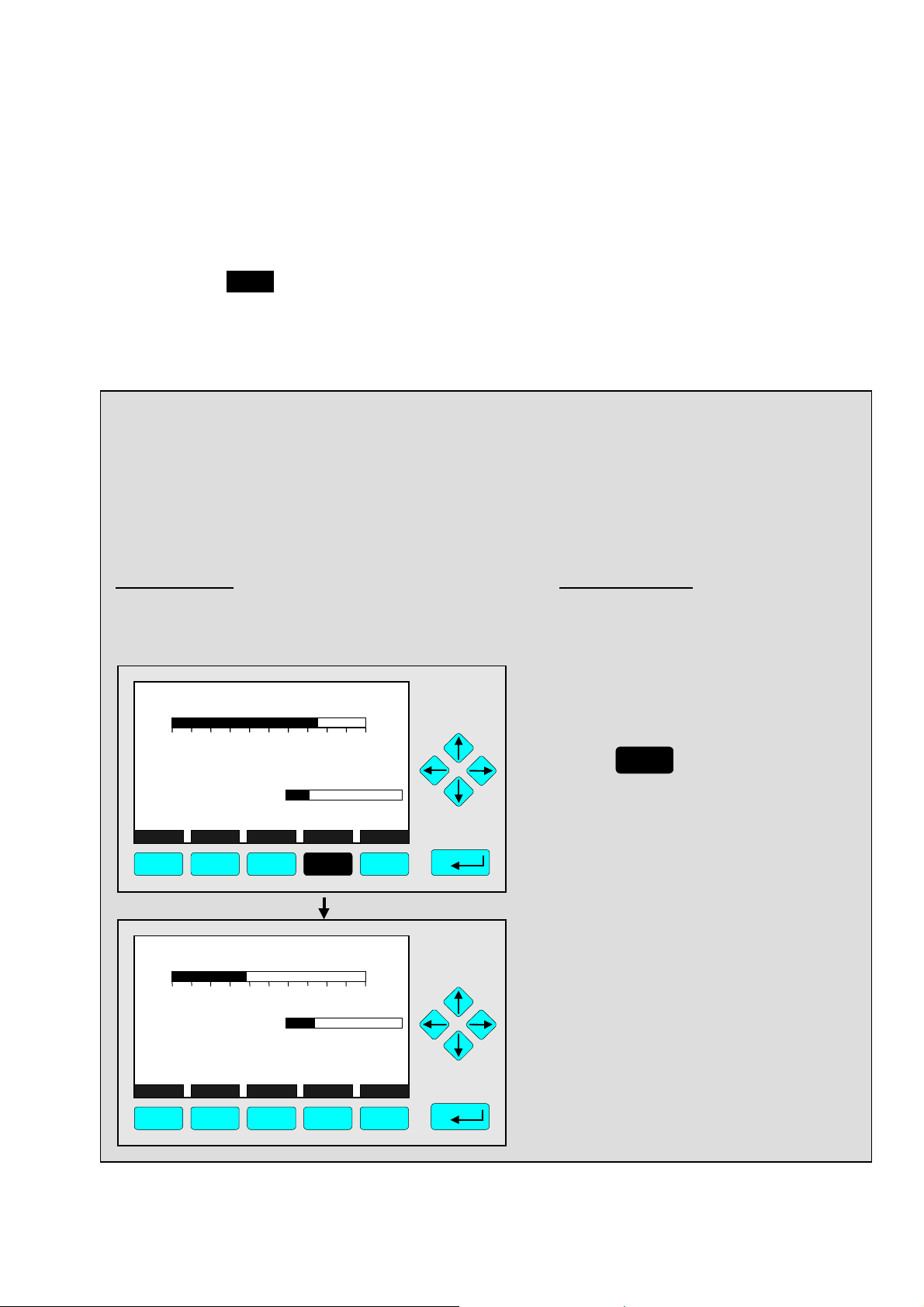
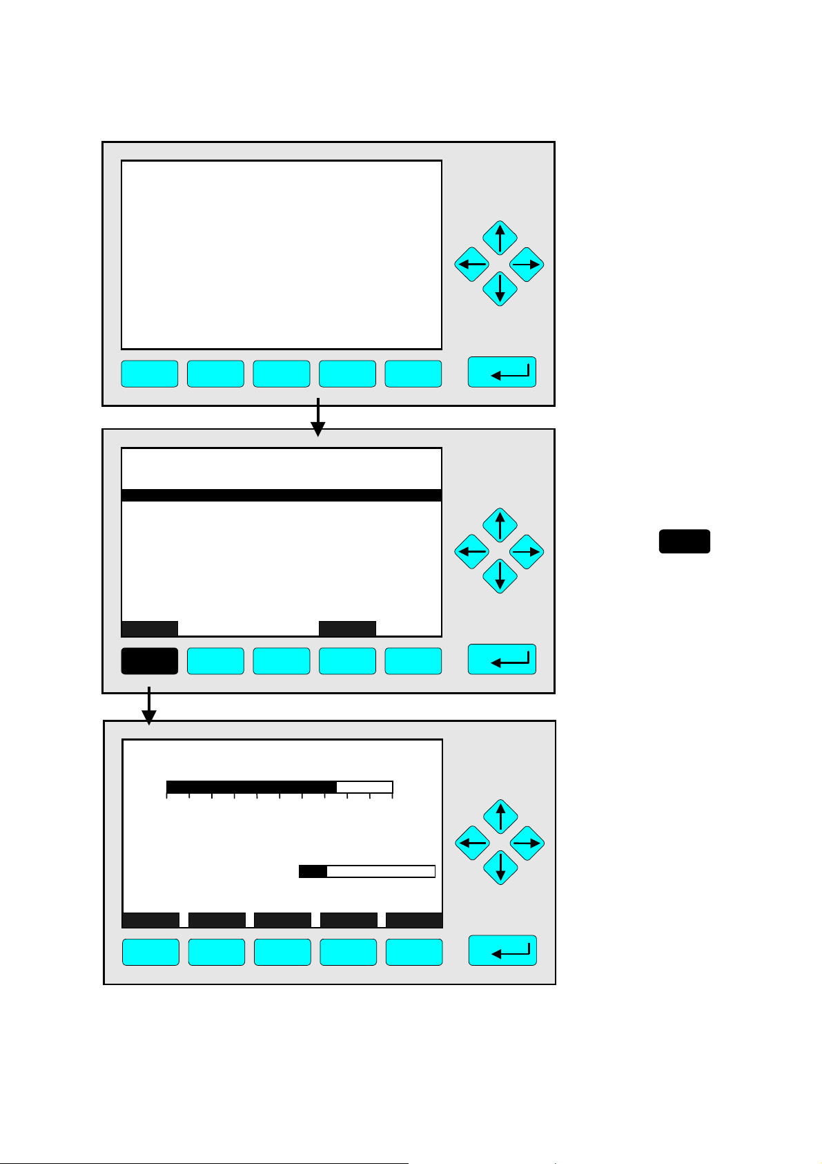
4.3 Multi Component Display
Change of Channel
⇒ Switch to the
multi component display
F1
Press
Failures: No
Maintenance-Requests: No
Temperature: 20.0 °C
Operation: Ready
Display Status... Main... Channel BasicCal
0.0 100.0
F1 F2 F3 F4 F5
Notes:
•
Displaying multiple
channels is only possible,
if the TFID is connected to
other modules / analyzers.
•
You can open the multi
component display from
any single component
display.
⇒ Enable the "selecting
37.50
95.00
333.0
150.0
20.00
Select Status... Tags Off
F1 F2 F3 F4 F5
TFID
ppm Propane
MLT25/CH1
ppm CO
MLT25/CH2
ppm SO2
MLT25/CH3
ppm NO
MLT25/CH4
%O2
[1]
0.00 250.00
0.00 500.00
0.00 150.00
0.00 100.00
[2]
[2]
[2] F.S.
[2]
LCDReset
50.000.00
symbol":
>
F1
Press
or
Notes:
•
Each bargraph shows the
start and endpoint of range
of the corresponding
channel. (F.S. = f
•
The number in paren-
ull scale)
theses shows the number
of the selected range.
Option:
Using the F3 -key you can
fade out or in the tags.
⇒ Select any channel
37.50
95.00
333.0
150.0
20.00
Select Status... Tags Off
F1 F2 F3 F4 F5
TFID
ppm Propane
MLT25/CH1
ppm CO
MLT25/CH2
ppm SO2
MLT25/CH3
ppm NO
MLT25/CH4
%O2
[1]
0.00 250.00
0.00 500.00
0.00 150.00
0.00 100.00
[2]
[2]
[2] F.S.
[2]
LCDReset
50.000.00
Press
as often as necessary to
place the
line you want to select.
Example:
Change from
CH
4
CO (MLT channel 1)
>
-mark at the
(TFID) to
or
ETC00612(1) [NGA-e (TFID SW 3.4.X)] 02/01
NGA 2000
4 - 17

37.50
95.00
333.0
150.0
20.00
Select Status... Tags Off
F1 F2 F3 F4 F5
TAG
TFID
ppm Propane
MLT25/CH1
ppm CO
MLT25/CH2
ppm SO2
MLT25/CH3
ppm NO
MLT25/CH4
%O2
[1]
0.00 250.00
0.00 500.00
0.00 150.00
0.00 100.00
[2]
[2]
[2] F.S.
[2]
95.00 ppm CO
0250
Temperature: 25.0 °C
Maintenance-Requests: No
Any_Alarms: No
Operation: Ready
Display Status... Main... Channel BasicCal
F1 F2 F3 F4 F5
Range: 2
0.0 100.0
50.000.00
LCDReset
⇒ Switch to the single
component display of
the selected channel
Press
F1
Note:
Pressing F5 resets the LCDbrightness and contrast to
factory default settings (see
also section 7).
⇒ Single component
display of the
selected channel
4 - 18
NGA 2000
ETC00612(1) [NGA-e (TFID SW 3.4.X)] 02/01

TAG
37.50 ppm CH4
0.00 50.00
Range: 1
4.4 Calibration Procedure Status
⇒ Open the
menu "Analyzer
Basic Controls
(calibration) &
Setup"
Failures: No
Maintenance-Requests: No
Temperature: 20.0 °C
Operation: Ready
Display Status... Main... Channel BasicCal
0.0 100.0
Press
F5
F1 F2 F3 F4 F5
⇒ Enter the submenu
TAG
-- Analyzer Basic Controls (calibration) and Setup --
Calibration procedure state...
Start zero calibration procedur e !
Start span calibration procedure !
Check calibration deviation: Enabled
Range number: 1
Span gas: 46.00 ppm
Range upper limit: 50.00 ppm
Operation status: Ready
Measure Status... Channel Back...
37.50 ppm
Valves...
F1 F2 F3 F4 F5
TAG
-- Calibration Procedure State --
Procedure state: Ready
Maximum remaining procedure time: 0 s
Valve position: Samplegas
Concentration in span gas units: 37.50 ppm
Last zero calibration: Success
Last span calibration: Success
Last zero calibration was: Fri 05-29-1998 13:32:06
Last span calibration was: Fri 05-29-1998 13:37:23
Successful zero+span calibrated
Measure Cancel ! Back... More...
37.50 ppm
1+2+3+4
F1 F2 F3 F4 F5
"Calibration
Procedure State"
Press
Options:
Softkey F5 opens a
submenu where you can
close all valves or set up
each valve separately for:
•
zero gas
•
span gas
•
sample gas
•
test gas.
(See section 4.7,
pg. 4-29...)
⇒ Open the menu page
"Calibration
Deviations"
Press
F5
ETC00612(1) [NGA-e (TFID SW 3.4.X)] 06/01
NGA 2000
4 - 19

TAG
f
-- Calibration Deviations --
Dev iation from zer o:
Sum of zero deviations:
Dev iation from span:
Sum of s pan deviation s:
Measure
Channel
Back...
-0. 05 ppm
-0. 41 ppm
-0. 14 ppm
-0. 57 ppm
37.50 ppm
Flow ...
F1 F2 F3 F4 F5
TAG
37.50 ppm CH4
0.00 50.00
Failures: No
Maintenance-Requests: No
Temperature: 20.0 °C
Operation: Ready
Display Status... Main... Channel BasicCal
F1 F2 F3 F4 F5
Range: 1
0.0 100.0
⇒ Return to the single
component display o
the current channel
F1
Press
Options:
•
A basic calibration procedure will reset the deviations to 0.00 (see section
5.1.1, p. 5-18: Advanced
Calibration Methods - Start
basic calibration procedure
!)
•
Using F3 you can change
to other available channels
to check their "Calibration
Deviations".
•
The function key F4
returns back to the menu
"Calibration Procedure
Status".
⇒ Back at the si ngle
component display
4 - 20
NGA 2000
ETC00612(1) [NGA-e (TFID SW 3.4.X)] 06/01

TAG
37.50 ppm CH4
0.00 50.00
Failures: No
Maintenance-Requests: No
Temperature: 20.0 °C
Operation: Ready
Display Status... Main... Channel BasicCal
F1 F2 F3 F4 F5
TAG
-- Analyzer Basic Controls (calibration) & Setup --
Calibration procedure state...
Start zero calibration procedure !
Start span calibration procedure !
Check calibration deviation: Enabled
Range number: 1
Span gas: 46.00 ppm
Range upper limit: 50.00 ppm
Operation status: Ready
Measure Status... Channel Back...
F1 F2 F3 F4 F5
TAG
-- Basic Controls and Setup --
Calibration procedure status...
Start zero calibration procedure !
Start span calibration procedure !
Check calibration deviation: Enabled
Range number: 1
Span gas: 46.00 ppm
Range upper limit: 50.00 ppm
Operation status: Ready
Measure Status... Channel Back...
F1 F2 F3 F4 F5
ETC00612(1) [NGA-e (TFID SW 3.4.X)] 02/01
Range: 1
0.0 100.0
37.50 ppm
Valves...
37.50 ppm
Valves...
NGA 2000
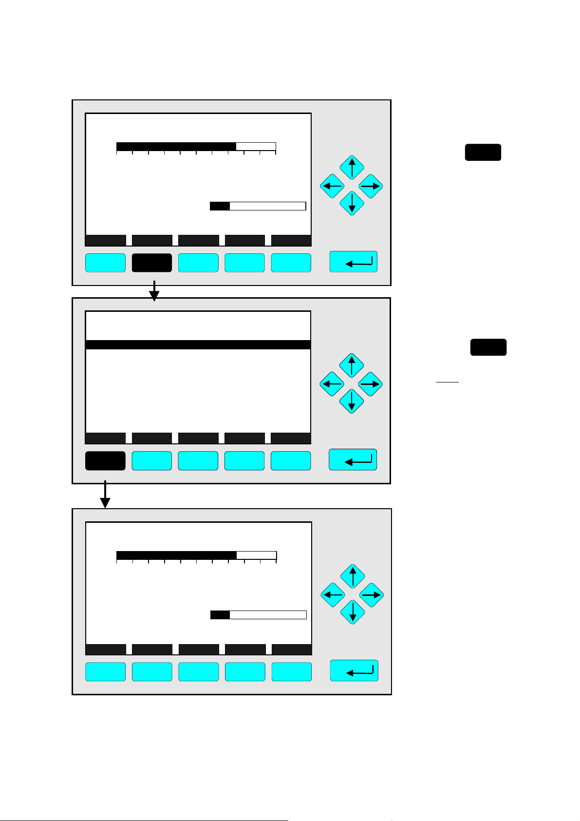
4.5 Zero Calibration
⇒ Open the menu
"Analyzer Basic
Controls (calibrations) & Setup"
F5
Press
Caution:
Before starting zero
calibration make sure that
zero gas is available !
(See also section 5.1.1,
pg. 5-5... !)
Note
:
The zeroing of all measurement ranges of the selected
channel is running
simultaneously.
⇒ Highl i ght the
line "Start zero
calibration
procedure !"
Press
get the line "Start zero
calibration procedure !"
highlighted.
⇒ Start the zero
calibration
Press
or
once to
4 - 21

⇒ Confirm to start the
TAG
-- Confirmation Required --
Do you really want to do this ??
Press "Yes" or "Back..."
Yes Back...
F1 F2 F3 F4 F5
37.50 ppm
zero calibration
F2
Press
the zeroing immediately.
Option:
Press the F4 -key if you want
to cancel the procedure.
Notes:
•
The display of this message
depends on the setup in
the expert controls & setup
(see 5.1.8 pg. 5-49).
•
The next 3 illustrations
show the displays you can
see after starting the
zeroing procedure.
to start
TAG
-- Calibration Procedure State --
Procedure state: Purging1-Wait
Maximum remaining procedure time: 8 s
Valve position: Zerogas
Concentration in span gas units: 37.50 ppm
Last zero calibration: Success
Last span calibration: Success
Last zero calibration was: 13:32:06 July 27, 1999
Last span calibration was: 13:38:46 July 28, 1999
Successful zero+span calibrated ranges: 1+2+3+4
Measure Cancel ! Back... More...
F1 F2 F3 F4 F5
Channel
37.50 ppm
⇒ Zeroing:
1. Purging-Wait
Notes:
•
The procedure time depends on the parameters
entered for purge time
(see section 5.1.1 pg. 5-10).
•
The purge time must be long
enough to get a stable signal
before calibration.
•
You can cancel the run-ning
calibration procedure at any
time pressing the
F2 -key.
⇒ Zeroing:
TAG
-- Calibration Procedure State --
Procedure state: Zeroing-Wait
Maximum remaining procedure time: 97 s
Valve position: Zerogas
Concentration in span gas units: 3.13 ppm
Last zero calibration: Success
Last span calibration: Success
Last zero calibration was: 13:32:06 July 27, 1999
Last span calibration was:
Successful zero+span calibrated ranges: 1+2+3+4
Measure Cancel ! Back... More...
Channel
13:38:46 July 28, 1999
3.13 ppm
2. Zeroing-Wait
Note:
The procedure time depends on the parameters
entered for stability time and
averaging time.
(see section 5.1.1 pg. 5-10)
F1 F2 F3 F4 F5
4 - 22
NGA 2000
ETC00612(1) [NGA-e (TFID SW 3.4.X)] 02/01

TAG
-- Calibration Procedure State --
Procedure state: Ready
Maximum remaining procedure time: 0 s
Valve position: Samplegas
Concentration in span gas units: 0.00 ppm
Last zero calibration: Success
Last span calibration: Success
Last zero calibration was:
Last span calibration was:
Successful zero+span calibrated ranges: 1+2+3+4
Measure
F1 F2 F3 F4 F5
Cancel !
13:32:06 July 27, 1999
13:38:46 July 28, 1999
Channel
Back... More...
TAG
0.00 ppm CH4
0.00 50.00
Failures: No
Maintenance-Requests: No
Temperature: 20.0 °C
Operation: Ready
Range: 1
0.0 100.0
0.00 ppm
4.5 Zero Calibration
⇒ Zeroing:
3. Zeroing Done
⇒ Return to the
single component
display of the
current channel
F1
Press
Options:
•
F4 -key: Return to the
menu "Analyzer Module
Calibration".
•
F5 -key: Open menu
"Calibration Deviations".
⇒ Single component
display appears
when zeroing has
finished.
Display Status... Main... Channel BasicCal
F1 F2 F3 F4 F5
ETC00612(1) [NGA-e (TFID SW 3.4.X)] 02/01
NGA 2000
4 - 23

4 - 24
NGA 2000
ETC00612(1) [NGA-e (TFID SW 3.4.X)] 02/01

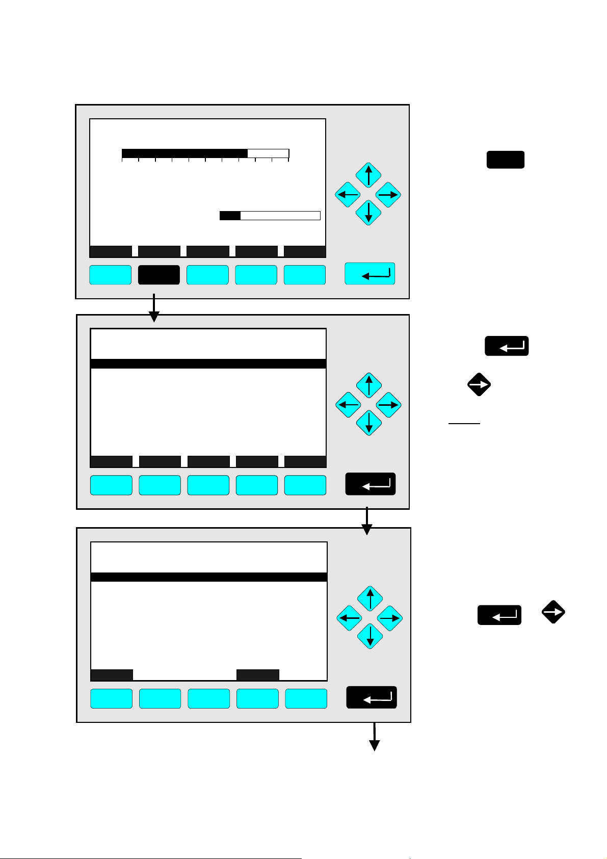
4.6 Span Calibration/Basic Parameters
TAG
37.50
Failures:
Maintenance-Requests: No
Temperature:
Operation:
Display Status...
F1 F2 F3 F4 F5
0.00
Range: 1
20.0 °C
Ready
No
0.0 100.0
Main...
ppm CH4
50.00
Channel
BasicCal
Use the menu
"Analyzer Basic Controls (calibration) & Setup" to view
calibration status, start zero / span calibration and set up basic
parameters like "check calibration deviation", "(measuring)
range number", "span gas" and "range upper limit (end of
range)".
Operating this menu is shown on the basis of an example
(Start span calibration procedure). All other procedures are
executed similar.
See additional notes at the end of this chapter too (pg. 4-28)!
TAG
-- Analyzer Basic Controls (calibration) & Setup --
Calibration procedure state...
Start zero calibration procedure !
Start span calibration procedure !
Check calibration deviation: Enabled
Range number: 1
Span gas: 46.00 ppm
Range upper limit: 50.00 ppm
Operation status: Ready
Measu re Status... Channel Back...
F1 F2 F3 F4 F5
ETC00612(1) [NGA-e (TFID SW 3.4.X)] 06/01
37.50 ppm
Valves...
NGA 2000
⇒ Open the
menu "Analyzer
Basic Controls
(calibration) & Setup"
Press
F5
Caution:
Before starting span
calibration, prove that
span gas with correct
concentration is available !
(See also section 5.1.1,
pg.5-6... !)
⇒ Highlight the line
"Start span calibration procedure !"
Press
get the line "Start span
calibration procedure !"
inverse.
Notes:
•
Normally, all
measurement ranges of
the same channel are
calibrated
simultaneously.
•
To calibrate separately
you have to change the
parameters (see 5.1.1
pg. 5-10).
twice to
4 - 25

⇒ Start
TAG
-- Basic Controls and Setup --
Calibration procedure status...
Start zero calibration procedure !
Start span calibration procedure !
Check calibration deviation:
Range number: 1
Span gas: 46.00 ppm
Range upper limit: 50.00 ppm
Operation status: Ready
Measure Status... Channel Back...
F1 F2 F3 F4 F5
37.50 ppm
Enabled
Valves...
span calibration
Press
or
TAG
-- Confirmation Required --
Do you really want to do this ??
Press "Yes" or "Back..."
Yes Back...
F1 F2 F3 F4 F5
37.50 ppm
⇒ Confir m st art i ng
span calibration
Press
the spanning immediately.
Option:
Press the F4 -key if you want
to cancel the procedure.
Notes:
•
The display of this message
depends on the setup in
the expert controls &
setup.
(see 5.1.8 p. 5-49)
•
The 3 following illustrations
show the displays you can
see after starting the
spanning procedure.
F2
to start
TAG
-- Calibration Procedure State --
Procedure state: Purging1-Wait
Maximum remaining procedure time: 8 s
Valve position: Spangas 1
Concentration in span gas units: 37.50 ppm
Last zero calibrati on: Success
Last span calibration: Success
Last zero calibrati on was: 13:32:06 July 27, 1999
Last span calibration was: 13:38:46 July 28, 1999
Successful zero+span calibrated ranges: 1+2+3+4
Measure Cancel ! Back... More...
F1 F2 F3 F4 F5
Channel
37.50 ppm
⇒ Spanning:
Notes:
•
The procedure time depends on the parameters
entered for purge time
(see 5.1.1 p. 5-10).
•
The purge time must be
long enough to get a
stable signal before
starting calibration.
•
You can cancel the
running calibration
procedure at any time with
the F2 -key.
1. Purging-Wait
4 - 26
NGA 2000
ETC00612(1) [NGA-e (TFID SW 3.4.X)] 06/01

y
TAG
TAG
Procedure state: Spanning-Wait
Procedur e s t atus: Spanning-Wait
Maximum remaining procedure time: 8 s
Maximum r e maining procedu re time: 108 s
Valve position: Spangas 1
Valve position: Spangas-1
Concentration in span gas units: 37.50 ppm
Concentr ation in span ga s units: 43.57 ppm
Last zero calibration: Success
Last zero calibrat i on: Success
Last span calibration: S uccess
Last span calibration: Success
Last zero calibration was: 13:32:06 July 27, 1999
Last zero calibration was: 09:21:34 July 27, 1999
Last span calibration was: 13:38:46 July 28, 1999
Last span calibration was : 13:37:23 July 27, 1999
Successful zero+span calibrated ranges: 1+2+3+4
Successful zero+span calibrated ranges: 1+2+3+4
Measure Cancel ! Back... More...
Measure Cancel ! Back... More...
-- Calibration Procedure State --
-- Calibration Proce dure Status --
---------------------- Results ----------------------
Channel
4.6 Span Calibration/Basic Parameters
⇒ Spanning:
37.50 ppm
43.57
2. Spanning-Wait
Note:
The procedure time depends on the parameters
entered for stability time
and averaging time.
(see 5.1.1 p.5-10)
F1 F2 F3 F4 F5
F1 F2 F3 F4 F5
TAG
-- Calibration Procedure State --
Procedure state:
Maximum remaining procedure time:
Valve position:
Concentration in span gas units:
Last zero calibration: Success
Last span calibration:
Last zero calibrat i on was: 13:32:06 July 27, 1999
Last span calibr at ion was: 13:38:46 July 28, 1999
Successful zero +span calibrated ranges:
F1 F2
Measure Cancel !
Channel
F3
Back... More...
F4
Samplegas
37.50 ppm
37.50 ppm
Read
8 s
Success
1+2+3+4
F5
⇒ Spanning:
3. Spanning-Ready
⇒ Return to the
single component
display of the
current channel
Press
Options:
•
F4 -key: Return to the
menu "Analyzer Module
Calibration".
•
F5 -key: Enter the menu
"Calibration Deviations".
F1
TAG
50.00 ppm CH4
0.00 50.00
Range: 1 F.S.
⇒ Single component
display appears
when spanning has
finished.
Failures: No
Maintenance-Requests: No
Temperature: 20.0 °C
Operation: Ready
Display Status... Main... Channel BasicCal
0.0 100.0
F1 F2 F3 F4 F5
ETC00612(1) [NGA-e (TFID SW 3.4.X)] 06/01
NGA 2000
4 - 27

Notes
Some notes about how to operate the "Analyzer Basic Controls (calibration) & Setup" menu:
TAG
-- Analyzer Basic Controls (calibrati o n) & Setup --
Calibration procedure state...
Start zero calibration procedure !
Start span calibration procedure !
Check calibration deviation: Enabled
Range number: 1
Span gas: 46.00 ppm
Range upper limit: 50.00 ppm
Operation status: Ready
Measure Status... Channel Back...
F1 F2 F3 F4 F5
37.50 ppm
Valves...
Editing variables
♦
Press ↑↑↑↑ -key or ↓↓↓↓ -key to highlight the appropriate line.
♦
Select the variable to be edited by pressing
↵↵↵↵
-key or →→→→ -key.
If editing is not allowed, check “Application for Basic Controls menu” (5.1.8; pg. 5-52)
to allow editing this variable.
♦
Adjust the variable using the ←←←← -key or →→→→ -key.
Define another range or enable/disable calibration deviation check using the ↑↑↑↑- or ↓↓↓↓ -key.
♦
Enter the parameter using the
↵↵↵↵
-key or return to the previous value pressing F2.
Line of variables „Check calibration deviation“:
Enables or disables the stability and tolerance control during calibration.
Line of variables „Range number“:
Use this variable to select the measuring range (1 to 4).
Line of variables „Span gas“:
Insert the span gas value. Inadmissible high span gas values (outside the linearization) are
not accepted. (Take into account the lowest and highest end of range ! Span gas should be
within 70 to 100 % of the upper limit !).
Line of variables „Range upper limit“:
Enter the end of range (upper limit). Inadmissible high upper limits (outside the linearization)
are not accepted.
4 - 28
NGA 2000
ETC00612(1) [NGA-e (TFID SW 3.4.X)] 06/01

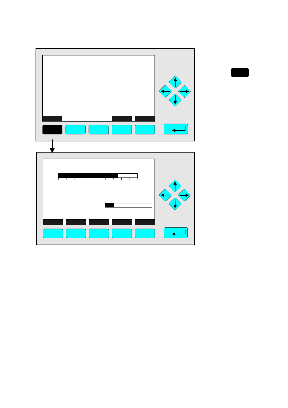
4.7 Activate Zero Gas, Span Gas, Sample Gas or Test Gas
Close all Valves
TAG
37.50
Failures:
Maintenance-Requests: No
Temperature:
Operation:
Display Status...
F1 F2 F3 F4 F5
0.00
20.0 °C
Ready
Range: 1
No
Main...
0.0
ppm CH4
50.00
Channel BasicCal
100.0
TAG
-- Analyzer Basic Controls (calibration) & Setup --
Calibration procedure state...
Start zero calibration procedure !
Start span calibration procedure !
Check calibration deviation:
Range number:
Span gas:
Range upper limit:
Operation status:
Measure Status... Channel Back...
F1 F2 F3 F4 F5
37.50 ppm
Enabled
1
46.00 ppm
50.00 ppm
Valves...
Ready
TAG
-- Set Gas Valves --
Flow zero gas !
Flow span gas !
Flow sample gas !
Flow test gas !
Close all valves !
Valve position: Sample gas
Operation state: Ready
Measu re Status... Channel Back...
F1 F2 F3 F4 F5
37.50 ppm
Flow...
⇒ Open the
menu "Analyzer
Basic Controls
(calibration) &
Setup"
Press
F5
Caution:
Before starting zero gas
flow, make sure zero gas is
available !
(See also section 5.1.1,
pg.5-5... !)
⇒ Enter the menu
"Set Gas Valves"
F5
Press
⇒ Start “Flow zero
gas !”
Press
or
Starting this function will
open the zero gas valve as
current gas valve.
ETC00612(1) [NGA-e (TFID SW 3.4.X)] 02/01
NGA 2000
4 - 29

⇒ Confir m t o open zero
TAG
37.50 ppm
gas valve
Press
to start the zero
-- Confirmation Required --
Do you really want to do this ??
Press "Yes" or "Back..."
Yes Back...
F1 F2 F3 F4 F5
gas flow immediately.
Option:
Press the F4 -key if you
want to cancel the
procedure and return to the
menu "Set Gas Valves".
Note:
Whether this message
appears or not depends on
the setup in the expert
controls & setup
(see 5.1.8, pg. 5-49).
F2
TAG
37.50 ppm
⇒ Process is start ed
Note:
This message is displayed
- S U C C E S S -
- The selected function has been started/executed (Wait a moment...)
when the function has been
started. After a moment the
display will return
automatically to the menu
"Set Gas Valves".
F1 F2 F3 F4 F5
TAG
-- Set Gas Valves --
Flow zero gas !
Flow span gas !
Flow sample gas !
Flow test gas !
Close all valves !
Valve position: Sample gas
Operation state:
Measure Status... Channel Back...
F1 F2 F3 F4 F5
Ready
37.50 ppm
Flow...
⇒ Additional options
•
Start flow span gas,
sample gas or test gas !
•
Close all valves !
•
F3 -key: Switch to another
available channel to set
gas valves.
•
F4 -key: Return to the
menu "Basic Controls and
Setup " to start zeroing or
spanning.
•
F1 –key: Return to Single
Component Display
4 - 30
NGA 2000
ETC00612(1) [NGA-e (TFID SW 3.4.X)] 02/01

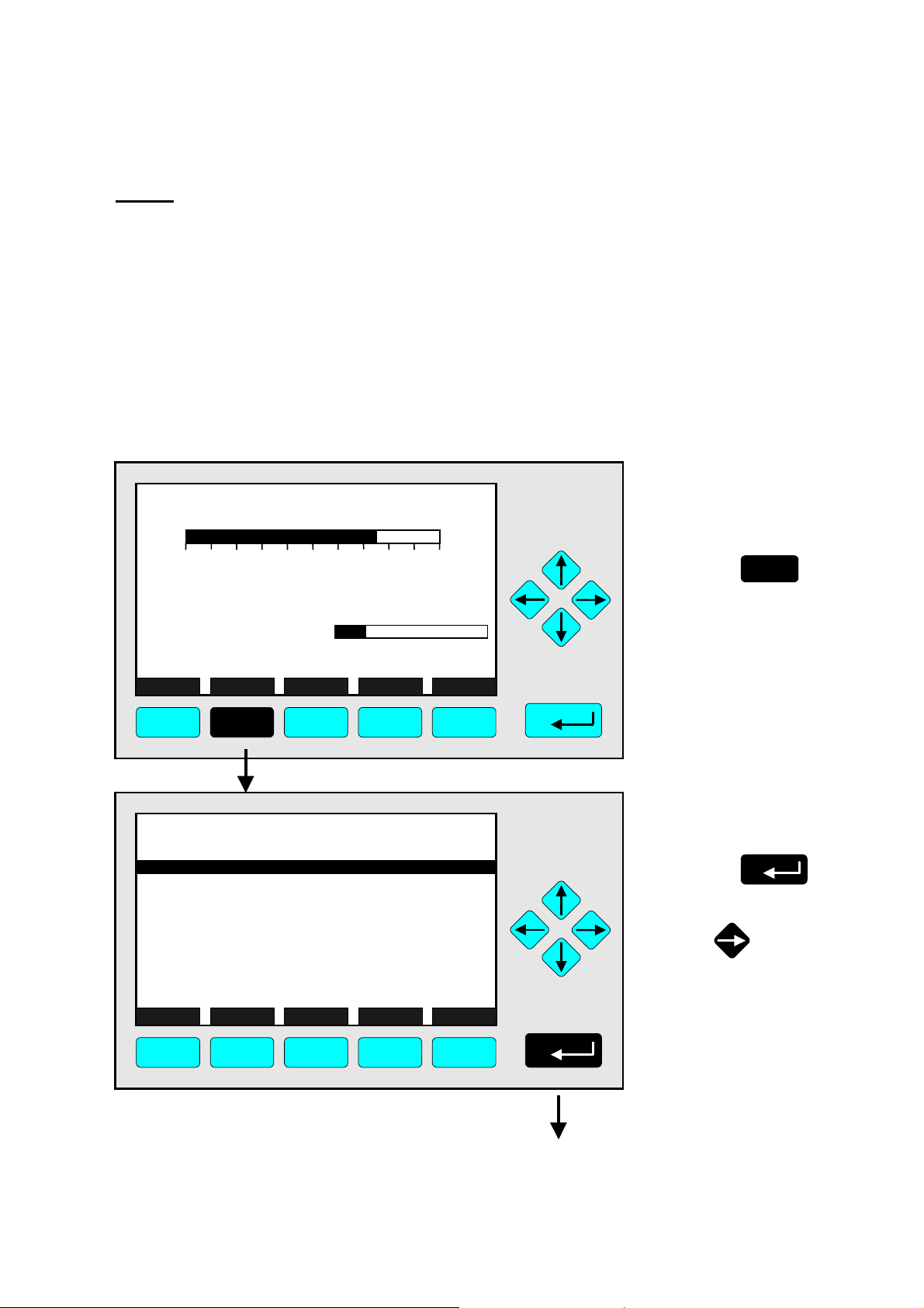
4.8 Flow measurement
TAG
37.50
Failures:
Maintenance-Requests: No
Temperature:
Operation:
Display Status...
0.00
Ready
Range: 1
No
20.0 C
Main...
ppm CH4
0.0
50.00
Channel BasicCal
100.0
⇒ Open the
menu "Analyzer
Basic Controls
(calibration) &
Setup"
F5
Press
F1
F2
F3 F4 F5
TAG
-- Analyzer Basic Controls (calibrati o n) & Setup --
Calibration procedure state...
Start zero calibration procedure !
Start span calibration procedure !
Check calibration deviation: Enabled
Range number: 1
Span gas: 46.00 ppm
Range upper limit: 50.00 ppm
Operation status: Ready
Measure Status... Channel Back...
F1 F2 F3 F4 F5
37.50 ppm
Valves...
⇒ Enter the menu
"Set Gas Valves"
F5
Press
⇒ Open the menu
TAG
Flow zero gas !
Flow span gas !
Flow sample gas !
Flow test gas !
Close all valves !
-- Set Gas Valves --
37.50 ppm
"Flow
Measurement"
F5
Press
Valve position: Sample gas
Operation state: Ready
Measu re Status... Channel Back...
Flow...
F1 F2 F3 F4 F5
ETC00612(1) [NGA-e (TFID SW 3.4.X)] 02/01
NGA 2000
4 - 31

⇒ Set Flow unit
TAG
0.00 pp m
-- Flow Measurement --
Unit: ml/min
Flow measurement is: Valid
Flow: 1.0 ml/min
Measure Channel Back...
F1 F2 F3 F4 F5
Press the ↵↵↵↵ -key or the
♦
→→→→ -key to select the
variable.
♦
Select the unit using the
↑↑↑↑ -key or the ↓↓↓↓ -key.
Options: ml/min, l/min
♦
Confirm your adjustment
using the ↵↵↵↵
cancel and return to the
previous value pressing
F2.
Note:
If a flow sensor is not
installed choosing this menu
will display a message
instead of the shown menu.
♦
Press F4 to return to the
previous page.
-key or
TAG
-- Set Gas Valves --
Flow zero gas !
Flow span gas !
Flow sample gas !
Flow test gas !
Close all valves !
Valve position: Sample gas
Operation state: Ready
Measu re Status... Channel Back...
37.50 ppm
Flow...
⇒ Return to the single
component display.
Press
F1
F1 F2 F3 F4 F5
4 - 32
NGA 2000
ETC00612(1) [NGA-e (TFID SW 3.4.X)] 02/01

5 Analyzer and I/O, Expert Controls & Setup
If you press the
↵↵↵↵
-key or the →→→→ -key in the line "Analyzer and I/O, expert controls
& setup..." of the "M ain Menu", the following menu will open:
TAG
-- Analyzer and I/O Expert Controls & setup --
Analyzer module controls...
System & network I/O module controls...
Analyzer module setup...
System & network I/O module setup...
(Note: Controls & setup are identical for MLT/TFID)
Measu re Channel Back...
F1 F2 F3 F4 F5
37.50 ppm
In the menu "Expert Module Configuration" you can enter several submenus to set up
parameters for measurement and calibration of your analyzer / analyzer module. Moreover
you can set up the configuration for external modules. W hich parts of these menus are
important for you depends on the configuration of your NGA 2000 system.
The following table will give you a short overview about the contents of the menus:
Menu Important Contents Section/Page
Analyzer module controls... ⇒ See "Analyzer module setup" and note below!
System & network I/O
module controls...
⇒ Configuration of the SIO and of the DIO's
installed in a platform or in a TFID/MLT
∗ 5.2
pg. 85 - 100
analyzer (System I/O's)
Analyzer module setup...
⇒ Set up of Measurement and calibration
⇒ SIO & DIO’s configuration installed in
∗ 5.1
pg. 3 - 84
TFID/MLT AM’s (Local SIO/DIO)
⇒ Programmable logic control (PLC)
⇒ Programmable calculators
System & network I/O
⇒ Set up of Network I/O modules
∗ 5.3 / pg. 101
module setup...
Note:
All submenus of "Analyzer module controls..." are the same as those of "Analyzer module
setup..." if you use a TFID/MLT analyzer / analyzer module ! If your analyzer is not of such
type the submenus of "Analyzer module controls..." and "Analyzer module setup..." will
look different. Refer to the corresponding software manuals.
ETC00612(1) [NGA-e (TFID SW 3.4.X)] 02/01
NGA 2000
5 - 1

Structure of chapter five:
At the beginning of each section you will find the way to a defined submenu in the
TFID/MLT software: Starting from the line "Analyzer and I/O, expert controls & setup" in
the "Main Menu" the way through the menus is described giving the menu lines you have
to enter sequentially to reach the submenu. At the end of this description you will find an
illustration of the final submenu screen followed by set up instructions and explanations.
Sometimes the illustration may be completed by sketches or additional menu pictures.
Example: You want to set up the calibration parameters for the calibration procedure of
the analyzer module.
Main Menu — Analyzer and I/O, expert controls & setup
↓↓↓↓
Analyzer module setup
↓↓↓↓
Calibration parameters
↓↓↓↓
Calibration procedure setup
↓↓↓↓
TAG
-- Calibration Procedure Setup --
Purge time: 10 s
Procedure times-out after: 120 s
Analog output during calibration: Tracking
Span ranges: Together
Valve position: Samplegas
Stability time: 30 s
Averaging time: 5 s
Measure Channel Back...
F1 F2 F3 F4 F5
In the menu "Calibration Procedure Setup" you can set the parameters for the calibration
procedures zeroing and spanning.
Detailed explanations and instructions will follow later in this chapter!
95.00 ppm
5 - 2
NGA 2000
ETC00612(1) [NGA-e (TFID SW 3.4.X)] 02/01

5.1 Analyzer Module Setup
Main Menu — Analyzer and I/O, expert controls & setup
↓↓↓↓
Analyzer module setup
↓↓↓↓
TAG
-- Analyzer Module Setup and Control s (1/3) --
Calibration parameters...
Alarm par amet ers.. .
Range parameters...
Cross interferenc e c ompensation.. .
Linearization...
Progr ammable logic c ontrol (PLC) ...
Programmable calculator...
Measure men t display configura tion...
Acknowledge m ent of stat us reports...
General conc entr ation measurement setup...
Measure ManData Channel
Back...
95.00 ppm
More...
F1 F2 F3 F4 F5
TAG
-- Analyzer Module Se tup and Controls (2/3) --
Concent ration peak mea s ure ment ...
Differential measurement...
Gas flow set up...
Pres sure compensation...
Flow mea sure ment ...
Temp eratur e measure ment. ..
Load/save configur ation (AM )...
Local I /O module set up.. .
Delay and average...
Special functions...
Measure
Channel
Back...
95.00 ppm
F1 F2 F3 F4 F5
TAG
-- Analyzer Module Set up and Con trols (3/3) --
AK protocol c ommunic at ion.. .
95.00 ppm
More...
Measure
F1 F2 F3 F4 F5
ETC00612(1) [NGA-e (TFID SW 3.4.X)] 06/01
Back...
NGA 2000
5 - 3

Starting from the menu "Analyzer Module Setup and Controls" you can enter all menus
and submenus of the expert configuration level via the corresponding menu lines.
Entering menus and submenus:
♦
Select the menu line you want using the ↓↓↓↓ -key or the ↑↑↑↑ -key.
If necessary: Enter the next menu page using the F5 -key (More...)
♦
Enter the corresponding menu/submenu using the
↵↵↵↵
-key or the →→→→ -key.
Menu "Load Factory Configuration" (Softkey ManData):
This function is used to delete the analyzer module RAM data and load factory default
settings from the Flash-EPROM. Since TFID is not a analyzer module enter the menu
"Load/Save configuration (CM/MCA" in the menu "System Configuration and Diagnostics"
for loading control module factory default settings. For more information refer to 6.2,
pg. 6-6.)
If you press the F2 -key ( M anData) i n the menu "Anal y zer Module Setup and Controls (1/3)",
anyway you will see the following display:
TAG
95.00 ppm
- S O R R Y -
Only available for an analy zer module.
Please u se the syst em le vel functions.
(Press softkey “>>>“)
Back...
>>>
F1 F2 F3 F4 F5
Pressing F5 as asked will take you to directly to the menu "Load/Save configuration
(CM/MCA)" as described above.
F4 returns you back to the previous menu.
5 - 4
NGA 2000
ETC00612(1) [NGA-e (TFID SW 3.4.X)] 06/01

5.1 Analyzer Module Setup
5.1.1 Calibration Parameters
Main Menu — Analyzer and I/O, expert controls & setup
↓↓↓↓
Analyzer module setup
↓↓↓↓
Calibration parameters
↓↓↓↓
TAG
-- Calibration Parameters --
Zero gases...
Span gases...
Tolerances...
Calibration procedure setup...
Time controlled calibration...
Analyzer basic controls (calibration) & setup...
Advanced calibration methods...
Range and calibration control: Manual
Measur e Channel Back...
F1 F2 F3 F4 F5
37.50 ppm
From the menu "Calibration Parameters" you can enter several submenus to set up zero
and span gas calibration parameters and to start the di fferent calibrati on methods.
Enter submenus:
♦
Select the menu line you want using the ↓↓↓↓ -key or the ↑↑↑↑ -key.
♦
Enter the submenu pressing the
↵↵↵↵
-key or the →→→→ -key.
♦
Select the parameter with the ↑↑↑↑ -key or the ↓↓↓↓ -key, switch into EDIT mode using the
←←←← - key or →→→→ - key and change the value using the ↑↑↑↑ -key or ↓↓↓↓ -key
♦
Confirm the new value using the
↵↵↵↵
-key or
cancel and return to the previous value pressing F2.
Function keys:
♦
F1: Return to the single component display!
♦
F3: This key is shown but not active!
♦
F4: Return to the previous menu page!
Line of variables "Range and calibration control":
The parameter selected in this line is valid for the autoranging control of the current
channel. You may set it in the menu "Range parameters" too. Refer to chapter 5.1.3, pg.
5-25 for explanation of parameter setting!
ETC00612(1) [NGA-e (TFID SW 3.4.X)] 06/01
NGA 2000
5 - 5

5.1 Analyzer Module Setup
5.1.1 Calibration Parameters – Span gases
Main Menu — Analyzer and I/O, expert controls & setup
↓↓↓↓
Analyzer module setup
↓↓↓↓
Calibration parameters
↓↓↓↓
Span gases
↓↓↓↓
TFID-R1
Actual span ga s conc entration:
Spangas range -1:
Spangas range -2:
Spangas range -3:
Spangas range -4:
Span gas unit:
"ppm" - - > "mg/Nm3" conversion factor:
Concent r ation in span g as units:
Measure
-- Span Gas Def inition (1/2) --
37.50 ppm
Back...
50.00 ppm
50.00 ppm
250.0 ppm
2500 pp m
10000 pp m
1.970
37.50 ppm
More...
ppm
F1 F2 F3 F4 F5
In the menu "Span Gas Definition (1/2)" you may set the actual span gas concentration,
the default span gas value for each range of the current channel and the desired
components span gas unit (e.g. Methane, Propane). The span gas concentration of each
range should be a value between 70 and 110 % of the end of range value. Furthermore,
you can set the "ppm" → "mg/Nm3" conversion factor for span gas (see attached tables).
Set up parameters:
♦
Select any line of variables using the ↓↓↓↓ -key or the ↑↑↑↑ -key.
♦
Select the variable using the
♦
Change the whole value using the ↑↑↑↑ -key or the ↓↓↓↓ -key
↵↵↵↵
-key or the →→→→ -key.
or select single digits using the ←←←← -key or the →→→→ -key and enter a new value using
the ↑↑↑↑ -key or the ↓↓↓↓ -key.
♦
Confirm the new value using the
↵↵↵↵
-key or
cancel and return to the previous value using the F2 -key.
Notes:
♦
The "ppm" →→→→ "mg/Nm3" conversion factor is required if you want to view span gas
values in "mg/Nm
♦
To set the "ppm" →→→→ "mg/Nm3" conversion factor for a sample gas enter the menu
3
". It is equivalent the span gas norm density given in g/l (see tables).
"General Concentration Measurement Setup" (see 5.1.10, pg. 5-55)
The last line of variables:
In this line you will find the measurement concentration in span gas units.
5 - 6
NGA 2000
ETC00612(1) [NGA-e (TFID SW 3.4.X)] 06/01

TFID - Span Gas Parameters:
Via the F5 -key (More...) you may enter the second menu page of the "Span Gas
Definition":
TFID-R1
-- Span Gas Definition (2/2) --
Span gas carbon atoms: 3
Span gas name: Propane
Response factor: 1.000
Measure Back...
F1 F2 F3 F4 F5
37.50 ppm
In the menu "Span Gas Definition (2/2)" you will find special span gas parameters for the
TFID.
Lines of variables "Span gas carbon atoms" and "Response factor":
The TFID originally measures the carbon atoms of a gas. This means this value has to be
converted for displaying concentrations in "ppm" and other units. For correct conversion it
is necessary to determine the number of carbon atoms of the span gas additionally to the
conversion factor from ppm to mg/Nm³.
The raw measurement also differs with different kinds of hydrocarbons, so you have to
enter the response factors for the type of hydrocarbons which depends on the analyzer
too.
Note: For tables of response and conversion factors refer to the appendix at the end
of this manual. The Thermo-FID operation manual (No.: 90 003 806) does include a
table of response factors, too.
Line of variables "Span gas name":
In this line you can enter the real name of the span gas you want to use, e.g. "Propane".
Note I:
To set identical parameters for sample gas, enter the menu "General Concentration
Measurement Setup" (see section 5.1.10, pg. 5-55).
Important note about calibrating a TFID analyzer !
All measurement values are based on the data entered for carbon atoms, response factor
and "ppm -> mg/Nm³" conversion factor!
If only one of these values is changed, new calibration is required, otherwise the analyzer
will show wrong values.
This note is valid for sample gas parameters, too!
ETC00612(1) [NGA-e (TFID SW 3.4.X)] 06/01
NGA 2000
5 - 7

5.1 Analyzer Module Setup
5.1.1 Calibration Parameters – Tolerances
Main Menu — Analyzer and I/O, expert controls & setup
Analyzer module setup
Calibration parameters
Tolerances
↓↓↓↓
↓↓↓↓
↓↓↓↓
↓↓↓↓
TAG
-- Tolerances --
Max. zero calibration deviation: 20.00 %
Max. span calibration deviation: 20.00 %
Chec k calibration deviation: D isabled
Stability tolerance - range 1: 100.00 %
Stability tolerance - range 2: 100.00 %
Stability tolerance - range 3: 100.00 %
Stability tolerance - range 4: 100.00 %
Last zero calibration: Success
Last span calibration: Success
Measure Channel Back...
F1 F2 F3 F4 F5
95.00 ppm
In the menu "Tolerances" you can set the parameters f or the stability controlled calibration
procedure (see pg. 5-10/11) of one channel. Furthermore you may disable the stability
control and the maximum calibration deviation (deviation control → deviation tolerance).
Set up parameters:
♦
Select any line of variables using the ↓↓↓↓ -key or the ↑↑↑↑ -key.
♦
Select the variable using the
♦
Change the whole value using the ↑↑↑↑ -key or the ↓↓↓↓ -key
↵↵↵↵
-key or the →→→→ -key.
or select single digits using the ←←←← -key or the →→→→ -key and enter a new value using
the ↑↑↑↑ -key or the ↓↓↓↓ -key.
♦
Confirm the new value using the
↵↵↵↵
-key or
cancel and return to the previous value using the F2 -key.
Lines "Last zero calibration/Last span calibration":
The status of the previous calibration executed is displayed in these two lines.
5 - 8
NGA 2000
ETC00612(1) [NGA-e (TFID SW 3.4.X)] 06/01

5.1 Analyzer Module Setup
Lines of variables "Max. zero calibration deviation" / "Max. span calibration deviation":
These two variables define if zero calibration and span calibration are executed or not.
The value entered in line "Max. zero calibration deviation" refers to the smallest span gas
range out of range 1...4 and defines one single "zero tolerance" for all ranges. The zero
calibration gas applied has to generate a signal within this tolerance around 0, otherwise
the calibration will run into time out. The value entered in line "Max. span calibration
deviation" defines "span tolerances" calculated for each range 1...4 separately. The span
gas applied for calibration has to generate a signal within the tolerance around the current
end of range value to start calibration.
Line of variables "Check calibration deviation":
♦
Enabled: The deviation control during the calibration procedure will be based on the
values of the menu "Deviation Parameters".
♦
Disabled: The calibration procedure is executed without deviation control. Any
calibration will be accepted.
Example:
♦
End of range: 1000 ppm
♦
Max. calibration deviation: 20 % (equivalent 200 ppm)
♦
Expected value: 990 ppm
♦
Displayed value 740 ppm
♦
Deviation: 250 ppm (more than 200 ppm!)
♦
Result: Max. calibration procedure time over limit;
Calibration will be canceled !
Potential solutions:
♦
Adjust 100 % in the line "Max. zero calibration deviation"
resp. "Max. span calibration deviation"
or
select "Disabled" in the line "Check deviation".
♦
Result: Any Calibration will be accepted!
Line of variables "Stability tolerance - range 1, ..., 4":
The setup in these lines is defining a bandwidth in percentage of span gas for stability
control during the calibration procedure: If signal stability is out of this tolerance during the
first stability time period (see note on pg. 5-11), stability control procedure will start again
automatically. This procedure will be repeated as long as the signal is out of the tolerance
limits, but longest until the end of the maximum procedure time ("Time over limit").
Defining a very small deviation tolerance owns the risk that the calculated deviation is out
of range during the stability time (as defined in "Calibration Procedure Setup", pg. 5-10 ff.)
and the calibration will run into time out. If you choose a very large deviation tolerance the
calibration will be executed in ranges with poor stability too.
Standard value: 10 % or 20 %
To disable this check and calibrate anyway set the value to 100 %.
ETC00612(1) [NGA-e (TFID SW 3.4.X)] 06/01
NGA 2000
5 - 9

5.1 Analyzer Module Setup
5.1.1 Calibration Parameters – Calibration procedure setup
Main Menu — Analyzer and I/O, expert controls & setup
↓↓↓↓
Analyzer module setup
↓↓↓↓
Calibration parameters
↓↓↓↓
Calibration procedure setup
↓↓↓↓
TAG
-- Calibr ation Pr oc edure Set up - -
Purge t ime:
Proc edur e time-o ut :
Analog output dur ing c alibration:
Span ranges:
95.00 ppm
Tracking
Together
10 s
120 s
Valve position:
Stabilit y time:
Averaging tim e:
Measure
Channel
Back...
Samplegas
30 s
5 s
F1 F2 F3 F4 F5
In the menu "Calibration Procedure Setup" you can set up the parameters for the
calibration procedure of zeroing and spanning. Every channel has it's own menu page
Set up parameters:
♦
Select any line of variables using the ↓↓↓↓ -key or the ↑↑↑↑ -key.
♦
Select the variable using the
♦
Change the whole value using the ↑↑↑↑ -key or the ↓↓↓↓ -key
↵↵↵↵
-key or the →→→→ -key.
or select single digits using the ←←←← -key or the →→→→ -key and enter a new value using
the ↑↑↑↑ -key or the ↓↓↓↓ -key.
♦
Confirm the new value using the
↵↵↵↵
-key or
cancel and return to the previous value using the F2 -key.
Lines of variables "Purge time" / "Procedure time-out" and
"Stability time" / "Averaging time" – Information about calibration procedures setup:
The measurement signal should be stable in a certain range before zeroing and spanning.
Therefore the analyzer cell should be purged with zero gas or span gas before calibration.
This purging time is followed by the stability time. During this time the average over a
number of signals is calculated, where the number of signals taken into account is
depending on stability time and averaging time. The averaging time defines the time
difference between two signals. If the deviation calculated over all these values is less
5 - 10
NGA 2000
ETC00612(1) [NGA-e (TFID SW 3.4.X)] 06/01

than the allowed maximum calibration deviation (see menu "Tolerances", pg. 5-8/9), the
calibration will start. If not, the stability contro l is starting again until a stable measu rement
is possible or the time in the line "Procedure times-out after" is reached.
The following figure shows the procedure of stability controlled zero gas and span gas
calibration:
Start Span
Calibration
Concentration
Start Zero
Calibration
Averaging
over T
T
i
i
Purge
Time
Stability
Time
Stability
Time
Stability
Time
Stability
Time
Time
Note:
Stability time and averaging time are factory settings and cannot be changed by the
operator. If you want to use other values, ask your service!
Line of variables "Analog output during calibration":
Here you can determine if you want to hold the analog output and the limits of a local SIO
in the TFID analyzer module during calibration. The setup for a platform or TFID analyzer
SIO has to be done in the menu "Analog Outputs" (see 5.2.1 p. 5-87).
♦
Tracking: The analog output signal is following to the signal during the whole calibration procedure.
♦
Holding: During the whole calibration procedure the analog output signal is fixed to the
last value before calibration started. This adjustment is useful if limits are controlled
using the analog output.
Analog Out put
Tracking
Analog Out put
Holding
Sample Gas
0V
Zeroing Spanning
Purging
Samp le Gas
xV
This sketch shows the difference between analog output TRACKING and HOLDING:
While output tracking gives the actual value all the time during calibration, output holding
is zero during calibration. It still remains zero after span calibration till purge time is over.
ETC00612(1) [NGA-e (TFID SW 3.4.X)] 06/01
NGA 2000
5 - 11

Line of variables "Span ranges":
♦
Together: All measurement ranges of the same channel will be calibrated together.
This is the usual calibration mode.
♦
Separately: Each measurement range will be calibrated separately.
Line of variables "Valve position":
This line allows to control the actual gas flowing.
Options:
♦
Sample gas
♦
Zero gas
♦
Purge gas
♦
Test gas
♦
Span gas-1...-4
♦
Linearizer
♦
Span gas
♦
AllClosed
♦
Other-Proc.
♦
Basic-Status
5 - 12
NGA 2000
ETC00612(1) [NGA-e (TFID SW 3.4.X)] 06/01

5.1 Analyzer Module Setup
5.1.1 Calibration Parameters – Time controlled calibration
Main Menu — Analyzer and I/O, expert controls & setup
↓↓↓↓
Analyzer module setup
↓↓↓↓
Calibration parameters
↓↓↓↓
Time controlled calibration
↓↓↓↓
TAG
-- Time Contro l --
37.50 ppm
Zer o c alibr ation - Day of week:
- Hour:
- Minute:
Span calibration - Day of week:
- Hour:
- Minute:
Zer o+Span c alibration - Day of week:
- Hour:
- Minute:
Measure
Channel
Back...
Never
Never
Never
ShowList
0
0
0
0
0
0
F1 F2 F3 F4 F5
Use the menu "Time Control" to define time controlled zero gas calibration / span gas
calibration.
Notes:
♦
Time controlled calibration is only possible if span gas is supplied using a valve gear! If
a valve gear is not connected you have to select "Never" in all lines containing "Day of
week".
♦
Zero gas calibration should be performed before starting span gas calibration.
Therefore the starting time of the zero gas calibration should be earlier than the starting
time of span gas calibration. If you select the option "Zero+Span calibration" the zeroing
will run prior to spanning automatically.
Set up time parameters:
♦
Select any line of variables using the ↓↓↓↓ -key or the ↑↑↑↑ -key.
♦
Select the variable using the
♦
Change the whole value using the ↑↑↑↑ -key or the ↓↓↓↓ -key
↵↵↵↵
-key or the →→→→ -key.
or select single digits using the ←←←← -key or the →→→→ -key and enter a new value using
the ↑↑↑↑ -key or the ↓↓↓↓ -key.
Options for day of week: Monday, ..., Sunday, Each day, Never
for hour: 0, 1, 2, 3, ..., 23
for minute: 0, 1, 2, 3, ..., 59
♦
Confirm the new value using the
↵↵↵↵
-key or
cancel and return to the previous value using the F2 -key.
ETC00612(1) [NGA-e (TFID SW 3.4.X)] 06/01
NGA 2000
5 - 13

Additional Parameters:
Pressing the F5 -key (ShowList) opens the following submenu:
TAG
-- Auto-Start Procedures --
Position in auto-start list: 1
Erase current position from list !
Erase all positions from list !
Channel tag: Procedure type: Interval mode: Never
Start time: Start date: -
Measure Back...
F1 F2 F3 F4 F5
37.50 ppm
In this submenu you can define some more parameters for time controlled calibration.
Lines "Position in auto-start list", "Erase current position from list!" and
"Erase all positions from list!":
If you have disabled time controlled calibration in the menu "Time Control" you have to
reset the memory to avoid future calibrations by time control. Starting the function "Erase
current position from list !" will reset the memory for the position selected in the line
"Position in auto-start list".
There are three positions corresponding with the lines in the menu "Time Control":
Position 1: Zero calibration
Position 2: Span calibration
Position 3: Zero+Span calibration
Starting the function "Erase all positions from list !" will delete the setup for all kinds of
time controlled calibration in the menu "Time Control".
The last five lines of variables:
These lines show the parameters of the position selected in the line "Position in auto-start
list:".
5 - 14
NGA 2000
ETC00612(1) [NGA-e (TFID SW 3.4.X)] 06/01

5.1 Analyzer Module Setup
5.1.1 Calibration Parameters – Calibration
Main Menu — Analyzer and I/O, expert controls & setup
↓↓↓↓
Analyzer module setup
↓↓↓↓
Calibration parameters
↓↓↓↓
Analyzer basic controls (calibration) & setup
↓↓↓↓
TAG
-- Analyzer Basic Controls (calibration) & Setup --
F3
Back...
F4
Calibration procedure state...
Start zero calibration procedure !
Start span calibration procedure !
Check calibration deviation:
Range number:
Span gas:
Range upper limit: 100.00 ppm
Operation status:
Measure Status... Channel
F1
TAG
Flow zero gas !
Flow s pan gas !
Flow sample gas !
Flow test gas !
Close all valves !
F2
-- Set Gas Valves --
37.50 ppm
enabled
1
100.00 ppm
Ready
Valves...
F5
37.50 ppm
Valve posit ion:
Oper ation stat e:
Measure Status... Channel
Back...
Sample gas
Ready
Flow...
F1 F2 F3 F4 F5
In the menu " Analyzer basic controls (calibration) & setup " you may
♦
start zero calibration or span calibration
for all measurement rang es of a TFID analyzer / analyzer modul e.
♦
Variables lines "Check calibration deviation", "Range number", "Span gas" and "Range
upper limit" may be edited depending on the parameter in the "Basic Controls Menu"
(see 5.1.8, pg. 5-52).
ETC00612(1) [NGA-e (TFID SW 3.4.X)] 06/01
NGA 2000
5 - 15

Pressing the F5 -key you enter the menu "Set Gas Valves", where you may
♦
set up the gas flow of the current channel with
•
zero gas or
•
span gas or
•
sample gas or
•
test gas or
•
close all valves.
Starting the functions:
♦
Change to the line you want using the ↑↑↑↑ -key or the ↓↓↓↓ -key.
♦
Press the
↵↵↵↵
-key or the →→→→ -key or
cancel and return to the previous menu page using the F4 -key (Back...) or the ←←←← -key.
♦
If asked: Confirm using the F2 -key (Yes) or
cancel and return to the previous menu page using the F4 -key (Back...) or the ←←←← -key.
Notes:
The signal has to be stable prior to starting any calibration!
♦
The last line of the menu "Analyzer Module Calibration" resp. the last two lines of the
menu "Set Gas Valves" are for information only.
♦
The menu "Analyzer Module Calibration" is the same as the menu "Analyzer Module
Calibration" of "Basic Controls" (see sections 4.4 to 4.8), including all submenus. So,
calibration and gas flow procedures are analogous to the descriptions in sections 4.5 to
4.8.
♦
If you want to start zero and/or span calibration for all channels simultaneously, you
have to call up the menu "Advanced Calibration Methods" (see p. 5-18).
♦
If you want to calibrate the measurement ranges separately with span gas, you have to
set up "Separately" in the line "Span ranges" in the menu "Calibration Procedure Setup"
(see p. 5-10).
♦
Pressing the F2 -key you will enter the menu "Analyzer Channel Status". In this
menu and its sub-menus you will find a status report for the current channel including
•
Hours of operation
•
Events
•
Alarms
•
Failures
•
Maintenance requests
•
Function controls
and (in a sub-menu) operational settings for the current channel like
•
range settings and
•
response time (t90-time).
The menu "Analyzer Channel Status" and its submenus are shown in detail in section
4.1.
5 - 16
NGA 2000
ETC00612(1) [NGA-e (TFID SW 3.4.X)] 06/01

Menu "Calibration Procedure State":
↵↵↵↵
Press the
-key or the →→→→ -key in the line "Calibration procedure state..." to enter the
corresponding submenu:
5.1 Analyzer Module Setup
5.1.1 Calibration Parameters – Calibration
TAG
-- Calibration Procedure State --
Procedure state: Ready
Maximum remaining procedure time: 0 s
Valve position: Sample gas
Concentration in span gas units: 37.50 ppm
Last zero calibration: Success
Last span calibration: Success
Last zero calibration was: Fri 05-29-1998 13:32:06
Last span calibration was: Fri 05-29-1998 13:37:23
Successful zero+span calibrated ranges: 1+2+3+4
Measu re Cancel ! Back... More...
F1 F2 F3 F4 F5
Channel !
37.50 ppm
In the menu "Calibration Procedure Status" you will find the results of the last calibrations.
This menu will appear automatically after starting the zero or span gas calibration. Then it
will display the status of the running calibration procedure (see sections 4.5/4.6, pg. 4-21
to 4-28). A running calibration may be canceled at any time by pressing the F2 -key.
Pressing F5 (More...) will open a submenu where you will find the calibration deviations of
the current channel.
TAG
-- Calibr ation Deviations --
Deviation fr om zero:
Sum of zero deviations:
Deviation fr om spa n:
Sum of span deviations:
Measure
Channel
Back...
37.50 ppm
-0. 05 ppm
-0. 41 ppm
-0. 14 ppm
-0. 57 ppm
Flow ...
F1 F2 F3 F4 F5
ETC00612(1) [NGA-e (TFID SW 3.4.X)] 06/01
NGA 2000
5 - 17

5.1 Analyzer Module Setup
5.1.1 Calibration Parameters – Advanced calibration methods
Main Menu — Analyzer and I/O, expert controls and setup
↓↓↓↓
Analyzer module setup
↓↓↓↓
Calibration parameters
↓↓↓↓
Advanced calibration methods
↓↓↓↓
Menu "Advanced Calibration Methods" allows to start several procedures:
♦
zero calibration simultaneously for all MLT channels
♦
span calibration simultaneously for all MLT channels
♦
zero and span calibration for actual channel selected
♦
zero and span calibration for all MLT channels
♦
start basic calibration to set all calibration deviations to zero. This procedure is
equivalent to the internal sensor calibration starting automatically at first start-up, in
case of burner fault or when calibration gas has changed
♦
Cancel all running calibration procedures.
Note:
♦
TFID is a single channel analyzer / analyzer module! If you start zero and/or span
calibration for all MLT channels and no other analyzer modules are connected the
single TFID channel will be calibrated only.
TAG
-- Advanced Calibrat ion M et hods --
St ar t z ero c alibration procedure f or all MLT ch annels !
St ar t span cali b ration pro cedure for all MLT chan nels !
St ar t z ero+spa n cal ibration pr ocedure !
St ar t z ero+spa n cal ibration pr ocedure for all MLT chan
St art basic c alibration p rocedure !
Cancel all running pr ocedure s !
Info...
Measure Status...
Back...
95.00 ppm
F1 F2 F3 F4 F5
Starting the functions:
♦
Change to the line you want using the ↑↑↑↑ -key or the ↓↓↓↓ -key.
♦
Press the
↵↵↵↵
-key or the →→→→ -key or
cancel and return to the previous menu page pressing F4 (Back...) or the ←←←← -key.
♦
If asked: Confirm with F2 (Yes) or
cancel and return to the previous menu page pressing F4 (Back...) or the ←←←← -key.
5 - 18
NGA 2000
ETC00612(1) [NGA-e (TFID SW 3.4.X)] 06/01

Notes:
♦
The signal has to be stable before starting any calibration !
♦
If you want to start zero and span calibration separately, or
if you want to calibrate separately each available channel of a MLT analyzer / analyzer
modules, or if you want to calibrate the measurement ranges separately with span gas
you have to switch to the menu "Analyzer basic controls (calibration) & setup" (see pg.
5-15) resp. to the menu "Calibration Procedure Setup" (pg. 5-10).
♦
You may cancel any calibration procedure using the function "Cancel all running
procedures !"
♦
Pressing the F2 -key you will enter the menu "Analyzer Channel Status". In this
menu and its sub-menus you will find a status report for the current channel including
•
Hours of operation
•
Events
•
Alarms
•
Failures
•
Maintenance requests
•
Function controls
and (in a sub-menu) operational settings for the current channel like
•
range settings and
•
response time (t90-time).
The menu "Analyzer Channel Status" and its submenus are shown in detail in section
4.1.
Menu line "Info...":
This menu line opens a screen "State of Calibration Procedures", where you may find the
actual calibration status of all available channels.
TAG
-- State of Calibration Procedures --
Channel -1: Ready
Channel -2: Ready
Channel -3: Ready
Channel -4: Ready
Channel -5: Ready
Measure Back...
F1 F2 F3 F4 F5
95.00 ppm
ETC00612(1) [NGA-e (TFID SW 3.4.X)] 06/01
NGA 2000
5 - 19

5.1 Analyzer Module Setup
5.1.1 Calibration Parameters – Zero Gases
Main Menu — Analyzer and I/O, expert controls & setup
↓↓↓↓
Analyzer module setup
↓↓↓↓
Calibration parameters
↓↓↓↓
Zero gases
↓↓↓↓
TAG
-- Zero Gases --
Zer o ga s concentr ation (all rang es):
37.50 ppm
0.00 ppm
Measure
Back...
F1 F2 F3 F4 F5
The menu "Zero Gases" allows you to set the zero gas concentration for all ranges of a
TFID analyzer / analyzer module. The concentration unit ("ppm", "ppb", "%" etc.) is
determined by the setup of the current channel (see section 5.1.10, pg. 5-55).
Zero gas concentration setup:
♦
Select the variable using the
♦
Change the whole value using the ↑↑↑↑ -key or the ↓↓↓↓ -key
↵↵↵↵
-key or the →→→→ -key.
or select single digits using the ←←←← -key or the →→→→ -key and enter a new value using
the ↑↑↑↑ -key or the ↓↓↓↓ -key.
♦
Confirm the new value using the
↵↵↵↵
-key or
cancel and return to the previous value using the F2 -key.
5 - 20
NGA 2000
ETC00612(1) [NGA-e (TFID SW 3.4.X)] 06/01

5.1 Analyzer Module Setup
5.1.2 Alarm Parameters
Main Menu — Analyzer and I/O, expert controls & setup
↓↓↓↓
Analyzer module setup
↓↓↓↓
Alarm parameters
↓↓↓↓
TAG
-- Alarms Parameter s --
Alarm delay:
Concent r ation alarm setup...
Concent r ation average alarm setup...
Flow alarm setup. ..
Pres sure alarm setup...
Temp eratur e alarm setup...
Calculator-1 alarm setup. ..
Calculator-2 alarm setup. ..
Calculator-3 alarm setup. ..
Calculator-4 alarm setup. ..
Measure Status...
F1
F2
F3
Back...
F4
95.00 ppm
F5
0.2 s
Clr Al a !
The menu "Alarms Setup" and its submenus you may use to set up and control alarms for
several parameters of a TFID analyzer / analyzer module. If the selected parameter signal
exceeds a certain limit you will get the corresponding alarm message. If the parameter
selected is displayed with a mini bargraph in the single component display, you will find
little flag icons at the alarm values on its bargraph.
With the F5 -key (ClrAla! = Clear Alarm) you can delete a actual alarm message. You
should do this after the signal is back in the allowed range to reset the alarm message for
new events.
Parameter set up / entering submenus:
♦ Select the line of variables, the function line or any menu line using
the ↓↓↓↓ -key or the ↑↑↑↑ -key.
♦ Select the variable, start the function or enter the submenu using
↵↵↵↵
the
♦ Change the whole value using the ↑
-key or the →→→→ -key.
↑ -key or the ↓↓↓↓ -key
↑↑
or select single digits using the ←←←← -key or the →→→→ -key and enter a new value using
the ↑↑↑↑ -key or the ↓↓↓↓ -key.
♦ Confirm the new value using the
↵↵↵↵
-key or
cancel and return to the previous value using the F2 -key.
ETC00612(1) [NGA-e (TFID SW 3.4.X)] 02/01
NGA 2000
5 - 21

Line of variables "Alarm delay":
The alarm message of any enabled parameter will be delayed the time entered in this line.
Options: 0, 0.1, ... , 30.0 s.
Note:
♦ Pressing the F2 -key will enter the menu "Analyzer Channel Status". In this menu
and its submenus you will find a status report for the current channel including
• General status
• Hours of operation
• Operation status
• Events
• Alarms
• Failures
• Maintenance requests
• Function control/service
and (in a submenu) operational settings for the current channel like
• range settings and
• response time (t
-time).
90
The menu "Analyzer Channel Status" and its submenus are described in detail in
section 4.1.
5 - 22
NGA 2000
ETC00612(1) [NGA-e (TFID SW 3.4.X)] 02/01

5.1 Analyzer Module Setup
5.1.2 Alarm Parameters
Alarms Setup and Control – Example: Concentration Alarm Setup
♦ Select the parameter you want in the menu "Alarm Parameters", i.e. "Concentration
alarm setup" and enter the corresponding menu:
TAG
-- Concentration Alarm Setup --
Alarm generation is: Off
Level for Low-Low alarm: -10.000 ppm
Level for Low alarm: 0.000 ppm
Level for High alarm: 100.000 ppm
Level for High-High alarm: 1000.000 ppm
Low-Low alarm: Off
Low alarm: Off
High alarm: Off
High-High alarm: Off
Measure Back...
F1 F2 F3 F4 F5
Channel
95.00 ppm
Notes:
♦ If setting the selected parameter is not possible, a message will appear on the screen,
e.g. "no flow sensor installed to measure the flow".
1) Switch off alarm generation:
• Before setting alarm parameters select "Off" in the line "Alarm generation is".
Otherwise an alarm may start during parameter configuration.
2) Setup signal limits for alarm ("Level for Low-Low alarm,... , Level for High-High alarm"):
• You may adjust four limit values for each signal parameter.
• You may fix the low alarm with "Level for Low alarm" and the high alarm with "Level
for high alarm". In a second step you may save a "Level for Low-Low alarm" and a
"Level for High-High alarm".
• The units and the possible range of values depend on the signal parameter selected.
• You may also adjust negative values:
Select the number with the
↵↵↵↵
-key or the →→→→ -key and press F4 (+/-) to change the
sign.
Note:
Low-Low and Low alarms are activated if the signal subsides below these levels.
High-High and High alarms are activated if the signal rises above these levels.
ETC00612(1) [NGA-e (TFID SW 3.4.X)] 02/01
NGA 2000
5 - 23

3) Switch on alarm control:
• Select one of the following options to start the alarm control for the parameter limits
selected:
• Off: Alarm is disabled.
• On: The alarm message of the signal parameter selected will only appear as long as
the signal will exceed the allowed level. The alarm message will disappear if the value
is back in the range allowed.
• On (Hold Alarm): The alarm message for the signal pa rameter selecte d will come up
after the signal has exceeded the allowed value. The alarm message will stay alive if
the value will be back again in the range allowed.
To delete the message, you have to enter the menu "Alarms Setup (as described
above; s. pg. 5-21) and start the function "Clear alarm !" with the F5 -key.
4) Alarm status overview:
• The last four lines of the menu "Parameter Alarm Setup" (here: "Concentration Alarm
Setup") show the status of each alarm level: On/Off
5 - 24
NGA 2000
ETC00612(1) [NGA-e (TFID SW 3.4.X)] 02/01

5.1 Analyzer Module Setup
5.1.3 Range parameters
Main Menu — Analyzer and I/O, expert controls & setup
↓↓↓↓
Analyzer module setup
↓↓↓↓
Range parameters
↓↓↓↓
TAG
-- Range parameters --
Begin / end of ranges...
Response times (electronic t90 time)...
Automatic range control...
Actual range number: 1
Range and calibration control: Manual
Actual begin of range: 0.00 ppm
Actual end of range: 100.00 ppm
Measu re Channel Back...
F1 F2 F3 F4 F5
95.00 ppm
Use this menu and its submenus to define and set up up to four ranges for each available
measurement channel. You may set and control range parameters like
♦ begin and end of range
♦ response time (electronic t
♦ autoranging.
-time)
90
Parameter setup or entering submenus:
♦ Select the line of variables, the function line or any menu line using
the ↓↓↓↓ -key or the ↑↑↑↑ -key.
♦ Select the variable, start the function or enter the submenu using
↵↵↵↵
the
♦ Change the whole value using the ↑
-key or the →→→→ -key.
↑ -key or the ↓↓↓↓ -key
↑↑
or select single digits using the ←←←← -key or the →→→→ -key and enter a new value using
the ↑↑↑↑ -key or the ↓↓↓↓ -key.
♦ Confirm the new value using the
↵↵↵↵
-key or
cancel and return to the previous value using the F2 -key.
ETC00612(1) [NGA-e (TFID SW 3.4.X)] 02/01
NGA 2000
5 - 25

Line of variables "Actual range number":
In this line you will find the range number selected.
Line of variables "Range and calibration control":
The parameter selected in this line is valid for autoranging control of the current channel
(see pg. 5-29 ). You have the following options:
♦ Manual: You have to change the range manual. The switch level hysteresis is disabled
(see pg. 5-30).
♦ Self/Automatic: The autoranging is running by comparison of the current measure-
ment value with the end of range. The signal at the analog output is tracking. The value
in the line "Switch level hysteresis" of the menu "Autoranging Control" is enabled (see
pg. 5-30).
♦ Program I/O-module: The autoranging is controlled by the I/O-Board. The value in the
line "Switch level hysteresis" of the menu "Autoranging Control" is disabled (see pg. 5-
30). For further information see the related manual.
♦ Inputs I/O-module: The autoranging is remote controlled by the digital inputs. The
value in the line "Switch level hysteresis" of the menu "Autoranging Control" is disabled
(see pg. 5-30).
5 - 26
NGA 2000
ETC00612(1) [NGA-e (TFID SW 3.4.X)] 02/01

5.1 Analyzer Module Setup
5.1.3 Range parameters – Begin and end of ranges
Main Menu — Analyzer and I/O, expert controls & setup
↓↓↓↓
Analyzer module setup
↓↓↓↓
Range parameters
↓↓↓↓
Begin / End of ranges
↓↓↓↓
TAG
-- Begin / End of Ranges --
Range –1 begin: 0.00 ppm
Range –1 end:
Range –2 begin: 0.00 ppm
Range –2 end: 250.0 ppm
Range –3 begin:
Range –3 end:
Range –4 begin:
Range –4 end: 10000 ppm
Measure Channel Back...
F1 F2 F3 F4 F5
95.00 ppm
50.00 ppm
0.00 ppm
2500 ppm
0.00 ppm
The menu "Begin / End of Ranges" allows you to set begin and end of range for each
range of the current channel
Set up parameters:
♦ Select any line of variables using the ↓
♦ Select the variable using the
↵↵↵↵
-key or the →→→→ -key.
↓ -key or the ↑↑↑↑ -key.
↓↓
♦ Change the whole value using the ↑
↑ -key or the ↓↓↓↓ -key
↑↑
or select single digits using the ←←←← -key or the →→→→ -key and enter a new value using
the ↑↑↑↑ -key or the ↓↓↓↓ -key.
♦ Confirm the new value using the
↵↵↵↵
-key or
cancel and return to the previous value using the F2 -key.
Allowed minimum/maximum range values:
♦ Concentrations in the lines "Begin of range/End of range"
of the menu "Autoranging Control" (see pg. 5-29). You can set up each value between
the full scale concentration of range 1 and the full scale concentration of range 4 to
meet the specifications.
♦ Confirm the new value using the
↵↵↵↵
-key or
cancel and return to the previous value using the F2 -key.
ETC00612(1) [NGA-e (TFID SW 3.4.X)] 02/01
NGA 2000
5 - 27

5.1 Analyzer Module Setup
5.1.3 Range parameters – Response times (t90)
Main Menu — Analyzer and I/O, expert controls & setup
↓↓↓↓
Analyzer module setup
↓↓↓↓
Range parameters
↓↓↓↓
Response times (electronic t
↓↓↓↓
90
time)
TAG
-- Response Times (electronic t90 time) --
Range -1:
Range -2:
Range -3:
Range -4:
Actual range num ber :
Corresponding t 90- time:
Measure
F1
F2
Channel
F3
95.00 ppm
Back...
F4
F5
2.00 s
2.00 s
2.00 s
2.00 s
2.00 s
1
In the menu "Response Times" you may set up the response time (electronic t90-time) for
each range of the current channel.
The response time (t90-time) is defined as the time the analyzer needs to display 90 % of a
sudden component's concentration change of 100 %.
Set up parameters:
♦ Select any line of variables using the ↓
↓ -key or the ↑↑↑↑ -key.
↓↓
♦ Select the variable using the
♦ Change the whole value using the ↑
↵↵↵↵
-key or the →→→→ -key.
↑ -key or the ↓↓↓↓ -key
↑↑
or select single digits using the ←←←← -key or the →→→→ -key and enter a new value using
the ↑↑↑↑ -key or the ↓↓↓↓ -key. Options: 0,01 to 85 seconds for each range of a channel (see
notes!).
♦ Confirm the new value using the
↵↵↵↵
-key or
cancel and return to the previous value using the F2 -key.
Notes:
♦ The minimum t
-time given by the TFID physics is 0.1 s. Do not enter t90-times of
90
electronics shorter than this.
♦ Normally, the response time should not be less than 2s.
♦ You should use a value of 2s minimum for calibrations.
♦ The response time of this menu is not the response time of the whole analyzer!
♦ If you use the autoranging control (see pg. 5-29 ), you need set up the same response
time for all ranges of the autoranged channel!
5 - 28
NGA 2000
ETC00612(1) [NGA-e (TFID SW 3.4.X)] 02/01

5.1 Analyzer Module Setup
5.1.3 Range parameters – Autoranging control
Main Menu — Analyzer and I/O, expert controls & setup
↓↓↓↓
Analyzer module setup
↓↓↓↓
Range parameters
↓↓↓↓
Automatic range control
↓↓↓↓
TAG
-- Automatic range Control --
Actual switch levels...
Switch level hysteresis: 10 %
Usage of range -1:
Usage of range -2: Enabled
Usage of range -3: Enabled
Usage of range -4: Enabled
Absolute, range upper limit: 1000000 ppm
Absolute, range lower limit: 0.00 ppm
Measure Channel Back...
F1 F2 F3 F4 F5
95.00 ppm
Enabled
In the menu "Autoranging Control" you may set up the parameters for autoranging control
of the current channel
If autoranging is enabled, the best range for the current concentration will be selected
automatically.
Conditions:
♦ Range control has to be enabled!
To setup: See the line "Range control" in menu "Range parameters", pg. 5-25/26.
♦ Begin of range has to be zero for all four ranges of the current channel!
To setup: See menu "Begin / End of Ranges", pg. 5-27.
♦ All four response times of the current channel must have the same value!
To setup: See menu "Response Times", previous page.
♦ The span gas concentration has to be within the correct range!
To setup: See menu "Span Gas Definition", chapter 5.1.1 pg. 5-6.
The last two lines of the menu:
The parameters in these lines are factory settings and cannot be changed in this menu.
♦ Absolute, range upper limit: It is 120 % of the largest end of range defined at first
analyzer start-up. Higher values for end of range values will not be accepted!
♦ Absolute, range lower limit: Normally this value is zero. It will only differ from zero for
differential measurements (see 5.1.12 pg. 5-59).
ETC00612(1) [NGA-e (TFID SW 3.4.X)] 02/01
NGA 2000
5 - 29

Notes:
♦ You may enable or disable each range in the lines "Usage of range -1, ..., -4".
♦ "Range -4" has not to be the biggest range.
Setting parameters:
♦ Select the line of variables, the function line or any menu line using
the ↓↓↓↓ -key or the ↑↑↑↑ -key.
♦ Select the variable, start the function or enter the submenu using
↵↵↵↵
the
-key or the →→→→ -key.
♦ Change the whole value using the ↑
↑ -key or the ↓↓↓↓ -key
↑↑
or select single digits using the ←←←← -key or the →→→→ -key and enter a new value using
the ↑↑↑↑ -key or the ↓↓↓↓ -key.
♦ Confirm the new value using the
↵↵↵↵
-key or
cancel and return to the previous value using the F2 -key.
Line of variables “Actual switch levels”
Enters the submenu "Actual Switch levels", where you may view the actual switch levels.
These are the levels the software uses for:
TAG
-- Actual Switch levels --
Range -1 up: 500.0 ppm
Range -1 down: -
Range -2 up: 1000 ppm
Range -2 down: 450.0 ppm
Range -3 up: 1500 ppm
Range -3 down: 900 ppm
Range -4 up: Range -4 down: 1350 ppm
Measure Channel Back...
95.00 ppm
F1 F2 F3 F4 F5
Line of variables "Switch level hysteresis":
The value in this line defines the autoranging and is calculated as percentage of the
current end of range. There is only one value for all switch levels.ptions: 10 to 50 %
(Standard value: 10 %)
Example:
Switch level hysteresis: 10 %; End of range -1, -2, -3, -4: 500, 1000, 1500, 2000 ppm
Range: 1 Range: 2 Range: 3 Range: 4
0 ppm
450 ppm
5 - 30
500 ppm
900 ppm
1000 ppm
1350 ppm
NGA 2000
1500 ppm
2000 ppm
ETC00612(1) [NGA-e (TFID SW 3.4.X)] 02/01

5.1 Analyzer Module Setup
5.1.4 Cross Interference Compensation
Main Menu — Analyzer and I/O, expert controls & setup
↓↓↓↓
Analyzer module setup
↓↓↓↓
Cross interference Compensation
↓↓↓↓
TAG
-- Cross Interference Compensation --
Compensation is: Disabled
Selected interference component: 1
Choose interference source channel...
Interference factors...
Calculate factor for selected interference component !
Remove selected component !
1. Interference component: ----
2. Interference component: ----
3. Interference component: ----
Measure Channel Back...
F1 F2 F3 F4 F5
95.00 ppm
The menu "Cross Interference Compensation" allows to calculate the influence of up to
three components into the result of the measured component.
IMPORTANT NOTE
Since TFID is a ONE CHANNEL ANALYZER or ANALYZER MODULE, it is not
possible to use cross interference compensation with this analyzer module. This
menu
is used with MLT analyzer modules only!
Press F4 to return to the previous menu or F1 to return to the single component
display!
ETC00612(1) [NGA-e (TFID SW 3.4.X)] 06/01
NGA 2000
5 - 31

5 - 32
NGA 2000
ETC00612(1) [NGA-e (TFID SW 3.4.X)] 06/01

5.1 Analyzer Module Setup
5.1.5 Linearization
Main Menu — Analyzer and I/O, expert controls & setup
↓↓↓↓
Analyzer module setup
↓↓↓↓
Linearization
↓↓↓↓
TAG
-- Linear ization - (Multiple sp line)
Linearization method:
View/modify linearization curve table. ..
Linearizer oper ation:
St art c a lc ula tion of coefficient s !
95.00 ppm
Splines
Disabled
Calculation of c oefficients:
Linearization status:
Lower linearization limit is:
Upper linearization lim it i s:
Measure
Channel
No Coeffs !
In Range
Back...
-0 %
2 %
F1 F2 F3 F4 F5
The menu "Linearization" and its submenus allow to set up and start the calculation to
linearize the TFID analyzer channel.
Background:
The relation between the optical absorption of a gas and its concentration is not linear
within the whole measuring range. Therefore the analyzer's measurement value has to be
linearized. You can linearize manual or semi-automatically. This chapter describes the
manual linearization. If you want to linearize semi-automatically contact your customer
service.
Conditions:
♦
Before you start linearization you have to calibrate the largest range of the channel
(usually range 4) with zero gas and span gas.
♦
You have to record a set of raw values/setpoint values to linearize a channel. You need
at minimum 6 raw values and their corresponding setpoint values: zero, end of range
and 4 values in between. You should take 10 to 15 values (maximum: 30) to improve
the precision of the linearization curve.
Executing the linearization:
1) Disable the linearization:
Prior to recording linearization values you have to disable the current linearization to
avoid the calculation of the new curve being influenced by old values:
•
Highlight the line "Linearizer operation" using the ↑↑↑↑ -key or the ↓↓↓↓ -key.
•
Press the
•
Confirm your adjustment pressing the
ETC00612(1) [NGA-e (TFID SW 3.4.X)] 06/01
↵↵↵↵
-key or the →→→→ -key and select "Disabled" using the ↑↑↑↑ -key or the ↓↓↓↓ -key.
↵↵↵↵
-key.
NGA 2000
5 - 33

5.1 Analyzer Module Setup
5.1.5 Linearization
2) Zero and span gas calibration:
•
Calibrate the largest range (usually: range 4) with zero and span gas.
•
The method is described in 4.5, pg. 4-21 and 4.6, pg. 4-25 or in 5.1.1, pg. 5-15 to 5-
17.
3) Recording the raw values/setpoint values table:
•
If you have a defined gas flow, you can read each raw value display at the top right in
any menu or single component display.
•
Example:
You have got the following values for the NO-Channel of the analyzer:
No. Setpoint Value
[ppm NO]
Raw Value
[ppm NO]
1 0.000 0.000
2 217.455 266.291
3 319.620 387.709
4 428.610 517.464
5 536.760 645.199
6 636.510 757.313
7 955.395 1113.910
8 2105.560 2263.390
9 3163.860 3163.860
4) Entering the table values into the corresponding menus:
•
Highlight the menu line "View/modify linearization curve table..." and enter the menu
pressing the
•
Highlight the menu line "Linearization raw values" using the ↑↑↑↑ -key or the ↓↓↓↓ -key.
•
Press the
•
Select the first number using the
•
Enter the first raw value of the table:
Select any digit using the ←←←← -key or the →→→→ -key, adjust the new value with the
↑↑↑↑ -key or the ↓↓↓↓ -key and confirm the new value with the
•
Press F2 to switch into the "Linearization Setpoint Values" menu and enter the
↵↵↵↵
-key
↵↵↵↵
-key or the →→→→ -key to open the menu.
↵↵↵↵
-key or the →→→→ -key.
↵↵↵↵
-key.
corresponding setpoint value. Press F2 again to return to the "Linearization raw
values" menu.
•
Enter the next line to put in the second value using the ↓↓↓↓ -key
•
Repeat these steps until all raw/setpoint values of the table are part of the
corresponding menus.
•
If you have more than 10 values you may enter additional menu pages pressing F5
(More...). There are at maximum 30 lines available. The current menu page number is
always displayed in the headline. If you have less than 30 values set the first unused
values to "0"!
Notes:
♦
Another way entering the values is entering the setpoint value first and then the
corresponding raw value. In addition it is possible to enter all setpoints first and in a
second pass all raw values (or vice versa).
♦
The setpoint value entered must belong to the raw value (e.g. setpoint1 - raw1;
setpoint2 - raw2)! Do not mix values, the calculation of the linearization will be wrong!
5 - 34
NGA 2000
ETC00612(1) [NGA-e (TFID SW 3.4.X)] 06/01

TAG
-- Linearization Raw Values (1/3) --
X1: 0.000 ppm
X2: 266.291 ppm
X3: 387.709 ppm
X4: 517.464 ppm
X5: 645.199 ppm
X6: 757.313 ppm
X7: 1113.910 ppm
X8: 2263.390 ppm
X9: 3163.860 ppm
X10: 0.000 ppm
Measure Y1...10 Channel Back... More...
F1 F2 F3 F4 F5
3163.860 ppm
TAG
-- Linearization Setpoint Values (1/3) --
Y1: 0.000 ppm
Y2: 217.455 ppm
Y3: 319.620 ppm
Y4: 428.610 ppm
Y5: 536.760 ppm
Y6: 636.510 ppm
Y7: 955.395 ppm
Y8: 2105.560 ppm
Y9: 3163.860 ppm
Y10: 0.000 ppm
Measure X1...10 Channel Back... More...
F1 F2 F3 F4 F5
3163.860 ppm
5) Define linearization method
•
Press F4 twice to enter the menu where to define the "Linearization method". This
menu is opened from line "Linearization" from "Analyzer module setup and controls
(1/3)" too, see pg. 5-33.
•
Highlight the first line "Linearization method". Press
↵↵↵↵
-key or the →→→→ -key to select
the parameter and choose "Splines" or "4th-order polyn." as the method to be used.
To suit this manual select "Splines". "4th-order polyn." method needs additional inputs
in submenu "Miscellaneous setup...", which is available only if this method is selected
(context sensitive menu).
ETC00612(1) [NGA-e (TFID SW 3.4.X)] 06/01
NGA 2000
5 - 35

TAG
-- Line arizati on -(Multiple spl ine)
Lineariz at ion method:
View/modify linear ization c urve table...
Linearizer operation:
St ar t calculat i on of coefficients !
95.00 ppm
Splines
Disabled
Calculation of coefficients:
Lineariz at ion status:
Lower linear ization limit i s:
Upper linear izat ion limit is:
Measure
Channel
No Coeff s !
In R ange
Back...
-0 %
2 %
F1 F2 F3 F4 F5
6) Calculate linearization curve (using splines)
•
Highlight the function line "Start calculation of coefficients !" using the keys ↑↑↑↑ or ↓↓↓↓ and
start calculation pressing the
•
If asked: Confirm pressing F2.
•
When calculation has finished the analyzer will return to the "Linearization" menu.
↵↵↵↵
-key.
7) Enable linearization
•
Highlight the line "Linearizer operation:"
•
Press the
↵↵↵↵
-key or the →→→→ -key to select the parameter and choose "Enabled" using
the keys ↑↑↑↑ or ↓↓↓↓.
•
Press the
↵↵↵↵
-key to enter the new value.
8) Check linearization
•
Repeat the measurement with the same setpoint values used for the linearization
curve.
•
The resulting full scale deviation has to be better than 1 % rel!
More Setups and ramifications in the menu "Linearization":
9) Please consult your Service Support Center!
5 - 36
NGA 2000
ETC00612(1) [NGA-e (TFID SW 3.4.X)] 06/01

5.1 Analyzer Module Setup
5.1.6 Programmable Logic Control (PLC)
Main Menu — Analyzer and I/O, expert controls & setup
↓↓↓↓
Analyzer module setup
↓↓↓↓
Programmable logic control (PLC)
↓↓↓↓
TAG
-- Programmable Logic Control --
Programming...
Results...
PLC is: Disabled
Measure Back...
F1 F2 F3 F4 F5
95.00 ppm
In the menu "Programmable Logic Control" you can enable or disable the logic control
of the TFID/MLT analyzer or analyzer module using the digital inputs and outputs of the
programmable I/O’s SIO or DIO. This can be done by using individual PLC programming.
For instance you may decide if some calibration results should be sent to a certain
analyzer output. If you want to realize a program, you have to enter the submenu
"Program" (line "Programming..."). If you want to control the output status you have to
enter the submenu "PLC Outputs" (line "Results...").
Note:
The PLC is only able to work with signals of the MLT/TFID analyzer or analyzer module
being selected! It is not possible to work with other analyzer modules, with the control
module or external undefined input signals!
Set up parameters:
♦
Select the line of variables or any menu line using the ↓↓↓↓ -key or the ↑↑↑↑ -key.
♦
Select the variable or enter the submenu using the
♦
Select "Enabled" or "Disabled" in the line "PLC is" pressing the ↑↑↑↑ -key or the ↓↓↓↓ -key.
♦
Confirm the parameter selected with the
↵↵↵↵
-key or the →→→→ -key.
↵↵↵↵
-key or
cancel and return to the previous value pressing F2.
ETC00612(1) [NGA-e (TFID SW 3.4.X)] 06/01
NGA 2000
5 - 37

Programming (
☞☞☞☞
Consider the example pg. 5-41 to 5-43!):
1) Disable PLC:
•
Before you start programming you have to disable the PLC function in the line "PLC
is" to avoid starting the program while you are writing it.
2) Put in the program:
•
Press the
where you can write your program step by step (
•
A program is a combination of single commands (e.g. selecting a gas valve), which
↵↵↵↵
-key or the →→→→ -key in the line "Programming..." to enter the sub-menu,
☞
see example pg. 5-42).
have to be connected by logical operators (e.g. OR). For available operators and
commands refer to the listings below.
•
You have to set every operator in the line above the commands that shall be
combined. If an intermediate result is not used in the process directly, you have to
delete the result buffer ("CLEAR"). So you can avoid errors of the following logical
operations. Each program must end with the operator "-7" ("END of the program").
3) Enable PLC:
•
To start the program select "Enabled" in the line "PLC is" in the menu "Programmable
Logic Control".
4) Checking the results:
•
Press the
↵↵↵↵
-key or the →→→→ -key in the line "Results..." of the menu "Programmable
Logic Control" to open the submenu "PLC Outputs" where you can view the output
status.
Available operators for PLC:
Operator types Operator Description
-1
-2
-3
-4
-5
-6
-7
NOP
OR
AND
INVERT
STORE
CLEAR
END
No operation (= blank line)
OR combine the next commands; store operand to buffer
AND combine the next commands; store operand to buffer
Invert the buffer
Store the buffer to result buffer
Clear the buffer
End of program
Available Commands for PLC (Signal Codes 1 - 359):
General Signals
Signal ID Signal
1 RAM-Failure
2 ROM-Failure
3 Seconds; LOW/HIGH change all 1000 ms
4 Any sample gas valve selected (Channel 1...5)
5 Any zero gas valve selected (Channel 1...5)
6 Any span gas valve selected (Channel 1...5)
7 NAMUR-status: Failure (Channel 1...5)
8 NAMUR-status: Maintenance Request (Channel 1...5)
9 NAMUR-status: Function Control (Channel 1...5)
10 - 19 Reserved
5 - 38
NGA 2000
ETC00612(1) [NGA-e (TFID SW 3.4.X)] 06/01

5.1 Analyzer Module Setup
5.1.6 Programmable Logic Control (PLC)
Programmable Calculator
Signal ID Signal
20 Execution status
21 Result 1 / Limit 1
22 Result 1 / Limit 2
23 Result 1 / Limit 3
24 Result 1 / Limit 4
25 Result 2 / Limit 1
26 Result 2 / Limit 2
27 Result 2 / Limit 3
28 Result 2 / Limit 4
29 Result 3 / Limit 1
30 Result 3 / Limit 2
31 Result 3 / Limit 3
32 Result 3 / Limit 4
33 Result 4 / Limit 1
34 Result 4 / Limit 2
35 Result 4 / Limit 3
36 Result 4 / Limit 4
37 - 39 Reserved
Programmable Logic Controls
Signal ID Signal
40 Output Result buffer #1
41 Output Result buffer #2
42 Output Result buffer #3
43 Output Result buffer #4
44 Output Result buffer #5
45 Output Result buffer #6
46 Output Result buffer #7
47 Output Result buffer #8
48 Output Result buffer #9
49 Output Result buffer #10
50 Output Result buffer #11
51 Output Result buffer #12
52 Output Result buffer #13
53 Output Result buffer #14
54 Output Result buffer #15
55 Output Result buffer #16
56 Output Result buffer #17
57 Output Result buffer #18
58 Output Result buffer #19
59 Output Result buffer #20
60 Execution status
61 -69 Reserved
SIO I/O-module
Signal ID Signal
70 Output #1 < 0V
71 Output #1 > 10V
72 Output #2 < 0V
73 Output #2 > 10V
74 Output #3 < 0V
75 Output #3 > 10V
76 Output #4 < 0V
77 Output #4 > 10V
78 Output #5 < 0V
79 Output #5 > 10V
80 Output #6 < 0V
81 Output #6 > 10V
82 Output #7 < 0V
83 Output #7 > 10V
84 Output #8 < 0V
85 Output #8 > 10V
86 Relay #1
87 Relay #2
88 Relay #3
89 Reserved
DIO I/O-module
Signal ID Signal
90 Input #1
91 Input #2
92 Input #3
93 Input #4
94 Input #5
95 Input #6
96 Input #7
97 Input #8
98 Output 1..8 failure
99 Output 9..16 failure
100 Output 17..24 failure
101 General Failure
102 - 109 Reserved
☞☞☞☞
Table to be continued on the next page !
ETC00612(1) [NGA-e (TFID SW 3.4.X)] 06/01
NGA 2000
5 - 39

Measurement-Channels
Signal
ID
Ch. 1
110 160 210 260 310 Raw signal failure
111 161 211 261 311 Sample gas valve
112 162 212 262 312 Zero gas valve
113 163 213 263 313 Test gas valve
114 164 214 264 314 Span gas valve - range 1
115 165 215 265 315 Span gas valve - range 2
116 166 216 266 316 Span gas valve - range 3
117 167 217 267 317 Span gas valve - range 4
118 168 218 268 318 Any of the span gas valves
119 169 219 269 319 Lin1 gas valve
120 170 220 270 320 Lin2 gas valve
121 171 221 271 321 Purge gas valve
122 172 222 272 322 Linearization Underflow
123 173 223 273 323 Linearization Overflow
124 174 224 274 324 Zero calibration in progress
125 175 225 275 325 Span calibration in progress
126 176 226 276 326 Range Underflow
127 177 227 277 327 Range Overflow
128 178 228 278 328 Range #1
129 179 229 279 329 Range #2
130 180 230 280 330 Range #3
131 181 231 281 331 Range #4
132 182 232 282 332 Failure (NAMUR)
133 183 233 283 333 Maintenance request (NAMUR)
134 184 234 284 334 Function Control (NAMUR)
135 185 235 285 335 Concentration / Limit #1
136 186 236 286 336 Concentration / Limit #2
137 187 237 287 337 Concentration / Limit #3
138 188 238 288 338 Concentration / Limit #4
139 189 239 289 339 Conc. Average / Limit #1
140 190 240 290 340 Conc. Average / Limit #2
141 191 241 291 341 Conc. Average / Limit #3
142 192 242 292 342 Conc. Average / Limit #4
143 193 243 293 343 Temperature / Limit #1
144 194 244 294 344 Temperature / Limit #2
145 195 245 295 345 Temperature / Limit #3
146 196 246 296 346 Temperature / Limit #4
147 197 247 297 347 Pressure / Limit #1
148 198 248 298 348 Pressure / Limit #2
149 199 249 299 349 Pressure / Limit #3
150 200 250 300 350 Pressure / Limit #4
151 201 251 301 351 Flow / Limit #1
152 202 252 302 352 Flow / Limit #2
153 203 253 303 353 Flow / Limit #3
154 204 254 304 354 Flow / Limit #4
155 205 255 305 355 External signal #1
156 206 256 306 356 External signal #2
157 207 257 307 357 External signal #3
158 208 258 308 358 External signal #4
159 209 259 309 359 External signal #5
Signal
ID
Ch. 2
Signal
ID
Ch. 3
Signal
ID
Ch. 4
Signal
ID
Ch. 5
Signal
5 - 40
NGA 2000
ETC00612(1) [NGA-e (TFID SW 3.4.X)] 06/01

General example for PLC Programming:
5.1 Analyzer Module Setup
5.1.6 Programmable Logic Control (PLC)
Note: This an example only! TFID does not offer CO, SO
♦
You have three channels in your MLT analyzer: CO, SO2 and O2.
♦
You want to write a program for the zero and span gas calibration.
♦
The valve gear is:
and O2 measurement.
2
Sample
CO/SO2/O
2
CO/SO
2
O
2
You have the following zero and span gases for each gas component:
Channel: CO SO
Zero gas: O
O
2
O2
2
CO/SO
2
2
Span gas: CO/SO2 CO/SO2 O2
You need the following logical combination for the valves:
O
Valve
2
Or
Span Cal. Channel 1
Span Cal. Channel 2
Zero C al. C hanne l 3
CO/SO
Valv e
2
Or
PLC Ou t put 2
Zero-C al . C hannel 1
Zero-C al . C hannel 2
Span-Cal . C hannel 3
With the conditions described you will get the following program:
Step-
Code
Function/Parameter
No.
1 -2 OR (Combination of the next three operands)
2 112 Zero gas calibration of channel 1
3 162 Zero gas calibration of channel 2
4 218 Span gas calibration of channel 3
5 -5 STORE (Saving the intermediate result to the result buffer)
6 40 Output result buffer 1
7 -6 CLEAR (Deleting the intermediate result of the calculator)
8 -2 OR (Combination of the next three operands)
9 118 Span gas calibration of channel 1
10 168 Span gas calibration of channel 2
11 212 Zero gas calibration of channel 3
12 -5 STORE (Saving the intermediate result to the result buffer)
13 41 Output result buffer 2
14 -6 CLEAR (Deleting the intermediate result of the calculator)
15 -7 END (End of program)
PLC Ou tp ut 1
ETC00612(1) [NGA-e (TFID SW 3.4.X)] 06/01
NGA 2000
5 - 41

You have enter the codes of the table into the corresponding lines of the submenu
"Program". If you have more than ten program steps, just open the next menu page using
the F5 -key (More...). An indicator about the steps to enter on the actual page is shown in
the first line on each page: "Program offset (o)" is "0" on the first page, "10" on the
rd
second, "20" on the 3
, a.s.o. Pressing F5 (More...) on the last page (Program offset =
90) returns to the first page (Program offset = 0).
Maximum of program steps to enter: 100. Maximum of results: 20.
Entering the codes into the menu:
♦
Select the program steps using the ↑↑↑↑ -key or the ↓↓↓↓ -key.
♦
Select the field for the code number pressing the
♦
Select any digit with the ←←←← -key or the →→→→ -key and adjust the code number with
↵↵↵↵
-key or the →→→→ -key.
the ↑↑↑↑ -key or the ↓↓↓↓ -key. If necessary, change the sign (+/-) pressing F4.
♦
Confirm the code with the
↵↵↵↵
-key or cancel and return to the previ ous value using the
F2 -key.
TAG
Progra m offset (o):
Step (o+1):
Step (o+2):
Step (o+3):
Step (o+4):
Step (o+5):
Step (o+6):
Step (o+7):
Step (o+8):
Step (o+9):
St ep ( o+ 10) :
Measure
-- P rogramm i ng --
Back...
95.00 ppm
112
162
218
118
168
More...
-2
-5
40
-6
-2
0
5 - 42
F1 F2 F3 F4 F5
TAG
Progra m offset (o):
Step (o+1):
Step (o+2):
Step (o+3):
Step (o+4):
Step (o+5):
Step (o+6):
Step (o+7):
Step (o+8):
Step (o+9):
St ep ( o+ 10) :
Measure
-- P r ogr am m ing --
Back...
95.00 ppm
More...
F1 F2 F3 F4 F5
NGA 2000
10
212
-5
41
-6
-7
0
0
0
0
0
ETC00612(1) [NGA-e (TFID SW 3.4.X)] 06/01

5.1 Analyzer Module Setup
5.1.6 Programmable Logic Control (PLC)
Start the program with "Enabled" in the line "PLC is" of the menu "Programmable Logic
Control (PLC)". Then check the output status in the submenu "PLC Outputs". You will
open this menu via the line "Results..." in the menu "Programmable Logic Control (PLC)":
TAG
PLC Output -1:
PLC Output -2:
PLC Output -3:
PLC Output -4:
PLC Output -5:
PLC Output -6:
PLC Output -7:
PLC Output -8:
PLC Output -9:
PLC O utput -10:
Measure
-- Resu lt s (1/2) --
Back...
0.00 ppm
On
Off
Off
Off
Off
Off
Off
Off
Off
Off
More...
F1 F2 F3 F4 F5
In the display shown above the output 1 is "On". That means for the example described:
The O
The zero gas calibration of channel 1 or 2 or
valve is activated (open):
2
the span gas calibration of channel 3 is running.
Note:
To view the results of PLC outputs 11 to 20 open the next menu page pressing
F5 (More...).
ETC00612(1) [NGA-e (TFID SW 3.4.X)] 06/01
NGA 2000
5 - 43

5 - 44
NGA 2000
ETC00612(1) [NGA-e (TFID SW 3.4.X)] 06/01

5.1 Analyzer Module Setup
5.1.7 Programmable Calculator
Main Menu — Analyzer and I/O, expert controls & setup
↓↓↓↓
Analyzer module setup
↓↓↓↓
Programmable calculator
↓↓↓↓
TAG
-- Programmable Calculator --
Programming...
Constants...
Units...
Calculator is: Enabled
Scaling...
Result Calculator 1: 0.012 Vol%
Result Calculator 2: 123.000 ppm
Result Calculator 3: _
Result Calculator 4: _
Measure Back...
F1 F2 F3 F4 F5
95.00 ppm
In the menu "Programmable Calculator" you can start the calculation with variables of the
TFID analyzer or analyzer module selected, e.g. conversion of concentrations from ppm to
3
mg/m
. You have four memory buffers to calculate results. The required program and
further conditions have to be set up in several submenus.
The calculation with values of external modules is not possible!
Set up parameters:
♦
Select the line of variables or any menu line with the ↓↓↓↓ -key or the ↑↑↑↑ -key.
♦
Select the variable or change to the submenu with the
♦
Select "Enabled" or "Disabled" in the line "Calculator is" pressing the ↑↑↑↑ -key or the ↓↓↓↓ -
↵↵↵↵
-key or the →→→→ -key.
key.
♦
Confirm the parameter selected with the
↵↵↵↵
-key or
cancel and return to the previous value pressing F2.
Programming and starting the calculator (☞☞☞☞ Consider the example pg. 5-47/48 !):
1) Disable the calculator:
•
Before you will begin with the programming, you select "Disabled" in the line
"Calculator is" to avoid starting calculation while you are writing the program.
2) Editing the program:
•
Press the
↵↵↵↵
-key or the →→→→ -key in the line "Programming..." to enter the sub-menu
"Program", where y ou can i nsert y our pr ogram step by step.
•
A calculator program consists of operands like concentration or flow and of operators
like the addition command. You have to insert a code in each program line for each
operator and each variable or constant.
ETC00612(1) [NGA-e (TFID SW 3.4.X)] 06/01
NGA 2000
5 - 45

In the following table you can see the types of operators and operands you can use:
Operator types Operator Description
-1
-2
-3
-4
-5
-6
-7
-8
-9
-10
-11
-12
-13
-14
-15
-16
-17
Operand Types Operand Description
1
2
3
4
5
6
7
8
9
10
11
12
13
14
15
16
17
18
19
20
21
22
23
24
25
26
27
28
29
ADD
SUB
DIV
MUL
ADDC c
SUBC c
DIVC c
MULC c
ADDM m
SUBM m
DIVM m
MULM m
STOM m
STOR r
NOP
ABS
EOP
Calculator Result #1
Calculator Result #2
Calculator Result #3
Calculator Result #4
Concentration
Concentration average
Temperature
Pressure
Flow
Concentration
Concentration average
Temperature
Pressure
Flow
Concentration
Concentration average
Temperature
Pressure
Flow
Concentration
Concentration average
Temperature
Pressure
Flow
Concentration
Concentration average
Temperature
Pressure
Flow
Add Operand to IR (intermediate result)
Subtract Operand from IR
Divide IR by operand
Multiply IR with operand
Add Constant to IR
Subtract constant from IR
Divide IR by constant
Multiply IR with constant
Add Memory to IR
Subtract Memory from IR
Divide IR by memory
Multiply IR with memory
Store IR at memory and set IR = 0.0
Store IR to result and set IR=0.0
No operation
Convert IR into absolute value
End of program
Channel 1 (PPM!)
Channel 1 (PPM!)
Channel 1
Channel 1
Channel 1
Channel 2 (PPM!)
Channel 2 (PPM!)
Channel 2
Channel 2
Channel 2
Channel 3 (PPM!)
Channel 3 (PPM!)
Channel 3
Channel 3
Channel 3
Channel 4 (PPM!)
Channel 4 (PPM!)
Channel 4
Channel 4
Channel 4
Channel 5 (PPM!)
Channel 5 (PPM!)
Channel 5
Channel 5
Channel 5
5 - 46
NGA 2000
ETC00612(1) [NGA-e (TFID SW 3.4.X)] 06/01

5.1 Analyzer Module Setup
5.1.7 Programmable Calculator
•
You need to set every operator in the line above the corresponding variable. After
each calculating step you need to store the intermediate result and to delete the
memory before you continue with the next step. Each program must end with the
command "End of program" (code -17).
3) Inserting constants:
•
Press the
↵↵↵↵
-key or the →→→→ -key in the line "Constants..." of the menu "Programmable
Calculator" to switch to the corresponding submenu, where you can define at
maximum four constants, e.g. conversion constant from ppm to mg/m3.
4) Determination of the units:
•
Press the
↵↵↵↵
-key or the →→→→ -key in the line "Units..." of the menu "Programmable
Calculator" to enter the submenu "Calculator Result Units" to set the unit the
calculator's result shall be displayed, e.g. ppm, mg/Nm
•
Note: The units may be set while the program is running too.
3
, Vol% and so on.
5) Starting the program:
•
Select "Enabled" in the line "Calculator is" of the menu "Programmable Calculator" to
start the calculation.
6) Check the results:
•
The results of up to four calculators will be displayed in the last four lines of the menu
"Programmable Calculator".
Example for programming a calculation:
You want to calculate the whole content of NOx as NO2 in mg/m3 from the concentrations
of NO in ppm (Cannel 1) and of NO2 in ppm (Channel 2). So you have to add the single
concentrations and then to multiply with a constant:
(ppm NO + ppm NO2) • "conversion constant (here: 2,05 mg/ml)" = NOx as mg/m3 NO2
So you will get the following program:
Code
Step-
Program Description
No.
1 -1 Add to intermediate result (At the beginning the memory is zero)
2 5 NO-Concentration from channel 1 (ppm)
3 -1 Add to IR (the concentration of channel 1)
4 10 NO
-Concentration from channel 2 (ppm)
2
5 -13 Store the result of the addition to memory and set IR = 0
6 1 Result 1
7 -9 Add memory to IR (= sum of NO and NO
in ppm)
2
8 1 Result 1
9 -8 Multiply IR with constant ([ppm NO + ppm NO2] • "conversion constant")
10 1 Result 1 (= "conversion constant" ppm to mg/m
11 -14 Store IR to result and set IR = 0
12 1 Result 1 (= mg/m
3
NO2)
3
, here: 2,05 mg/ml)
13 -17 End of program
You have to insert the codes of the table into the corresponding lines of the submenu
"Program". If the program consists of more than ten steps, you can open another menu
page with the F5 -key. Maximum of program steps: 100; maximum of results: 4; maximum
of constants: 4.
ETC00612(1) [NGA-e (TFID SW 3.4.X)] 06/01
NGA 2000
5 - 47

Inserting the program steps into the menu:
♦
Select the program steps with the ↑↑↑↑ -key or the ↓↓↓↓ -key.
♦
Select the field for the code number with the
♦
Select any digit with the ←←←← -key or the →→→→ -key and adjust the code number with the
↵↵↵↵
-key or the →→→→ -key.
↑↑↑↑ -key or the ↓↓↓↓ -key. If necessary, change the sign (+/-) with the F4 -key.
♦
Confirm the code with the
↵↵↵↵
-key or cancel and return to the previous value with the F2
-key.
TAG
-- Program -Program offset (o): 0
Step (o+1): -1
Step (o+2): 5
Step (o+3): -1
Step (o+4): 10
Step (o+5): -13
Step (o+6): 1
Step (o+7): -9
Step (o+8): 1
Step (o+9): -8
Step (o+10): 1
Measure Back... More...
F1 F2 F3 F4 F5
95.00 ppm
TAG
-- Program -Program offset (o): 10
Step (o+1): -14
Step (o+2): 1
Step (o+3): -17
Step (o+4): 0
Step (o+5): 0
Step (o+6): 0
Step (o+7): 0
Step (o+8): 0
Step (o+9): 0
Step (o+10): 0
Measure Back... More...
95.00 ppm
F1 F2 F3 F4 F5
Start the calculation with "Enabled" in the line "Calculator is" of the menu "Programmable
Calculator". The results will appear in the last four lines of that menu.
5 - 48
NGA 2000
ETC00612(1) [NGA-e (TFID SW 3.4.X)] 06/01

5.1 Analyzer Module Setup
5.1.8 Measurement Display Configuration
Main Menu — Analyzer and I/O, expert controls & setup
↓↓↓↓
Analyzer module setup
↓↓↓↓
Measurement display configuration
↓↓↓↓
TAG
-- Measurement Display Configuration --
Displayed concentration digits: 4
Digits after decimal point: 2
Display confirmation menus: Yes
Signal on mini-bargraph - 1: Temperature
Signal on mini-bargraph - 2: Maintenance-Requests
Signal on mini-bargraph - 3: Any_Alarms
Signal on mini-bargraph - 4: Operation
Measure Channel Back... Tags...
F1 F2 F3 F4 F5
95.00 ppm
In the menu "Measurement Display Configuration" you can determine
♦
the parameters for the single component display of a TFID analyzer / analyzer module.
♦
the display of the confirmation menus.
♦
the tags of the MLT/TFID analyzer / analyzer module and the tags of each range for the
current TFID or MLT channel (2nd page of the menu).
Caution:
If you change the identification tag, you have to change the configuration of the
programmable digital inputs and analog outputs too because the parameters of
the module are changed and relations got lost!
Set up parameters:
♦
Select any line of variables using the ↓↓↓↓ -key or the ↑↑↑↑ -key.
♦
Select the variable pressing the
♦
Adjust a new value using the ↑↑↑↑ -key or the ↓↓↓↓ -key
↵↵↵↵
-key or the →→→→ -key.
resp. select the whole parameter pressing the ↑↑↑↑ -key or the ↓↓↓↓ -key.
♦
Confirm the new value with the
↵↵↵↵
-key or
cancel and return to the previous value pressing F2.
ETC00612(1) [NGA-e (TFID SW 3.4.X)] 06/01
NGA 2000
5 - 49
 Loading...