


Instruction Manual
90002496
04/2008
Instruction Manual
Platform
for NGA 2000 CLD, FID, HFID, MLT
and WCLD Analyzer Modules
1/1 19“, 3 HU Housing
rd
3
Edition 04/2008
www.EmersonProcess.com

Platform for CLD, FID, HFID, ML T AND WCLD Instruction Manual
90002496
04/2008
ESSENTIAL INSTRUCTIONS
READ THIS P AGE BEFORE PROCEEDING!
Emerson Process Management (Rosemount Analytical) designs, manufactures and test s
its products to meet many national and international standards. Because these instruments
are sophisticated technical products, you MUST properly install, use, and maintain
them to ensure they continue to operate within their normal specifications. The following
instructions MUST be adhered to and integrated into your safety program when installing,
using and maintaining Emerson Process Management (Rosemount Analytical) products.
Failure to follow the proper instructions may cause any one of the following situations to
occur: Loss of life; personal injury; property damage; damage to this instrument; and warranty
invalidation.
• Read all instructions prior to installing, operating, and servicing the product.
• If you do not understand any of the instructions, contact your Emerson Process
Management (Rosemount Analytical) representative for clarification.
• Follow all warnings, cautions, and instructions marked on and supplied with the product.
• Inform and educate your personnel in the proper installation, operation, and
maintenance of the product.
• Install your equipment as specified in the Installation Instructions of the appropriate
Instruction Manual and per applicable local and national codes. Connect all products
to the proper electrical and pressure sources.
• T o ensure proper performance, use qualified personnel to install, operate, update, program,
and maintain the product.
• When replacement parts are required, ensure that qualified people use replacement parts
specified by Emerson Process Management (Rosemount Analytical). Unauthorized parts
and procedures can affect the product’s performance, place the safe operation of your
process at risk, and VOID YOUR W ARRANTY. Look-alike substitutions may result in fire,
electrical hazards, or improper operation.
• Ensure that all equipment doors are closed and protective covers are in place, except
when maintenance is being performed by qualified persons, to prevent electrical
shock and personal injury.
The information contained in this document is subject to change without notice. Misprints
reserved.
1st Edition 06/1995 2
nd
Edition 03/1999
3rd Edition 04/2008
© 2008 by Emerson Process Management
Emerson Process Management
GmbH & Co. OHG
Industriestrasse 1
D-63594 Hasselroth
Germany
T +49 (0) 6055 884-0
F +49 (0) 6055 884-209
Internet: www.EmersonProcess.com

Rosemount Analytical
SAFETY SUMMARY S - 1
General S - 2
Gases and Gas Conditioning (Sample Handling of analyzer modules) S - 3
Supply Voltage S - 4
Instrument specific notes for the user S - 5
Additional notes for service / maintenance S - 6
Electrostatic Discharge S - 7
CONTENTS
Table of Contents
INTRODUCTION E - 1
Platform E - 1
EMC-Housing E - 1
DESCRIPTION
1. Technical Description 1 - 1
1.1 Front Panel 1 - 3
1.2 Rear Panel 1 - 4
1.3 Internal Layout 1 - 5
1.3.1 Interconnection Board ICB 01 1 - 7
1.3.2 Power Supply Unit 1 - 9
1.3.3 Line - Fan - Module (LFM 01) 1- 10
Ventilation 1 - 11
1.3.4 Controller Board ACU 02 1 - 12
1.3.5 Network Module LEM 01 1 - 13
2.
- (open)
4.
90002496(2) [NGA-Platform e] 30.03.99
i

CONTENTS
OPERATION
5. Preparation 5 - 1
5.1 Installation Site 5 - 1
5.2 External Modules 5 - 2
5.3 Installation of an Analyzer Module into the Platform 5 - 3
5.4 Installation of PCBs / Rear Mounting Modules 5 - 4
5.4.1 Rear Mounting Modules 5 - 4
5.4.2 Internal Slots (with 5 A power supply only) 5 - 4
6. Switching On 6 - 1
6.1 24 Vdc - Operation 6 - 2
Rosemount Analytical
6.2 230 / 115 Vac - Operation 6 - 2
7. Switching Off 7 - 1
8.
- (open)
10.
11. TROUBLESHOOTING 11 - 1
11.1 Instrument has no Function (LCD display is dark) 11 - 1
11.2 No Measurement Screen 11 - 2
11.3 Line - Fan - Module (LFM 01) 11 - 3
11.4 Power Supply Unit 11 - 3
11.5 Fuses 11 - 4
11.5.1 AC - Fuses 11 - 4
11.5.2 DC - Fuses 11 - 4
12.
- (open)
14.
ii
90002496(2) [NGA-Platform e] 30.03.99

Rosemount Analytical
MAINTENANCE
15. Opening the Housing 15 - 1
15.1 Front Panel 15 - 1
15.2 Housing Cover 15 - 2
16. (open)
17. Removal / Replacement of Components 17 - 1
17.1 Removal of Analyzer Module 17 - 1
17.2 Removal / Replacement of PCBs / Rear Mounting Modules 17 - 2
17.2.1 Rear Mounting Modules 17 - 2
CONTENTS
17.2.2 Internal Slots 17 - 2
17.3 Removal / Replacement of Front Panel 17 - 3
17.4 Replacement of EPROM / Buffer Battery on the ACU 02 17 - 4
17.4.1 Removal of ACU 02 17 - 4
17.4.2 Replacement of EPROM 17 - 5
17.4.3 Replacement of Buffer Battery 17 - 6
17.4.4 Installation of ACU 02 17 - 6
18. (open)
19. Cleaning of Housing Outside 19 - 1
90002496(2) [NGA-Platform e] 30.03.99
iii

CONTENTS
20. TECHNICAL DATA 20 - 1
20.1 Platform 20 - 1
20.1.1 Housing 20 - 1
20.1.2 Environments 20 - 1
20.2 Line - Fan - Module (LFM 01) 20 - 4
20.2.1 Electrical Safety 20 - 4
20.3 Internal Power Supply Unit 20 - 5
20.3.1 5 A Power Supply 20 - 5
20.3.2 10 A Power Supply 20 - 5
Rosemount Analytical
SUPPLEMENT
21. Pin Assignments 21 - 1
21.1 24 Vdc Input (LFM 01) 21 - 1
21.2 230/115 Vac Input (LFM 01) 21 - 1
21.3 24 Vdc Output to analyzer module (internal) 21 - 1
INDEX R - 1
List of Figures R - 5
iv
90002496(2) [NGA-Platform e] 30.03.99

Rosemount Analytical
SAFETY SUMMARY
Safety Summary
Outside and/or inside platform or at operation manual resp. different symbols gives you a hint to
special sources of danger.
Source of danger !
See Operation Manual!
GENERAL
Electrostatic Discharge (ESD) !
Explosives !
Hot components !
T oxic !
Risk to health !
Platform specific notes for the user !
In operation manual we will give partly additional informations to these symbols.
Strictly follow these instructions please !
90002496(2) [NGA-Platform e] 30.03.99
S - 1

SAFETY SUMMARY
GENERAL
Rosemount Analytical
1. General
◆ The following gener al safety precautions must be observed during all phases of operation,
service and repair of this instrument !
Failure to comply with these precautions or with specific w arnings elsewhere in this manual
violates safety standards of design, manufacture and intended use of this instrument !
Failure to comply with these precautions may lead to personal injury and damage to this
instrument !
◆ Fisher-Rosemount GmbH & Co. does not take responsibility (liability) for the customer´s
failure to comply with these requirements !
◆ Do not attempt internal service or adjustment unless other person, capable of rendering first
aid and resuscitation, is present !
◆ Because of the danger of introducing additional hazards, do not perform any unauthorized
modification to the instrument !
Return the instrument to a Fisher-Rosemount Sales and Service office for service or repair
to ensure that safety features are maintained !
◆ Instruments which appear damaged or defective should be made inoperativ e and secured
against unintended operation until they can be repaired by qualified service personnel.
S - 2
90002496(2) [NGA-Platform e] 30.03.99

Rosemount Analytical
SAFETY SUMMARY
GENERAL / GASES AND GAS CONDITIONING (SAMPLE HANDLING)
Operating personnel must not remove instrument covers !
Component replacement and internal adjustments must be made by qualified
service personnel only !
Read all operation manuals before attempting to operate with the instrument !
Be sure to observe the additional notes, safety precautions and warnings given
in the individual operation manuals (e. g. platform, analyzer modules and
I/O-modules) !
Do not operate the instrument in the presence of flammable gases or explosive
atmosphere without supplementary protective measures !
At photometer or heated components there could be exist hot components !
2. Gases and Gas Conditioning (Sample Handling of analyzer modules)
Be sure to observe the safety regulations for the respective gases
(sample gas and test gases / span gases) and the gas bottles !
Inflammable or explosiv e gas mixtures must not be purged into the instrument
without supplementary protective measures !
To avoid a danger to the operators by e xplosive, toxic or unhealthy gas
components, first purge the gas lines with ambient air or nitrogen (N2) before
cleaning or exchange parts of the gas paths.
90002496(2) [NGA-Platform e] 30.03.99
S - 3
SAFETY SUMMARY
SUPPLY VOLTAGE
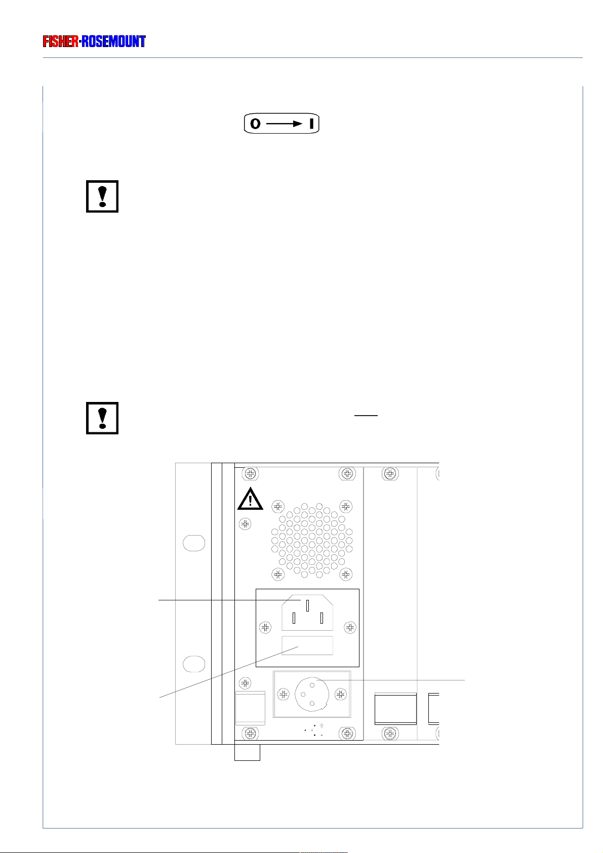
3. Supply Voltage
The socket outlet shall be installed near the equipment and shall be easily
accessible to disconnect the device from the socket outlet.
Verify whether the line voltage stated on the instrument (LFM 01) or power supply
agrees with that of your mains line!
Be sure to observe the safety precautions and warnings given by
manufacturer of pow er supply !
Rosemount Analytical
◆ NGA 2000 platform is a Safety Class 1 instrument
The platform is provided with a protective earth terminal.
T o prevent shoc k hazard, the instrument chassis and cabinet must be connected
to an electrical ground. The instrument must be connected to the AC pow er
supply mains through a three-conductor power cable, with the third wire firmly
connected to an electrical ground (safety ground) at the power outlet.
If the instrument is to be energized via an external power supply , that goes for the
power supply too .
Any interruption of the protective (grounding) conductor or disconnection of the
protective earth terminal will cause a potential shock hazard that could result in
personal injury. Deliberate disconnection is inadmissible / prohibited !
Verify that the position of input voltage switch of the 10 A power supply agrees
with that of your mains line (Fig. 20-3 and 1-4) !
Verify correct polarity for 24 V dc - operation !
S - 4
90002496(2) [NGA-Platform e] 30.03.99

Rosemount Analytical
4. Instrument specific notes for the user
The installation site for the instrument has to be dry and remain above freezing
point at all times.
The instrument must be exposed neither to direct sunlight nor to strong sources
of heat. Be sure to observe the permissible ambient temperature !
For outdoor sites, we recommend to install the instrument in a protective cabinet.
At least, the instrument has to be protected against rain (e.g., shelter).
Free flo w of air into and out of the platform (ventilation slits) must not be hindered
by nearby objects or w alls !
SAFETY SUMMARY
INSTRUMENT SPECIFIC NOTES FOR USER
Use only from our factory optional delivered cables or equiv alent shielded cables
to be in agreement with the CE - conformity.
The customer has to guarantee, that the shield is be connected bothsided.
Shield and connectors housing have to be connected conductiv e.
Sub.-min.-D-plugs/soc kets have to be scre w ed to the analyzer.
By using of optional delivering terminal strip adapters the analyzer is not be in
agreement with the CE - conformity . In this case CE - conf ormity is to be declared
by customer as “manufacturer of system”.
90002496(2) [NGA-Platform e] 30.03.99
S - 5
SAFETY SUMMARY
ADDITIONAL NOTES FOR SERVICE / MAINTENANCE
5. Additional notes for service / maintenance
Operating personnel must not remove instrument covers !
Component replacement and internal adjustments must be made by qualified
service personnel only !
Always disconnect power, discharge circuits and remove external voltage
sources before troub leshooting, repair or replacement of any component !
Any work inside the instrument without switching off the power must be
performed by a specialist, who is familiar with the related danger, only !
Rosemount Analytical
In case of exchanging fuses the customer has to be certain that fuses of specified
type and rated current are used. It is prohibited to use repaired fuses or def ective
fuse holders or to short-circuit fuse carriers (fire hazard).
At component replacement or installation the RF shielding contacts must not be
bended !
S - 6
90002496(2) [NGA-Platform e] 30.03.99

Rosemount Analytical
ELECTROSTATIC DISCHARGE
SAFETY SUMMARY
5.1 Electrostatic Discharge
The electronic parts of the analyzer can be irreparably damaged if exposed to electrostatic
discharge (ESD).
The instrument is ESD protected when the covers have been secured and safety precautions
observed. When the housing is open, the internal components are not ESD protected anymore.
Although the electronic parts are reasonable safe to handle, you should be a ware of the following
considerations:
Best ESD example is when you w alked across a carpet and then touched an electrical grounded
metal doorknob. The tiny spark which has jumped is the result of electrostatic discharge (ESD).
You prevent ESD by doing the following:
Remove the charge from your body before opening the housing and maintain during work with
opened housing, that no electrostatic charge can be built up.
Ideally you are opening the housing and working at an ESD - protecting workstation.
Here you can wear a wrist trap.
However, if you do not have such a workstation, be sure to do the following procedure exactly:
Discharge the electric charge from your body. Do this by touching a device that is grounded
electrically (any device that has a three - prong plug is grounded electrically when it is plugged into
a power receptacle).
This should be done several times during the operation with opened housing (especially after
leaving the service site because the movement on a low conducting floors or in the air might cause
additional ESDs).
90002496(2) [NGA-Platform e] 30.03.99
S - 7

SAFETY SUMMARY
Rosemount Analytical
S - 8
90002496(2) [NGA-Platform e] 30.03.99

Rosemount Analytical
INTRODUCTION
Introduction
This operation manual informs you about the platform, which is used for accommodating
analyzers or analysis modules of the NGA 2000 series (19", 3 HU, IP 20-housing).
Platform
This housing, together with the operator interface and the built-in controller board ACU 02,
represents the platform for analyzers of the NGA 2000 series.
EMC-Housing
Should the housing be used as an EMC-assembly carrier for non-EMC analysis modules, please
be aware that the installation differs from the description given in this manual. The following
changes must be taken into consideration:
1. The 19" operator interf ace (chapter 1.1) will be substituted by two 1/2 19" blind front panels .
Each blind front panel can be dismounted separately by remo ving the respective screws
(6 for each panel).
2. The controller board ACU 02 (chapter 1.3.4) will be replaced by a bulkhead plate.
3. Only rear-panel modules using network can be built-in in this housing.
Modules which need the ICB-bus can not be connected, because the A CU 02 board is not
installed.
4. The operation of built-in analyzer module and any additional rear-panel modules must be
carried out via a "true-type" platform or a superior analyzer.
90002496(2) [NGA-Platform e] xx.03.99
E - 1

INTRODUCTION
Rosemount Analytical
E - 2
90002496(2) [NGA-Platform e] xx.03.99

Rosemount Analytical
TECHNICAL DESCRIPTION
1. Technical Description
The basis for analyzers of the NGA 2000 series is a 19", 3 HU housing of IP 20 protection class.
The instrument can be delivered as table top or rac k mountable unit.
The platform contains all components necessary for operating the analyzer and can be used as
a "stand alone" analysis instrument when combined with an analyzer module and an Input/Output
(I/O) module, or it can be configured as a system when equipped with sev eral analyzer and I/O
modules.
The conceptional design is depicted in the block diagram below (Fig. 1-1).
90002496(2) [NGA-Platform e] 30.03.99
Fig. 1-1: Block diagram platform design (external)
1 - 1

TECHNICAL DESCRIPTION
Rosemount Analytical
NGA standard housing contains:
◆ the front panel (84 DU, see chapter 1.1)
◆ the interconnection board ICB 01 (see chapter 1.3.1)
◆ the line-fan module LFM 01 (12 DU, see chapter 1.3.3), the power supply (see chapter 1.3.2)
and the controller board ACU 02 (see chapter 1.3.4)
◆ the network module LEM 01 for connecting the platform with external analyzer modules
(see chapter 1.3.5)
◆ 5 free slots (PCBs, 5 DU) on the rear panel, which can be assigned optionally with
“Input / Output Modules” (I/O's)
e.g. programmable I/O's: one SIO and up to 4 DIO boards
◆ 4 internal free slots (Euro cards) which can be assigned optionally (for 5 A power supply only)
AC DC
Platform
Analyzer Module
Analyzer Module
Analyzer Module
1 - 2
Network Cable
Fig. 1-1a: Analyzer system via platform (schematic diagram)
Network Cable
24VDC Cable
Power supply
24VDC Cable
90002496(2) [NGA-Platform e] 30.03.99

Rosemount Analytical
TECHNICAL DESCRIPTION
FRONT PANEL
1.1 Front Panel
The 1/1-19" front panel (84 DU) accommodates the LCD display , accompanying front panel circuit
board AFP 01 and the keys necessary for operating the instrument (see Fig. 1-2).
For assembling and disassembling the analyz er module and for maintenance and repair, the front
panel can be swivelled out after releasing the six fastening screws, while the instrument may
remain in operation.
Footing
(table-top housing only)
Fastening screws
front panel
LCD display
F 3F 1 F 2 F 4 F 5
Softkeys
(Function depends on menu)
Cursor keys
NGA 2000
ENTER key
Mounting
(with rack mount-
able housing only)
90002496(2) [NGA-Platform e] 30.03.99
Fig. 1-2: Housing, Front View
(Front panel)
1 - 3

TECHNICAL DESCRIPTION
REAR PANEL
Rosemount Analytical
1.2 Rear Panel
The rear panel (84 DU) accommodates (see Fig. 1-3):
◆ the line-fan module LFM 01 (12 DU, see chapter 1.3.3)
◆ the network module LEM 01 for connecting the platform with external analyzer modules
(see chapter 1.3.5)
◆ 5 free slots (PCBs, 5 DU) on the rear panel, which can be assigned optionally with
“Input / Output Modules” (I/O's)
e.g. programmable I/O's: one SIO and up to 4 DIO boards
◆ the gas fittings and optional electrical connections of analyzer modules (see separately
operation manual)
Analyzer module
(optionally built-in)
Footing
Line - Fan - Module
LFM 01 (12 DU)
5 free slots for optional
rear-panel modules
(PCB's, 5 DU)
Network Module
LEM 01 (5 DU)
(table-top housing only)
Mounting (at the front)
(with rack mountable
housing only)
1 - 4
Fig. 1-3: Housing, Rear View
90002496(2) [NGA-Platform e] 30.03.99

Rosemount Analytical
TECHNICAL DESCRIPTION
INTERNAL LAYOUT
1.3 Internal Layout
The interior of the housing is divided into two 42 DU wide halves.
When looking from the front side, on the right there is the electronics with interconnection board
and printed circuit board (PCB of Euro standard format).
On the left side, there is spare room for locating an analyzer module.
Network Module
LEM 01 (5 DU)
Interconnection Board
ICB 01
Analysis module
(optionally built-in)
5 free slots for optional I/O's
(PCBs, 5 DU)
Line- Fan - Module
LFM 01 (12 DU)
5 A
Power Supply
(for MLT, TFID
analyzer modules)
Mounting
rack mountable housing
(option)
90002496(2) [NGA-Platform e] 30.03.99
4 optional internal PCBs
Retention pin of analysis module
(dependent on analysis module version)
Carrying handles
Fig. 1-4a: Internal view of housing (with 5 A power supply)
Controller Board
ACU 02
hinge
front panel
Front panel with LCD display
and AFP 01 - PCB
1 - 5

TECHNICAL DESCRIPTION
INTERNAL LAYOUT
Rosemount Analytical
Network Module
LEM 01 (5 DU)
Interconnection Board
ICB 01
Analyzer module
(optionally built-in)
5 free slots for optional I/O's
(PCBs, 5 DU)
Line- Fan - Module
LFM 01 (12 DU)
10 A
Power Supply
(for CLD, WCLD,
HFID, McFid
analyzer modules)
1 - 6
Controller Board ACU 02
Front panel with LCD display
Carrying handles
Fig. 1-4b: Internal view of housing (with 10 A power supply)
24 Vdc
to
analyzer module
Fan
hinge
front panel
and AFP 01 - PCB
90002496(2) [NGA-Platform e] 30.03.99
Rosemount Analytical
INTERCONNECTION BOARD ICB 01
TECHNICAL DESCRIPTION
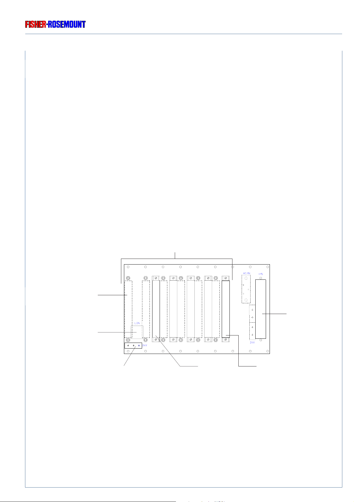
1.3.1 Interconnection Board ICB 01
The board ICB 01 (see Figs. 1-4 and 1-5) interconnects the line-fan module (LFM 01), the power
supply (PSM) and all inserted PCBs [Euro cards with parallel ICB-bus system] and built-in analysis
module (RJ 45 network interface).
PCBs and the required voltage supply can be connected to the ICB with the so-called ICB-bus
[(a 64-pin plug-in connection DIN 41612 C 64) see Fig. 1-7].
ICB ensures the internal network connection which is necessary for operating the analyzer /
analyzer module.
With 5 A power supply it supplies the analyzer module with 24 Vdc required.
Slots for PCBs
with 64-pin ICB-Bus
(double-sided)
Slot for network module
LEM 01
(Rear side)
internal network - connection
to analyzer module
(RJ 45 socket)
Slot for
24 Vdc to
analyzer module
(with 5 A power supply)
Slot for
Controller board ACU 02
(with 10 A power supply)
Controller board ACU 02
(with 5 A power supply)
Slot for
power supply
90002496(2) [NGA-Platform e] 30.03.99
Fig. 1-5: Printed Circuit Board ICB 01
(viewed from front panel)
1 - 7
TECHNICAL DESCRIPTION
INTERCONNECTION BOARD ICB 01
Rosemount Analytical
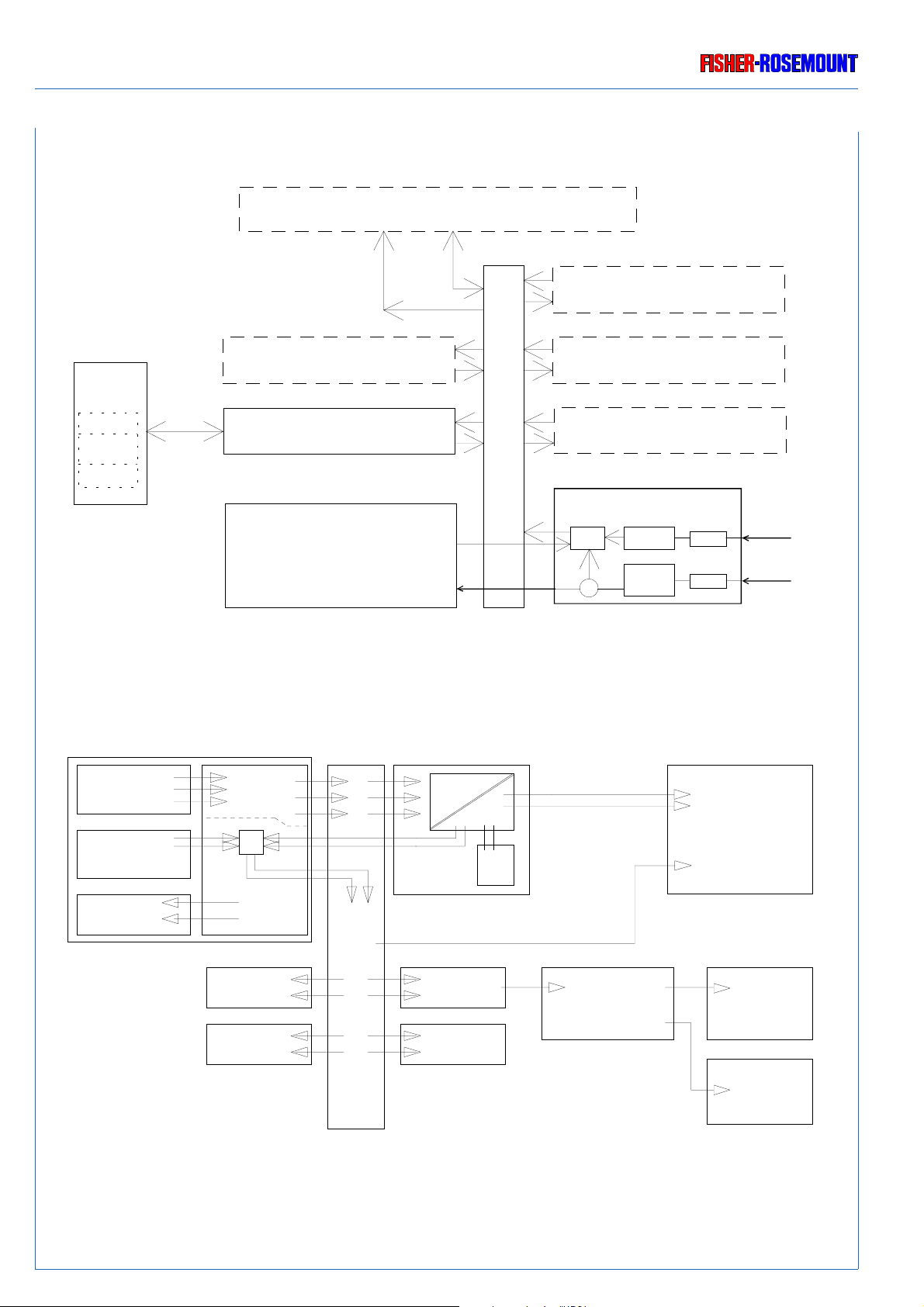
Analyzer Module (AM)
Platform
Front pan el
Keys
AFP - PCB
LCD - Dusplay
Optional PCBs (4 x)
Control Unit ACU 01
(Power Su pply)
24 Vdc / 5 A
24 V dc
24 Vdc
Autorange
230 / 115 Vac
Nertwork
ICB 01
Inter-Connection-Board
Network - Module
Optional Inputs/Outpu ts (4 x)
Standard Inp uts/Outputs
SIO
Line-Fan-Module
LFM 01
Logic
Filter
Main-
filter
Fig. 1-6a: Block diagram internal platform design (with 5 A power supply)
Fuse
Fuse
24 Vdc
Mains
EMI fil te r
LFM 01
ext. 24 Vdc in
Fan
L1, N, PE
or
24 Vdc
L1, N, PE
24 Vdc
230/115 V ac
Power Supply
24 Vdc out
Fan
NEB 01
Network
PCB
PCB
24 Vdc
24 Vdc
ACU AFP
PCB
ICB 01
Fig. 1-6b: Block diagram internal platform design (with 10 A power supply)
24 Vdc
Analyzer Module
Network
LCD
Keyboard
1 - 8
90002496(2) [NGA-Platform e] 30.03.99
Rosemount Analytical
TECHNICAL DESCRIPTION
INTERCONNECTION BOARD ICB 01 / POWER SUPLLY UNIT
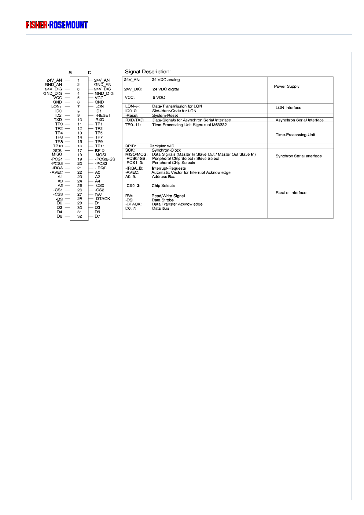
Fig. 1-7: Pin assignment, 64-pin ICB-bus connector
1.3.2 Power Supply Unit
The power supply unit converts the voltage supply from 230 / 115 Vac to 24 Vdc required for
operating the instrument.
Alternatively two different power supplys can be built in (see Fig. 1-4a and 1-4b too):
One power supply can be loaded with up to 5 A and is provided with autoranging between 230
Vac and 115 Vac (rear panel of LFM 01 shows “230/115 VAC”).
The other power supply can be loaded with up to 10 A and is provided with a manual switch
between 230 Vac and 115 V ac (rear panel of LFM 01 sho ws “230 V A C” or “115 V A C”). To prevent
excessively high temper ature inside the housing, a fan is installed inside (see Figs. 1-4b). The air
enters through openings in the front of the side walls.
The necessary connection of line-fan module (see 1.4) is provided by the ICB 01 board via a
matching plug (DIN 41612 / H 15).
The slot is located in front on the outer right side of ICB 01 (when looking from the front panel),
see Figs. 1-5 and 1-4.
To exchange 5 A power supply (standard) to 10 A power supply via retrofit kit, contact service
support center please.
90002496(2) [NGA-Platform e] 30.03.99
1 - 9

TECHNICAL DESCRIPTION
Rosemount Analytical
LINE-FAN MODULE (LFM 01)
1.3.3 Line - Fan - Module (LFM 01)
The NGA basic design has been provided for an operating v oltage of 230 V ac (196 - 264 V ac), 47
- 63 Hz and 115 Vac (93 - 132 Vac) resp., 47 - 63 Hz and / or 24 Vdc ( ± 10 %).
The line-fan-module (LFM 01) connects the NGA unit to the AC mains line or to a 24 Vdc low
voltage supply.
The unit (12 DU) is put in the housing from the rear side (see Figs. 1-8, 1-3 and 1-4).
AC - connector
(230 / 115 Vac;
50 / 60 Hz)
Fuses AC
(F1/F2: T 3,5 A)
POWER
230 V
115 V
50/60 Hz
F1/F2
T3,5A / 230V
~
~
LFM 01
-DC 24 V IN -
Fan
24 Vdc - connector
1
3
2
1 - 10
Fig. 1-8: Rear panel LFM 01 (sectional view of the housing)
90002496(2) [NGA-Platform e] 30.03.99

Rosemount Analytical
TECHNICAL DESCRIPTION
LINE-FAN MODULE (LFM 01)
AC - voltage cable is connected via an IEC power lead. Power failure (RF noise) or internal
interference is suppressed by an RF filter with two integrated fuses (5 x 20 mm).
If rear panel of LFM 01 shows “230/115 VAC”, there is built-in the 5 A power supply
with autoranging of input AC voltage.
If rear panel of LFM 01 shows “230 VAC” or “115 VAC”, there is built-in the 10 A
power supply with manual switch of input AC voltage..
Verify beforehand that the line voltage stated on the LFM 01
agrees with that of your power supply line !
Verify that the position of input voltage switch of the 10 A power supply agrees
with that of your power supply line (Fig. 20-3 and 1-4) !
The 24 Vdc voltage is connected via a 3-pin socket (XLR), whereby filtered DC voltage has to be
available. The remaining interferences will be prevented by internal filters.
Verify correct polarity for 24 V dc - operation !
The instrument is protected against reversed polarity.
If both 24 Vdc and 230/115 Vac voltage are supplied simultaneously, the AC voltage will be
preferred. The 24 Vdc then is automatically disconnected by a relay. The 24 Vdc will be used only
while cessation of the AC voltage.
Ventilation
To prevent excessively high temperature inside the housing, a ventilator is installed on the rear side
of the LFM 01 (see Figs. 1-8 and 1-3).
The ventilator sucks air from the housing.
The air enters through openings in the front of the side walls.
90002496(2) [NGA-Platform e] 30.03.99
1 - 11

TECHNICAL DESCRIPTION
CONTROLLER BOARD ACU 02
Rosemount Analytical
1.3.4 Controller Board ACU 02
The ACU 02 controller board is the “heart” of the NGA platform. It is a one board CPU card. When
the voltage supply is disconnected, all user data will be safe loaded via a battery buffer.
This board functions as a networks manager, allows the access to each built-in component, and
controls the analyzer modules, the LCD display, and the operation procedures.
The slot for ACU 02 is located on the ICB 01 (when viewed from the front panel) on the right side
of the 64-pin ICB bus with internal5 A power supply and on the left side with internal 10 A power
supply (left from power supplys), see Figs. 1-5 and 1-4.
The board contains the following function blocks:
◆ 32 / 16-bit micro controller
◆ Floating point co-processor
◆ dependent on platform version different RAM / Flash-EEPROM
(Standard: 1 MB RAM extension for up to 15 software channels*); Option: additional 0.5 MB RAM extension
if more than 15 software channels*);contact factory if more than 20 software channels are requested)
◆ Real-time Clock with
Calendar function
Alarm function
◆ Watchdog function
◆ Serial interface RS 232 C
◆ A network interface with ECHELON chip
◆ System bus:
Parallel bus A6 : D8
12 TPU wiring
network bus
Synchron serial bus
◆ Buffered parallel interface for LCD control
◆ Local bus interface (e.g. storage extension)
◆ Switch-mode power supply for 5 V supply (on board)
*) Calculate software channels (SW) as follows: MLT = 1 SW ch. for each measuring channel; all other NGA analyzer modules like
CLD, FID, etc. = 1 SW ch.; SIO/DIO = zero SW ch.; network I/O's = 1/2 SW ch.
1 - 12
90002496(2) [NGA-Platform e] 30.03.99

Rosemount Analytical
TECHNICAL DESCRIPTION
NETWORK MODULE LEM 01
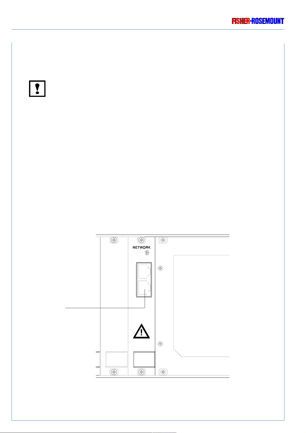
1.3.5 Network Module LEM 01
The network module LEM 01 (see Fig. 1-9) connects the platf orm (controller board) with external
modules via network. The slot on the interconnection board is located on the outer right (vie wed
from the rear side), left from the optionally built-in analyzer module.
Note !
The external modules cannot be supplied with 24 Vdc from the platform and, therefore, hav e to
be externally powered (see Fig. 1-1a, too).
NET
1
NET
2
Network - twin - connector
to external modules
(two RJ 45-sockets)
Analyzer module
(optionally built-in)
Fig. 1-9: Rear panel network module LEM 01 (sectional view of the housing)
RJ 45 sockets are serving for network interconnection.
It is necessary to terminate the ends of a twisted pair bus to minimize reflections (see Fig. 1-11).
Failure to terminate the bus will degrade network performance.
Termination will be done via RJ 45 connectors (see Fig. 1-10).
Fig. 1-10: RJ 45 network termination connector
90002496(2) [NGA-Platform e] 30.03.99
1 - 13

TECHNICAL DESCRIPTION
NETWORK MODULE LEM 01
Rosemount Analytical
Termination
AM AM AM AM
Platform
Termination
AM AM AM AM AM
Termination
AM AM
Termination
AM
Platform
AM
Platform
Termination
AM
Termination
AM AM
Platform
Fig. 1-11: Network termination (examples)
1 - 14
90002496(2) [NGA-Platform e] 30.03.99

Rosemount Analytical
PREPARATION
INSTALLATION SITE
5. Preparation
Please check the packing and its contents immediately upon arrival.
If any damage is observed or items are missing, then we request that you notify the forw arder to
undertake a damage surve y and report the loss or damage to us immediately.
5.1 Installation Site
Be sure to observe the additional notes, safety precautions and wa rnings given
in the individual manuals (platform, modules, I/O boards etc.) !
The platform must not operate in explosiv e atmosphere without supplementary
protective measures !
Free flo w of air into and out of the platfrom (ventilation slits) must not be hindered
by nearby objects or w alls !
The installation site for the Platform has to be dry and remain above freezing point
at all times. The platform must be e xposed neither to direct sunlight nor to strong
sources of heat.
Be sure to observe the permissible ambient temperatures (c.f. Item 20: T echnical
Data). For outdoor installation, we recommend to install the platform in a
protective cabinet. At least, the platorm has to be protected against rain (e.g.,
shelter).
90002496(2) [NGA-Platform e] 30.03.99
5 - 1
PREPARATION
EXTERNAL MODULES
Rosemount Analytical
5.2 External Modules
Observe the safety precautions and warnings for the modules !
Consider also the procedure steps with regard to handling, configuration,
and operation if given in the individual manual(s) !
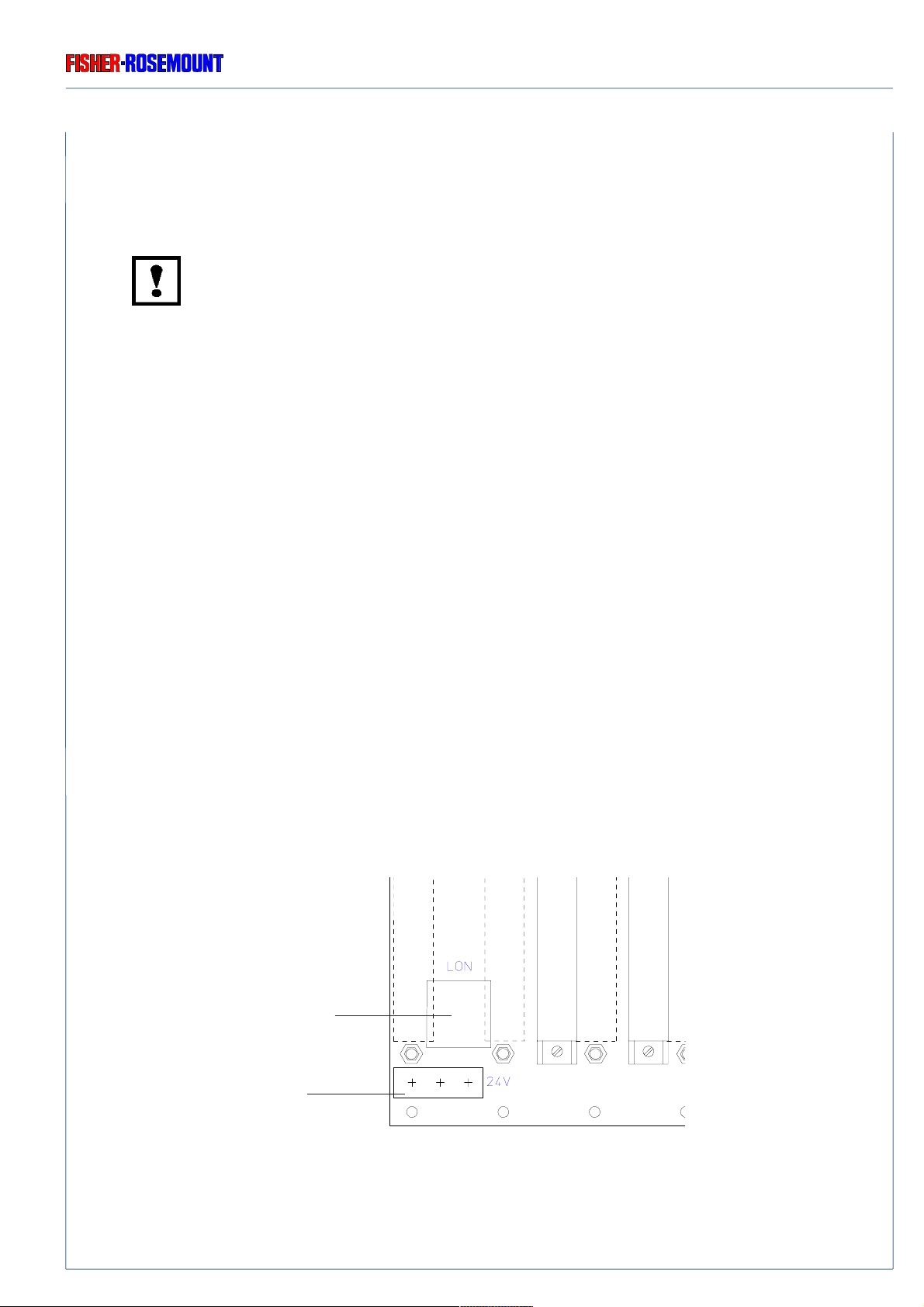
The platform (controller board) can be connected with external analyzer modules via the network
module LEM 01 (see Fig. 5-1). RJ 45 sockets are serving for network interconnection. Be sure
to observe the network termination (see section 1.3.5).
Note !
The external modules cannot be supplied with 24 Vdc from the platform and, therefore, have to
be externally powered (see Fig. 1-1a).
NET
1
NET
2
network - twin - connector
to external modules
(two RJ 45-sockets)
Analyzer module
(optionally built-in)
5 - 2
Fig. 5-1: Rear panel network module LEM 01 (sectional view of the housing)
90002496(2) [NGA-Platform e] 30.03.99
Rosemount Analytical
INSTALLATION OF AN ANALYZER MODULE
PREPARATION
5.3 Installation of an Analyzer Module into the Platform
Be shure to observe the safety precautions and warnings !
Installation must be made by qualified service personnel only !
Consider also the procedure steps with regard to handling, configuration,
and operation if given in the individual manual(s) !
For the installation of analyzer module into the platform consider the following steps:
❍ Loosen the six fastening screws for the front panel (Fig. 1-2), hold the handles, and s wing
the front panel to the farest right (see also section 15.1).
❍ Lift the retention pin(s), push the analyzer module in the left half of the housing until the
retension pin(s) lock(s) into the pin seats in the lower analyz er module guides.
❍ Connect the required network wiring between the analyzer module (see the individual
operation manual) and the interconnection board ICB 01 (Fig. 5-2 and 1-5).
❍ Connect the required 24 Vdc wiring between the analyzer module (see the individual
operation manual) and the interconnection board ICB 01 (platform with 5 A power supply,
Fig. 5-2 and 1-5) or the PCB of po wer supply (platform with 10 A power supply, Fig. 1-4b)
resp..
❍ Close the instrument (i.e., re-attach the front panel, see section 15.1).
internal network - connection
to analyzer module
(RJ 45 socket)
24 V DC to
internal analyzer mod-
ule
90002496(2) [NGA-Platform e] 30.03.99
Fig. 5-2: Printed Circuit Board ICB 01
(viewed from front panel)
5 - 3
PREPARATION
INSTALLATION OF PCBS / REAR MOUNTING MODULES
5.4 Installation of PCBs / Rear Mounting Modules
Insert or remove PCBs when the instrument is electrically disconnected only !
Be shure to observe the safety precautions and warnings !
Installation must be made by qualified service personnel only !
Consider also the procedure steps with regard to handling, configuration,
and operation if given in the individual manual(s) !
5.4.1 Rear Mounting Modules
Rosemount Analytical
Follow the procedure steps to insert cards:
❍ Unscrew the shielding blind-plate of the chosen slot and remove it.
❍ Put the backplane module in the chosen slot, and fasten the back panel with screws.
5.4.2 Internal Slots (with 5 A power supply only)
Follow the procedure steps to insert cards:
❍ Loosen the six fastening scre ws of the front panel (Fig. 1-2) and s wing the front panel to the
farest left (see also section 15.1).
❍ Tilt the card ejector upwards and push the card in the chosen slot until the card catch locks
into place.
❍ Close the instrument (i.e., re-attach the front panel, see section 15.1).
5 - 4
90002496(2) [NGA-Platform e] 30.03.99
Rosemount Analytical
SWITCHING ON
6. Switching On
Be shure to observe the safety precautions and warnings !
Observe the additional notes, safety precautions and warnings given in the
individual manuals (modules, I/O boards) !
Once the instrument has been correctly assembled and installed in accordance with the general
instructions given in section 5., the equipment is ready for operation.
The instrument is switched on by providing the required v oltage.
The instrument is specified for an operating voltage of 230 V A C (196 - 264 V A C), 47 - 63 Hz or
115 V AC (93 - 132 V AC) resp., 47 - 63 Hz and / or 24 V DC (± 10 %).
The platform must be switched on only after s witching on all modules connected
to the network. Be sure to observe the network termination (see section 1.3.5)!
LFM 01
POWER
~
230 V
~
115 V
50/60 Hz
AC - connector
(230 / 115 Vac;
50 / 60 Hz)
AC Fuses
F1/F2: T 3,5 A)
90002496(2) [NGA-Platform e] 30.03.99
F1/F2
T3,5A / 230V
-DC 24 V IN -
1
3
2
Fig. 6-1: Voltage Supply of NGA 2000 - Platform
24 Vdc - connector
6 - 1
SWITCHING ON
Rosemount Analytical
6.1 24 Vdc - Operation
The 24 Vdc v oltage is connected via a 3-pin socket (XLR), whereb y filtered DC voltage has to be
available. The remaining interferences will be prevented by internal filters.
When both 24 Vdc and V ac voltage are supplied simultaneously , the A C voltage will be preferred.
The 24 Vdc then is automatically disconnected by a relay. The 24 Vdc will be used only while
cessation of the AC voltage .
❍ Connect power supply and Line-Fan-Module (LFM 01), (see Fig. 5-1, DC - connector).
V erify whether the line voltage stated on the instrument or power supply agrees
with that of your mains line!
Verify correct polarity for 24 V dc - operation !
Be sure to observe the safety precautions and warnings given by
manufacturer of power supply !
❍ Connect mains line and power supply.
6.2 230 / 115 Vac - Operation
❍ Connect mains line and Line-Fan Module (LFM 01), (see Fig. 5-1, AC - connector).
Verify beforehand that the line voltage stated on the LFM 01
agrees with that of your mains line !
Verify that the position of input voltage switch of the 10 A power supply ag rees
with that of your mains line (Fig. 20-3 and 1-4) !
If rear panel of LFM 01 shows “230/115 VAC”, there is built-in the 5 A power supply
with autoranging of input AC v oltage.
If rear panel of LFM 01 shows “230 VAC” or “115 VAC”, there is built-in the 10 A
power supply with manual switch of input AC voltage..
Upon switching on, the analyzer will perform a self-diagnostic test routine.
After switching on the analyzer , the software intergr ates automatically all the individual modules,
which are incorporated in the analyzer via network and have been previously s witched on, in the
system.
For former inf ormations to the displays while s witching on look at the respective software manual.
6 - 2
90002496(2) [NGA-Platform e] 30.03.99

Rosemount Analytical
7. Switching Off
The platform is switched off by disconnecting the voltage supply.
Be shure to observe the safety precautions and warnings !
Consider also the procedure steps with regard to handling, configuration,
and operation if given in the individual manual for analysis module(s)
and additional PCBs !
SWITCHING OFF
90002496(2) [NGA-Platform e] 30.03.99
7 - 1

SWITCHING OFF
Rosemount Analytical
7 - 2
90002496(2) [NGA-Platform e] 30.03.99
Rosemount Analytical
11. Troubleshooting
The instrument cover can be removed when necessary (see 15.).
Be sure to observe the safety precautions and warnings !
Trouble-shooting, component replacement and internal adjustments must be
made by qualified service personnel only !
TROUBLESHOOTING
NO FUNCTION (LCD DISPLAY)
11.1 Instrument has no Function (LCD display is dark)
Possible Causes Check / Correct
a) External supply voltage is absent: Check electrical supply
- DC polarity is reversed Check electrical supply
b) Possible error at line-fan module: LFM 01 is not correctly connected,
for further causes see 11.3
c) Possible error at internal power supply: Causes see 11.4
d) Internal connections incorrect or absent: Chec k internal connections:
Check whether ACU 02 is in correct place
Check ACU 02 - AFP 01 connection cable
e) AFP 01 board or LCD display defective Exchange front panel (see 17.3)
g) EPROM / A CU 02 defective: Replace EPROM / ACU 02
(see 17.4 and 17.2)
90002496(2) [NGA-Platform e] 30.03.99
11 - 1
TROUBLESHOOTING
NO MEASUREMENT SCREEN
Rosemount Analytical
11.2 No Measurement Screen
Possible Causes Check / Correct
Internal analyzer module
a) Internal connection incorrect: Check internal connection (24 Vdc/Network)
between ICB and analyzer module, and
replace cable if necessary.
b) Defective analyzer module: See the operating and servicing manual of
the analyzer module.
External modules
a) Switched off module: Switch on the module
b) No external power: Check external power supply
c) Defective network connection: Check network termination (see section 1.3.5).
Check network connection between platform
and external module, or replace the
connection cable or network module (platform)
if necessary.
d) Analyzer module has not been integrated Integrate the analyzer module in the
in the system software (network): system software (see software manual).
e) Defective analyzer module: See the operation manual of the analyzer
module.
11 - 2
90002496(2) [NGA-Platform e] 30.03.99
Rosemount Analytical
11.3 Line - Fan - Module (LFM 01)
Possible Causes Check / Correct
a) Fan does not function: For DC operation:
TROUBLESHOOTING
LINE - FAN - MODULE / POWER SUPPLY UNIT
Pull out LFM, check fuse F 3 and replace
if necessary (see section 11.5).
In case the fuse function is properly:
LFM 01 defective, exchange module
For AC oper ation: see section 11.3 b)
b) For AC operation: Fuses defective Check fuses F 1 and F 2 and replace
if necessary (see section 11.5).
In case the fuses function is properly:
LFM 01 defective, exchange module
11.4 Power Supply Unit
Possible Causes Check / Correct
a) External supply voltage is absent: Check electrical supply
b) Green LED does not lighten: Instrument is DC operated
- Possible error at line-fan module: LFM 01 is not correctly connected,
for further causes see 11.3
- Power supply is not correctly connected Open the housing (see section 15.)
- Power supply is defective Exchange the module (see 17.2.2)
90002496(2) [NGA-Platform e] 30.03.99
and check correct fit
11 - 3

TROUBLESHOOTING
FUSES
11.5 Fuses
Be sure to observe the safety precautions and warnings !
Always disconnect power, discharge circuits and remov e external voltage before
checking the fuses !
In case of exchanging fuses the customer has to be certain that fuses of specified
type and rated current are used. It is prohibited to use repaired fuses or def ective
fuse holders or to short-circuit fuse carriers (fire hazard).
After visual checking, check the fuses with an ohmmeter.
Rosemount Analytical
If low impedance has been measured, the fuse is in order .
High impedance means, the fuse is out of order and must be replaced.
11.5.1 AC - Fuses
❍ Hinge down the fuse cov er of the AC socket (see Fig. 11-1).
❍ T ake out and check the fuses . Replace the fuse(s) if necessary [T 3.5 A / 250 V (5 x 20 mm)].
❍ Reclose the cover.
11.5.2 DC - Fuses
❍ Loosen the four f astening screws for the LFM 01 (see Fig. 11-1) and take out the LFM 01.
❍ unscrew the fuse located on the left rear side of the LFM (see Fig. 11-2), and check the fuse.
Replace the fuse if necessary [T 6.25 A / 250 V (5 x 20 mm)].
❍ Reinsert and secure the LFM with the four screws.
11 - 4
90002496(2) [NGA-Platform e] 30.03.99

Rosemount Analytical
AC - connector
Fastening Screws
POWER
~
230 V
~
115 V
50/60 Hz
TROUBLESHOOTING
FUSES
LFM 01
AC - Fuses
F1/F2:
T 3,5 A / 230 V
F1/F2
T3,5A / 230V
-DC 24 V IN-
1
3
2
Fig. 11-1: AC - Fuses of LFM 01
fuse cover
24 Vdc - connector
90002496(2) [NGA-Platform e] 30.03.99
DC - Fuse
F3: T 6,25 A / 250 V
Fig. 11-2: DC - Fuse of LFM 01
11 - 5

TROUBLESHOOTING
Rosemount Analytical
11 - 6
90002496(2) [NGA-Platform e] 30.03.99

Rosemount Analytical
15. Opening the Housing
Open the housing in case of troubleshooting, repair and service.
Be sure to observe the safety precautions and warnings !
Trouble-shooting, component replacement and internal adjustments must be
made by qualified service personnel only !
OPENING THE HOUSING
15.1 Front Panel
Use the following steps to remo ve the front panel:
❍ Loosen the six fastening screws of the front panel (Fig. 1-2.).
❍ Swing the front panel outwards.
Due to the built-in hinge mechanism, it is possible to swing the front panel at a certain
angle.
Thus, the inserted PCBs or the analysis module are rendered accessible.
The instrument can be operated even with opened front panel which is advantageous
during servicing.
❏ Reassembling is carried out in reverse sequence .
90002496(2) [NGA-Platform e] 30.03.99
15 - 1

OPENING THE HOUSING
15.2 Housing Cover
If required, the cover can be removed.
❍ Loosen the eight lateral recessed head screws on top .
❍ Pull the cover straight up.
❏ Reassembling is carried out in reverse sequence .
Rosemount Analytical
The cellular plastic insulation sticked on the bottom side of the co ver must
always be placed above the power supply unit !
15 - 2
90002496(2) [NGA-Platform e] 30.03.99

Rosemount Analytical
17. Removal / Replacement of Components
Exchange components if requested by repair or servicing
Be sure to observe the safety precautions and warnings !
Component replacement and internal adjustments must be made by qualified
service personnel only !
Consider also the procedure steps with regard to handling, configuration,
and operation if given in the individual manual(s) !
REMOVAL / REPLACEMENT OF COMPONENTS
REMOVAL OF ANALYSIS MODULE
17.1 Removal of Analyzer Module
Use the following steps to remove the analyzer module:
❍ Disconnect power.
❍ Loosen the six fastening screws of the front panel (Fig. 1-2) and s wing the front panel to the
farest right (see also section 15.1).
❍ Loosen the gas connections if necessary.
To avoid a danger to the operators by e xplosive, toxic or unhealthy gas
components, first purge the gas lines with ambient air or nitrogen (N2) before
cleaning or exchange parts of the gas paths.
In case it is necessary to open the gas paths, close the analyzers
gas connections with PVC caps immediatly !
❍ Disconnect analyzer module wiring (24 Vdc and network) if necessary (see section 5.).
❍ Unlock the retention pin(s) (Fig. 1-4a) and pull out the analysis module carefully.
❏ For installation see section 5.2.
90002496(2) [NGA-Platform e] 30.03.99
17 - 1
REMOVAL / REPLACEMENT OF COMPONENTS
REMOVAL / REPLACEMENT OF PCBS / REAR MOUNTING MODULES
17.2 Removal / Replacement of PCBs / Rear Mounting Modules
Always disconnect power, discharge circuits and remove external voltage
sources before troub leshooting, repair or replacement of any component !
Be sure to observe the safety precautions and warnings !
Component replacement and internal adjustments must be made by qualified
service personnel only !
17.2.1 Rear Mounting Modules
Rosemount Analytical
❍ Loosen fastening screws of the module of interest, press do wn the le ver to unloc k module
and remove module.
❍ Replace the module und fasten the screws .
17.2.2 Internal Slots
❍ Loosen the six fastening screws of the front panel (Fig. 1-2) and s wing the front panel to the
farest left (see also section 15.1).
PCBs:
❍ Push the card ejector downwards to unlock the card of intereset and remove the card.
❍ Tilt the card ejector of the new card upwards and put in the card until the catch locks
into place.
Power Supply Unit:
❍ Push the catch downwards and remove the power supply unit by pulling at its handel
(Fig. 1-4) .
❍ Put in the new unit until the catch locks into place .
❍ Close the instrument (i.e., re-attach the front panel, see section 15.1).
17 - 2
90002496(2) [NGA-Platform e] 30.03.99
Rosemount Analytical
REMOVAL / REPLACEMENT OF COMPONENTS
REMOVAL / REPLACEMENT OF FRONT PANEL
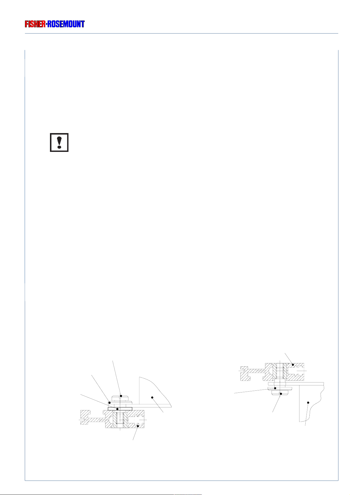
17.3 Removal / Replacement of Front Panel
Front panel plate together with LCD display, circuit board AFP 01, and hinge mechanism
constitutes an unit. Therefore, the front panel has to be disassembled completely when one
component of the unit is out of order.
Be sure to observe the safety precautions and warnings !
Component replacement and internal adjustments must be made by qualified
service personnel only !
❍ Loosen the six fastening screws for the front panel (Fig. 1-2) and swing the front panel
outwards preferably to the right position (see also section 15.1).
❍ Remove the cab le (ACU 02 - AFP 01 connection) from the circuit board ACU 02.
❍ Unscrew both fastening screws (top and bottom screw) by using a short screwdriver
for the hinge mechanism to complete remove the front panel.
❍ Re-insert swivel mechanism and complete front panel in the housing and tighten both
fastening scre ws (top and bottom screws) by using a short screwdriver (see Fig. 17-1).
❍ Re-attach the cable (ACU 02 - AFP 01 connection) to the circuit board ACU 02.
❍ Close the instrument (i.e., re-attach the front panel, see section 15.1).
upper housing strut
lower fastening screw
metal washer
NYLON washer
Fig. 17-1: Fastening screws for the hinge mechanism (partial view)
90002496(2) [NGA-Platform e] 30.03.99
lower housing strut
hinge
mechanism
metal washer
upper fastening screw
hinge
mechanism
17 - 3
REMOVAL / REPLACEMENT OF COMPONENTS
REPLACEMENT OF EPROM / BUFFER BATTERY OF ACU 02
Rosemount Analytical
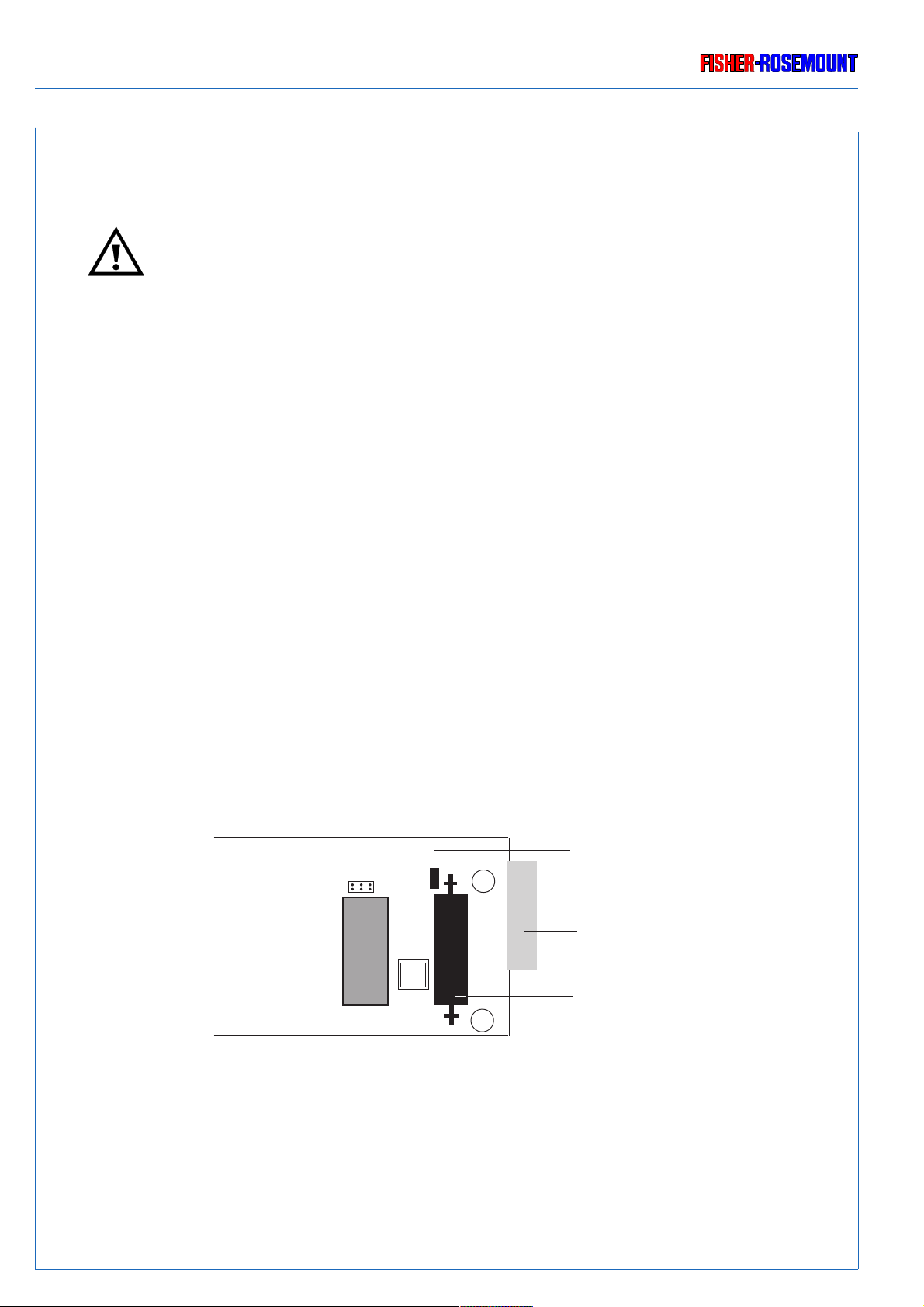
17.4 Replacement of EPROM / Buffer Battery on the ACU 02
Always disconnect power, discharge circuits and remove external voltage
sources before troub leshooting, repair or replacement of any component !
17.4.1 Removal of ACU 02
Use the following steps to remo ve the ACU 02 board:
❍ Loosen the six fastening screws of the front panel (Fig. 1-2) and s wing the front panel to the
farest left (see also section 15.1).
❍ Remove the cab le (ACU 02 - AFP 01 connection) from the circuit board ACU 02.
❍ Push the card ejector for the A CU 02 downwards and remove the board.
Battery Jumper (P 23)
(P20)
(P23)
+
Connection
to LCD dispaly
17 - 4
D32
EPROM
(P1)
-
Fig. 17-2: Controller Board ACU 02 (partial view, component side)
Buffer battery
on soldering pins
90002496(2) [NGA-Platform e] 30.03.99
Rosemount Analytical
REPLACEMENT OF EPROM / BUFFER BATTERY OF ACU 02
REMOVAL / REPLACEMENT OF COMPONENTS
17.4.2 Replacement of EPROM
The EPROM located on the ACU 02 ma y easily be replaced (e.g. in case of a def ective board or
a new program version). Use the following procedure to replace the EPROM:
❍ Remove the ACU 02 (see 17.4.1).
❍ Remove the jumper “P 23” for battery buffer (Fig. 17-2).
All data and compensation values entered by the user will be deleted (RAM-fail) !
❍ Remove the EPR OM from its socket (see Fig. 17-2).
❍ Insert the new EPROM.
Verify polarity when inserting the new EPROM !
A semicircular notch can be found both on the EPR OM and the socket.
○○○○○
○○○○○
For the correct insertion of the EPROM, both notches hav e to be superimposed.
After the replacement:
❍ Re-insert the jumper for battery buffer (Fig. 17-2).
❍ Install the ACU 02 (see 17.4.4).
90002496(2) [NGA-Platform e] 30.03.99
17 - 5
REMOVAL / REPLACEMENT OF COMPONENTS
REPLACEMENT OF EPROM / BUFFER BATTERY OF ACU 02
17.4.3 Replacement of Buffer Battery
Use the following procedure to replace the battery:
❍ Remove the ACU 02 (see 17.4.1).
❍ Remove the jumper “P 23” for battery buffer (Fig. 17-2).
All data and compensation values entered by the user will be deleted (RAM-fail) !
Rosemount Analytical
❍ Unsolder the battery from the soldering pins (see Fig. 17-2).
❍ Solder the new battery (Ordering No. 03 765 180) to the soldering pins (see Fig. 17-2).
Verify polarity when soldering the new battery (Fig. 17-2) !
After the replacement:
❍ Re-insert the jumper for battery buffer (Fig. 17-2).
❍ Install the ACU 02 (see 17.4.4).
17.4.4 Installation of ACU 02
❍ Tilt the card ejector of the ACU 02 upwards and put in the card until the catch loc ks into
place.
❍ Re-attach the cable (A CU 02 - AFP 01 connection) to the circuit board ACU 02.
❍ Close the instrument (i.e., re-attach the front panel, see section 15.1).
❍ Switch on instrument.
Now all the data required by the user can be entered again, e .g. system parameters.
17 - 6
90002496(2) [NGA-Platform e] 30.03.99

Rosemount Analytical
CLEANING OF HOUSING OUTSIDE
19. Cleaning of Housing Outside
For cleaning housing outside, you need a soft, fluff free cloth and all purpose detergent.
❍ Disconnect all voltage supplies.
To avoid a danger to the operators by e xplosive, toxic or unhealthy gas
components, first purge the gas lines with ambient air or nitrogen (N2) before
cleaning or exchange parts of the gas paths.
If it is necessary to disconnect the gas connections of analysis modules, the gas
line fittings of the module have to be closed with PVC-caps before cleaning !
❍ Moisten of the soft, fluff free cloth with the cleaning solution
(mixture of 3 parts water, 1 part all purpose detergent max.).
Be sure to use a moisted, but not wet, cloth only !
Be sure, that non liquid can drop into the housing inside !
❍ Cleaning of the platform housing outside with the moisted cloth.
❍ If required, rub off the housing with a dry cloth afterwards.
90002496(2) [NGA-Platform e] 30.03.99
19 - 1

CLEANING OF HOUSING OUTSIDE
Rosemount Analytical
19 - 2
90002496(2) [NGA-Platform e] 30.03.99
Rosemount Analytical
20. Technical Data
20.1 Platform
20.1.1 Housing
TECHNICAL DATA
PLATFORM
Certifications
1)
EN 50081-1, EN 50082-2, EN 61010-1
NAMUR, CSA NRTL/C, C-Tick, PAC, IS,
GOSSTANDART
Weight approx. 10 kg (including all standard modules)
Type of housing 19" - 3 HU, rack or table top housing
Materials Aluminum
Protection Class IP 20 (according to DIN standard 40050)
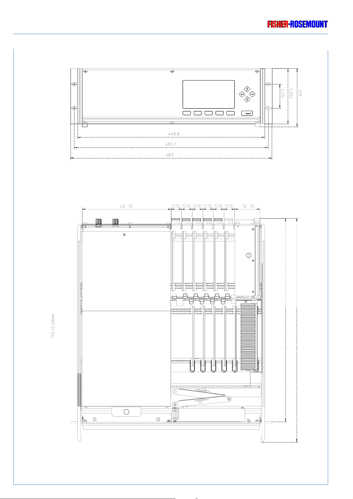
Dimensions see Figs. 20-1 and 20-2
20.1.2 Environments
Permissible ambient temperature + 5 °C to + 45 °C
Solar radiation (sunshine) The housing must not directly be irradiated by
sun light or fluorescence lamps.
Altitude 0 - 1500 m (above sea level)
Humidity (not- condensing) < 90 % rel. humidity at + 20 °C
< 50 % rel. humidity at + 40 °C
Rain / Drop- and splash water The housing must not be exposed to rain or
drop-/splash water.
Explosive atmosphere The housing must not be operated in explosive
atmosphere
1)
partly in preparation
90002496(2) [NGA-Platform e] 30.03.99
20 - 1
TECHNICAL DATA
PLATFORM
Rosemount Analytical
20 - 2
Fig. 20-1: Housing dimensions (in [mm]) (with standard analyzer module)
90002496(2) [NGA-Platform e] 30.03.99
488
537
Rosemount Analytical
TECHNICAL DATA
PLATFORM
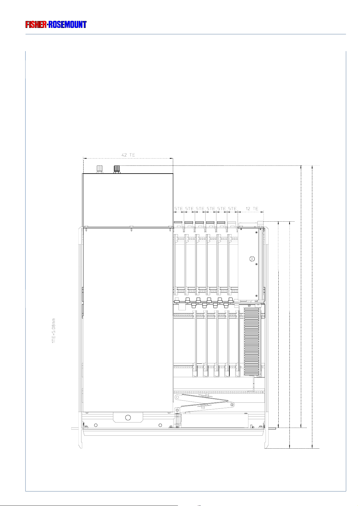
Fig. 20-2: Housing dimensions (in [mm]) (with extended analyzer module)
90002496(2) [NGA-Platform e] 30.03.99
488
537
615
664
20 - 3

TECHNICAL DATA
LINE - FAN - MODULE (LFM 01)
Rosemount Analytical
20.2 Line - Fan - Module (LFM 01)
Electrical connections
external IEC connector with 2 fuses and RFI filter.
Audio connector (XLR) / 24 V DC;
pre-connecting shield, 3-pin
internal 230 Vac connector, pre-connecting shield
24 Vdc connector for low voltage
Nominal voltage 230 / 115 Vac, 50 / 60 Hz
Input voltage 93 - 132 Vac, 47 - 63 Hz
or
196 - 264 Vdc, 47 - 63 Hz
and / or
24 V DC ± 10 %
Ripple and noise < 100 mV pp
Fuses AC F1 / F2: T 3,5 A / 230 V (5 x 20 mm)
DC F3: T 6,25 A / 230 V (5 x 20 mm)
Power consumption maxi. 240 VA / 240 W
Outline dimensions 3 HU, 12 DU, 160 mm (length)
Weight 280 g, approx.
Housing material Aluminum, light chromated
20.2.1 Electrical Safety
Over-voltage category II
Pollution degree 2
Safety Class 1
20 - 4
90002496(2) [NGA-Platform e] 30.03.99

Rosemount Analytical
20.3 Internal Power Supply Unit
20.3.1 5 A Power Supply
Outline dimensions 8 DU - Euro card slot with handle
Weight 550 g, approx.
Nominal voltage 230 / 115 Vac, 50 / 60 Hz
Input voltages 93 - 132 Vac, 47 - 63 Hz
or
196 - 264 Vac, 47 - 63 Hz
TECHNICAL DATA
POWER SUPPLY UNIT
Output voltages 24 Vdc ± 5 % / 5 A
Electrical connections Connector H 15 / DIN 41612
20.3.2 10 A Power Supply
Input terminal strips
Electrical connections to ICB 01 Connector H 15 / DIN 41612 via PCB PPA 01
Nominal voltage 230 / 115 V ac, 50 / 60 Hz
Input voltage 196–264 V ac or 93–132 V ac, 47-63 Hz
with manual switch
Input power max. 700 VA
Output terminal strips
Electrical connections to analyzer module 24 Vdc connector for low voltage via PCB PPA 01
Output voltage 24 V dc
max. 10.0 A
Output power max. 240 VA
Dimensions 125 x 122 x 103 mm (HxWxD), see Fig. 20-3
90002496(2) [NGA-Platform e] 30.03.99
20 - 5

TECHNICAL DATA
Manual Switch 230 / 115 Vac
Rosemount Analytical
Front View Side View
Fig. 20-3: Dimensional Sketch power Supply SL10 [mm]
20 - 6
90002496(2) [NGA-Platform e] 30.03.99

Rosemount Analytical
21. Pin Assignments
Use only from our factory optional delivered cables or equiv alent shielded cables
to be in agreement with the CE - conformity.
The customer has to guarantee, that the shield is be connected bothsided.
Shield and connectors housing have to be connected conductiv e.
Sub.-min.-D-plugs/soc kets have to be scre w ed to the analyzer.
21.1 24 Vdc Input ( LFM 01)
PIN ASSIGNMENTS
VOLTAGE INPUT
1
3
(shield)
2
Supply from front
(see Fig. 6-1, too)
Fig. 21-1: Pin assignments 24 Vdc Input (LFM 01)
21.2 230/115 Vac Input (LFM 01)
Fig. 21-2: Pin assignments 230/115 Vac Input (LFM 01)
PE
Pin 1: ME
Pin 2: + 24 Vdc
Pin 3: 0 V DC (
⊥⊥
⊥)
⊥⊥
shield: housing flange
21.3 24 Vdc Output to analyzer module (internal)
Pin 1: ME
231
Pin 2: + 24 Vdc
Pin 3: 0 V DC (
shield: housing flange
Fig. 21-3: Pin assignments 24 Vdc output to analyzer moduel (internal)
(see Item 5.3, too)
90002496(2) [NGA-Platform e] 30.03.99
⊥⊥
⊥)
⊥⊥
21 - 1

PIN ASSIGNMENTS
Rosemount Analytical
21 - 2
90002496(2) [NGA-Platform e] 30.03.99

Rosemount Analytical
INDEX
Index
A
AC - Operation 6 - 2
10 A Power Supply Unit 6 - 2
5 A Power Supply Unit 6 - 2
ACU 02 (Controller Board) 1 - 12
Electrostatic Discharge S - 7
Installation of ACU 02 17 - 6
Removal of ACU 02 17 - 4
Replacement of Buffer Battery 17 - 6
Replacement of EPROM 17 - 5
Safety Measures S - 1
Electrostatic Discharge S - 7
Additional notes for service / maintenance S - 6
Ambient Temperature, permissible 20 - 1
Analyzer Module 1 - 1, 1 - 4, 1 - 5, 1 - 6
Installation of an Analyzer Module 5 - 3
Removal of Analyzer Module 17 - 1
Safety Measures S - 1
Additional notes for service / maintenance S - 6
Gases and Gas Conditioning S - 3
B
Buffer Battery 17 - 4
Replacement 17 - 6
Safety Measures S - 1
C
Cleaning of platform housing outside 19 - 1
Controller Board ACU 02 1 - 12
Electrostatic Discharge S - 7
Installation of ACU 02 17 - 6
Removal of ACU 02 17 - 4
Replacement of Buffer Battery 17 - 6
Replacement of EPROM 17 - 5
Safety Measures S - 1
Electrostatic Discharge S - 7
D
DC - Operation 6 - 2
Dimensions 20 - 1
E
Electrical Safety 20 - 4
Safety Class 20 - 4
Electrostatic Discharge S - 7
Environments 20 - 1
External Modules 5 - 2
F
Front Panel 1 - 3
Removal / Replacement of 17 - 3
Safety Measures S - 1
Fuses 11 - 4.
AC - Fuses 11 - 4
DC - Fuse 11 - 4
Troubleshooting 11 - 4
See
Technical Data
, too
.
H
Housing
Controller Board ACU 02 1 - 12
Dimensions 20 - 2, 20 - 3
Front Panel 1 - 3
Inside View 1 - 5, 1 - 6
Line - Fan - Module (LFM 01) 1 - 10
Network Module (LEM 01) 1 - 13
Network Termination 1 - 13, 1 - 14
Power Supply Unit 1 - 9
10 A loading 1 - 6, 1 - 9, 1 - 11, 6 - 2
5 A loading 1 - 5, 1 - 9, 1 - 11, 6 - 2
Printed Circuit Boards (PCB)
Controller Board ACU 02 1 - 12
Interconnection Board ICB 01 1 - 7
Rear Mounting Modules
Line - Fan - Module (LFM 01) 1 - 10
Network - Module (LEM 01) 1 - 13
Rear View 1 - 4
I
Installation of an Analyzer Module 5 - 3
Safety Measures S - 1
Installation of PCBs / Rear Mounting Modules
Internal Slots 5 - 4
Rear Mounting Modules 5 - 4
Safety Measures S - 1
Installation Site 5 - 1
Environments 20 - 1
Permissible Ambient Temperature 20 - 1
Safety Measures S - 1
Instrument specific notes for the user S - 5
Interconnection Board ICB 01 1 - 7
Internal Slots 5 - 4
Installation 5 - 4
Removal / Replacement 17 - 2
Safety Measures S - 1
90002496(2) [NGA-Platform e] 30.03.99
R - 1

INDEX
Rosemount Analytical
L
LEM 01 (Network Module) 1 - 13, 5 - 2
Network Termination 1 - 13, 1 - 14
LFM 01 (Line - Fan - Module) 1 - 10
Technical Data 20 - 4
Line - Fan - Module (LFM 01) 1 - 10
Technical Data 20 - 4
M
Maintenance
Cleaning of platform housing outside 19 - 1
Installation of an Analyzer Module 5 - 3
Internal Slots
Installation 5 - 4
Removal / Replacement 17 - 2
Opening the Housing 15 - 1
Front Panel 15 - 1
Housing Cover 15 - 2
Rear Mounting Modules
Installation 5 - 4
Removal / Replacement 17 - 2
Removal / Replacement of Components 17 - 1
Removal / Replacement of Front Panel 17 - 3
Removal of Analyzer Module 17 - 1
Removal/Replacement of PCBs/Rear Mounting Modules
Internal Slots 17 - 2
Rear Mounting Modules 17 - 2
Replacement of EPROM / Buffer Battery of ACU 02 17 - 4
Installation of ACU 02 17 - 6
Removal of ACU 02 17 - 4
Replacement of Buffer Battery 17 - 6
Replacement of EPROM 17 - 5, 17 - 6
Safety Measures S - 1
Additional notes for service / maintenance S - 6
Electrostatic Discharge S - 7
Gases and Gas Conditioning (Sample Handling) S - 3
General S - 2
Instrument specific notes for the user S - 5
Supply Voltage S - 4
Switching Off 7 - 1
N
Network Module (LEM 01) 1 - 13, 5 - 2
Network Termination 1 - 13, 1 - 14
Network Termination 1 - 13
O
Opening the Housing 15 - 1
Front Panel 15 - 1
Housing Cover 15 - 2
Safety Measures S - 1
Operating Voltage 6 - 1
10 A Power Supply Unit 6 - 2
5 A Power Supply Unit 6 - 2
Operation
Preparation 5 - 1
Installation of an Analyzer Module 5 - 3
Installation Site 5 - 1
Network Termination 1 - 13, 1 - 14
Safety Measures S - 1
Switching Off 7 - 1
Switching On 6 - 1
230 / 115 Vac - Operation 6 - 2
24 Vdc - Operation 6 - 2
Operating Voltage 6 - 1
Safety Measures S - 1
P
Permissible Ambient Temperature 5 - 1, 20 - 1
Pin Assignments 21 - 1
230/115 Vac Input (LFM 01) 21 - 1
24 Vdc Input (LFM 01) 21 - 1
24 Vdc Output to analyzer module (internal) 21 - 1
Power consumption 20 - 4
Power Supply Unit 1 - 9
10 A loading 1 - 6, 1 - 9, 6 - 2
Retrofit kit 1 - 9
Technical Data 20 - 5
5 A loading 1 - 5, 1 - 9
Technical Data 20 - 5
Technical Data 20 - 5
Troubleshooting 11 - 3
Preparation 5 - 1
External Modules 5 - 2
Network Termination 1 - 13, 1 - 14
Installation of an Analyzer Module 5 - 3
Installation of PCBs / Rear Mounting Modules
Internal Slots 5 - 4
Rear Mounting Modules 5 - 4
Installation Site 5 - 1
Ambient Temperature, permissible 20 - 1
Environments 20 - 1
Network Termination 1 - 13, 1 - 14
Safety Measures S - 1
Additional notes for service / maintenance S - 6
Gases and Gas Conditioning (Sample Handling) S - 3
General S - 2
Instrument specific notes for the user S - 5
Supply Voltage S - 4
Printed Circuit Boards (PCB)
Controller Board ACU 02 1 - 12
Interconnection Board ICB 01 1 - 7
Protection Class 20 - 1
R - 2
90002496(2) [NGA-Platform e] 30.03.99

Rosemount Analytical
INDEX
R
Rear Mounting Modules 1 - 4
Installation 5 - 4
Line - Fan - Module (LFM 01) 1 - 10
Network Module (LEM 01) 1 - 13
Removal / Replacement 17 - 2
Removal / Replacement of Components 17 - 1
Installation of an Analyzer Module 5 - 3
Removal / Replacement of Front Panel 17 - 3
Removal of Analyzer Module 17 - 1
Removal/Replacement of PCBs/Rear Mounting Modules
Internal Slots 17 - 2
Rear Mounting Modules 17 - 2
Replacement of EPROM / Buffer Battery of ACU 02 17 - 4
Safety Measures S - 1
Removal of Analyzer Module 17 - 1
Safety Measures S - 1
Removal/Replacement of PCBs/Rear Mounting Modules
Internal Slots
Installation 5 - 4
Removal 17 - 2
Rear Mounting Modules
Installation 5 - 4
Removal 17 - 2
Safety Measures S - 1
Replacement of Buffer Battery
Installation of ACU 02 17 - 6
Removal of ACU 02 17 - 4
Replacement 17 - 6
Safety Measures S - 1
Replacement of EPROM
Installation of ACU 02 17 - 6
Removal of ACU 02 17 - 4
Replacement 17 - 5
Safety Measures S - 1
Replacement of EPROM / Buffer Battery of ACU 02 17 - 4
Installation of ACU 02 17 - 6
Removal of ACU 02 17 - 4
Replacement of Buffer Battery 17 - 6
Replacement of EPROM 17 - 5
Safety Measures S - 1
Replacement of Front Panel 17 - 3
Safety Measures S - 1
S
Safety Class 20 - 4
Safety Measures S - 1
Additional notes for service / maintenance S - 6
Electrostatic Discharge S - 7
Gases and Gas Conditioning (Sample Handling) S - 3
General S - 2
Instrument specific notes for the user S - 5
Supply Voltage S - 4
Switching Off 7 - 1
Switching On 6 - 1
230 / 115 Vac - Operation 6 - 2
24 Vdc - Operation 6 - 2
Operating Voltage 6 - 1
10 A Power Supply Unit 6 - 2
5 A Power Supply Unit 6 - 2
Pin Assignments 21 - 1
230/115 Vac Input (LFM 01) 21 - 1
24 Vdc Input (LFM 01) 21 - 1
24 Vdc Output to analyzer module (internal) 21 - 1
Safety Measures S - 1
Additional notes for service / maintenance S - 6
Gases and Gas Conditioning (Sample Handling) S - 3
General S - 2
Instrument specific notes for the user S - 5
Supply Voltage S - 4
T
Technical Data 20 - 1
Ambient Temperature, permissible 20 - 1
Dimensions 20 - 1
Electrical Safety 20 - 4
Safety Class 20 - 4
Environments 20 - 1
Line - Fan - Module (LFM 01) 20 - 4
Operating Voltage 6 - 1
Permissible Ambient Temperature 20 - 1
Power Supply Unit 20 - 5
10 A loading 20 - 5
5 A loading 20 - 5
Protection Class 20 - 1
Weight 20 - 1
Technical Description 1 - 1
Housing
Front Panel 1 - 3
Inside View 1 - 5, 1 - 6
Line - Fan - Modul (LFM 01) 1 - 10
Network Module (LEM 01) 1 - 13
Rear View 1 - 4
Power Supply Unit 1 - 9
10 A loading 1 - 6, 1 - 9
5 A loading 1 - 5, 1 - 9
Printed Circuit Boards (PCB)
Controller Board ACU 02 1 - 12
Interconnection Board ICB 01 1 - 7
Rear Mounting Modules
Line - Fan - Modul (LFM 01) 1 - 10
Network Module (LEM 01) 1 - 13
Termination (Network) 1 - 13, 1 - 14, 11 - 2
90002496(2) [NGA-Platform e] 30.03.99
R - 3

INDEX
Rosemount Analytical
Troubleshooting 11 - 1
Front Panel 11 - 1
Fuses 11 - 4
AC - Fuses 11 - 4
DC - Fuse 11 - 4
Internal Slots
Installation 5 - 4
Power Supply Unit 11 - 3
Removal / Replacement 17 - 2
Safety Measures S - 1
No instrument function (LCD display) 11 - 1
No measurement screen 11 - 2
Network Termination 1 - 13, 1 - 14, 11 - 2
Opening the Housing 15 - 1
Front Panel 15 - 1
Housing Cover 15 - 2
Safety Measures S - 1
Power Supply Unit 11 - 3
Safety Measures S - 1
Rear Mounting Modules
Installation 5 - 4
Removal / Replacement 17 - 2
Safety Measures S - 1
Removal / Replacement of Components 17 - 1
Safety Measures S - 1
Removal / Replacement of Front Panel 17 - 3
Removal of Analyzer Module 17 - 1
Safety Measures S - 1
Removal/Replacement of PCBs/Rear Mounting Modules
Internal Slots 17 - 2
Rear Mounting Modules 17 - 2
Safety Measures S - 1
Replacement of EPROM / Buffer Battery of ACU 02 17 - 4
Installation of ACU 02 17 - 6
Removal of ACU 02 17 - 4
Replacement of Buffer Battery 17 - 6
Replacement of EPROM 17 - 5
Safety Measures S - 1
Additional notes for service / maintenance S - 6
Electrostatic Discharge S - 7
Gases and Gas Conditioning (Sample Handling) S - 3
General S - 2
Instrument specific notes for the user S - 5
Supply Voltage S - 4
Switching Off 7 - 1
V
Voltage Supply
Operating Voltage 6 - 1
10 A Power Supply Unit 6 - 2
5 A Power Supply Unit 6 - 2
Pin Assignments
230/115 Vac Input (LFM 01) 21 - 1
24 Vdc Input (LFM 01) 21 - 1
24 Vdc Output to analyzer module (internal) 21 - 1
W
Weight 20 - 1
R - 4
90002496(2) [NGA-Platform e] 30.03.99

Rosemount Analytical
List of Figures
Fig. Title Page
Fig. 1-1: Block diagram platform design (external) 1 - 1
Fig. 1-1a: Analyzer system via platform (schematic diagram) 1 - 2
Fig. 1-2: Housing, Front View (Front panel) 1 - 3
Fig. 1-3: Housing, Rear View 1 - 4
Fig. 1-4a: Internal view of housing (with 5 A power supply) 1 - 5
Fig. 1-4b: Internal view of housing (with 10 A power supply) 1 - 6
Fig. 1-5: Printed Circuit Board ICB 01(viewed from front panel) 1 - 7
Fig. 1-6a: Block diagram internal platform design (with 5 A power supply) 1 - 8
Fig. 1-6b: Block diagram internal platform design (with 10 A power supply) 1 - 8
Fig. 1-7: Pin assignment, 64-pin ICB-bus connector 1 - 9
Fig. 1-8: Rear panel LFM 01 (sectional view of the housing) 1 - 10
Fig. 1-9: Rear panel network module LEM 01 (sectional view of the housing) 1 - 13
Fig. 1-10: RJ 45 network termination connector 1 - 13
Fig. 1-11: Network termination (examples) 1 - 14
INDEX
LIST OF FIGURES
Fig. 5-1: Rear panel network module LEM 01 (sectional view of the housing) 5 - 2
Fig. 5-2: Printed Circuit Board ICB 01 (viewed from front panel) 5 - 3
Fig. 6-1: Voltage Supply of NGA 2000 - Platform 6 - 1
Fig. 11-1: AC - Fuses of LFM 01 11 - 5
Fig. 11-2: DC - Fuse of LFM 01 11 - 5
Fig. 17-1: Fastening screws for the hinge mechanism (partial view )17 - 3
Fig. 17-2: Controller Board ACU 02 (partial view, component side) 17 - 4
Fig. 20-1: Housing dimensions (in [mm]) (with standard analyzer module) 20 - 2
Fig. 20-2: Housing dimensions (in [mm]) (with extended analyzer module) 20 - 3
Fig. 20-3: Dimensional Sketch power Supply SL10 [mm] 20 - 6
Fig. 21-1: Pin assignments 24 Vdc Input (LFM 01) 21 - 1
Fig. 21-2: Pin assignments 230/115 Vac Input (LFM 01) 21 - 1
Fig. 21-3: Pin assignments 24 Vdc output to analyzer moduel (internal) (see Item 5.3, too) 21 - 1
90002496(2) [NGA-Platform e] 30.03.99
R - 5

NGA 2000 Platform
APPENDIX Declarations of Conformity
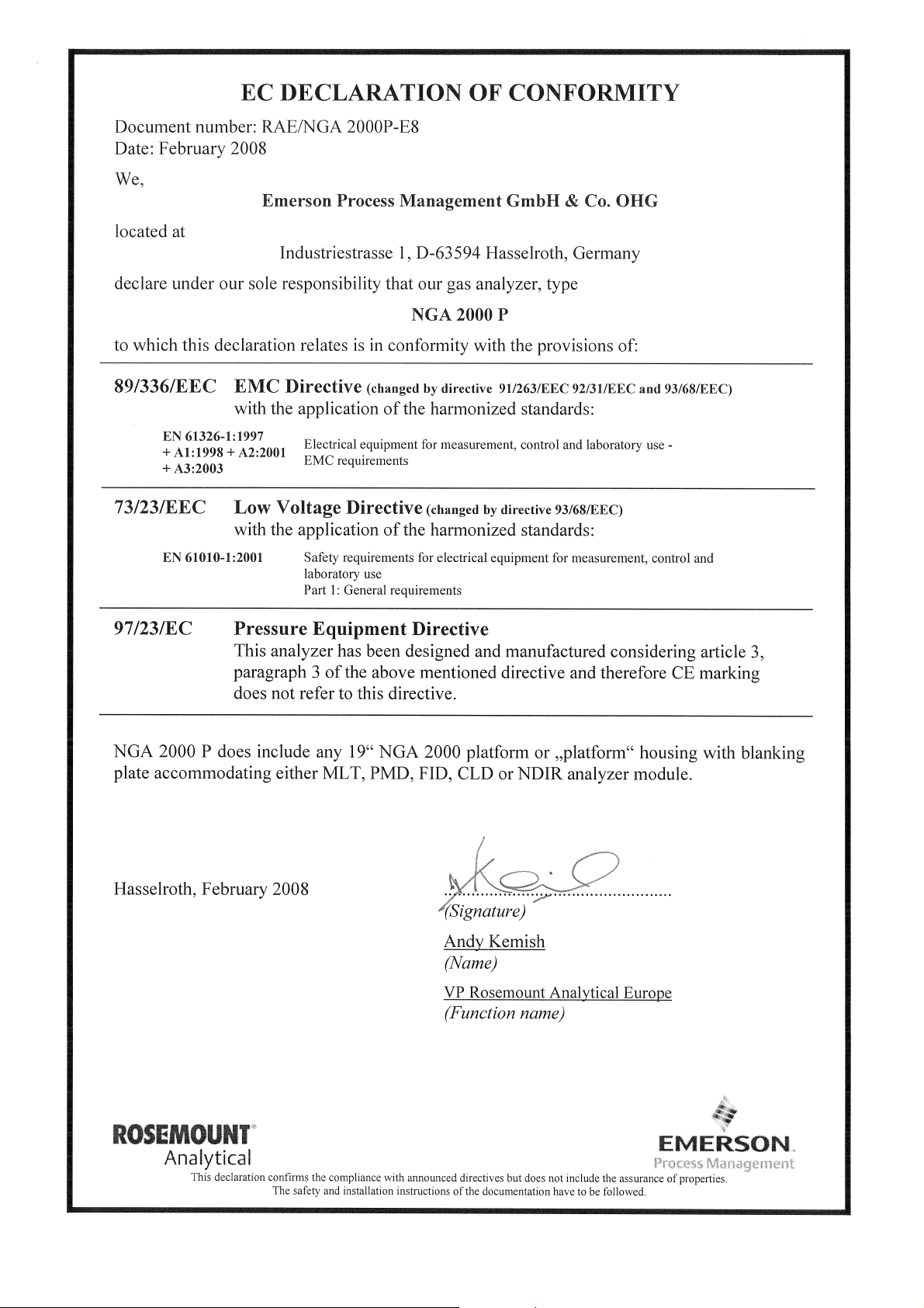
A-1 NGA 2000 P
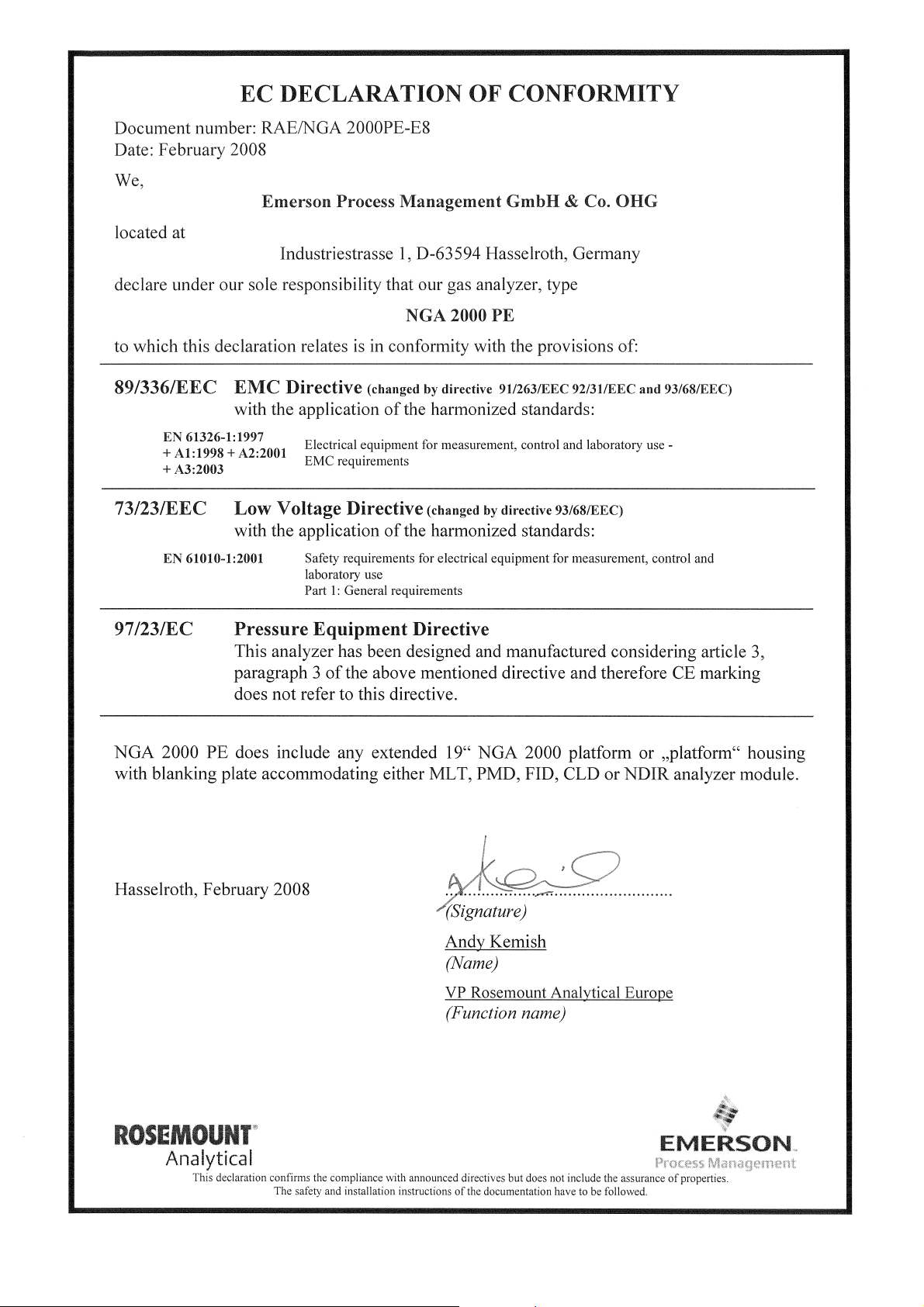
A-2 NGA 2000 PE
Instruction Manual
90002496
04/2008

Instruction Manual
90002496
04/2008
NGA 2000 Platform

Instruction Manual
90002496
04/2008
WORLD HEADQUARTERS
ROSEMOUNT ANAL YTICAL EUROPE
Emerson Process Management
GmbH & Co. OHG
Industriestrasse 1
63594 Hasselroth
Germany
T 49 6055 884 0
F 49 6055 884209
Emerson Process Management
Rosemount Analytical Inc.
6565 P Davis Industrial Parkway
Solon, OH 44139 USA
T 440.914.1261
Toll Free in US and Canada 800.433.6076
F 440.914.1271
e-mail: gas.csc@EmersonProcess.com
www.raihome.com
GAS CHROMA TOGRAPHY CENTER
AND LATIN AMERICA
Emerson Process Management
Rosemount Analytical Inc.
11100 Brittmoore Park Drive
Houston, TX 77041
T 713 467 6000
F 713 827 3329
NGA 2000 Platform
EUROPE, MIDDLE EAST AND AFRICA
Emerson Process Management
Shared Services Limited
Heath Place
Bognor Regis
West Sussex PO22 9SH
England
T 44 1243 863121
F 44 1243 845354
ASIA-PACIFIC
Emerson Process Management
Asia Pacific Private Limited
1 Pandan Crescent
Singapore 128461
Republic of Singapore
T 65 6 777 8211
F 65 6 777 0947
e-mail: analytical@ap.emersonprocess.com
© Emerson Process Management GmbH & Co. OHG 2007
 Loading...