


NGA 2000
N
ON
-D
ISPERSIVE INFRARED
A
NALYZER
Rosemount Analytical
M
ODULE

N
OTICE
T
HE INFORMATION CONTAINED IN THIS DOCUMENT IS SUBJECT TO CHANGE WITHOUT NOTICE
Pyrex® is a registered trademark of Corning Glass Works
®
Irtran
is a registered trademark of Eastman Kodak Co.
®
Teflon
Ty-Rap
and Viton® is a registered trademark of E.I. duPont de Nemours and Co., Inc.
®
is a registered trademark of Thomas & Betts Corp.
.
Manual Part Number 748332-D
June 1997
Printed in U.S.A.
Rosemount Analytical Inc.
4125 East La Palma Avenue
Anaheim, California 92807-1802

C
P
REFACE
PURPOSE/SAFETY SUMMARY........................................................................P-1
GLOSSARY ......................................................................................................P-4
SPECIFICATIONS..............................................................................................P-6
CUSTOMER SERVICE, TECHNICAL ASSISTANCE AND FIELD SERVICE ....P-8
RETURNING PARTS TO THE FACTORY .........................................................P-8
TRAINING ......................................................................................................P-8
DOCUMENTATION............................................................................................P-8
COMPLIANCES..................................................................................................P-9
ONTENTS
S
ECTION
1.1 OVERVIEW ...............................................................................................1-1
1.2 TYPICAL APPLICATIONS.........................................................................1-1
1.3 THEORY OF TECHNOLOGY....................................................................1-2
1.4 SAMPLE REQUIREMENTS ......................................................................1-4
1-5 PURGE KITS.............................................................................................1-5
1.6 FEATURES................................................................................................1-5
S
ECTION
2.1 UNPACKING..............................................................................................2-1
2.2 ASSEMBLY................................................................................................2-1
2.3 LOCATION ................................................................................................2-2
2.4 GASES ......................................................................................................2-2
2.5 ELECTRICAL CONNECTIONS .................................................................2-5
1. I
2. I
2.4.1 Specifications...............................................................................2-2
2.4.2 Connections.................................................................................2-3
NTRODUCTION
NSTALLATION
748332-D Rosemount Analytical June 1997
NGA Non-Dispersive Infrared Analyzer
i

C
ONTENTS
S
ECTION
3.1 OVERVIEW............................................................................................... 3-1
3.2 DISPLAY SCREENS.................................................................................3-1
3.2.1 RUN MODE DISPLAY............................................................................3-1
3.3 STARTUP PROCEDURE..........................................................................3-2
3.4 BINDING ...................................................................................................3-5
3.5 CALIBRATION ..........................................................................................3-5
3.6 LINEARIZATION.......................................................................................3-8
3.7 ROUTINE OPERATION............................................................................3-9
S
ECTION
4.1 OVERVIEW............................................................................................... 4-1
4.2 PCB REPLACEMENT...............................................................................4-2
4.3 POWER FUSE REPLACEMENT ..............................................................4-2
3. S
3.2.2 Menu Displays.............................................................................3-1
3.2.3 Help Displays...............................................................................3-2
4. M
TARTUP AND OPERATION
AINTENANCE AND TROUBLESHOOTING
4.4 MODULE FAN REPLACEMENT...............................................................4-2
4.5 CHOPPER MOTOR REPLACEMENT ......................................................4-3
4.6 SOURCE REPLACEMENT.......................................................................4-3
4.7 DETECTOR REMOVAL............................................................................4-3
4.8 FLOW SENSOR REPLACEMENT............................................................4-3
4.9 CASE TEMPERATURE SENSOR REPLACEMENT ................................4-4
4.10 THERMAL FUSE REPLACEMENT...........................................................4-4
4.11 OSCILLATOR TUNE/SOURCE BALANCE SHUTTER ADJUSTMENT....4-4
4-12 CLEANING CELLS ...................................................................................4-8
4-13 CELL DESICCANT ...................................................................................4-10
4.14 MODULATION CHECK.............................................................................4-10
S
ECTION
5.1 REPLACEMENT PARTS ..........................................................................5-1
5.
REPLACEMENT PARTS
A
PPENDIX
ii
A. I
DENTIFICATION MATRIX
June 1997 Rosemount Analytical 748332-DNGA Non-Dispersive Infrared Analyzer

NFRARED ANALYZER DATA SHEET
I
ENERAL PRECAUTIONS FOR HANDLING
G
ARRANTY
W
IELD SERVICE AND REPAIR FACILITIES
F
F
IGURES
1-1 NGA 2000 NDIR Analyzer Module (Typical - Actual configuration May
Vary)..............................................................................................1-3
1-2 NDIR Technology ......................................................................................1-4
2-1 Analyzer Module Installation Into Instrument Platform...............................2-1
2-2 Outline and Mounting Dimensions.............................................................2-4
2-3 NDIR Back Panel.......................................................................................2-5
2-4 NDIR Front Panel Electrical Connections..................................................2-5
2-5 NDIR Wiring Diagram................................................................................2-6
3-1 Run Mode Display.....................................................................................3-3
3-2 Main Menu Display....................................................................................3-3
3-3 Basic Controls Menu..................................................................................3-3
3-4 Expert Controls and Setup Menu...............................................................3-4
3-5 Technical Level Configuration Menu .........................................................3-4
3-6 Typical Help Screen...................................................................................3-4
3-7 Typical Linearization Curve, Linearizer OFF..............................................3-7
3-8 Operator-Determined Linearization Curve (Normalized)............................3-7
3-9 Display Screens (1 of 5)............................................................................3-10
3-10 Display Screens (2 of 5)............................................................................3-11
3-11 Display Screens (3 of 5)............................................................................3-12
3-12 Display Screens (4 of 5)............................................................................3-13
3-13 Display Screens (5 of 5)............................................................................3-14
4-1 Printed Circuit Board Fold-Out Panel Views..............................................4-2
4-2 Module Fan Assembly...............................................................................4-3
4-3 Motor/Source Assembly.............................................................................4-4
4-4 Cell, PCB Assembly (Exploded View)........................................................4-6
4-5 Oscillator Tune, Source Balance Shutter Adjustments..............................4-7
4-6 Detector Block (Exploded View) ................................................................4-7
4-7 Cell Disassembly.......................................................................................4-9
TORING HIGH PRESSURE CYLINDERS
& S
C
ONTENTS
T
ABLES
2-1. Cell Purging Times at Atmospheric Sample Pressure...............................2-2
3-1 NDIR Analyzer Module Alarms..................................................................3-6
4-1 Cell Desiccant............................................................................................4-10
748332-D Rosemount Analytical June 1997
NGA Non-Dispersive Infrared Analyzer
iii

C
ONTENTS
N
OTES
iv
June 1997 Rosemount Analytical 748332-DNGA Non-Dispersive Infrared Analyzer

P
REFACE
P
URPOSE/SAFETY SUMMARY
The purpose of this manual is to provide information concerning the components,
functions, installation and maintenance of this particular NGA 2000 module.
Some sections may describe equipment not used in your configuration. The user
should become thoroughly familiar with the operation of this module before operating
it. Read this instruction manual completely.
To avoid explosion, loss of life, personal injury and damage to this equipment
and on-site property, all personnel authorized to install, operate and service this
equipment should be thoroughly familiar with and strictly follow the instructions
in this manual. SAVE THESE INSTRUCTIONS.
If this equipment is used in a manner not specified in these instructions,
protective systems may be impaired.
DANGER
personal injury, death, or substantial property damage if the warning is ignored.
WARNING
personal injury, death, or substantial property damage if the warning is ignored.
CAUTION
personal injury or property damage if the warning is ignored.
NOTE
important but not hazard-related.
is used to indicate the presence of a hazard which
is used to indicate the presence of a hazard which
is used to indicate the presence of a hazard which
is used to indicate installation, operation or maintenance information which is
will
cause
can
cause
will or can
cause
severe
severe
minor
WARNING: ELECTRICAL SHOCK HAZARD
Operate this equipment only when covers are secured. Servicing requires
access to live parts which can cause death or serious injury. Refer servicing to
qualified personnel.
For safety and proper performance, this module must be connected to a
properly grounded three-wire source of electrical power.
748332-D Rosemount Analytical June 1997
NGA Non-Dispersive Infrared Analyzer
P-1
P
REFACE
WARNING: POSSIBLE EXPLOSION HAZARD
This equipment is not designed for and should not be used in the analysis of
flammable samples. Use of this equipment in this way could result in explosion
and death.
WARNING: POSSIBLE EXPLOSION HAZARD
Ensure that all gas connectors are made as labeled and are leak free. Improper
gas connections could result in explosion or death.
CAUTION: PRESSURIZED GAS
This module requires periodic calibration with a known standard gas. See
General Precautions for Handling and Storing High Pressure Gas Cylinders at
the rear of this manual.
CAUTION: HAND INJURY HAZARD
Dropping the front panel of the Platform while hand or fingers are inside either
case handle can cause serious injury.
P-2
June 1997 Rosemount Analytical 748332-DNGA Non-Dispersive Infrared Analyzer

P
REFACE
CAUTION: PARTS INTEGRITY
Tampering with or unauthorized substitution of components may adversely
affect safety of this product. Use only factory approved components for repair.
CAUTION: OVERBALANCE HAZARD
This Analyzer Module may tip instrument over if it is pulled out too far and the
Platform is not properly supported.
WARNING: OVER-VOLTAGE SPIKING
If this Analyzer Module is used with a non-Rosemount Analytical power supply,
adding Rosemount Analytical PN 903341 Current Protector in series with the
24V positive power line will prevent over-voltage spiking and resultant fuse
blowing when powering up the instrument.
Note
Apply leak test liquid to cell or detectors only as a last resort.
748332-D Rosemount Analytical June 1997
NGA Non-Dispersive Infrared Analyzer
P-3

P
REFACE
G
LOSSARY
NALYZER MODULE
A
The module that contains all sensor/detector components for development of a
Primary Variable signal; includes all signal conditioning and temperature control
circuitry.
ACKPLANE
B
The interconnect circuit board which the Controller Board, Power Supply, Analyzer
Module power and network cables, I/O Modules and Expansion Modules plug into.
ONTROL MODULE
C
The Operator Interface plus the Controller Board.
ONTROLLER BOARD
C
The computer board that serves as the Network Manager and operates the Display
and Keypad.
ISTRIBUTION ASSEMBLY
D
The Backplane and the card cages that hold I/O and Expansion Modules.
XPANSION MODULE
E
A circuit board that plugs into the Backplane from the front of the Platform and
performs special features not related to I/O functions.
I/O M
A circuit board that plugs into the Backplane from the rear of the Platform. Has a
connector terminal for communication with external data acquisition devices and
provides an input/output function.
ODULE
P-4
PERATOR INTERFACE
O
The Display and Keyboard.
June 1997 Rosemount Analytical 748332-DNGA Non-Dispersive Infrared Analyzer

P
REFACE
LATFORM
P
Any workable collection of the following: Controller Board, Power Supply, Distribution
Assembly, Enclosure and Operator Interface.
OWER SUPPLY
P
Any of a variety of components that provides conditioned power to other NGA 2000
components, from the Power Supply Board that plugs into the front of the Backplane
in a stand-alone instrument to several larger ones that can power larger collections of
modules and components.
RIMARY VARIABLE
P
The measured species concentration value from an Analyzer Module.
ECONDARY VARIABLE
S
Data placed on the network by a module regarding current status, e.g., sample flow,
source voltage and other diagnostic information.
OFTKEYS
S
The five function keys located below the front panel display; they assume the function
displayed directly above each on the display, a function dictated by software.
YSTEM
S
Any collection of Analyzer M odule(s), Platform(s) , I/O Module(s) and Expansion Modul e(s).
748332-D Rosemount Analytical June 1997
NGA Non-Dispersive Infrared Analyzer
P-5

P
REFACE
S
PECIFICATIONS
M
EASUREMENT SPECIES
R
ANGES
R
EPEATABILITY
M
INIMUM DETECTABLE
L
EVEL
N
OISE
L
INEARITY
R
ESPONSE TIME
D
RIFT (ZERO AND SPAN
E
FFECT OF
T
EMPERATURE
E
NVIRONMENT
A
MBIENT TEMPERATURE
E
FFECT OF FLOW
P
OWER REQUIREMENTS
:
:
:
:
:
:
:
:
- G
ENERAL
Heteroatomic gases such as ammonia (NH3), carbon dioxide
:
(CO2), carbon monoxide (CO), carbon monoxide + carbon
dioxide ethylene (C2H4), hexane (C6H14), methane (CH4), nitric
oxide (NO) and sulfur dioxide (SO2)
10 ppm fullscale to 100% fullscale (application-dependent); 4
fullscale selections, including suppressed zero ranges
1% of fullscale (at constant temperature)
±
0.1% CO2 (at 1 atm. sample pressure; application dependent)
<1% of fullscale, peak-to-peak
1% of fullscale with 4th order polynomial
±
.05 to 30 seconds (selectable) for 0 to 90% of fullscale
<±1% of fullscale/24 hours at constant temperature
):
(application dependent);
<±2% of fullscale/week at constant temperature (application
dependent)
<±1% of fullscale over any 10°C interval for rate of change no
greater than 10°C per hour (application dependent)
Location - Class B controlled, indoor, non-hazardous
0 to 45°C (32 to 113°F)
:
:
<1% of range when sample flow rate is changed by ≤250
ml/min. (No effect if flow rate is between 0 and 500 ml/min.)
24 VDC ±5%, 100 W max.; ripple and noise: <100 mV peak-to-
:
peak; line and load regulations: <±1%
S
PECIFICATIONS
T
EMPERATURE
F
LOW RATE
P
RESSURE
P
ARTICULATES
D
EWPOINT
M
ATERIALS IN CONTACT
WITH SAMPLE
:
:
:
:
:
P-6
- S
AMPLE
Non-flammable;: 0°C to 55°C (32°F to 138°F)
500 to 1400 ml/min.
Maximum 690 hPa-gauge (10 psig), higher pressure in
pressurized cell applications
:
filtered to <2 microns
<40°C (104°F), no entrained liquid
Gold plated Pyrex, sapphire, quartz, Irtran, FEP Teflon, Viton-
A, 316 stainless steel
June 1997 Rosemount Analytical 748332-DNGA Non-Dispersive Infrared Analyzer

P
REFACE
S
PECIFICATIONS
C
ASE CLASSIFICATION
D
IMENSIONS
W
EIGHT
M
OUNTING
M
AXIMUM LENGTH OF
LON C
:
:
ABLE
:
:
- P
HYSICAL
General purpose for installation in weather-protected areas
:
See Outline and Mounting Dimensions, Figure 2-3
Standard: 11 kg (24.2 lbs.); extended: 12.5 kg (27.5 lbs.)
Inside a Platform or custom-installed in a panel
1600 m (1 mile) between Analyzer Module and Platform
See the Preface Section of the Platform manual for specifications regarding Platform
related components.
748332-D Rosemount Analytical June 1997
NGA Non-Dispersive Infrared Analyzer
P-7

P
REFACE
C
USTOMER SERVICE
For order administration, replacement Parts, application assistance, on-site or factory
repair, service or maintenance contract information, contact:
R
ETURNING PARTS TO THE FACTORY
Before returning parts, contact the Customer Service Center and request a Returned
Materials Authorization (RMA) number. Please have the following information when
you call:
Number.
Prior authorization by the factory must be obtained before returned materials will be
accepted. Unauthorized returns will be returned to the sender, freight collect.
When returning any product or component that has been exposed to a toxic, corrosive
or other hazardous material or used in such a hazardous environment, the user must
attach an appropriate Material Safety Data Sheet (M.S.D.S.) or a written certification
that the material has been decontaminated, disinfected and/or detoxified.
Model Number, Serial Number, and Purchase Order Number or Sales Order
, T
ECHNICAL ASSIST ANCE AND FIELD SERVICE
Rosemount Analytical Inc.
Process Analytical Division
Customer Service Center
1-800-433-6076
Return to:
Rosemount Analytical Inc.
4125 East La Palma Avenue
Anaheim, California 92807-1802
T
RAINING
A comprehensive Factory Training Program of operator and service classes is
available. For a copy of the
the Technical Services Department at:
D
OCUMENTATION
The following NGA 2000 Non-Dispersive Infrared Analyzer instruction materials are
available. Contact Customer Service or the local representative to order.
748332 Instruction Manual (this document)
Current Operator and Service Training Schedule
Rosemount Analytical Inc.
Phone: 1-714-986-7600
FAX: 1-714-577-8006
contact
P-8
June 1997 Rosemount Analytical 748332-DNGA Non-Dispersive Infrared Analyzer
C
9
6
OMPLIANCES
This product may carry approvals from several certifying agencies, including Factory
Mutual and the Canadian Standards Association (which is also an OSHA accredited,
Nationally Recognized Testing Laboratory), for use in non-hazardous, indoor locations
P
REFACE
FM
APPROVED
Rosemount Analytical Inc. has satisfied all obligations from the European
Legislation to harmonize the product requirements in Europe.
This product complies with the standard level of NAMUR EMC.
Recommendation (May 1993).
This product satisfies all obligations of all relevant standards of the EMC framework in
Australia and New Zealand.
®
97-C219
NAMUR
N
748332-D Rosemount Analytical June 1997
NGA Non-Dispersive Infrared Analyzer
P-9

P
REFACE
N
OTES
P-10
June 1997 Rosemount Analytical 748332-DNGA Non-Dispersive Infrared Analyzer

I
NTRODUCTION
1
1.1 OVERVIEW
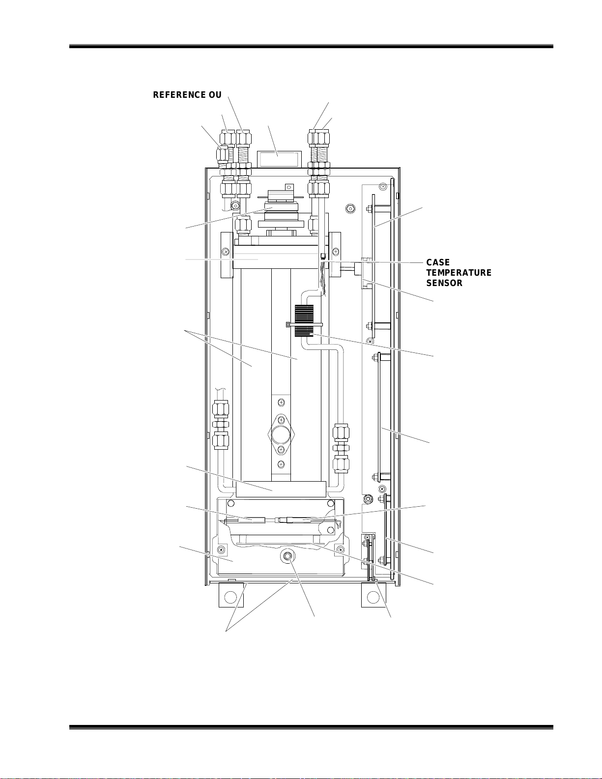
This manual describes the Non-Dispersive Infrared (NDIR) Analyzer Module of
Rosemount Analytical's NGA 200 Series of gas analysis components. See Figure 1-1.
The NDIR Analyzer Module is designed to continuously determine the concentration
of oxygen in a flowing gaseous mixture. The concentration is expressed in one of
three fashions:
parts-per-million
•
percent of composition
•
percent of fullscale
•
The user can obtain an output that is linear with concentration by initiating a linearizer,
which is based on a fourth-order polynomial. The linearizer is incorporated in the
Analyzer Module's electronic circuitry and is adjustable through interconnection with
the network.
The entire Analyzer Module is designed as a slide-in module (if configured in standalone instrument fashion), removable from the front of the Platform, with gas
connections made from the rear. All electronics relative to sample detection and
conditioning are included in this module.
1.2 TYPICAL APPLICATIONS
The NDIR Analyzer Module is designed to cover a wide range of process, stack and
automotive applications. Typical measurements include:
HEMICAL AND PETROLEUM
C
Carbon dioxide: Manufacture of ethylene oxide, phthalic anhydride and
•
ammonia; nitrogen generation; and producer gas monitoring
Carbon Monoxide: Stack monitoring
•
Methane: Ammonia manufacture
•
Acetylene: Manufacture of acetylene, acrylonitrile, and vinyl chloride
•
Sulfur Dioxide: Sulf uric acid stack gas
•
748332-D Rosemount Analytical June 1997
NGA Non-Dispersive Infraraed Analyzer
1-1

I
NTRODUCTION
OOD AND AGRICULT URE
F
EROSPACE AND OCEANOGRAPHY
A
ETALS AND CERAMICS
M
Carbon Dioxide and Water Vapor: Blanketing of perishables, fermentation
•
processes, photosynthesis studies, personnel protection
Carbon Dioxide, Carbon Monoxide, and Water Vapor: Diving and space
•
chambers
Carbon Dioxide: Monitoring of producer gas, steel converting, manufacture of
•
cement, soaking pit, heat treating
Carbon Monoxide: Inert gas generation, producer gas monitoring, rotary kiln
•
roasting, tin plate annealing, steel converting, aluminum power processing,
porcelain kilns, tunnels
Water Vapor: Heat treating, hydrogen brazing, nickel and chrome plating
•
Sulfur Dioxide: Flash smelting
•
Ammonia: Ammonia dissociation
•
1.3 THEORY OF TECHNOLOGY
Inside of the Analyzer Module, two equal-energy infrared beams are directed through
two parallel optical cells, a flow-through sample cell and a reference cell. The
reference cell may be sealed or may contain a continuously flowing reference gas.
(See Figure 1-2.)
The infrared radiation is interrupted by a chopper at a frequency of 5 Hz.
During analysis, a portion of the infrared radiation is absorbed by the component of
interest in the sample. The quantity of infrared radiation that is absorbed is
proportional to the component concentration.
1-2
June 1997 Rosemount Analytical 748332-DNGA Non-Dispersive Infraraed Analyzer
REFERENCE OUT
(
)
REFERENCE IN
PURGE GAS IN
CHOPPER MOTOR
FAN
SAMPLE OUT
(BOTTOM)
SAMPLE IN
POWER SUPPLY
BOARD
I
NTRODUCTION
SOURCE
CELLS
DETECTOR
THERMAL FUSE
DETECTOR COVER
CASE
TEMPERATURE
SENSOR
PRESSURE
COMPENSATION
BOARD
FLOW SENSOR
MICRO BOARD
DETECTOR
TEMPERATURE
CONTROL RTD
SIGNAL BOARD
OPTION
IGURE
F
748332-D Rosemount Analytical June 1997
1-1. NGA 2000 NDIR A
SHUTTER ADJUST
ACCESS HOLES
NALYZER MODULE (TYPICAL
ONFIGURATION MAY VARY
C
OSCILLATOR
TUNE ADJUST
)
OSCILLATOR
BOARD
NETWORK INPUT
MODULE
CTUAL
- A
NGA Non-Dispersive Infraraed Analyzer
1-3

I
NTRODUCTION
The detector is a "gas microphone" based on the Luft principle. The detector is
generally filled with the same gas being analyzed. The infrared energy is therefore
absorbed at the same wavelengths in the detector as that in the sample cell, making
the detector specific for the analyzed component. The detector converts the
difference in energy between sample and reference cells to a capacitance change.
This change, which is proportional to component concentration, is processed and
expressed as the primary variable on the network.
Other modules comprising the NGA 2000 unit then use this variable for a variety of
purposes (e.g., expressing the gas concentration on the Front Panel Display or
sending it to external data acquisition devices).
For a general understanding of the electrical interconnections in the NDIR Analyzer
Module, see Figure 2-5.
IGURE
F
INFRARED
SOURCE
REFERENCE
CELL
DETECTOR
STATIONARY
PLATE
1-2. NDIR T
DIAPHRAGM,
DARK STATE
ECHNOLOGY
CHOPPER
SAMPLE IN
SAMPLE
CELL
SAMPLE
DIAPHRAGM,
DISTENDED
COMPONENT OF INTEREST
NON-INTERFERING COMPOUNDS
1.4 SAMPLE REQUIREMENTS
Maximum allowable sample pressure is 690 hPa-gauge (10 psig) for a standard
configuration NDIR that has a flow restrictor which sets the flow at between 0.5 L/min.
to 1 L/min. Special high pressure cells (up to 10,350 hPa-gauge, 150 psig) are
available. Sample temperature range is 0°C to 55°C, and maximum dewpoint is 40°C.
The sample must be filtered to exclude particulates larger than 2 microns in size.
Consult factory for special configurations with specifications outside of those listed
above.
1-4
June 1997 Rosemount Analytical 748332-DNGA Non-Dispersive Infraraed Analyzer

1.5 PURGE KITS
A purge kit for the motor source or motor source/flowing reference cell accompanies
some NDIR modules. The purpose of these kits is to improve performance and
accuracy through the reduction of ambient CO2 interference.
protection from explosion hazard.
The purge gas vents into the case, which has no
They do not provide
outlet fitting for these types of purge gases.
1.6 FEATURES
Among the features available in the NDIR Analyzer Module are:
Pressure compensation for barometric fluctuations (optional)
•
Flow sensing
•
I
NTRODUCTION
748332-D Rosemount Analytical June 1997
NGA Non-Dispersive Infraraed Analyzer
1-5

I
NTRODUCTION
N
OTES
1-6
June 1997 Rosemount Analytical 748332-DNGA Non-Dispersive Infraraed Analyzer
I
NSTALLATION
2
2.1 UNPACKING
If the NDIR Analyzer Module is received as a separate unit, carefully examine the
shipping carton and contents for signs of damage. Immediately notify the shipping
carrier if the carton or contents is damaged. Retain the carton and packing material
until all components associated with the Analyzer Module are operational.
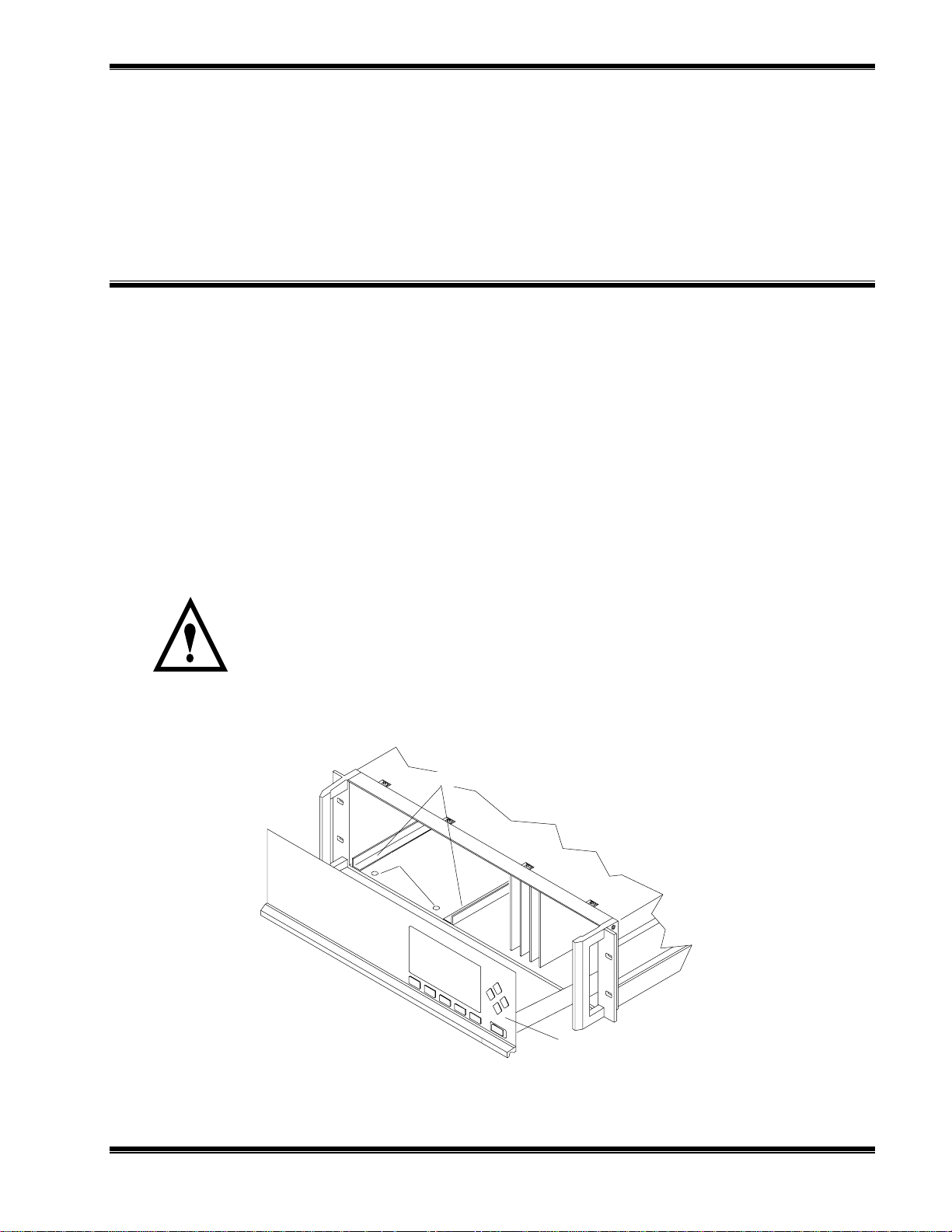
2.2 ASSEMBLY
If the NDIR Analyzer Module requires assembly with other components (e.g., the
Platform and associated I/O Modules), do so at this time. Following the guides on the
bottom left and bottom center of the Platform, carefully slide the Analyzer Module
halfway into place.
CAUTION: HAND INJURY HAZARD
Do not place hands or fingers in the Platform front handles when front panel is
open. Dropping the front panel of the Platform while hand or fingers are inside
either handle can cause serious injury.
ANALYZER MODULE GUIDES
PIN SEATS
DISENGAGED FRONT PANEL
IGURE
F
2-1. A
NALYZER MODULE INSTALLATION INTO INSTRUMENT PLATFORM
748332-D Rosemount Analytical June 1997
NGA Non-Dispersive Infrared Analyzer
2-1

I
NSTALLATION
Lift the spring-loaded pins on the front of the Analyzer Module, and carefully slide it
the rest of the distance. Secure the module in position by releasing the pins, which
seat in the available holes in the bottom of the case (see Figure 2-1). If the module
and Platform are difficult to assemble, remove the module, ensure the top cover of the
module is firmly seated on the hold-down screws, and repeat the assembly procedure.
Install I/O Module(s) according to guidelines in the I/O manual. After startup and
calibration have been performed, secure the front panel with the six screws provided.
2.3 LOCATION
Install the NDIR Analyzer Module in a clean, non-hazardous, weather protected,
vibration free location free from extreme temperature variations. For best results,
install the instrument near the sample stream to minimize sample transport time.
Operating ambient temperature is 0oC to 45oC (32oF to 113oF). Sample dewpoint is
40°C or less.
Note
Unrestricted air flow in the rear of the Analyzer Module is critical to its
performance and reliability.
CELL LENGTH CELL VOLUME
mm inch without inlet tube cell with inlet tube at 750 mm Hg
3 0.118 0.85 12 2 sec.
4 0.157 1.14 12 2 sec.
8 0.315 2.28 13 2 sec.
16 0.630 3.56 16 2 sec.
32 1.25 9.12 20 2 sec.
64 2.52 18.24 25 3 sec.
128 4.03 35.48 44 3 sec.
232 9.13 65.12 73 6 sec.
343 13.50 97.76 105 13 sec.
381 15.00 108.60 116 14 sec.
ABLE
T
2-1. C
2.4 GASES
2.4.1 S
PECIFICATIONS
TOTAL VOLUME INCCTIME FOR 2 VOLUMES AT
IN CC
ELL PURGING TIMES AT ATMOSPHERIC SAMPLE PRESSURE
2 SCFH (1L/MIN)
2-2
ALIBRATION GASES
C
All applications require a zero standard gas to set the zero point on the display and
external data acquisition devices. if the factory provided Calibration and Data Sheet
June 1997 Rosemount Analytical 748332-DNGA Non-Dispersive Infrared Analyzer

I
NSTALLATION
(in the rear of the manual) specifies a background gas, use this as a zero gas. If a
background gas is not specified, use dry nitrogen.
Span gas should be between 75% and 100% of fullscale span. Flowing reference (if
used) should be dry nitrogen.
LOW RATE
F
Recommended sample flow rate is 1 to 2 SCFH (500 TO 1000 cc/min). A lower flow
rate will not affect readings but may result in an undesirable time lag. Excessive flow
can produce increases cell pressurization and reading error.
At higher cell pressures, the nonlinearity of the calibration curve increases. Therefore,
the calibration curve should be redrawn for higher flow rates. Also, the effect of
increased cell pressurization can be negated if the same flow rate is used for sample,
zero and span gases. But, if flow is high enough to cause elevated pressure, careful
control (tighter tolerance) of flow rate is required to avoid errors.
If low is kept at or below 2 SCFH (1 L/min), sample and instrument temperatures
reach equilibrium regardless of strea m temperature (within sp ecifications; 0 to 55°C).
At extremely high flow rates, this may not be true, although no such effect has been
noted up to 18 SCFH (9 L/min).
See Table 2-1 for cell purging times at atmospheric sample pressure.
AMPLE PRESSURE/FILTRATION
S
Sample should be introduced to the Analyzer Module at a maximum 690 hPa-gauge
(10 psig). Pressurized applications are available, which require pressurized cells and
careful control of flow rates, consult factory for these applications. Sample should be
filtered for particulates down to two microns.
EAK TEST
L
The Analyzer Module is completely tested at the factory for gas leakage. The user is
responsible for testing for leakage only at the inlet and outlet fittings on the rear panel.
The user is also responsible for internal leak testing periodically and if any internal
pneumatic components are adjusted or replaced (with a test procedure chosen by the
user).
2.4.2 C
ONNECTIONS
(See Figure 2-3) Connect inlet and outlet lines for sample/zero/span and flowing
reference (if applicable) to appropriately labeled fittings on the rear panel. All four
connections are 1/4 inch ferrule-type compression fittings.
748332-D Rosemount Analytical June 1997
NGA Non-Dispersive Infrared Analyzer
2-3

I
[
]
[28]
NSTALLATION
4.3
[109]
8.4
[213]
6.2
[157]
8.2
[208]
[15]
.6
2.8
[71]
[13]
.5
.6
[15]
1.1
1.1
[27]
1.1
[28]
20.0
[508.0]
STANDARD
24.8
[628.7]
EXTENDED
6.0
[152]
STANDARD
8.4
213
17.41
[142.2]
22.41
[569.2]
EXTENDED
1.6
[40]
G. POWER CABLE TO NETWORK.
F. NETWORK CABLE CONNECTIONS TO PLATFORM.
E. PURGE GAS IN: 1/4" O.D. TUBE FITTING.
D. REFERENCE IN: 1/4" O.D. TUBE FITTING.
C. REFERENCE OUT: 1/4" O.D. TUBE FITTING.
B. SAMPLE OUT: 1/4" O.D. TUBE FITTING.
A. SAMPLE IN: 1/4" O.D. TUBE FITTING.
5.6
[143]
1.0
[25]
DIMENSIONS
5. MODULE TO BE IN STALLED WITHIN ±15° OF HORIZONTAL.
4. POWER REQUIREMENTS: 24 VDC 3.5 A.
3. ELECTRICAL INSTALLATION MUST BE IN COMPLIANCE WITH NATIONAL ELECTRICAL
CODE (ANSI/NFPA 70) AND/O R ANY APPLICABLE NATIONAL OR LOCAL CODES.
2. MODULE IS NOT WEATHERPROOF.
1. APPROXIMATE WEIGHT: 24.2 LB (11.0 kg).
IGURE
F
2-2 O
2-4
UTLINE AND MOUNTING DIMENSIONS
June 1997 Rosemount Analytical 748332-DNGA Non-Dispersive Infrared Analyzer
INCH
[mm]

2.5 ELECTRICAL CONNECTIONS
Note
Electrical connections must be in compliance with National Electrical Code
(ANSI/NFPA 70) and/or any applicable national or electrical codes.
Two electrical connections are required on the Analyzer Module; POWER and
NETWORK. See Figure 2-4. On the Analyzer Module, two NETWORK connections
are available, either of which is appropriate for : 1) interconnection with Backplane of
the Platform (see Platform instruction manual) or 2) "daisy chaining" with other NGA
2000 components.
Connect Analyzer Module POWER 24 VDC power source, either the Platform or
external power source.
FAN
I
NSTALLATION
IGURE
F
OUT
SAMPLE
IN
10 PSI M AX
(69 kPa MAX)
Note: Reference and purge gas connections are applicable only to certain applications.
2-3. NDIR B
ACK PANEL
OUT
REFERENCE
IN
10 PSI M AX
(69 kPa MAX)
PURGE IN
15 PSI (103 kP a) MAX
NETWORK 1
NETWORK 2
POWER
IGURE
F
748332-D Rosemount Analytical June 1997
2-4. NDIR F
RONT PANEL ELECTRICAL CONNECTIONS
FUSE
NGA Non-Dispersive Infrared Analyzer
2-5

I
NSTALLATION
SAMPLE J2-1
SOURCE J2-2
REFERENCE J2- 3
SOURCE J2-4
FLOW SENSOR
FAN ASSEMBLY
MODULATION CHECK
HEATSINK/SOURCE
MOTOR ASSEMBLY
REF S O URCE
SAMPLE SOURCE
J2
J1
J15
J14
RESISTOR
DRIVER
SOURCE ASSY
J4
POWER
SUPPLY
BOARD
J6 J10
J9
PRESSURE
COMPEN SATION
BOARD
J7
1 2 3 4
J5
1 2
CHASSIS
GROUND
J3
J11
J8
FUSE, THERMAL
CUTOFF
RTD, TEMP CTRL
J4 J5 J6
J1
COMPUTER BOARD
J2
J3
CASE TEMPERATURE
SENSOR
HEATER
SENSOR °C
DETECTOR BASE
RECORDER
J5
J7
SIGNAL
J4
BOARD
BOARD
J6
J3 J1
J2
J7
°°°°
C
OSCILLATOR
J1
OUTPUT
J5
LON/POWER
BOARD
IGURE
F
2-5. NDIR W
IRING DIAGRAM
2-6
June 1997 Rosemount Analytical 748332-DNGA Non-Dispersive Infrared Analyzer

S
TARTUP AND OPERATION
3
3.1 OVERVIEW
Prior to initial startup, the user should leak test the module as outlined in Section 2.
For the remainder of this section, Analyzer Module interconnection with a Platform or
some interfacing component will be assumed. Display and Keypad information shall
refer to that which the user can expect to see and do with regard to the Front Panel of
the Platform.
(For a complete description of Platform Front Panel controls and indicators, see
Section 1 of the Platform Components instruction manual.)
3.2 DISPLAYS SCREENS
Three kinds of Display Screens are available to the user (see Figures 3-1 through
3-6.):
Run Mode
•
Menu
•
Help
•
3.2.1 R
3.2.2 M
UN MODE DISPLAY
The Run Mode is the normal mode of operation. In this mode, the Display will show
current gas measurement, the component of interest, the current operations of the
softkeys, a graphic bar representing the displayed concentration as a percent of
fullscale, and up to 4 user-selectable secondary variables and associated bargraphs.
If more than one Analyzer Module is connected to the system, the Run Mode display
will show as many as four gas measurements on a single screen. Alarm messages
may also appear on the display (See Table 3-1).
ENU DISPLAYS
The Menu structure enables the user to access data and functions, and put
information onto the network.
The Main Menu (see Figure 3-2) is subdivided into three levels of control based
748332-D Rosemount Analytical June 1997
NGA 2000 Non-Dispersive Infrared Analyzer
3-1

S
TARTUP AND OPERATION
generally on which personnel is likely to use it: Basic Controls, Expert Controls and
Setup, and Technical Controls. (See Figures 3-3 through 3-5.) Many layers of the
menu structure are described at appropriate places throughout this manual.
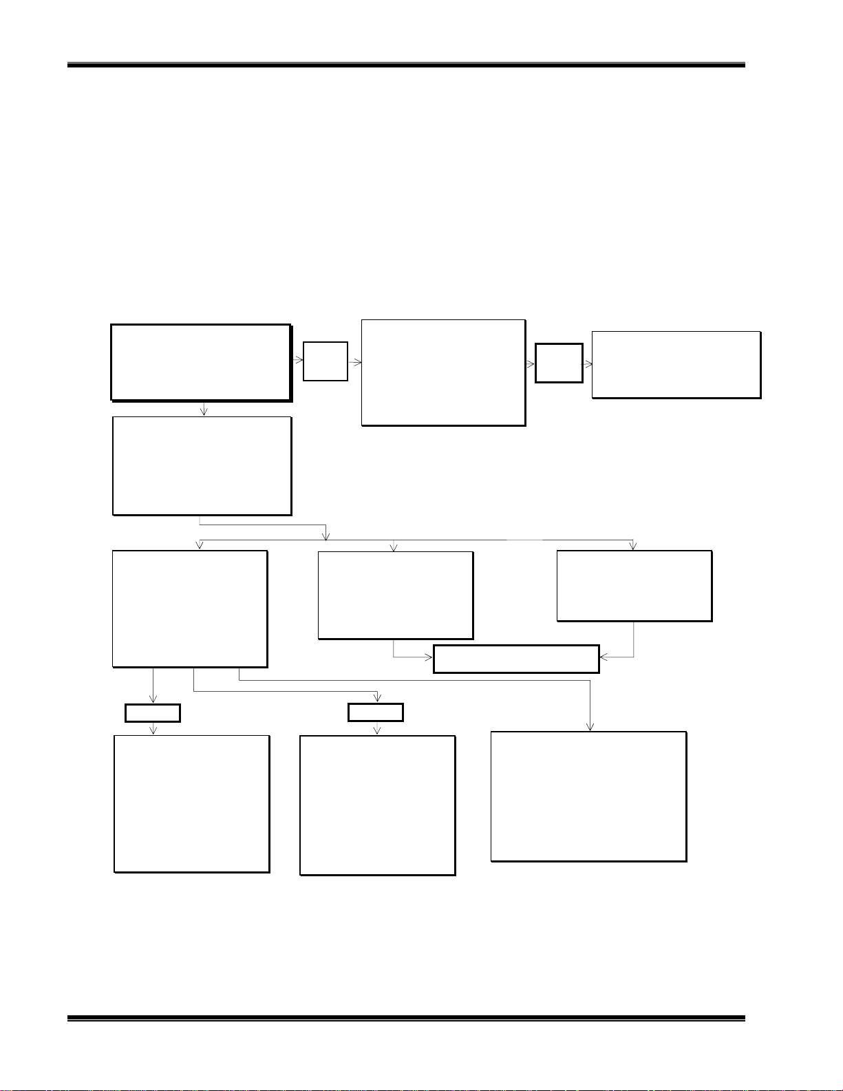
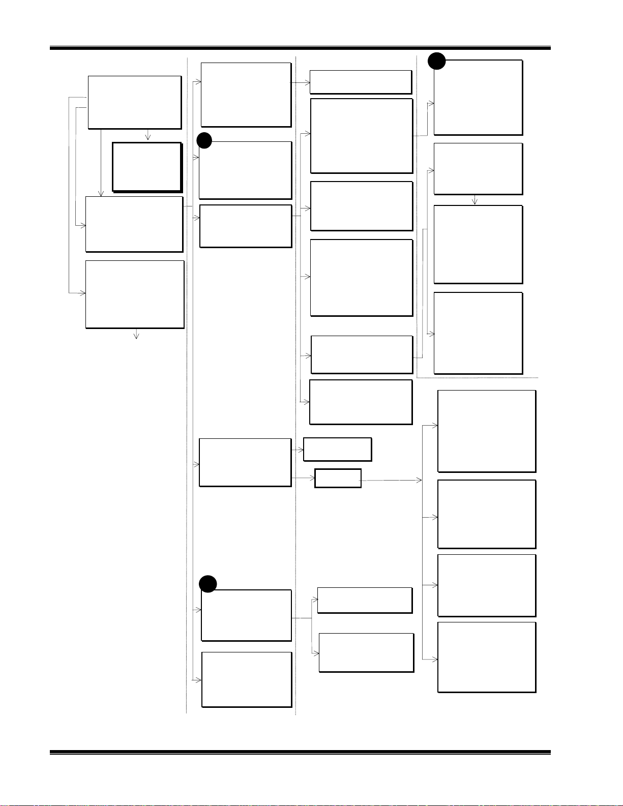
See Figures 3-9 through 3-13 for flow charts depicting Menu screens related to this
Analyzer Module.
From the Run Mode display, press the MENUS softkey to gain access to the Main
Menu. (See Figure 3-2.)
3.2.3 H
ELP DISPLAYS
The Help structure is on-line "tutorial," context-sensitive and topic-interconnected, so
that the user can practically operate NGA 2000 without need of an instruction manual.
3.3 STARTUP PROCEDURE
Introduce zero gas into SAMPLE INLET and reference and source purge gas, if
applicable, into their respective inlets. Ensure that gas pressures are set to
requirements listed on the Specifications page of the Preface section of this manual.
Apply power to the NDIR Analyzer Module. If it is associated with a Platform, do this
by plugging in the Platform to a power source. The Platform has no ON/OFF power
switch. Once power has been supplied to the Platform, the NDIR Analyzer Module will
be energized.
If the user's system contains only one Analyzer Module, all system components, the
Controller Board and the network "self-install" (bind together) during initial startup. If
the system contains more than one Analyzer Module, the startup procedure will
interrogate the network to locate and identify all components on the network. The
user will have to bind appropriate combinations of components after the startup
sequence.
3-2
After the warm-up period (about one hour for the NDIR Analyzer Module), all modules
are completely functional.
Check the tune and detector signal values against the factory settings listed in the
Diagnostic Service menus. If both settings are within ±5% tolerance of factory setting,
go to section 3.4 for binding and 3.5 for calibration. If not, refer first to section 4.11 for
instructions about oscillator tune/source balance shutter adjustments
June 1997 Rosemount Analytical 748332-DNGA 2000 Non-Dispersive Infrared Analyzer

Analyzer PQ 322-14
y
y
y
y
23.2 % CO
S
TARTUP AND OPERATION
IGURE
F
3-1. R
0 ppm
Secondar
Secondar
Secondar
Secondar
Variable: XXXX
Variable: XXX
Variable: XXXX
Variable: XXXX
Display Parms. Menu Dual Info
F1 F2 F3 F4 F5
UN MODE DISPLAY
23.2 % CO Analyzer XXXXXXXX
Basic Controls
Expert controls and setup ...
(Operational configuration)
Technical level configuration ...
(Diagnostic and manufacturing/service)
Delete alarm message!
Display Parms. Info
50
Main Menu
IGURE
F
IGURE
F
3-2. M
3-3. B
F1
F2 F3 F4 F5
AIN MENU DISPLAY
23.2 % CO Analyzer XXXXXXXX
Measurement range Numbers:
Range upper limit: 25%
Range and functional control: Local
Calibration…
Status: Ready
Home Escape Zero Span Info
F1
F2 F3 F4 F5
ASIC CONTROLS MENU
Basic Controls
748332-D Rosemount Analytical June 1997
NGA 2000 Non-Dispersive Infrared Analyzer
3-3

S
g
p
p
p
TARTUP AND OPERATION
23.2 % CO Analyzer XXXXXXXX
ert controls and setu
Ex
Expert analyzer controls ...
Auxiliary module controls ...
System set up ...
Analyzer module set up ...
Auxiliary module set up ...
Home Escape Info
IGURE
F
IGURE
F
3-4. E
3-5. T
F1
F2 F3 F4 F5
XPERT CONTROLS AND SETUP MENU
23.2 % CO Analyzer XXXXXXXX
Technical confi
System set up ...
Service menus...
Diagnostic menus...
Other module diagnostic menus...
listing of all modules...
Status: normal
uration menu
Home Info
F1
F2 F3 F4 F5
ECHNICAL LEVEL CONFIGURATION MENU
IGURE
F
3-4
3-6. T
23.2 % CO Analyzer XXXXXXXX
Main Menu Hel
The Main Menu for the analyzer system.
Note that this menu refers to the particular
analyzer selected from t he run screen, when
used in a system. The s oftkey marked “HOME”
will always return you to this screen.
Help menu system...
Help on help...
Keyboard controls...
Editing controls.. .
Home Escape Map
F1 F2 F3 F4 F5
YPICAL HELP SCREEN
June 1997 Rosemount Analytical 748332-DNGA 2000 Non-Dispersive Infrared Analyzer

S
TARTUP AND OPERATION
3.4 BINDING
To achieve full coordination between Analyzer Modules and associated I/O Modules,
the user must bind those components together in the System Set Up portion of the
Technical Configuration Menu
in software. (See Figure 3-12 of this manual and
Section 1.5 of the I/O Modules manual for binding instructions.)
3.5 CALIBRATION
Calibration can be executed from the
be entered only through
the Expert Controls and Setup
3-11 for display screen paths.
To calibrate the Analyzer Module, introduce zero gas into the SAMPLE INLET, and do
the following:
1. If the multi-Analyzer Module, split Run Mode display is shown, press the DISPLAY
softkey until the desired Analyzer's Run Mode display is acquired.
Basic Controls
menu. Calibration gas data can
menu. See Figures 3-9 and
2. Press the MENUS softkey to enter the
selections from the
Main Menu
: Expert Controls and Setup, Analyzer Module
Main Menu
and make the following
Setup, Calibration Gases.
3. Input appropriate data in the
4. Press the HOME softkey to return to the
Calibration Gas List
Main Menu.
menu.
5. Use the ↓ arrow key to select Basic Controls.
6. Press the ZERO softkey to enter the
Analyzer Zero
menu, press ZERO again and
wait.
7. Introduce span gas into the SAMPLE INLET, press SPAN softkey to enter the
Analyzer Span
8. Press HOME to re-enter the
menu, press SPAN again and wait.
Main Menu.
9. Press DISPLAY softkey for the Run Mode display.
If the user is unable to calibrate the Analyzer Module (i.e., when ZERO or SPAN is
initiated, nothing happens), a possible solution relates to the use of an incorrect gas
for zeroing or spanning (e.g., using a high concentration gas to zero or a zero gas to
span the Analyzer Module). Simply recalibrating with the appropriate gas(es) will not
correct the problem because the ZERO OFFSET or SPAN FACTOR has been set to
an extreme value in the process.
To remedy the problem, do the following:
1. Select the following from the
Module Set Up, and Calibration Parameters.
748332-D Rosemount Analytical June 1997
Main Menu
: Expert Controls and Setup, Analyzer
NGA 2000 Non-Dispersive Infrared Analyzer
3-5

S
TARTUP AND OPERATION
2. Using the ↓ arrow, select Zero Ranges, press ENTER and, using the up/down
arrows, toggle to SEPARATE. Do the same for the Calibrate Ranges selection. Do
not press ESCAPE at any time unless retention of prior settings is desired.
3. Return to the
Main Menu
and make the following selections: Expert Controls and
Setup, Expert Controls, CAL DATA softkey, FACTORS softkey, and Range 1 (2, 3,
4) Factors (do Steps 4 and 5 for each range).
4. Select Zero Offset, press ENTER, adjust the value to 500000 with the ↑ and
arrow keys, and press ENTER. Do not press ESCAPE at any time unless retention
of prior settings is desired.
5. Refer to the Data Sheet in the rear of this manual for Span Factors as originally set
at the factory. Select Span Factor, press ENTER, adjust the value to match the
values on the Data Sheet with the ↑ and ↓ arrow keys, and press ENTER. If Data
Sheet is not available, enter 0.000015 with the ↑ and ↓ arrow keys, and press
ENTER. Do not press ESCAPE unless retention of prior settings is desired.
6. Attempt to recalibrate the Analyzer Module according to the procedure outlined at
the beginning of Section 3.4. If recalibration fails, return to the
Range Factors
menu, readjust factors and try calibrating again.
Another cause of failure to calibrate is the following: The value for "Maximum range"
is lower than the upper limit value for the range in use. See the
Range Settings
menu for this information (See Figure 3-11).
DISPLAY MESSAGE DESCRIPTION TYPE
BAROMETER System Barometer WARNING
CASE TEMP Case Temperature WARNING
CHOP SPEED Chopper Speed WARNING
CRUDE NOISE Calculated Noise WARNING
DET SIG Detector Signal WARNING
DET TEMP Detector Temperature WARNING
LIN ERROR Linearizer Error WARNING
N15 VOLTS Power Supply, -15V WARNING
P12 VOLTS Power Supply, +12V WARNING
P15 VOLTS Power Supply, +15V WARNING
P24 VOLTS Power Supply, +24V WARNING
P5 VOLTS Power Supply, +5V WARNING
PERCENT MOD Percent Modulation WARNING
RAW SIGNAL Raw Signal WARNING
SVFLOW Sample Bypass Flow WARNING
SW ERROR Software Error FAILURE
↓
ABLE
T
3-6
3-1. NDIR A
NALYZER MODULE ALARMS
June 1997 Rosemount Analytical 748332-DNGA 2000 Non-Dispersive Infrared Analyzer
READING
% FULLSCALE
S
100 %
50 %
0 %
0 500 1000 1500 2000 2500 3000 3500 4000 4500 5000
TARTUP AND OPERATION
IGURE
F
3-7. T
CONCENTRATION
NORMALIZED
YPICAL LINEARIZATION CURVE
Display ppm
1
0.9
0.8
0.7
0.6
0.5
0.4
0.3
0.2
0.1
CONCENTRATION
ppm
INEARIZER
, L
OFF
0
0 0.1 0.2 0.3 0.4 0.5 0.6 0.7 0.8 0.9
IGURE
F
748332-D Rosemount Analytical June 1997
3-8. O
PERATOR-DETERMINED LINEARIZATION CURVE (NORMALIZED
READINGS, NORMALIZED
(Axis Reversed)
NGA 2000 Non-Dispersive Infrared Analyzer
)
3-7

S
TARTUP AND OPERATION
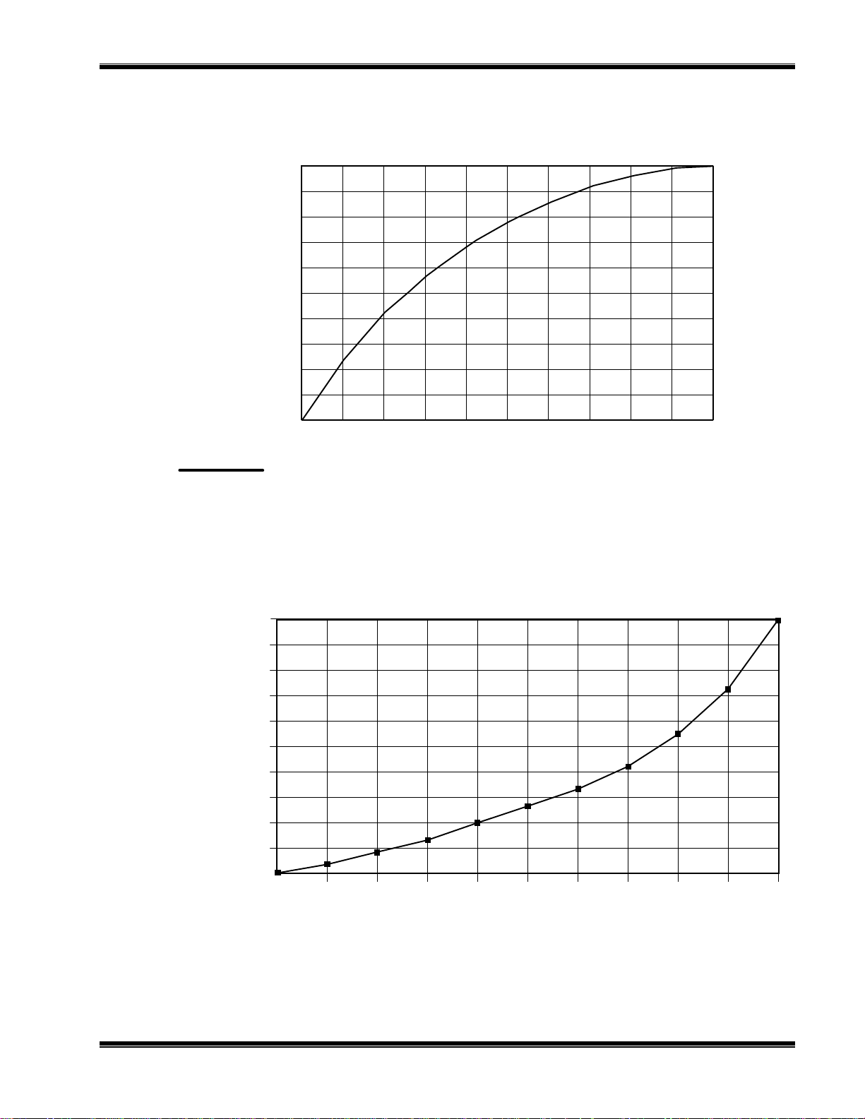
3.6 LINEARIZATION
The NDIR Analyzer Module can be operated in linear and non-linear mode.
Linearization can be toggled ON/OFF in
In the OFF position, linearization is disabled for all ranges, and the component of
interest is measured in percent of fullscale. In the ON position, measurement is in
engineering units: Either ppm or percent of concentration.
The NDIR Analyzer Module is linearized with the following fourth-order polynomial:
the Expert Controls
menu (see Figure 3-10).
Y = AO + A1X + A2X
2
+ A3X3 + A4X
4
Where:
X = the normalized non-linear input
AO, A1, A2, A3, A4 = linearization coefficients
Y = the normalized linear output
Linearization coefficients can be developed and stored for each range through the
Expert Controls
menu. The operating range is selected by entering RANGE = 1, 2, 3
or 4 in the Range Mode section that that menu.
Coefficients for each selected range are automatically used when the module is in
Linearization Mode. The user instructs the Analyzer Module as to which set of
coefficients are to be used for each range. Maximum dynamic range is 3:1.
When ordered, special linearization coefficients for non-standard fullscale ranges are
entered in the appropriate range(s) at the factory. If a range is not specified, the set of
coefficients will be for Range 4.
3-8
The operator may want the module to output measurement in engineering units (ppm).
This response is linear over the operating range. The following coefficients will make
no correction to the non-linear response, but will cause the NDIR Analyzer Module to
output gas measurement in engineering units:
A0 = 0.00000
A1 = 1.00000
A2 = 0.00000
A3 = 0.00000
A4 = 0.00000
To calculate linearization coefficients other than those installed at the factory, take a
June 1997 Rosemount Analytical 748332-DNGA 2000 Non-Dispersive Infrared Analyzer

S
TARTUP AND OPERATION
minimum of 11 data points. (A more accurate curve can be obtained as the user
approaches 21 data points. If urgent, a curve can be created with as few as four
points, but this is only a temporary fix. A more accurate curve should be created as
soon as possible.)
These data points can be obtained with an accurate gas divider or other flow mixing
device. Before calculating coefficients, the data must be normalized to ranges of 0 to
1 units for both percent and concentration readings. Then, the axis must be reversed
as illustrated in Figures 3-7 and 3-8. A multiple linear regression is then used to
calculate coefficients. (For example: If the range is 0 to 5000 ppm and readings are 0
to 100%, then divide all of the concentrations by 5000 and the readings by 100. Put
the normalized concentrations on the Y-axis and the normalized readings on the Xaxis.)
These data points can be entered into any program capable of computing a fourthorder polynomial curve. This curve will be the mirror image of the curve on the
Calibration and Data Sheet provided in the rear of this manual; however, the
linearization coefficients will be different. Use the coefficients calculated with the
curve in the polynomial shown on the previous page.
After taking the data points, the operator may determine coefficients for user-specific
gas by either using any program capable of calculating a fourth-order curve fit or
calling the factory to have the specific coefficients ca lculated.
When entering the operator-determined coefficients, note that the microprocessor only
recognizes five significant digits to the right of the decimal point (e.g., 0.12345).
3.7 ROUTINE OPERATION
Set the NDIR Analyzer Module for desired operating range. Zero and span the
module, and then supply sample gas to the SAMPLE INLET at the rear of the module.
The NDIR Analyzer Module will now automatically and continuously analyze the
sample stream.
As a check of instrument performance, the operator should keep a log of zero/span
status.
Maximum permissible interval between calibrations depends on the analytical
accuracy required. A frequency of once every 24 hours is recommended initially, and
that practice should be continued unless experience indicates that some other interval
is more appropriate.
Readout accuracy is directly proportional to change in barometric pressure (i.e., a
change in cell pressure of 7.6mm of mercury will result in a readout error of about 1%
of reading). Therefore, if barometric pressure changes significantly, a recheck of
calibration against a span gas is advised. Also, an optional Pressure Compensation
Board is available that electronically compensates.
748332-D Rosemount Analytical June 1997
NGA 2000 Non-Dispersive Infrared Analyzer
3-9
S
TARTUP AND OPERATION
The Analyzer Module will not allow the user to increase the upper limit of a range
beyond the "maximum range" software setting. To change the "maximum range"
value, select the following from the Main Menu: Technical Configuration Menu,
Service Menu, Manufacturing Data, Analyzer Manufacturing Data. Select Maximum
Range, and use the arrow keys to scroll the indicated value. The same applies for
"minimum range" setting.
Basic controls...
Main Menu
Expert controls and setup...
(Operational configuration)
Technical level configuration...
(Diagnostic and manufacturing/service)
Basic level security
(expert, technical)
Enter your security code with softkeys.
Security codes are set in the system setup
menu in the Technical level menus.
Press five characters when Security code
says READY. Press six to return to “READY”.
Security code: 54321
Basic controls
Measurement range number: 1
Range upper limit: 10 ppm
Range and functional control: LOCAL
Zero gas concentration: 0 ppm
Span gas concentration: 9.89 ppm
Ranges with valid calibration: 1&2
Calibration status: Ready
If it won’t calibrate...
Status: Ready
ZERO
Current measurement parameters
Measurement range number: 1
Range change control: Local
PARMS
Expert analyzer controls...
Auxiliary module controls...
System set up...
Analyzer module set up...
Auxiliary module set up...
Local I/O set up...
Measured Gas: CO2
Linearization mode: ON
Gas Measurement Setup: ON
Analyzer operational state: Normal
Analyzer alarm state: Normal
Alarms report: Failure
Expert controls and setup
SPAN
MORE
Technical configuration menu
System set up...
Service menus...
Diagnostic menus...
Other module diagnostic menus...
Listing of all modules...
Expert and Technical menus follow in
succeeding flow charts.
Current measurement parameters
Response time: 2.0 Secs
Sample flow: 1000 ml/min.
Sample pressure: 12.3 kPa
Case Temperature: 55.3°C
IGURE
F
3-10
Are you sure?
You must have zero gas flowing
through the analyzer.
This control does NOT control any
auto-cal. Module bound to this
analyzer!
If you are sure, press ZERO again now.
Press left arrow key when you are
done.
Calibration status: Ready
Error message for last zero: 24-08-94
Analyzer Zero
3-9. D
ISPLAY SCREENS
Are you sure?
You must have zero gas flowing
through the analyzer.
This control does NOT control any
auto-cal. Module bound to this
analyzer!
If you are sure, press SPAN again now.
Press left arrow key when you are
done.
Calibration status: Ready
Error message for last zero: 24-08-94
Analyzer Span
OF
(1
5)
Check that you are flowing the correct gas, and
If it won’t calibrate...
the gas concentration is what it is supposed to be.
Make sure that the reading is stable before
starting. If you have changed the range fullscale
value or any linearizer coefficients, or enabled or
disabled it, or done anything else that would affect
how it measures the gas, you may have made it
hard for the analyzer to calibrate. If so, manually
adjust the coefficients until the readings are close
to correct, and try again.
June 1997 Rosemount Analytical 748332-DNGA 2000 Non-Dispersive Infrared Analyzer

From MAIN MENU
⇒⇒⇒⇒
Expert controls and setup
Expert analyzer controls...
Auxiliary module controls...
System set up...
Analyzer Module set up...
Auxiliary Module set up...
Local I/O set up...
S
TARTUP AND OPERATION
Analyzer module set up...
and Auxiliary module set up... Outlined in the
next flow chart. Local I/O set up information is
included in the I/O Modules manual.
Measurement range number: 1
Range lower limit: 0 ppm
Range upper limit: 10 ppm
Linearizer: ON
Range and functional control: LOCAL
Zero/Span calibration...
Ranges with valid calibration: 1&2
Physical measurements...
CAL DATA
#1
Zero/Span diagnostic data
Date of last zero: 24-0894
Error message for last zero: 24-08-94
Error percentage for last zero: 5%
Raw signal at last zero: 500000
Last zero gas would read: -0.83 ppm
Date of last span: 24-08-94
Error message for last span: Great!
Error percentage for last span 5%
Raw signal at last span: 500000
The last span gas would read: 11.3 ppm
FACTORS
#3
Calibration Factors
Range 1 factors...
Range 2 factors...
Range 3 factors...
Range 4 factors...
Zero compensation factor: 1
Span compensation factor: 1
Expert controls
CAL
Auxiliary module controls
This screen selects any module with a
control screen. This includes any auto
calibration or sample module bound to
this analyzer.
Module Tag
Module Tag
Module Tag
Module Tag
Module Tag
Module Tag
Module Tag
Module Tag
Dependent on which auxiliary module is present
on the network. See I/O Modules manual.
#2
Zero offset: 500000
Span factor: 0.000015
Fullscale range at calibration: 10 ppm
Measurement range number: 1
Hardware zero offset: 0.0235 V
Raw measurement signal: 0.5250 V
Zero/Span Calibration
Measurement range number: 1
Zero gas concentration: 0 ppm
Span gas concentration: 9.89 ppm
Sample flow: 1000 ml/min.
Raw measurement signal: 0.3256 V
Ranges with valid calibration: 1&2
Status: Ready
Result...
Calibration adjustment limits: Enabled
FACTORS
Range 1 (2,3,4) Factors
System Set Up
Front panel control...
Display resolution...
Auxiliary lines...
See Platform manual for a flow chart
of these displays.
Physical Measurements
Sample flow: 1000 ml/min
Flow lower limit: 150 cc/min.
Flow upper limit: 250 cc/min.
Barometric pressure: 12.3 kPa
Case temperature: 54.3°C
See #1 on this flow chart
Range 1 (2,3,4) Factors
Manufacturer’s settings
HISTORY
Zero offset: 0
Span factor: 1000
Stored settings
Zero offset 500000
Span factor: 500000
IGURE
F
3-10. D
ISPLAY SCREENS
748332-D Rosemount Analytical June 1997
(2
OF
5)
NGA 2000 Non-Dispersive Infrared Analyzer
3-11
S
TARTUP AND OPERATION
From MAIN MENU
⇓
Expert controls and setup
Expert analyzer controls...
Auxiliary module controls...
System set up...
Analyzer Module set up...
Auxiliary Module set up...
Local I/O set up...
For Expert analyzer
controls, Auxiliary module
controls, and System set
up menus, see preceding
flow chard. Local I/O set
up information is included
in the I/O Modules manual.
Analyzer module set up
Calibration gas list...
Calibration param eters...
Gas measurement paramet er s...
Analyzer parameter list...
Physical measurement par ameters...
Displayed physical param eters...
Analyzer tag: IR
Auxiliary module set up
Select an auxiliary module for set up
Local I/O set up...
Module Tag
Module Tag
Module Tag
Module Tag
Module Tag
Module Tag
Module Tag
Dependent on which auxiliary module is
present on the network.
See I/O Modules manual.
Calibration gas list
Zero gas - range 1: 0 ppm
Span gas - range 1: 9.3 ppm
Zero gas - range 2: 0 ppm
Span gas - range 2: 19.3 ppm
Zero gas - range 3: 0 ppm
Span gas - range 3: 101.1 ppm
Zero gas - range 4: 0 ppm
Span gas - range 4: 247.1 ppm
Calibration...
#4
Calibration Parameters
Calibration adjustment limi ts: enabled
Calibration averaging time: 5 S ec s
Calibration failure alarm: Yes
Cal failure error allowed: 5%
Calibration time out: 60 Secs
Zero ranges: TOGETHER
Span ranges: SEPARATE
Measurement parameters
Linearization parameters...
Response time/delay param eters...
Range setting...
Units...
Linearization functions...
Zero/Span Calibration
See #2 in Figure 3-10
Linearization paramete rs
Range 1 linearizer: Enabled
if enabled, uses curve no.: 1
Range 2 linearizer: Enabled
if enabled, uses curve no.: 2
Range 3 linearizer: Enabled
if enabled, uses curve no.: 3
Range 4 linearizer: Enabled
if enabled, uses curve no.: 4
Case temperature for coefficient s: 45°C
Set coeffi c ients…
Response time/delay parameters
Range 1 t90 time: 10 Secs
Range 2 t90 time: 1 Secs
Range 3 t90 time: 1 Secs
Range 4 t90 time: 1 Secs
LON update rate: 1 per Sec
Output delay time: 0 Secs
Range Settings
Minimum range: 10 ppm
Maximum r ange: 5000 ppm
Range 1 lower limit: 0 ppm
Range 1 upper limit: 10 ppm
Range 2 lower limit: 0 ppm
Range 2 upper limit: 100 ppm
Range 3 lower limit: 0 ppm
Range 3 upper limit: 250 ppm
Range 4 lower limit: 0 ppm
Range 4 upper limit: 1000 ppm
Gas measurement units: ppm
Pressure measurement units: psig
Temperature measurement units: F
Variables are still s e nt as the basic SI unit.
Units
#5
Linearity coefficients
Curve 1 (2,3,4)
AO coeffi c ient: 1.34523E-4
A1 coefficient: 0.983751
A2 coefficient: 0.115751
A3 coefficient: 1.11575E-6
A4 coefficient: 7.3421E-12
Curve upper limit: 10 ppm
Curve over- r ange: 10%
Curve under-range: 5%
Status: Enabled
Polynomial set up
Range to be linearized: 1
Current span gas: 9.69 ppm
Calculated polynom ial order : 4
Gas values shown as: Percent
Gas concentrations...
Analyzer function: Ready
Gas concentrations
Gas value: 0
Raw reading: 0 ppm
Linearized values: 0 ppm
Gas value: 10
Raw reading: 11 ppm
Linearized values: 10 ppm
Point to be measured: Point 1
Analyzer function: Ready
Point 1
Point 2
Midpoint correction set up
Range 1 (2,3,4)
Correction: Disabled
Point being measured: Pt 1
Point 1 gas concentration: 100 ppm
Point 2 gas concentration: 120 ppm
Point 3 gas concentration: 150 ppm
Point 1 reading: 100 ppm
Point 2 reading: 120 ppm
Point 3 reading: 150 ppm
Span gas value: 100 ppm
Analyzer function: Ready
Analyzer Parameter List
Analyzer tag: IR-CO2
First line’s parameter: Flow
Second line’s parameter: Flow
Third line’s parameter: Flow
Fourth line’s parameter: Flow
Linearization parameters...
#6
Physical Measurements
Barometric pressure: 10.13 hPa
Sample flow: 500 cc /min.
Case temperature: 45°C
Detector temperature: 52°C
Pressure limits...
Temperature limits...
Displayed Parameters
First line’s parameter: Flow
Second line’s parameter: Flow
Third line’s parameter: Flow
Fourth line’s parameter: Flow
May be displayed on the appropriat e
line of the singl e analyzer display
screen.
Linearization functions
Polynomial set up...
Midpoint correction set up...
Use the polynomial set up t o gener ate a
linearizing pol y nomial from up to 20
gases.
Linearity coefficients
See #5 above
NEXT
Pressure Limits
Sample pressure upper limit: 15 kPa
Sample pressure lower limit: 10 kPa
Temperature Limits
Case upper limit: 60 C
Case lower limit: 20 C
Detector upper limit: 69 C
Detector lower limit: 55 C
Analyzer Parameter List
Primary Vari able Parameters
Control mode: LOCAL
Output delay time: 0 Secs
Range 1 upper limit: 10 ppm
Range 2 upper limit: 100 ppm
Range 3 upper limit: 250 ppm
Range 4 upper limit: 1000 ppm
Range 1 lower limit: 0 ppm
Range 2 lower limit: 0 ppm
Range 3 lower limit: 0 ppm
Range 4 lower limit: 0 ppm
Analyzer Parameter List
Primary Vari able Parameters
Range 1 t90 time: 10 Secs
Range 2 t90 time: 1 Secs
Range 3 t90 time: 1 Secs
Range 4 t90 time: 1 Secs
Linearizer on range 1: Enabl ed
Linearizer on range 2: Enabl ed
Linearizer on range 3: Enabl ed
Linearizer on range 4: Enabl ed
Analyzer Parameter List
Calibration Parameters
Calibration averaging time: 5 S ec s
Calibration failure alarm: Yes
Cal failure error allowed: 5%
Calibration time out: 60 Secs
Ranges zeroed: TOGETHER
Calibrate ranges: SEPARATE
Calibration adjustment limi ts: ENABLED
Analyzer Parameter List
Calibration Gases
Zero gas - range 1: 0 ppm
Zero gas - range 2: 0 ppm
Zero gas - range 3: 0 ppm
Zero gas - range 4: 0 ppm
Span gas - range 1: 9.3 ppm
Span gas - range 2: 19.3 ppm
Span gas - range 3: 101.1 ppm
Span gas - range 4: 247.1 ppm
IGURE
F
3-12
3-11. D
ISPLAY SCREENS
(3
OF
5)
June 1997 Rosemount Analytical 748332-DNGA 2000 Non-Dispersive Infrared Analyzer

From MAIN MENU
⇓
Technical configuration menu
System set up...
Service m enus...
Diagnostic menus...
Other module diagnostic menus...
Listing of all modules...
For Diagnostic menus,
Other module diagnostic
menus, and Listing of all
modules, see Figure 3-11.
System Set Up
Main display configuration...
Front panel control...
Date and time...
Module binding...
System Reset...
Security codes...
System tag: Rosemount
Main display configuration, Front
panel control, and Date and time
displays can be found in the Platform
manual.
Module Binding
Analyzer module selec ted: IR-CO2
Select modules...
Proposed bind:
View bindings...
Bind selections!
Unbind everythi ng!
System Reset
Are you sure?
Re-initializing will destroy all the binds!!!
System reset!
Re-initialize network!
Record security codes
Basic level secur ity: Enabled
Expert level security: Enabled
Technical level security: Enabled
Record basic level security code...
Record expert level security code...
Record technical level security code...
Manufacturing data
Control module data. ..
Analyzer module data...
Module Tag
Module Tag
Module Tag
Module Tag
Module Tag
Module Tag
Module Tag
Module Tag
Select IO modules
Select the modules you wish to bind to the
current analyzer.
Module Tag
Module Tag
Module Tag
Module Tag
Module Tag
Module Tag
Module Tag
Module Tag
Modules Bound
Analyzer module selec ted: IR-CO2
Auxiliary module: Auto 1023
Auxiliary module: Acal 2322
Auxiliary module: HART 1092
Auxiliary module: None
Auxiliary module None
Auxiliary module: None
Proposed new bind:
#7
Record basic level security codes
(expert, technical)
Press the softkeys in any order to define the
code. The actual code is represented by the
order in which they are pressed, and shown
numerically below. Press the left arrow key
when you are done.
Actual code number: 54321
Control Unit Manufacturing Data
Control unit serial number: 800002356
Manufacturing date code: 12-08-93
Hardware revision number: 1.00
Software revision number: 1.09
Revision notes...
User tag number: PV1c
Analyzer Manufacturing Data
Analyzer module s/n: 900189342
Manufacturing data code: 17-08-93
Bench configurati on c ode: 17
Hardware revision number: 1.13
Software revision number: 1.03
Minimum range: 10 ppm
Maximum r ange: 5000 ppm
Measured gas: CO2
User tag number: IR-CO2
S
TARTUP AND OPERATION
IGURE
F
Service Menus
Manufacturing data. ..
Service history...
In maintenance since: N/A
Record security codes...
3-12. D
ISPLAY SCREENS
Service History
Control module data. ..
Analyzer module data...
Module Tag
Module Tag
Module Tag
Module Tag
Module Tag
Module Tag
Module Tag
Module Tag
Record security codes
Basic level secur ity: Enabled
Expert level security: Enabled
Technical level security: Enabled
Record basic level security code...
Record expert level security code...
Record technical level security code...
See #7 above
OF
(4
5)
STORE
RESET
Store historical data
Are you sure?
STORE will copy current diagnostic data into
the historical ("was") variables, overwriting
what is currently there.
Reset
Are you sure?
RESET will erase ALL configuration and
manufacturing data, including serial
numbers.
Control Module Service History
Manufacturing date: 12-08-93
In service date: 01-23-94
Last service date: 01-23-94
List notes...
Add service date!
Analyzer module Service History
Manufacturing date: 17-08-93
In service date: 21-06-94
Last zero calibration date: 24-08-94
Last span calibration date: 24- 08- 94
Last service date: 21-06-94
List notes...
Add service date!
This function not applicable.
Slot position: 1
I/O module
748332-D Rosemount Analytical June 1997
NGA 2000 Non-Dispersive Infrared Analyzer
3-13

S
TARTUP AND OPERATION
From MAIN MENU
Technical configuration menu
System set up...
Service m enus...
Diagnostic menus...
Other module diagnostic menus...
Listing of all modules...
Diagnostic menus
Control module diagnostics...
Analyzer module di agnost ics...
Module Tag
Module Tag
Module Tag
Module Tag
Module Tag
Module Tag
Module Tag
Module Tag
⇓
For Service set up and
Service m enus, see
preceding flow charts.
Control Unit Diagnostics
See Platform manual.
#8
Analyzer Diagnostics
Power supply voltages...
Primary variable parameters. ..
Physical measurement s...
Temperature control parameters...
Miscellaneous control parameters...
Barometric pressure param eters...
Software diagnostics...
Analyzer diagnostics
Power supply voltages
+15V analog is: 14.98V
+15V analog was: 14.92V
-15V analog is: -14.85V
-15V analog was: -14.92V
+5V digital is: 5.02V
+5V digital was: 4.98V
+24V power is: 2.38V
+24V power was: 2.42V
+12V analog is: 11.88V
+12V analog was: 12.0V
Primary variable parameters
Raw measurement signal: 0.3258
Signal gain setting: 4%
Oscillator tune: 85%
Chopper speed: 5 Hz
Source current: 1.212 A
Modulation check.. .
Percent modulati on: 20%
Calibration time out: 60 Secs
Calibration f ac tors...
Pk-pk noise: 0 ppm
Modulation check
Measurement range number: 1
Detector signal: 7.0
Signal gain setting: 4%
Status Ready
Instructions: Flow zero
Then: Watt
Percent modulati on: 20%
(updated only at the end of this test)
Calibration Factors
See #3 in Figure 3-12
HISTORY
Other module diagnostics
This screen reserved for other modules
if present.
Module Tag
Module Tag
Module Tag
Module Tag
Module Tag
Module Tag
Module Tag
Module Tag
Listing of all modules
Lists all modules detected on the
network.
Jumps to the module’s diagnostic
screen.
Module Tag
Module Tag
Module Tag
Module Tag
Module Tag
Module Tag
For I/O Module diagnostics,
see I/O Modules manual
Analyzer Diagnostics
See #8 above.
Physical measurements
See #6 in Figure 3-12
Temperature control
Fan lower setpoint: 60°C
Fan upper setpoint : 20°C
Minimum fan duty cycle: 30%
Case temperature: 45°C
Detector setpoint: 62°C
Detector P gain: 32.52
Detector I gain: 1.34
Detector bias: 283°C
Detector temperature: 62°C
Miscellaneous control parameters
Fan current: 35 mA
Fan duty cycle: 50%
Heater current: 1.7A
Heater duty cycle: 50%
Source current pot setting: 50%
Actual source current: 1. 212A
Alarm messages val id for: FAILURE
Barometric pressure parameters
Pressure transducer: Present
Barometric pres. Compensation: Enabled
Measured pressure: 12.3 kPa
Transducer offset: 1013 hP a
Transducer slope: 1.0
Transducer PGA gain: 1.0
Software diagnostics
Last message: No error
And: No error
And: No error
And: No error
And: No error
And: No error
And: No error
And: No error
Edit to reset: Report
Software error code (1 = no error): 1
Primary variable parameters
Signal gain settings: 4%
Oscillator tune: 85%
Source current: 1.212 A
Percent modulati on: 85%
IGURE
F
3-14
3-13. D
ISPLAY SCREENS
(5
OF
5)
June 1997 Rosemount Analytical 748332-DNGA 2000 Non-Dispersive Infrared Analyzer

M
AINTENANCE AND TROUBLESHOOTING
4
WARNING: ELECTRICAL SHOCK HAZARD
Servicing requires access to live parts which can cause death or serious injury.
Refer servicing to qualified personnel.
4.1 OVERVIEW
NDIR Analyzer Module components that may require cleaning or replacement include:
all printed circuit boards
•
power fuse
•
the module fan
•
the chopper motor
•
the source
•
the detector
•
flow sensor
•
case temperature sensor
•
Analysis cells and optical components
•
RTD - detector temp. controller
•
thermal fuse
•
The only components that may require adjustment are the oscillator tune and shutter
balance adjustments. These are factory-set, and should be adjusted only in the
following cases:
if the operator has changed sources, oscillator board or detector
•
if the operator disassembles the bench to any degree.
•
Also available for maintenance adjustment through the Front Panel display and
keypad are the source current, preamplifier gain (referred to as Signal Gain on the
sub-menu) and the modulation check.
748332-D Rosemount Analytical June 1997
NGA 2000 Non-Dispersive Infrared Analyzer
4-1

M
AINTENANCE AND TROUBLESHOOTING
4.2 PCB REPLACEMENT
Refer to Figure 4-1 for locations of the Signal, Micro, Power Supply, Oscillator and
optional Pressure Compensation boards.
All PCBs, except the Oscillator Board and the LON Power Board, are secured to a
side of the analyzer module that folds out while interconnect wiring is still in place.
Remove the securing screws and fold out the entire panel.
TOP VIEW
IGURE
F
SIDE VIEW
4-1. P
Power Supply
Board
RINTED CIRCUIT BOARD FOLD-OUT PANEL VIEWS
Pressure
Compensation Board
Micro Board Signal Board
To remove a particular board on the fold-out panel, label and unplug all interconnect
wiring, and remove securing hardware. (See Figure 4-1.) Do the reverse to install a
new board. Use caution when installing connectors by observing correct position
(polarity) and alignment of pins.
4.3 POWER FUSE REPLACEMENT
Remove power to the Analyzer Module prior to fuse replacement. To replace the
Power Fuse, view the front panel of the Analyzer Module, as shown in Figure 2-4, and
push and turn the fuseholder cap 1/4 turn counterclockwise. Remove and replace the
fuse as required.
4.4 MODULE FAN REPLACEMENT
The Analyzer Module fan assembly is disassembled as shown in Figure 4-2. Before
doing so, though, the entire optical bench must be removed. See Figure 4-4.
4-2
June 1997 Rosemount Analytical 748332-DNGA 2000 Non-Dispersive Infrared Analyzer

Air
Flow
M
AINTENANCE AND TROUBLESHOOTING
IGURE
F
4-2. M
ODULE FAN ASSEMBLY
4.5 CHOPPER MOTOR REPLACEMENT
See Figure 4-3 for a breakdown of the Motor/Source Assembly. The entire optical
bench must be removed to perform this replacement.
4.6 SOURCE REPLACEMENT
See Figure 4-3 for a breakdown of the Motor/Source Assembly. The entire optical
bench must be removed to perform this replacement.
4.7 DETECTOR REMOVAL
See Figures 4-4 and 4-6 for breakdowns of the optical bench. The entire optical bench
must be removed in order to perform this disassembly.
4.8 FLOW SENSOR REPLACEMENT
See Figure 4-4 for Flow Sensor location. To replace Flow Sensor, remove all
connecting hardware and undo connections to the sample line.
748332-D Rosemount Analytical June 1997
NGA 2000 Non-Dispersive Infrared Analyzer
4-3

M
AINTENANCE AND TROUBLESHOOTING
IGURE
F
Source Assemblies
(see detail below)
Screw
Lock Washer
Insulator
4-3. M
OTOR/SOURCE ASSEMBLY
Source
Housing Assembly
Ref - Source
Assemblies
Source Case
Insulator
Ref - Housing
Assembly
Motor Plate
Motor
Chopper
Blade
O-Ring
Retaining
Ring
Screw
Nylon
Washer
Source Buffer
Dual Cap
Assembly
Screen Filter
(optional)
Source Gasket
4.9 CASE TEMPERATURE SENSOR REPLACEMENT
Case Temperature Sensor is attached to the motor source assembly. To replace this
sensor, cut the Ty-Rap binder and disconnect the sensor connector. Reverse these
instructions by reconnecting the new sensor and attaching with a new Ty-Rap.
4.10 THERMAL FUSE REPLACEMENT
Disassemble and reassemble the Detector block according to Figure 4-6 to replace
the Detector Thermal Fuse.
4.11 OSCILLATOR TUNE/SOURCE BALANCE SHUTTER
ADJUSTMENT
The Analyzer Module is calibrated, tuned and balanced at the factory. If the diagnostic
values for oscillator tune and detector signals are within ±5 % of the factory settings
(see Figure 3-13, in Primary Variable Parameters and Modulation Check menus), no
adjustment is necessary. If not, see Figure 4-4 and 4-5 for Oscillator T une and Source
Balance Shutter adjustments, and do the following:
4-4
June 1997 Rosemount Analytical 748332-DNGA 2000 Non-Dispersive Infrared Analyzer

M
AINTENANCE AND TROUBLESHOOTING
1. Open Platform front panel, if present.
CAUTION: HAND INJURY HAZARD
Do not place hands or fingers in Platform front handles when the front panel is
open. Dropping front panel while hand or fingers are inside either handle can
cause serious injury.
2. Open Analyzer Module front panel
3. Access the oscillator tune value in the Primary Variable Parameters menu.
4. Adjust oscillator tune knob to its maximum setting and then turn it
counterclockwise to 80 % of that maximum setting.
5. Access the detector signal value in the Modulation Check menu.
6. Flow zero gas (nitrogen) through the sample cell until the display reading
stabilizes.
CAUTION: DELICATE COMPONENTS
The shutter is a delicate component with only a six-degree rotation. Take care
when making the required adjustments.
7. Using an appropriate screwdriver that will fit through the Source Balance
Adjustment Screw Holes (see Figure 4-5), rotate the sample shutter adjust screw
until a minimum reading on the display is obtained. (A typical reading is 0.2
through 0.5.)
8. Add 0.5 V to the value obtained in Step 7 by adjusting the sample shutter adjust
screw clockwise. (If this reading exceeds 1.2 V, then a cell cleaning is necessary;
see Section 4.12.)
9. Rotate the shutter adjust screw clockwise until the display reads the value obtained
in Step 8.
10. Reassemble the Analyzer Module and, if appropriate, the Platform.
748332-D Rosemount Analytical June 1997
NGA 2000 Non-Dispersive Infrared Analyzer
4-5

M
AINTENANCE AND TROUBLESHOOTING
Oscillator Tune
Adjust
Detector Assembly
Motor/Source
Assembly
Shutter Shaft
Power
Transistor/Heatsink
IGURE
F
4-6
4-4. C
ELL
, PCB A
Flow Sensor
SSEMBLY (EXPLODED VIEW
June 1997 Rosemount Analytical 748332-DNGA 2000 Non-Dispersive Infrared Analyzer
)
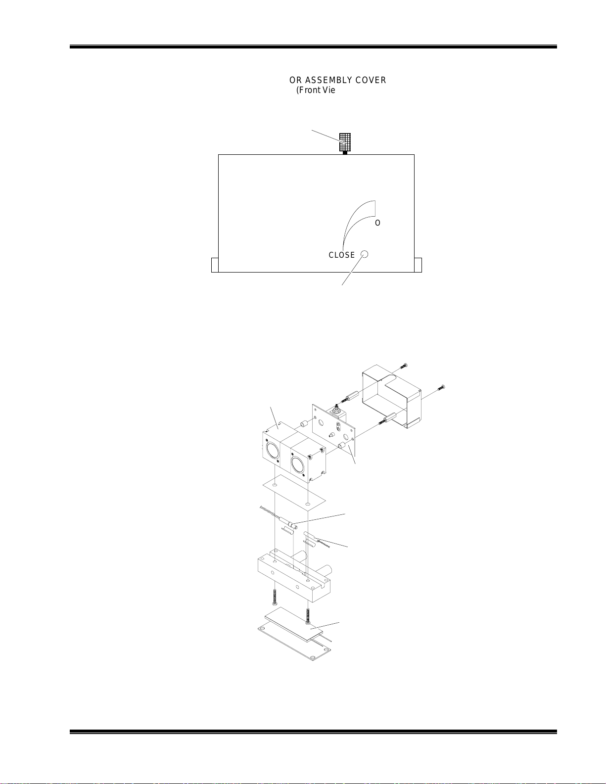
DETECTOR ASSEMBLY COVER
(Front View)
M
AINTENANCE AND TROUBLESHOOTING
IGURE
F
4-5. O
Oscillator Tune Adjustment
SCILLATOR TUNE
SHUTTER
Sample
OPEN
CLOSE
Source Balance Shutter
Adjustment Screw Hole
OURCE BALANCE SHUTTER ADJUSTMENTS
, S
Detector
IGURE
F
748332-D Rosemount Analytical June 1997
4-6. D
ETECTOR BLOCK (EXPLODED VIEW
Oscillator Board
Resistive Temperature
Detector
Thermal Fuse
Detector Heater
)
NGA 2000 Non-Dispersive Infrared Analyzer
4-7

M
AINTENANCE AND TROUBLESHOOTING
4.12 CLEANING CELLS
1. When zero gas is introduced in the SAMPLE IN inlet and the Detector signal is
greater 1.2V, the cells and windows require cleaning. To do this, follow this
procedure:
2. See Figure 4-7 to identify which detail drawing best matches the configuration in
question.
3. Fold out the PCB panel.
4. Disassemble the optical bench according to Figure 4-4 and the cells according to
Figure 4-7.
5. Rinse the cell with acetone. If this does not remove all foreign matter, use a soft
brush. Do not use an y metallic o bject in side the ce ll be cause it will scratch th e gold
plating. Loss of gold plating may require cell replacement.
6. After all matter has been remo ved, rinse the cell with distilled water and allow to air
dry. Do not use towels.
7. Inspect the cell inside by holding it up to a bright light. If particles are seen, repeat
Steps 5 and 6 as often as necessary.
8. After cleaning cell, examine O-rings at the source, detector and end caps. If
damaged, replace with new O-rings.
9. Remove any contaminants from windows with a lint-free cloth soaked in acetone.
Do not use alcohol or other solvents. Allow to air dry.
10. Reverse disassemble instructions to reassemble the unit.
11. Perform a leak check.
12. Replace desiccant if required. (See Section 4.13.)
13. After cleaning cells, the Analyzer Module must be optically aligned if the diagnostic
values for oscillator tune and detector signals are not within ±5% of the factory
settings (see Figure 3-13, in Primary Variable Parameters and Modulation Check
menus). If they are not within that range, follow Steps 7 through 10 of Section 4.11.
4-8
June 1997 Rosemount Analytical 748332-DNGA 2000 Non-Dispersive Infrared Analyzer
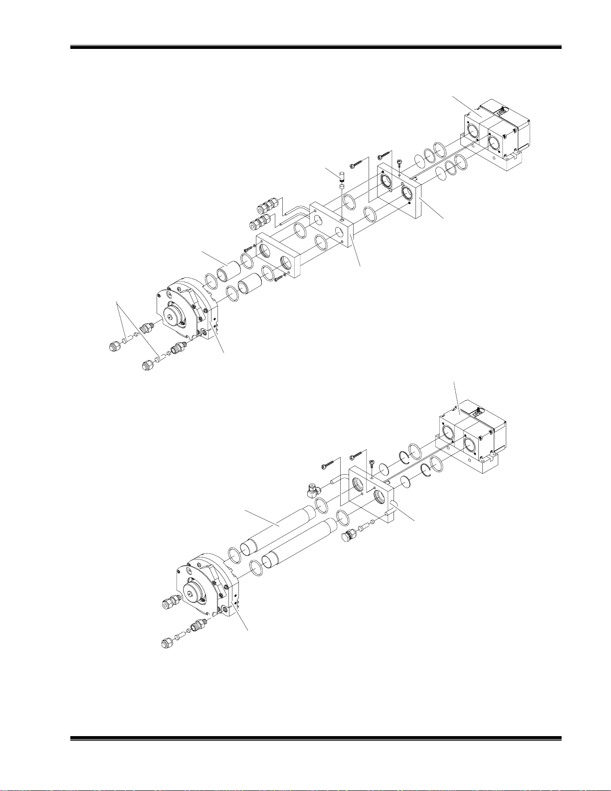
SHORT PATH CELLS
4mm TO 2.5 INCHES
Spacer
Desiccant Holder
M
AINTENANCE AND TROUBLESHOOTING
Detector
Assembly
Shutter Block
Assembly
Desiccant
Holders
LONG PATH CELLS
Motor/Source
Assembly
Sample Cell
Sample Cell
Detector
Assembly
Shutter Block
Assembly
Motor/Source
Assembly
IGURE
F
748332-D Rosemount Analytical June 1997
4.7. C
ELL DISASSEMBLY
NGA 2000 Non-Dispersive Infrared Analyzer
4-9

M
AINTENANCE AND TROUBLESHOOTING
4.13 CELL DESICCANT
The reference cell may use a flowing reference. If so, desiccant is required. A
desiccant holder is used on the inlet and outlets to keep moisture from entering the
reference cell (see Figure 4-7). The desiccant should be replaced each time the cell is
opened, refer to Table 4-1. Before inserting desiccant, purge cell with dry inert gas
(i.e., N2).
GAS DESICCANT PART NUMBER
CO
2
CO Mg (C104)
H20Mg (C10
SOS Mg (C104)
CH
4
Hexane Mg (C104)
CO + CO
2
Cardoxide + Mg (C104)
Cardoxide 096218
096217
096217
096217
096217
096217
096217/09621
4)2
Mg (C104)
2
2
2
2
2
ABLE
T
4-1. C
ELL DESICCANT
4.14 MODULATION CHECK
The modulation check is a measure of the energy absorption capacity of a gas
mixture, where total absorbency is 100% modulation and zero absorbency is 0%
modulation. The modulation check can be used as a tool for tracking the sensitivity of
the Analyzer Module and for discovering potential detector/source problems.
To perform a modulation check, do the following:
1. Access the Primary Variable Parameters menu (see Figure 3-13).
2. Select Modulation Check.
3. Follow the
Instructions
a. Flow zero gas, press START softkey and wait.
b. Flow span gas when prompted, press START softkey and wait.
4. When the
Instructions
check is finished.
5. Note the value on the
Find the Percent Modulation value on the Data Sheet in the rear of this manual. Some
standard Analyzer Modules will not have a value. If a value is present, compare this to
the new value.
and
line commands, which are the following:
Then
line again prompts the user to flow zero gas, the modulation
Percent Modulation
line.
4-10
If 100% span gas was used during the modulation check, the new value should be
within ±10% of value on the Data Sheet. If it is out of this range, call the factory for
further interpretation. If modulation checks are used for trending, variance from check
to check should not exceed ±20% per month.
June 1997 Rosemount Analytical 748332-DNGA 2000 Non-Dispersive Infrared Analyzer
R
EPLACEMENT PARTS
5
WARNING: PARTS INTEGRITY
Tampering with or unauthorized substitution of components may adversely
affect safety of this product. Use only factory-approved components for repair.
5.1 REPLACEMENT PARTS
While the following sections list parts which are common to all NDIR Analyzer
Modules, the
specific to an individual application. The configuration number is on the Data Sheet in
the rear of this manual.
NL623998 Oscillator Board
configuration number
is required when ordering parts which are
NL657466 LON/Power Board
NL655729 Detector Heater
NL622917 Temperature Sensor, Detector
NL898733 Thermal Fuse with Q Pad
NL902931 Flow Sensor
NL655943 Case Temperature Sensor
NL655630 Power Supply Board
NL655670 Pressure Compensation Board
NL655588 Computer Analysis Board
NL655610 Signal Board
NL655893 Fan
NL655891 Chopper Motor
NL655925 Source (Matched Pair)
748332-D Rosemount Analytical June 1997
NGA 2000 Non-Dispersive Infrared Analyzer
5-1

R
EPLACEMENT PARTS
N
OTES
5-2
June 1997 Rosemount Analytical 748332-DNGA 2000 Non-Dispersive Infrared Analyzer

A
PPENDIX
A. NDIR I
DENTIFICATION MATRIX
A
Each analyzer is configured per the customer sales order. Below is the NDIR sales matrix
which lists the various configurations available.
To identify the configuration of an analyzer, locate the analyzer name-rating plate. The 12position sales matrix identifier number appears on the analyzer name-rating plate.
I SINGLE CHANNEL NON-DISPERSIVE INFRARED ANALYZER MODULE
Code Language
A English
X Special
Code Configuration Identifier
A09, A10, A12, A20, B22, B23, B2B30, B36, B38
A06, A07, A08, A11, B21, B24, B26, B76, F63
A16, A28, B19, B25, B27, C31, C37, C39, D41, D44
A14, A15, B46, E54, F64, F65, F66, F67, H73
E56, H74, H75, J83, H84, J85, J88
L99 SPECIAL Extended Length
S99 SPECIAL Standard Length
Code
ZOO No Selection
Code Linearized Non-Standard Range Selection
A Four Standard Ranges
B One Non-Standard Range
C Two Non-Standard Ranges
D Three Non-Standard Ranges
F Four Non-Standard Ranges
X Special
Code
ZNo
IAA10Z00AZZ Example
748332-D Rosemount Analytical June 1997
Selection
Code
Z No Selection
NGA 2000 Non-Dispersive Infrared Analyzer
A-1

A
PPENDIX
N
OTES
A. NDIR I
DENTIFICATION MATRIX
A-2
June 1997 Rosemount Analytical 748332-DNGA 2000 Non-Dispersive Infrared Analyzer

ENERAL PRECAUTIONS FOR HANDLING AND
G
TORING HIGH PRESSURE GAS CYLINDERS
S
Edited from selected paragraphs of the Compressed
Gas Association's "Handbook of Compressed Gases"
published in 1981
Compressed Gas Association
1235 Jefferson Davis Highway
Arlington, Virginia 22202
Used by Permission
1. Never drop cylinders or permit them to strike each other violently.
2. Cylinders may be stored in the open, but in such cases, should be protected against
extremes of weather and, to prevent rusting, from the dampness of the ground. Cylinders
should be stored in the shade when located in areas where extreme temperatures are
prevalent.
3. The valve protection cap should be left on each cylinder until it has been secured
against a wall or bench, or placed in a cylinder stand, and is ready to be used.
4. Avoid dragging, rolling, or sliding cylinders, even for a short distance; they should be
moved by using a suitable hand-truck.
5. Never tamper with safety devices in valves or cylinders.
6. Do not store full and empty cylinders together. Serious suckback can occur when an
empty cylinder is attached to a pressurized system.
7. No part of cylinder should be subjected to a temperature higher than 125°F (52°C). A
flame should never be permitted to come in contact with any part of a compressed gas
cylinder.
8. Do not place cylinders where they may become part of an electric circuit. When electric
arc welding, precautions must be taken to prevent striking an arc against the cylinder.
4125 E
AST LA PALMA AVENUE
Rosemount Analytical Inc.
• A
J
, C
NAHEIM
ULY
ALIFORNIA
1997 • 748525-C • P
92807-1802 • 714-986-7600 • FAX 714-577-8006
RINTED IN
USA

(blank)

ARRANTY
W
Goods and part(s) (excluding consumables) manufactured by Seller are warranted to be free from
defects in workmanship and material under normal use and service for a period of twelve (12)
months from the date of shipment by Seller. Consumables, glass electrodes, membranes, liquid
junctions, electrolyte, o-rings, etc., are warranted to be free from defects in workmanship and
material under normal use and service for a period of ninety (90) days from date of shipment by
Seller. Goods, part(s) and consumables proven by Seller to be defective in workmanship and/or
material shall be replaced or repaired, free of charge, F.O.B. Seller's factory provided that the goods,
part(s) or consumables are returned to Seller's designated factory, transportation charges prepaid,
within the twelve (12) month period of warranty in the case of goods and part(s), and in the case of
consumables, within the ninety (90) day period of warranty. This warranty shall be in effect for
replacement or repaired goods, part(s) and the remaining portion of the ninety (90) day warranty in
the case of consumables. A defect in goods, part(s) and consumables of the commercial unit shall
not operate to condemn such commercial unit when such goods, part(s) and consumables are
capable of being renewed, repaired or replaced.
The Seller shall not be liable to the Buyer, or to any other person, for the loss or damage directly or
indirectly, arising from the use of the equipment or goods, from breach of any warranty, or from any
other cause. All other warranties, expressed or implied are hereby excluded.
IN CONSIDERATION OF THE HEREIN STATED PURCHASE PRICE OF THE GOODS, SELLER
GRANTS ONLY THE ABOVE STATED EXPRESS WARRANTY. NO OTHER W ARRANTIES ARE
GRANTED INCLUDING, BUT NOT LIMITED TO, EXPRESS AND IMPLIED WARRANTIES OR
MERCHANTABILITY AND FITNESS FOR A PARTICULAR PURPOSE.
Limitations of Remedy. SELLER SHALL NOT BE LIABLE FOR DAMAGES CAUSED BY DELAY IN
PERFORMANCE. THE SOLE AND EXCLUSIVE REMEDY FOR BREACH OF WARRANTY SHALL
BE LIMITED TO REPAIR OR REPLACEMENT UNDER THE STANDARD W ARRANTY CLAUSE. IN
NO CASE, REGARDLESS OF THE FORM OF THE CAUSE OF ACTION, SHALL SELLER'S
LIABILITY EXCEED THE PRICE TO BUYER OF THE SPECIFIC GOODS MANUFACTURED BY
SELLER GIVING RISE TO THE CAUSE OF ACTION. BUYER AGREES THAT IN NO EVENT
SHALL SELLER'S LIABILITY EXTEND TO INCLUDE INCIDENTAL OR CONSEQUENTIAL
DAMAGES. CONSEQUENTIAL DAMAGES SHALL INCLUDE, BUT ARE NOT LIMITED TO, LOSS
OF ANTICIPATED PROFITS, LOSS OF USE, LOSS OF REVENUE, COST OF CAPITAL AND
DAMAGE OR LOSS OF OTHER PROPERTY OR EQUIPMENT. IN NO EVENT SHALL SELLER BE
OBLIGATED TO INDEMNIFY BUYER IN ANY MANNER NOR SHALL SELLER BE LIABLE FOR
PROPERTY DAMAGE AND/OR THIRD PARTY CLAIMS COVERED BY UMBRELLA INSURANCE
AND/OR INDEMNITY COVERAGE PROVIDED TO BUYER, ITS ASSIGNS, AND EACH
SUCCESSOR INTEREST TO THE GOODS PROVIDED HEREUNDER.
Force Majeure. Seller shall not be liable for failure to perform due to labor strikes or acts beyond
Seller's direct control.
Rosemount Analytical
4125 E
AST LA PALMA AVENUE
Rosemount Analytical Inc.
• A
F
EBRUARY 1997 • 7485189-C • PRINTED IN USA
NAHEIM
, C
ALIFORNIA
92807-1802 • 714-986-7600 • FAX 714-577-8006

(blank)

IELD SERVICE AND REPAIR FACILITIES
F
Field service and repair facilities are located worldwide.
U.S.A.
To obtain field service on-site or assistance with a service problem, contact (24 hours, 7
days a week):
National Response Center
1-800-654-7768
INTERNATIONAL
Contact your local Rosemount Sales and Service office for service support.
FACTORY
For order administration, replacement Parts, application assistance, on-site or factory repair,
service or maintenance contract information, contact:
Rosemount Analytical Inc.
Process Analytical Division
Customer Service Center
1-800-433-6076
RETURNING PARTS TO THE FACTORY
Before returning parts, contact the Customer Service Center and request a Returned
Materials Authorization (RMA) number. Please have the following information when you call:
Model Number, Serial Number, and Purchase Order Number or Sales Order Number.
Prior authorization by the factory must be obtained before returned materials will be
accepted. Unauthorized returns will be returned to the sende r, f re ight collect.
When return ing any product or compon ent that has been expo sed to a toxic, co rrosive or
other hazardous material or used in such a hazardous environment, the user must attach an
appropriate Material Safety Data Sheet (M.S.D.S.) or a written certification that the material
has been decontaminated, disinfected and/or detoxified.
Return to:
Rosemount Analytical Inc.
4125 East La Palma Avenue
Anaheim, California 92807-1802
4125 E
AST LA PALMA AVENUE
Rosemount Analytical Inc.
• A
ULY 1997 • 748190-G • PRINTED IN USA
J
NAHEIM
, C
ALIFORNIA
92807-1802 • 714-986-7600 • FAX 714-577-8006

(blank)
 Loading...