

Page 1

NGA 2000
AST
F
D
ESPONSE PARAMAGNETIC
R
ETECTOR
NALYZER
A
ODULE
M
Rosemount Analytical
748362-B
Page 2

N
OTICE
The information contained in this document is subject to change without notice.
Viton-A® is a registered trademark of E.I. duPont de Nemours & Co.
Manual Part Number 748362-B
December 1998
Printed in U.S.A.
Rosemount Analytical Inc.
4125 East La Palma Avenue
Anaheim, California 92807-1802
Page 3

ONTENTS
C
PREFACE
PURPOSE/SAFETY SUMMARY........................................................................P-1
GLOSSARY ......................................................................................................P-5
SPECIFICATIONS..............................................................................................P-7
SPECIFICATIONS - SAMPLE............................................................................P-8
SPECIFICATIONS - PHYSICAL.........................................................................P-8
CUSTOMER SERVICE, TECHNICAL ASSISTANCE AND FIELD SERVICE....P-9
RETURNING PARTS TO THE FACTORY.........................................................P-9
TRAINING ......................................................................................................P-9
DOCUMENTATION............................................................................................P-9
COMPLIANCES .................................................................................................P-10
S
ECTION
1.1 OVERVIEW..............................................................................................1-1
1.2 TYPICAL APPLICATIONS .......................................................................1-1
1.3 THEORY OF TECHNOLOGY...................................................................1-1
1.4 FEATURES ..............................................................................................1-2
S
ECTION
2.1 UNPACKING............................................................................................2-1
2.2 ASSEMBLY..............................................................................................2-1
2.3 LOCATION...............................................................................................2-2
2.4 GASES.....................................................................................................2-2
2.5 ELECTRICAL CONNECTIONS................................................................2-5
1. I
2. I
2.4.1 Requirements..............................................................................2-2
2.4.2 Connections................................................................................2-5
2.4.3 Leak Test....................................................................................2-5
NTRODUCTION
NSTALLATION
748362-B Rosemount Analytical December 1998
NGA 2000 Fast Response Paramagnetic Detector
i
Page 4

C
ONTENTS
SECTION 3. STARTUP AND OPERATION
3.1 OVERVIEW ............................................................................................. 3-1
3.2 DISPLAYS ............................................................................................... 3-1
S
ECTION
3.3 RUN MODE DISPLAY ............................................................................. 3-1
3.4 MENU DISPLAYS.................................................................................... 3-2
3.5 HELP DISPLAYS..................................................................................... 3-3
3.6 STARTUP PROCEDURE ........................................................................ 3-5
3.7 BINDING.................................................................................................. 3-6
3.8 CALIBRATION......................................................................................... 3-6
3.9 BACKGROUND GAS COMPENSATION................................................. 3-7
3. S
TARTUP AND OPERATION (CONTINUED
)
SECTION 4. MAINTENANCE AND TROUBLESHOOTING
4.1 OVERVIEW ............................................................................................. 4-1
4.2 PRINTED CIRCUIT BOARD REPLACEMENT........................................ 4-1
4.3 MODULE FAN REPLACEMENT.............................................................. 4-3
4.4 THERMAL FUSE REPLACEMENT ......................................................... 4-3
4.5 FLOW SENSOR REPLACEMENT .......................................................... 4-3
4.6 POWER FUSE REPLACEMENT............................................................. 4-3
SECTION 5. REPLACEMENT PARTS
5.1 REPLACEMENT PARTS......................................................................... 5-1
APPENDIX A. FR-PMD IDENTIFICATION MATRIX
ENERAL PRECAUTIONS FOR HANDLING AND STORING HIGH PRESSURE CYLINDERS
G
ARRANTY
W
IELD SERVICE AND REPAIR FACILITIES
F
ii
December 1998 Rosemount Analytical 748362-BNGA 2000 Fast Response Paramagnetic Detector
Page 5

FIGURES
1-1 Spherical Body in Non-Uniform Magnetic Field........................................1-2
1-2 Paramagnetic Detector Technology.........................................................1-3
1-3 Fast Response Paramagnetic Detector Analyzer Module - Top View......1-4
2-1 Analyzer Module Installation into Instrument Platform .............................2-1
2-2 FR-PMD Front Panel Connections...........................................................2-4
2-3 FR-PMD Back Panel Connections...........................................................2-4
2-4 Interconnection of Typical Gas Manifold to FR-PMD Analyzer Module....2-5
2-5 FR-PMD Wiring Diagram..........................................................................2-6
2-6 Outline and Mounting Dimensions............................................................2-7
3-1 Run Mode Display....................................................................................3-3
3-2 Main Menu Display...................................................................................3-3
3-3 Basic Controls Menu................................................................................3-4
3-4 Expert Controls and Setup Menu.............................................................3-4
3-5 Technical Level Configuration Menu........................................................3-4
3-6 Typical Help Screen.................................................................................3-5
3-7 Display Screens (1 of 5)...........................................................................3-11
3-8 Display Screens (2 of 5)...........................................................................3-12
3-9 Display Screens (3 of 5)...........................................................................3-13
3-10 Display Screens (4 of 5)...........................................................................3-14
3-11 Display Screens (5 of 5)...........................................................................3-15
4-1 FR-PMD Module Assembly - Exploded View ...........................................4-2
4-2 Module Fan Assembly..............................................................................4-3
4-3 Detector Assembly...................................................................................4-4
4-4 Detector - Exploded View.........................................................................4-5
C
ONTENTS
T
ABLES
3-1 FR-PMD Analyzer Module Alarms............................................................3-2
3-2 Calibration Range for Various Zero Based Operating Ranges.................3-7
3-3 Oxygen Equivalents of Common Gases...................................................3-10
748362-B Rosemount Analytical December 1998
NGA 2000 Fast Response Paramagnetic Detector
iii
Page 6

C
ONTENTS
NOTES
iv
December 1998 Rosemount Analytical 748362-BNGA 2000 Fast Response Paramagnetic Detector
Page 7

P
REFACE
PURPOSE/SAFETY SUMMARY
The purpose of this manual is to provide the procedures for the installation, operation
and maintenance of this NGA 2000 module.
Some sections may describe equipment not used in your NGA 2000 system
configuration. The user should become thoroughly familiar with the operation of this
module before operating it. Read this instruction manual completely.
To avoid explosion, loss of life, personal injury and damage to this equipment
and on-site property, all personnel authorized to install, operate and service the
this equipment should be thoroughly familiar with and strictly follow the
instructions in this manual. SAVE THESE INSTRUCTIONS.
If this equipment is used in a manner not specified in these instructions,
protective systems may be impaired.
DANGER is used to indicate the presence of a hazard which will cause severe
personal injury, death, or substantial property damage if the warning is ignored
WARNING is used to indicate the presence of a hazard which can cause severe
personal injury, death, or substantial property damage if the warning is ignored.
CAUTION is used to indicate the presence of a hazard which will or can cause minor
personal injury or property damage if the warning is ignored.
NOTE is used to indicate installation, operation, or maintenance information which is
important but not hazard-related.
WARNING: ELECTRICAL SHOCK HAZARD
Do not operate without covers secure. Servicing requires access to live parts
which can cause death or serious injury. Refer servicing to qualified personnel.
For safety and proper performance this instrument must be connected to a
properly grounded three-wire source of power.
748362-B Rosemount Analytical December 1998
NGA 2000 Fast Response Paramagnetic Detector
P-1
Page 8

REFACE
P
WARNING: POSSIBLE EXPLOSION HAZARD
This equipment is not designed for and should not be used in the analysis of
flammable samples. Use of this equipment in this way could result in explosion
and death.
WARNING: POSSIBLE EXPLOSION HAZARD
Verify that all gas connections are made as labeled and are leak free. Improper
gas connections could result in explosion or death.
Note
Apply leak test liquid to cell or detectors only as a last resort.
WARNING: PARTS INTEGRITY
Tampering or unauthorized substitution of components may adversely affect
safety of this product. Use only factory documented components for repair
WARNING: OVER-VOLTAGE SPIKING
If this Analyzer Module is used with a non-Rosemount Analytical power supply,
adding Rosemount Analytical PN 90331 Current Protector in series with the 24 V
positive line will prevent over-voltage spiking and resultant fuse blowing when
powering up the instrument.
CAUTION: PRESSURIZED GAS
This module requires periodic calibration with a known standard gas. See
General Precautions for Handling and Storing High Pressure Gas Cylinders in
the rear of this manual.
P-2
December 1998 Rosemount Analytical 748362-BNGA 2000 Fast Response Paramagnetic Detector
Page 9

REFACE
P
CAUTION: HAND INJURY HAZARD
Do not place hands or fingers in Platform front handles when the front panel is
open. Dropping front panel while hand or fingers are inside either handle can
cause serious injury.
CAUTION: OVE R -B ALANCE HA ZA RD
This Analyzer Module may tip instrument over if it is pulled out too far and the
Platform is not properly supported.
748362-B Rosemount Analytical December 1998
NGA 2000 Fast Response Paramagnetic Detector
P-3
Page 10

REFACE
P
NOTES
P-4
December 1998 Rosemount Analytical 748362-BNGA 2000 Fast Response Paramagnetic Detector
Page 11

GLOSSARY
NALYZER MODULE
A
Self contained analysis modules that are designed to be installed into the NGA 2000
System. One Analyzer Module can be installed into a Single Enclosure containing the
Platform Module. Two Analyzer Modules can be installed into a Dual Enclosure. The
simplest NGA 2000 System consists of one Analyzer Module.
ACKPLANE
B
The interconnect circuit board which the Controller Board, Power Supply Board, I/O
Board(s) and Expansion Board(s) are plugged into the Backplane
ONTROL MODULE
C
The operator interface plus the Controller Board.
ONTROLLER BOARD
C
The Controller Board in the Platform which runs the software program that operates
the Display, Keypad and Network Manager. The Controller Board plugs into the
Backplane.
REFACE
P
ISTRIBUTION ASSEMBLY
D
The Distribution Assembly consists of the Backplane and the card cages in the
Platform Module that contain I/O Module(s) and Expansion Module(s).
XPANSION BOARD
E
The Expansion Board performs special features not related to I/O functions. The
Expansion Board plugs into the Backplane from the Platform front.
I/O M
An auxiliary module that provides some sort of interface to the outside world. I/O
modules may include analog outputs, relay contacts, and digital interfaces. In general,
they are mounted in platforms as options.
O
The Display and Keyboard of the Platform.
P
Any combination of the NGA case, the display and computer board, power supply, and
I/O modules. In general, it could be considered to be anything in the NGA system
other than the analyzer modules.
ODULE
PERATOR INTERFACE
LATFORM
748362-B Rosemount Analytical December 1998
NGA 2000 Fast Response Paramagnetic Detector
P-5
Page 12

REFACE
P
OWER SUPPLY
P
Any of a variety of components that provide conditioned power to other NGA 2000
components, from the Power Supply Board that plugs into the Backplane in a standalone instrument to several larger ones that can power larger collections of modules
and components.
RIMARY VARIABLE
P
The measured species concentration value from an Analyzer Module.
ECONDARY VARIABLE
S
The current status data placed on the network by an Analyzer Module. This includes
sample flow, source voltage and other diagnostic information.
OFTKEYS
S
The five function keys located below the front panel display. The menu function for
each softkey is displayed directly above it and is controlled by the software.
YSTEM
S
A NGA 2000 System consisting of one (or more) Analyzer Modules, an optional
Platform, one or more optional I/O Boards, an optional Expansion Board and an
optional Supplemental Power Supply.
P-6
December 1998 Rosemount Analytical 748362-BNGA 2000 Fast Response Paramagnetic Detector
Page 13

SPECIFICATIONS
MEASUREMENT SPECIES
Oxygen
R
ANGES
0 to 100% oxygen; four fullscale selections (for suppressed ranges, consult
factory)
R
EPEATABILITY
±1% of fullscale (at constant temperature)
MINIMUM DETECTABLE LEVEL
0.01% oxygen
N
OISE
<1% of fullscale, peak-to-peak
L
INEARITY
±1% of fullscale
REFACE
P
R
ESPONSE TIME
0 to 90% of fullscale in 2 seconds or less
D
RIFT (ZERO AND SPAN
<±2% of fullscale/week of fullscale/week at constant temperature;
<±1% of fullscale/24 hours of fullscale at constant temperature
E
FFECT OF TEMPERATURE
<±1% of fullscale over any 10°C interval for rate of change no greater than
10°C per hour
E
NVIRONMENT
Location - Class B controlled, indoor, non-hazardous
A
MBIENT TEMPERATURE
0 to 45°C (32 to 113°F)
E
FFECT OF FLOW
<1% of range when sample flow rate is changed by 100 ml/min.
P
OWER REQUIREMENTS
24 VDC ±5%, 55 W max.;
ripple and noise: <100 mV peak-to-peak;
line and load regulations: <±1%
)
748362-B Rosemount Analytical December 1998
NGA 2000 Fast Response Paramagnetic Detector
P-7
Page 14

REFACE
P
S
PECIFICATIONS
T
EMPERATURE
- S
AMPLE
10 to 66°C (50 to 150°F)
FLOW RATE
800 to 1400 ml/min.
EXHAUST PRESSURE
-345 to 690 hPa-gauge (-5 to 10 psig)
P
ARTICLES
filtered to <2 microns
D
EWPOINT
below 43°C (110°F), no entrained liquid
M
ATERIALS IN CONTACT WITH SAMPLE
Glass, 316 stainless steel, epoxy resin, Viton A, platinum, polypropylene
SPECIFICATIONS - PHYSICAL
C
ASE CLASSIFICATION
General purpose for installation in weather-protected areas
:
D
IMENSIONS
See Outline and Mounting Dimensions, Figure 2-4
W
EIGHT
9 kg (19.8 lbs.)
M
OUNTING
Inside a Platform or custom-installed in a panel
M
AXIMUM SEPARATION
1600 m (1 mile) between Analyzer Module and Platform
See the Preface section of the Platform Components manual for specifications
regarding Platform-related components (e.g., case dimensions) and the Preface
of the I/O Module manual for specifications regarding I/O (e.g., relay outputs).
P-8
December 1998 Rosemount Analytical 748362-BNGA 2000 Fast Response Paramagnetic Detector
Page 15

REFACE
P
CUSTOMER SERVICE, TECHNICAL ASSISTANCE AND FIELD SERVICE
For order administration, replacement Parts, application assistance, on-site or factory
repair, service or maintenance contract information, contact:
Rosemount Analytical Inc.
Process Analytical Division
Customer Service Center
1-800-433-6076
RETURNING PARTS TO THE FACTORY
Before returning parts, contact the Customer Service Center and request a Returned
Materials Authorization (RMA) number. Please have the following information when
you call: Model Number, Serial Number, and Purchase Order Number or Sales Order
Number.
Prior authorization by the factory must be obtained before returned materials will be
accepted. Unauthorized returns will be returned to the sender, freight collect.
When returning any product or component that has been exposed to a toxic, corrosive
or other hazardous material or used in such a hazardous environment, the user must
attach an appropriate Material Safety Data Sheet (M.S.D.S.) or a written certification
that the material has been decontaminated, disinfected and/or detoxified.
Return to:
Rosemount Analytical Inc.
4125 East La Palma Avenue
Anaheim, California 92807-1802
TRAINING
A comprehensive Factory Training Program of operator and service classes is
available. For a copy of the Current Operator and Service Training Schedule contact
the Technical Services Department at:
Rosemount Analytical Inc.
Phone: 1-714-986-7600
FAX: 1-714-577-8006
D
OCUMENTATION
The following NGA 2000 Fast Response Paramagnetic Detector instruction materials
are available. Contact Customer Service or the local representative to order.
748362 Instruction Manual (this document)
748362-B Rosemount Analytical December 1998
NGA 2000 Fast Response Paramagnetic Detector
P-9
Page 16

REFACE
9
6
P
COMPLIANCES
This product may carry approvals from several certifying agencies, including the
Canadian Standards Association (which is also an OSHA accredited, Nationally
Recognized Testing Laboratory), for use in non-hazardous, indoor locations. If so, the
product will carry approval insignia such as those shown here on the product name
rating plate.
®
NRTL /C
Rosemount Analytical Inc. has satisfied all obligations from the
European Legislation to harmonize the product requirements in Europe.
This product complies with the standard level of NAMUR EMC.
Recommendation (May 1993).
This product satisfies all obligations of all relevant standards of the EMC framework in
Australia and New Zealand.
97-C219
NAMUR
N
P-10
December 1998 Rosemount Analytical 748362-BNGA 2000 Fast Response Paramagnetic Detector
Page 17

I
NTRODUCTION
1
1.1 OVERVIEW
This manual describes the Fast Response Paramagnetic Detector (FR-PMD) Analyzer
Module of Rosemount Analytical's NGA 200 Series of gas analysis components.
The FR-PMD Analyzer Module is designed to continuously determine the
concentration of oxygen in a flowing gaseous mixture. The concentration is
expressed in ppm or percent volume oxygen.
The Analyzer Module is designed as a slide-in module (if configured in stand-alone
instrument fashion), removable from the front of the Platform, with gas connections
made from the rear. All electronics relative to sample detection and conditioning are
included in this module.
1.2 TYPICAL APPLICATIONS
FR-PMD Analyzer Module applications include:
• engine exhaust (ICEE) analysis
• certain chemical production processes
1.3 THEORY OF TECHNOLOGY
Oxygen is strongly paramagnetic (i.e., capable of becoming a temporary magnet when
placed in a magnetic field) while most other common gases are weakly diamagnetic
(i.e., tend to be non-magnetic). See Figure 1-1.
The magnetic susceptibility of the flowing gas sample is sensed in the detector/magn et
assembly. As shown in Figure 1-2, a dumbbell shaped , nitrogen-filled, hollo w gas test
body is suspended on a platinum/nickel alloy ribbon in a non-uniform magnetic field.
Because of a "magnetic buoyancy" effect, the spheres of the test body are subjected
to displacement forces, resulting in a displacement torque proportional to the magnetic
susceptibility of the gas surrounding the test body.
748362-B Rosemount Analytical December 1998
NGA 2000 Fast Response Paramagnetic Detector
1-1
Page 18

NTRODUCTION
I
Measurement is accomplished by a
null-balance system, whereby the
displacement torque is opposed by an
equal and opposite restorative torque.
The restoring current is automatically
maintained at the correct level by an
electro-optical feedback system. A
beam of light from the source LED is
reflected off the square mirror
attached to the test body onto a bi-cell
(dual photodiode).
The current required to keep the test
body to the null position is a linear
function of the total magnetic
susceptibility of the sample gas.
See Figure 1-3 for component
configuration.
F
IGURE
Shaded
Pole
Piece
Sphere
(Magnetic Susceptibility = k
F
k
Sample Gas
(Magnetic Susceptibility = k )
As percentage of oxygen in sample gas increases,
displacement force (F
1-1. S
PHERICAL BODY IN NON
U
NIFORM MAGNETIC FIELD
Note:
) increases.
k
)
o
-
1.4 FEATURES
Among the features incorporated into the FR-PMD Analyzer Module are:
• Improved shock and vibration resistance
• Insensitivity to sample flow variation
• Improved sample transport time
1-2
December 1998 Rosemount Analytical 748362-BNGA 2000 Fast Response Paramagnetic Detector
Page 19

Displacement
Torque
NTRODUCTION
I
Balancing
Weight
Electromagnetic
Axis
Platinum/Nickel Alloy
Suspension Ribbon
TEST BODY DETAIL
Displacement
Torque
Restoring
Torque
Restoring
Current
Mirror
Restoring
Current
Restoring
Torque
Current Loop
Electromagnetic
Axis
Balancing Weight
Nitrogen-Filled Hollow Glass
Test Body
F
IGURE
Magnet
Shaded Pole Pieces (4)
Dual Photocell
1-2. P
ARAMAGNETIC DETECTOR TECHNOLOGY
Test Body
Restoring
Current
LED Source
DETECTOR/MAGNET
ASSEMBLY
Zero
NULL BALANCE SYSTEM
SIGNAL CONDITIONI NG
ASSEMBLY
Span
SIGNAL OUTPUT
TO NETWORK
748362-B Rosemount Analytical December 1998
NGA 2000 Fast Response Paramagnetic Detector
1-3
Page 20

NTRODUCTION
I
PRESSURE
COMPENSATION
BOARD
NETWORK INPUT
MODULE BOARD
COMPUTER
ANALYSIS BOARD
DETECTOR
HOUSING
CASE
TEMPERATURE
SENSOR
FLOW SENSOR
F
IGURE
1-4
1-3. F
V
AST RESPONSE PARAMAGNETIC DETECTOR ANALYZER MODULE
IEW
December 1998 Rosemount Analytical 748362-BNGA 2000 Fast Response Paramagnetic Detector
- T
OP
Page 21
I
NSTALLATION
2
2.1 UNPACKING
If the Fast Response Paramagnetic Analyzer Module is received as a separate unit,
carefully examine the shipping carton and contents for signs of damage. Immediately
notify the shipping carrier if the carton or contents is damaged. Retain the carton and
packing material until all components associated with the Analyzer Module are
operational.
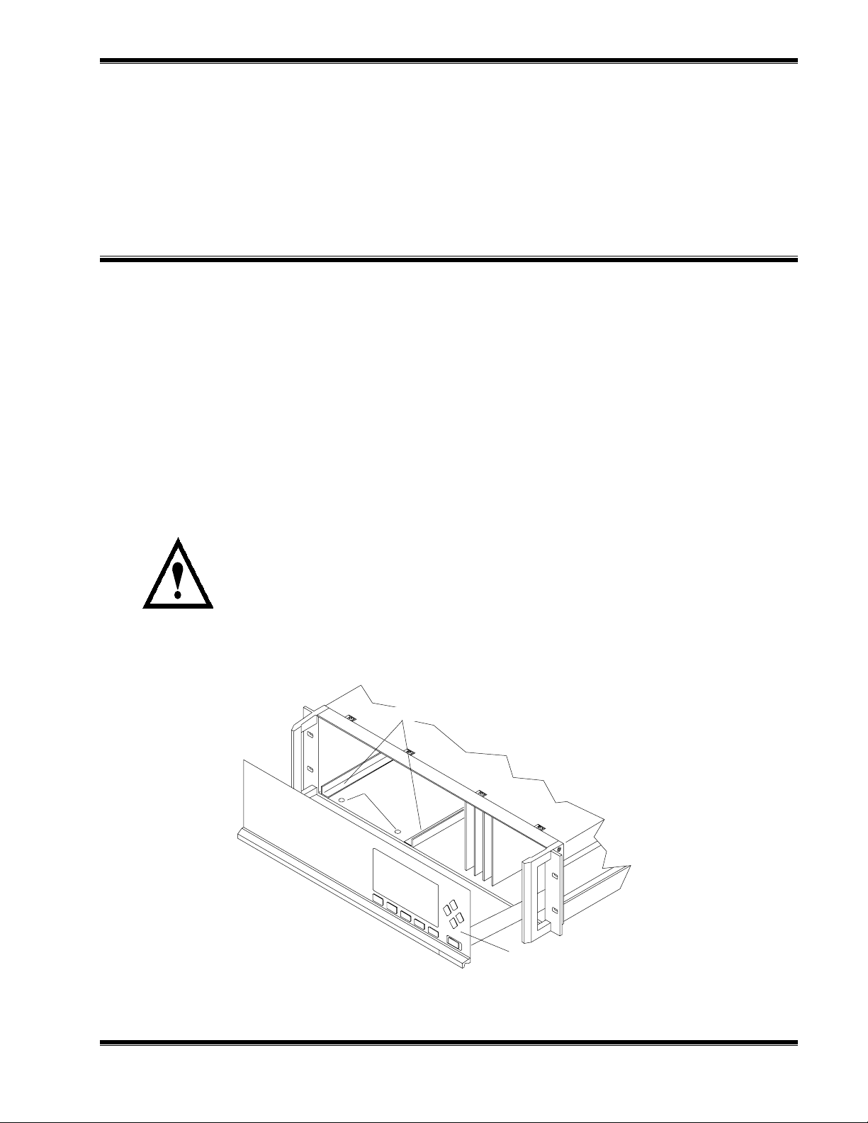
2.2 ASSEMBLY
If the Analyzer Module requires assembly with other components (e.g., the Platform
and associated I/O Modules), do so at this time. Following the guides on the bottom
left and bottom center of the Platform, carefully slide the Analyzer Module halfway into
place.
CAUTION: HAND INJURY HAZARD
Do not place hands or fingers in the Platform front handles when front panel is
open. Dropping the front panel of the Platform while hand or fingers are inside
either handle can cause serious injury.
ANALYZER MODULE GUIDES
PIN SEATS
DISENGAGED FRONT PANEL
F
IGURE
2-1. A
NALYZER MODULE INSTALLATION INTO INSTRUMENT PLATFORM
748362-B Rosemount Analytical December 1998
NGA 2000 Fast Response Paramagnetic Detector
2-1
Page 22

NGA 2000 F
AST RESPONSE PARAMAGNETIC DETECTOR
Lift the spring-loaded pins on the front of the Analyzer Module, and carefully slide it
the rest of the distance. Secure the module in position by releasing the pins, which
seat in the available holes in the bottom of the case (see Figure 2-1). If the module
and Platform are difficult to assemble, remove the module, ensure the top cover of the
module is firmly seated on the hold-down screws, and repeat the assembly procedure.
Install I/O Module(s) according to guidelines in the I/O manual. After startup and
calibration have been performed, secure the front panel with the six screws provided.
2.3 LOCATION
Install the Analyzer Module in a clean, non-hazardous, weather protected, vibration
free location free from extreme temperature variations. For best results, either install
the module near the sample stream to minimize sample transport time or supply a flow
greater than necessary and route only the appropriate amount through the Analyzer
Module.
Observing these requirements are critical. Note the following:
Excessive vibration can cause a noisy readout. To minimize vibration effects, the
detector/magnet assembly is enveloped in a shock-mounted compartment.
The user should ensure, when making any internal electrical connections, that no
cables are placed in contact with the detector assembly or associated internal sample
inlet and outlet tubing.
Magnetic susceptibilities and partial pressures of gases vary with temperature.
Permissible ambient temperature range is 32°F to 113°F (0°C to 45°C).
The interior of the Detector Assembly is maintained at approximately 144°F (62°C) by
an electronically controlled heater. Prior to entering the detector assembly, the
sample is heated in a coiled tubing to match the detector's temperature.
2.4 GASES
2.4.1 R
EQUIREMENTS
ALIBRATION GASES
C
Analyzer Module calibration requires the establishment of zero and span calibration
points. This requires a zero standard gas to set the zero point span gas to establish a
calibration point at or near the upper range limit.
An oxygen-free gas, typically nitrogen, is required for use as the zero standard gas.
Recommendations for span calibration gases, bases on various operating ranges, are
tabulated in Table 3-2. Air (20.93% oxygen) can be used as span gas regardless of
the ranges used for sampling, although very low ranges may lose accuracy.
2-2
Rosemount Analytical
December 1998
748362-B
Page 23

NSTALLATION
I
AMPLE GAS
S
Sample gas should be non-flammable.
EMPERATURE
T
Sample temperature at the inlet should be from 50°F to 150°F (10°C to 66°C). A
maximum entry temperature of 110°F (43°C) is recommended to prevent cooling of
the sample and possible internal condensation. Such condensation could damage
some components of the Analyzer Module. This recommendation can be ignored if a
thoroughly dry sample is examined.
RESSURE
P
Sample exhaust pressure limits are -5 to 10 psig (-345 to 690 hPa-gauge). Normal
operation is in the positive range, between 0 and 10 psig (0 and 690 hPa-gauge).
Negative gauge pressures are not normally recommended, but may be used in certain
special applications.
To prevent over-pressurization, insert a pressure relief valve into the sample inlet line.
A check valve should also be placed in the outlet line if the Analyzer Module is
connected to a manifold associated with a flare or other apparatus that does not
operate at atmospheric pressure.
The outlet port is commonly vented to the atmosphere. Any change in barometric
pressure has a directly proportional effect on the indicated percent of oxygen, and
should be neutralized through manual or computer correction of data. Note the
following example:
Range = 0% to 5% oxygen
Barometric pressure change after calibration = 1%
Analyzer Module measurement = 5% oxygen
Measurement error = 0.01 x 5% oxygen
Fullscale span = 5% oxygen
0.05% oxygen error = 1% of fullscale
The error is more significant for suppressed range 99% to 100%.
An optional barometric pressure compensation board is available to automatically
perform this correction.
A general rule regarding calibration gas pressure is that it should be the same as the
expected sample gas pressure during routine operation.
The above requirement increases the difficulty of operation at negative gauge
pressure. A suction pump can be connected to the outlet port for drawing sample
748362-B Rosemount Analytical December 1998
NGA 2000 Fast Response Paramagnetic Detector
2-3
Page 24

NSTALLATION
I
through the Analyzer Module. Such operation necessitates special precautions to
ensure accurate readout, including the following:
The need for equilibrium between sample and gas calibration pressures.
Any leakage in the sample handling system will decrease readout accuracy.
LOW RATE
F
Recommended sample flow rate is 800 to 1400 ml/min., ±40 ml/min. Optimum flow
rate is 1100 ml/min.
If flow is held to within tolerance and operating pressure remains constant, zero and
span drift will meet specified limits.
NETWORK 1
F
IGURE
2-2. FR-PMD F
RONT PANEL CONNECTIONS
OUT
IN
(69 kPa MAX)
NETWORK 2
POWER
FUSE
SAMPLE
10 PSI MAX
F
IGURE
2-4
2-3. FR-PMD B
ACK PANEL CONNECTIONS
December 1998 Rosemount Analytical 748362-BNGA 2000 Fast Response Paramagnetic Detector
Page 25

NSTALLATION
I
2.4.2 C
ONNECTIONS
(See Figure 2-3) Connect inlet and outlet lines for sample gas to appropriately labeled
fittings on the rear panel. Both connections are 1/4 inch ferrule-type compression
fittings.
Zero and span gases use the same inlet and outlet as the sample. Figure 2-4 shows
a typical external sample handling manifold for gas selection. Particulates must be
filtered down to two microns, gases generally require pressurization, and flow
measurement metering MUST be present.
2.4.3 L
EAK TEST
The Analyzer Module is thoroughly tested at the factory for gas leakage. The user is
responsible for testing for leakage only at the inlet and outlet fittings on the rear panel.
The user is also responsible for internal leak testing periodically and if any internal
pneumatic components are adjusted or replaced (with a test procedure selected by
the user).
Analyzer Module
Needle
Valves
Sample In
Flow Splitter
(≈2:1)
F
IGURE
Zero
Standard
Gas
Span
Standard
Gas
2-4. I
Two Micron
Filter
Flowmeter
NTERCONNECTION OF TYPICAL GAS MANIFOLD TO
A
NALYZER MODULE
FR-PMD
To Vent
2.5 ELECTRICAL CONNECTIONS
Note
Electrical connections must be in compliance with National Electrical Code
(ANSI/NFPA 70) and/or any applicable national or electrical codes.
748362-B Rosemount Analytical December 1998
NGA 2000 Fast Response Paramagnetic Detector
2-5
Page 26

NSTALLATION
I
Two electrical connections are required on the Analyzer Module; POWER and
NETWORK. See Figure 2-2. On the Analyzer Module, two NETWORK connections
are available, either of which is appropriate for : 1) interconnection with Backplane of
the Platform (see Platform instruction manual) or 2) "daisy chaining" with other NGA
2000 components.
Connect Analyzer Module POWER 24 VDC power source, either the Platform or
external power source.
J5
J10
J14
J6 J4
COMPUTER BOARD
J7
W1J19
FAN
CASE TEMP. SENSOR
FLOW SENSOR
J16
J1
J2
J3
MODULE BOARD
J20 J21 J22
SENSOR
MAGNET HEATER
THERMAL CUTOFF
SOURCE
J17
J9
J12
J15
LED
PREAMP
BOARD
DETECTOR
F
IGURE
2-6
2-5. FR-PMD W
IRING DIAGRAM
December 1998 Rosemount Analytical 748362-BNGA 2000 Fast Response Paramagnetic Detector
Page 27

4.3
[109]
8.4
[213]
6.2
[157]
8.2
[208]
[15]
NSTALLATION
I
.6
.5
[12]
C
2.8
[71]
D
E
[15]
1.1
[28]
[508]
.6
20.0
6.0
[152]
8.4
[213]
17.41
[442]
1.3
[36]
B
OUT
SAMPLE
IN
10 PSI MAX
(69 kPa MAX)
1.0
[25]
1.6
[41]
6.7
[170]
E. FUSE.
D. POWER CABLE TO NETWORK.
C. NETWORK CABLE CONNECTIONS TO PLATFORM.
B. SAMPLE OUT: 1/4" O.D. TUBE FITTING.
A. SAMPLE IN: 1/4" O.D. TUBE FITTING.
5. MODULE TO BE IN STALLED WITHIN ±15° OF HORIZONTAL..
4. POWER REQUIREMENTS: 24 VDC 3.5 A.
3. ELECTRICAL INSTALLATION MUST BE IN COMPLIANCE WITH NATIONAL ELECTRICAL
CODE (ANSI/NFPA 70) AND/O R ANY APPLICABLE NATIONAL OR LOCAL CODES.
2. MODULE IS NOT WEATHERPROOF.
1. APPROXIMATE WEIGHT: 15 LB (6.8 kg).
F
IGURE
748362-B Rosemount Analytical December 1998
2-6 O
UTLINE AND MOUNTING DIMENSIONS
NGA 2000 Fast Response Paramagnetic Detector
A
DIMENSIONS
INCH
[mm]
2-7
Page 28

NSTALLATION
I
N
OTES
2-8
December 1998 Rosemount Analytical 748362-BNGA 2000 Fast Response Paramagnetic Detector
Page 29

S
TARTUP AND OPERATION
3
3.1 OVERVIEW
Prior to initial startup, the user should perform the leak test procedure outlined in
Section 2.
For the remainder of this section, Analyzer Module interconnection with a Platform or
some interfacing component will be assumed. Display and keypad information shall
refer to that which the user can expect to see and do with regard to the front panel of
the Platform.
For a complete description of the Platform front panel controls and indicators, see the
Platform instruction manual.
3.2 DISPLAYS
Three kinds of Display screens are available to the user:
• Run Mode
• Menu
• Help
3.3 RUN MODE DISPLAY
The Run Mode is the normal mode of operation. In this mode, the Display (see Figure
3-1) will show current gas measurement, the component of interest, the current
operations of the softkeys, and a graphic bar representing the displayed concentration
as ppm or as a percent of oxygen.
If more than one Analyzer Module is connected to the system, the Run Mode display
will show as many as four gas measurements on screen. Alarm messages may also
appear on the display (See Table 3-1).
748362-B Rosemount Analytical December 1998
NGA 2000 Fast Response Paramagnetic Detector
3-1
Page 30

TARTUP AND OPERATION
S
3.4 MENU DISPLAYS
The menu structure enables the user to access data and functions, and put
information onto the network.
MESSAGE DISPLAY DESCRIPTION TYPE
BAROMETER System Barometer WARNING
CASE TEMP Case Temperature WARNING
CRUDE NOISE Calculated Noise WARNING
CURRENTRNGHI Current, High Range WARNING
CURRENTRNGLO Current, Low Range WARNING
DET TEM Detector Temperature WARNING
FAN FET Fan Current WARNING
HEATER FET Heater Current WARNING
T
ABLE
LED CURRENT LED Current WARNING
LIN ERROR Linearizer Error WARNING
LOOP CURRENT PMD Loop Current WARNING
N15 VOLTS Power Supply, -15V WARNING
P15 VOLTS Power Supply, +15V WARNING
P24 VOLTS Power Supply, +24V WARNING
P5 VOLTS Power Supply, +5v WARNING
RAW S IGNAL Raw Signal WARNING
SAMP PRES Sample Pressure WARNING
SVFLOW Sample Bypass Flow WARNING
BICELLA PMD Photo Sensor FAILURE
BICELLB PMD Photo Sensor FAILURE
SW ERROR Software Error FAILURE
3-1. FR-PMD A
NALYZER MODULE ALARMS
3-2
The Main Menu (Figure 3-2) is subdivided into three levels of control based generally
on which personnel is likely to use it: Basic Controls, Expert Controls and Setup, and
Technical Level Configuration. See Figures 3-3, 3-4, and 3-5. Many layers of the
menu structure are described at appropriate places throughout this manual.
From the Run Mode display, press the MENU softkey to enter the Main Menu (Figure
3-2).
December 1998 Rosemount Analytical 748362-BNGA 2000 Fast Response Paramagnetic Detector
Page 31

TARTUP AND OPERATION
y
y
y
y
S
See Figures 3-7 through 3-11 for flow charts depicting Menu screens related to this
Analyzer Module.
3.5 HELP DISPLAYS
The Help structure is intended to be an on-line "tutorial," context sensitive and topicinterconnected, so that the user can practically operate NGA 2000 without need of an
instruction manual (Figure 3-6).
Analyzer PQ 322-14
23.2% O2
F
IGURE
3-1. R
0 %
Secondar
Secondar
Secondar
Secondar
Variable: XXXX
Variable: XXX
Variable: XXXX
Variable: XXXX
Display Parms. Menu Dual Info
F1
UN MODE DISPLAY
23.2 % O2 Analyzer XXXXXXXX
Basic Controls
Expert controls and setup ...
(Operational configuration)
Technical level configuration ...
(Diagnostic and manufacturing/service)
Delete alarm message!
50
F2 F3 F4 F5
Main Menu
Display Parms. Info
F1
F
IGURE
748362-B Rosemount Analytical December 1998
3-2. M
AIN MENU DISPLAY
F2 F3 F4 F5
NGA 2000 Fast Response Paramagnetic Detector
3-3
Page 32

TARTUP AND OPERATION
g
p
p
S
23.2 % O2 Analyzer XXXXXXXX
Basic Controls
Measurement range numbers:
Range upper limit: 25%
Range and functional control: Local
Calibration ...
Status: Ready
Home Escape Zero Span Info
F
IGURE
F
IGURE
3-3. B
3-4. E
F1
F2 F3 F4 F5
ASIC CONTROLS MENU
23.2 % O2 Analyzer XXXXXXXX
ert controls and set u
Ex
Expert analyzer controls ...
Auxiliary module controls ...
System set up ...
Analyzer module set up ...
Auxiliary module set up ...
Home Escape Info
F1 F2 F3 F4 F5
XPERT CONTROLS AND SETUP MENU
23.2 %O2 Analyzer XXXXXXXX
Technical confi
System set up .. .
uration menu
F
IGURE
3-4
3-5. T
Service menus...
Diagnostic menus...
Other module diagnostic menus...
Listing of all modules...
Status: Normal
Home Info
F1
F2 F3 F4 F5
ECHNICAL LEVEL CONFIGURATION MENU
December 1998 Rosemount Analytical 748362-BNGA 2000 Fast Response Paramagnetic Detector
Page 33
23.2 % O2 Analyzer XXXXXXXX
p
Main Menu Hel
The Main Menu for the analyzer system.
Note that this menu refers to the particular
analyzer selected from t he run screen, when
used in a system. The s oftkey marked “HOME”
will always return you to this screen.
Help menu system...
Help on help...
Keyboard controls...
Editing controls.. .
Home Escape Map
F1 F2 F3 F4 F5
TARTUP AND OPERATION
S
F
IGURE
3-6. T
YPICAL HELP SCREEN
3.6 STARTUP PROCEDURE
Introduce a suitable on-scale gas (NOT actual sample) into sample inlet.
Apply power to the FR-PMD Analyzer Module. If it is associated with a Platform, do
this by plugging in the Platform to a power source. The Platform has no ON/OFF
power switch. Once power is supplied to the Platform, the FR-PMD Analyzer Module
will be energized.
If the user's system contains only one Analyzer Module, all system components, the
Controller Board and the network "self-install" (bind together) during initial startup. If
the system contains more than one Analyzer Module, the startup sequence will
interrogate the network to locate and identify all components on the network. The
user will have to bind appropriate combinations of components after the startup
sequence.
After the warm-up period, approximately one hour for FR-PMD Module, all modules
are completely functional.
Enter appropriate data in the Calibration Gas List (by making the following display
selections: Main Menu, Expert Controls and Setup [enter security code, if necessary],
Analyzer Module setup, Calibration Gas List). Also, enter appropriate values in the
Calibration Parameters menu (by making the following display selections: Main Menu,
Expert Controls and Setup [enter security code, if necessary], Analyzer Module Setup,
Calibration Parameters), particularly data related to which ranges are to be zeroed
together and how the Analyzer Module is expected to calibrate ranges (separately or
otherwise).
The Analyzer Module will not allow the user to increase the upper limit of a range
beyond the "maximum range" software setting. To change the "maximum range"
value, select the following from the Main Menu: Technical Configuration Menu,
Service Menu, Manufacturing Data, Analyzer Module Data. Select Maximum Range,
and use the arrow keys to scroll the indicated value. The same applies for "minimum
range" settings.
748362-B Rosemount Analytical December 1998
NGA 2000 Fast Response Paramagnetic Detector
3-5
Page 34

TARTUP AND OPERATION
S
3.7 BINDING
To achieve full coordination between Analyzer Modules and associated I/O Modules,
the user must bind those components together in the System Setup portion of the
Technical Configuration Menu in software. See Figure 3-10 of this manual and
Section 1.5 of the I/O Modules Manual for binding instructions.
3.8 CALIBRATION
Calibration consists of establishing zero and span calibration points. Generally, zero
and span calibration should be performed on the range that will be used during
sample analysis.
To calibrate the FR-PMD Analyzer Module, introduce zero gas into the SAMPLE
INLET, and do the following:
1. If the Multi-Analyzer Module, split Run Mode display is shown, press the DISPLAY
softkey until the desired Analyzer's Run Mode display is acquired.
2. Press the MENUS softkey to enter the Main Menu.
3. Press the ENTER key to enter the Basic Controls menu.
4. Press the ZERO softkey to enter the Zero/Span Calibration menu.
5. Press the ZERO softkey and wait.
6. Introduce span gas (Table 3-2) into the SAMPLE INLET.
7. Press the SPAN softkey and wait.
8. Press the HOME softkey to re-enter the Main Menu.
9. Press the DISPLAY softkey for the Run Mode display.
If the user is unable to calibrate the Analyzer Module (i.e., when ZERO or SPAN is
initiated, nothing happens), a possible solution relates to the use of an incorrect gas
for zeroing or spanning (e.g., using a high concentration gas to zero or a zero gas to
span the Analyzer Module). Recalibrating with the appropriate gas(es) WILL NOT
correct the problem because the ZERO OFFSET or SPAN FACTOR has been set to
an extreme value in the process.
To remedy the problem, do the following:
1. Select the following from the Main Menu: Expert Controls and Setup (enter
security code if necessary), Analyzer Module Setup, and Calibration Parameters.
3-6
2. Using the down arrow, select Zero Ranges, press ENTER and, using the up/down
arrows, toggle to SEPARATE. Do the same for the Span Ranges selection. Do
not press ESCAPE at any time unless retention of prior settings is desired.
3. Return to the Main Menu (HOME) and make the following selections: Expert
Controls and Setup (enter security code if necessary), Expert Analyzer Controls,
December 1998 Rosemount Analytical 748362-BNGA 2000 Fast Response Paramagnetic Detector
Page 35

TARTUP AND OPERATION
S
Zero/Span, Calibration Factors, and Range 1 (2, 3, 4) Factors. (Do steps 4 and 5
for each range.)
4. Select Zero Offset, press ENTER, adjust the value to 525000 with the up/down
arrow keys, and press ENTER. Do not press ESCAPE at any time unless
retention of prior settings is desired.
5. Select Span Factor, press ENTER, adjust the value to 0.000015 with the up/down
arrow keys, and press ENTER. Do not press ESCAPE unless retention of prior
settings is desired.
6. Attempt to recalibrate the Analyzer Module according to the procedure outlined at
the beginning of Section 3.8. If re-calibration fails, return to the Range Factors
menu, readjust factors, and attempt calibration again.
RANGE % OXYGEN
RECOMMENDED ZERO
STANDARD GAS
RECOMMENDED SPAN
STANDARD GAS
0 to 1 Nitrogen 0.9% O2, balance N
0 to 2.5 Nitrogen 2.3% O2, balance N
0 to 5 Nitrogen 4.5% O2, balance N
0 to 10 Nitrogen 9% O2, balance N
0 to 25 Nitrogen Air (20.93% O2)
0 to 50 Nitrogen 45% O2, balance N
2
T
ABLE
0 to 100 Nitrogen 100% O
3-2. C
ALIBRATION RANGE FOR VARIOUS ZERO BASED OPERATING RANGES
3.9 BACKGROUND GAS COMPENSATION
Any gas having a composition other than 100% oxygen contains background gas, that
is, non-oxygen components. Sometimes, the FR-PMD Module response to
background gas is significant, depending largely on the span and range used.
2
2
2
2
2
If the operator uses zero and span gases that contain the same background gas as
the sample, calibration procedures automatically compensate. No adjustments are
necessary.
If the background gas in the sample is different from that in the zero and/or span
gases, the operator must take into consideration background effects to ensure correct
readout. During entry of zero and span gas values in the Calibration Gas List, the
instrument is not set to indicate the true oxygen content of the zero and span standard
gases. It is set to indicate a slightly different value, relative to background gas,
calculated to provide correct readout during subsequent analysis of sample gas.
748362-B Rosemount Analytical December 1998
NGA 2000 Fast Response Paramagnetic Detector
3-7
Page 36

TARTUP AND OPERATION
A
S
XYGEN EQUIVALENT VALUES OF GASES
O
For computation of background corrections, the analyzer's response to each
component of the sample must be known. Table 3-3 lists the percentage oxygen
equivalent values for many common gases. For a more comprehensive list of oxygen
equivalent values, refer to a resource text such as the Handbook of Chemistry and
Physics for tables of ma gnetic susceptibility of substances. The percentage oxygen
equivalent of a gas can be determined by the following equation, assuming both gases
are supplied at the same pressure:
nalyzer Response to Gas
% O2 Equivalent of Gas =
Analyzer Response to O
X 100%
2
For example, if the analyzer's response to oxygen is +100%, the response to xenon
would be -1.34%.
The oxygen equivalent of a gas mixture is the sum of the contribution of the individual
gas components.
Example: Zero Based Range
At lower range limit (i.e., 0% O2), composition of sample is: 80% CO2, 20% N2.
From Table 3-3, the percent oxygen equivalents are: CO2 -0.623%, N2 -0.358%.
The percent oxygen equivalent of the mixture =
0.8(-0.623) + 0.2(-0.358) = ( -0.4984) + (-0.0716) = 0.570% O2.
OMPUTING ADJUSTED VALUES FOR CALIBRATION GAS LIST
C
Before calibrating the Analyzer Module, values in the Calibration Gas List must be
adjusted to correct for magnetic susceptibility of background gas. In the equation that
follows, the quantities are defined as follows:
3-8
BGGst = oxygen equivalent of background gas in standard gas (Table 3-3).
BGGs = oxygen equivalent of background gas in sample (Table 3-3).
OP = operating pressure. Unless special pressure corrections are to be made,
the zero standard, span standard and sample gases must all be admitted at the
same pressure.
Use the following equation to compute the adjusted settings for the Calibration Gas
List:
(A)[100 + (B-C)]-100[B-C]
Adjusted percent oxygen for standard gas =
100
December 1998 Rosemount Analytical 748362-BNGA 2000 Fast Response Paramagnetic Detector
Page 37

Where:
)
A = true percent oxygen of standard gas
B = BGGs
C = BGGst
Example:
Background gas in sample is CO2, oxygen equivalent = -0.623%.
TARTUP AND OPERATION
S
Zero gas is 100% N
Span standard gas is air: 21% O2, 79% N
2.
2.
Background gas in zero and span standard gases is N2, oxygen equivalent =
0.358%.
With N2 zero standard gas flowing, zero gas value in the Calibration Gas List
would be 0.265% O2 (as determined by the following):
0[100+(-0.623-(-0.358))] - 100{-0.623-(-0.358)]
100
= 0.265% O
2
With air flowing, span gas value in the Calibration Gas List would be 21.21%
oxygen (as determined by the following):
21(100 - 0.265) - 100 (-0.265
= 21.209% O2 ≅ 21.21 O
2
100
In two limiting cases, the general equation is reduced to simpler forms.
If the span standard gas is 100% oxygen, the adjusted oxygen value is the same as
the true value (i.e., 100% O2).
If the zero standard is an oxygen-free zero gas, the adjusted value for setting the
ZERO Control = BGGst-BGGs. (If the oxygen-free zero gas is more diamagnetic than
the background gas in the sample, this difference is negative. The negative value
may be entered in the Calibration Gas List.)
Alternately, the user can avoid these compensation calculations by using zero and
span gases which have been specially prepared to contain the expected amounts of
background gas. Calibration of the analyzer module will then factor in background gas
effects in the same proportions as normal run mode measurement.
748362-B Rosemount Analytical December 1998
NGA 2000 Fast Response Paramagnetic Detector
3-9
Page 38

TARTUP AND OPERATION
S
GAS EQUIV. % AS O
Acetylene, C2H
Allene, C3H
4
Ammonia, NH
2
-0.612 Hydrogen Bromide, Hbr -0.968
-0.744 Hydrogen Chlori de, HC
3
-0.479 Hydrogen Fluoride, HF -0.253
2
GAS EQUIV. % AS O
1
-0.650
Argon, A -0.569 Hydrogen Iodide, HI -1.403
Bromine, Br
1,2
-Butadiene, C4H
1,3
-Butadiene, C4H
n-Butane, C4H
iso-Butane, C4H
Butene-1, C4H
cis Butene-2, C4H
iso-Butene, C4H
trans Butene-2, C4H
Carbon Dioxide, CO
Carbon Monoxide, CO -0.354 n-Pentane, C5H
Ethane, C2H
2
6
6
10
10
8
8
8
8
2
6
-0.83 Hydrogen Sulfide, H2S -0.751
-1.047 Kr y pto n , K r -0.853
-0.944 Me t h a n e , CH
4
-0.512
-1.481 Ne o n , N e -0.205
-1.485 Nitric Oxide, NO +44.2
-1.205 Ni t r oge n , N
-1.201 Nitrogen Dioxide, NO
2
2
-0.358
+28.7
-1.274 Nitrous Oxide, N2O -0.560
-1.274 n-Octane, C8H
-0.623 Ox yge n , O
-0.789 iso-Pentane, C5H
18
2
12
12
-2.840
+100.0
-1.810
-1.853
2
Ethylene, C2H
4
-0.553 neo-Pentane, C5H
Helium, He -0.059 Propane, C3H
n-Heptane, C7H
n-Hexane, C6H
cyclo-Hexane, C6H
Hydrogen, H
T
ABLE
3-3. O
16
14
12
2
-2.508 Pr o p yle n e , C3H
-2.175 Wate r, H2O -0.381
-1.915 Xenon, Xe -0.340
-0.117
XYGEN EQUIVALENTS OF COMMON GASES
12
8
6
-1.853
-1.135
-0.903
3-10
December 1998 Rosemount Analytical 748362-BNGA 2000 Fast Response Paramagnetic Detector
Page 39

TARTUP AND OPERATION
S
Measurement range number: 1
Range upper limit: 10000 ppm
Range and functional control: LOCAL
Zero gas concentration: 0 ppm
Span gas concentration: 9980 ppm
Sample flow: 1000 ml/min
Ranges with valid calibration: 1&2
Calibration status: Ready
If it won’t calibrate...
Are you sure?
You must have zero gas flowing through
the analyzer.
This control does NOT control any autocal. Module bound to this analyzer!
If you are sure, press ZERO again now.
Press left arrow key when you are done.
Calibration status: Ready
Error message for last zero: 24-08-94
Basic controls
ZERO
Analyzer Zero
Basic cont rols...
Expert controls and setup...
(Operational configuration)
Technical level configuration...
(Diagnostic and manufacturing/service)
Enter your security code with softkeys.
Security codes are set in the system setup
menu in the Technical level menus.
Press five characters when Security code
says READY. Press six to return to
“READY”.
Security code: 54321
Expert analyzer controls...
Auxiliary module controls...
System set up...
Analyzer module set up...
Auxiliary module set up...
Local I/O set up...
SPAN
Are you sure?
You must have zero gas flowing through
the analyzer.
This control does NOT control any autocal. Module bound to this analyzer!
If you are sure, press SPAN again now.
Press left arrow key when you are done.
Calibration status: Ready
Error message for last zero: 24-08-94
Analyzer Span
Main Menu
Basic level security
(expert, technical)
Expert controls and setup
Current measurement parameters
Analyzer gas measured: O2
Measurement range number: 1
PARMS
MORE
Technical configuration menu
System set up...
Service menus...
Diagnostic menus...
Other module diagnostic menus...
Listing of all modules...
Expert and Technical menus follow in
succeeding flow charts.
Check that you are flowing the correct gas, and the gas
concentration is what it is supposed to be. Make sure that the
reading is stable before starting. If you have enabled or disabled the
linearizer, you may have made it hard for the analyzer to calibrate.
If so, go to the calibration parameters screen under Expert controls
and setup, under Analyzer set up, and disable the limits checking.
Re-calibrated, then disable the limits checking again. If all else fails,
manually adjust the calibration factors until the readings are close to
correct and try again.
If it won’t calibrate...
Range change control: Local
Linearization mode: N/A
Analyzer operational state: Normal
Analyzer alarm state: Normal
Alarms reporting level: Failure
Current measurement parameters
Response time: 2.0 Secs
Bypass sample flow: 1000 ml/min.
Sample pressure: 12.3 hPa
Detector Temperature: 55.3°C
F
IGURE
3-7. D
ISPLAY SCREENS
(1
748362-B Rosemount Analytical December 1998
OF
5)
NGA 2000 Fast Response Paramagnetic Detector
3-11
Page 40

TARTUP AND OPERATION
S
From MAIN MENU
Expert controls and setup
Expert analyzer controls...
Auxiliary module controls...
System set up...
Analyzer Module set up...
Auxiliary Module set up...
Local I/O set up...
Analyzer module set up...
and Auxiliary module set up...
outlined in the next flow chart.
Local I/O set up information is
included in the I/O Modules manual.
Measurement range number: 1
Range lower limit: 0 ppm
Range upper limit: 10000 ppm
Linearizer: N/A
Range and functional control: LOCAL
Zero/Span calibration…
Ranges with valid calibration: 1&2
Physical Measurements…
#1
Measurement range number: 1
Zero gas concentration: 0 ppm
Span gas concentration: 9980 ppm
Sample flow: 1000 ml/min.
Raw measurement signal: 0.3256 V
Ranges with valid calibration: 1&2
Status: Ready
Result...
Calibration adjustment limits: Enabled
Expert controls
CAL
Zero/Span Calibration
Auxiliary module controls
This screen selects any module with a
control screen. This includes any auto
calibration or sample module bound to
this analyzer.
Module Tag
Module Tag
Dependent on which auxiliary module
is present on the network.
See I/O Modules manual.
Secondary Measurements
Sample flow: 900 ml/min.
Flow lower limit: 800 ml/min.
Flow upper limit: 1400 ml/min.
Sample pressure: 12.3 hPa
Case temperature: 54.3 C
Front panel control...
Display resolution...
Auxiliary lines...
System Set Up
See Platform manual for a flow chart
of these displays.
#2
Date of last zero: 24-08-94
Error message for last zero: 24-08-94
Error percentage for last zero: 5%
Raw signal at last zero: 500000
Last zero gas would read: -0.83 ppm
Date of last span: 24-08-94
Error message for last span: Great!
Error percentage for last span: 5%
Raw signal at last span: 500000
The last span gas would read: 113 ppm
CAL DATA
Zero/Span diagnostic data
CAL DATA
See #2 on this
flow chart.
F
IGURE
3-12
FACTORS
See #3 on this
flow chart.
3-8. D
Are you sure?
You must have zero gas flowing through
the analyzer.
This control does NOT control any autocal module bound to this analyzer!
If you are sure, press ZERO again now.
Press left arrow key when you are done.
Calibration status: Ready
Error message for last zero: 24-08-94
ISPLAY SCREENS
ZERO SPAN
Analyzer Zero
Range 1 (2,3,4) Factors
Manufacturer’s settings
Zero offset: 0
Span factor: 1000
Zero offset 500000
Span factor: 500000
(2
OF
Stored settings
5)
Are you sure?
You must have span gas flowing through
the analyzer.
This control does NOT control any autocal module bound to this analyzer!
If you are sure, press SPAN again n ow.
Press left arrow key when you are done.
Calibration status: Ready
Error message for last zero: 24-08-94
Analyzer Span
December 1998 Rosemount Analytical 748362-BNGA 2000 Fast Response Paramagnetic Detector
HISTORY
FACTORS
#3
Calibration Factors
Range 1 factors...
Range 2 factors...
Range 3 factors...
Range 4 factors...
Zero compensation factor: 1
Span compensation factor: 1
Range 1 (2,3,4) Factors
Zero offset: 525000
Span factor: 0.000015
Fullscale range at calibration: 10 ppm
Measurement range number: 1
Hardware zero offset: 2047
Raw measurement signal: 525000
Page 41

From MAIN MENU
Expert controls and setup
Expert analyzer controls...
Auxiliary module controls...
System set up...
Analyzer Module set up...
Auxiliary Module set up...
Local I/O set up...
For Expert analyz er
controls, Auxiliary module
controls, and System set up
menus, see preceding flow
chart.
Analyzer module set up
Calibration gas list...
Calibration param eters...
Gas measurement paramet er s...
Analyzer parameter list...
Physical measurement par ameters...
Displayed parameters...
Analyzer tag: PmO2
Auxiliary module set up
Select an auxiliary module for set up
Module Tag
Module Tag
Module Tag
Module Tag
Module Tag
Module Tag
Module Tag
Dependent on which auxiliary module
is bound to the analyzer.
See I/O Modules manual.
See I/O Modules manual for Local I/O
set up information.
Calibration gas list
Zero gas - range 1: 0 %
Span gas - range 1: 0.935 %
Zero gas - range 2: 0 %
Span gas - range 2: 2.235 %
Zero gas - range 3: 0 %
Span gas - range 3: 9.786 %
Zero gas - range 4: 0 %
Span gas - range 4: 100 %
Calibration…
Calibration Parameters
Calibration adjustment limi ts: Enabled
Calibration averaging time: 5 Secs
Calibration failure alarm: Yes
Cal failure error allowed: 5%
Calibration time out: 60 Secs
Zero ranges: All
Span ranges: SEPARATELY
Gas measurement parameters
Linearization parameters...
Response time/delay param eters...
Range setting...
Units...
Linearization functions...
Analyzer Parameter List
Analyzer tag: PmO2
First line’s parameter: Flow
Second line’s parameter: S amp. pres.
Third line’s parameter:
Fourth line’s paramet er :
#4
Physical Measurement
Parameters
Sample flow:: 1000 ml/min
Sample pressure: 12.3 kPa
Case Temperature: 54..3 C
Detector Temperature: 55.3 C
Flow limits...
Pressure limits...
Temperature limits...
See #1 in previous flow chart.
Linearization parameters
Range 1 linearizer: Enabled
if enabled, uses curve no.: 1
Range 2 linearizer: Enabled
if enabled, uses curve no.: 2
Range 3 linearizer: Enabled
if enabled, uses curve no.: 3
Range 4 linearizer: Enabled
if enabled, uses curve no.: 4
Set coeffi c ients…
Response time/delay parameters
Range 1 t90 time: 10 Secs
Range 2 t90 time: 1 Secs
Range 3 t90 time: 1 Secs
Range 4 t90 time: 1 Secs
LON update rate: 10x/Sec
Output delay time: 0 Secs
Range Settings
Minimum range: 0.5%
Maximum r ange: 100 %
Range 1 lower limit: 0 %
Range 1 upper limit: 1
%
Range 2 lower limit: 0 %
Range 2 upper limit: 2 %
Range 3 lower limit: 0 %
Range 3 upper limit: 10 %
Range 4 lower limit: 0 %
Range 4 upper limit: 100 %
Gas measurement units: ppm
Pressure measurement units: psig
Temperature measurement units: F
Variables are still sent as the basic SI unit.
Polynomial set up...
Midpoint correction set up...
Units
Linearization functions
Analyzer Parameter List
Primary Variable Parameters
Control mode: LOCAL
Output delay time: 0 Secs
Range 1 upper limit: 1 %
Range 2 upper limit: 2 %
Range 3 upper limit: 10 %
Range 4 upper limit: 100 %
Range 1 lower limit: 0 %
Range 2 lower limit: 0 %
Calibration
NEXT
Flow Limits
Sample flow upper l imit: 1400 m l/min
Sample flow lower limit: 800 ml/min
Pressure Limits
Sample upper limit: 150 hPa
Sample lower limit: 100 hPa
Range 3 lower limit: 0 %
Range 4 lower limit: 0 %
Analyzer Parameter List
Calibration Parameters
Calibration mode: Local
Calibration averaging time: 5
Secs
Calibration failure alarm: Yes
Cal failure error allowed: 5%
Calibration time out: 60 Secs
Ranges zeroed: All
TARTUP AND OPERATION
S
Linearity coefficients
Curve 1 (2,3,4)
AO coeffi c ient: 1.34523E-4
A1 coefficient: 0.983751
A2 coefficient: 0.115751
A3 coefficient: 1.11575E-6
A4 coefficient: 7.3421E-12
Curve upper limit: 1%
Curve over- r ange: 10%
Curve under-range: 5%
Status: Enabled
Polynomial set up
Range to be linearized: 1
Current span gas: 9.89 ppm
Calculated polynom ial order : 4
Gas values shown as: Percent
Gas concentrations...
Analyzer function: Ready
Gas concentrations
Gas value: 0
Raw reading: 0 ppm
Linearized values: 0 ppm
Gas value: 10
Raw reading: 11 ppm
Linearized values: 10 ppm
Point to be measured: Point 1
Analyzer function: Ready
Point 1
Point 2
Midpoint correction set up
Range 1 (2,3,4)
Correction: Disabled
Point being measured: Pt 1
Point 1 gas concentration: 100 ppm
Point 2 gas concentration: 150 ppm
Point 3 gas concentration: 150 ppm
Point 1 reading: 100 ppm
Point 2 reading: 120 ppm
Point 3 reading: 150 ppm
Span gas value: 100 ppm
Analyzer function: Ready
Analyzer Parameter List
Primary Variable Parameters
Range 1 t90 time: 10 Secs
Range 2 t90 time: 1 Secs
Range 3 t90 time: 1 Secs
Range 4 t90 time: 1 Secs
Linearizer on range 1: Enabl ed
Linearizer on range 2: Enabl ed
Linearizer on range 3: Enabl ed
Linearizer on range 4: Enabl ed
Analyzer Parameter List
Calibration Gases
Zero gas - range 1: 0 %
Zero gas - range 2: 0 %
Zero gas - range 3: 0 %
Zero gas - range 4: 0 %
Span gas - range 1: 0.935 %
Span gas - range 2: 2.235 %
Span gas - range 3: 9.785 %
Span gas - range 4: 100 %
Displayed Parameters
First line’s parameter: Flow
Second line’s parameter: S amp pres
Third line’s parameter:
Fourth line’s paramet er :
May be displayed on the appropriat e
line of the singl e analyzer display
screen.
F
IGURE
3-9. D
ISPLAY SCREENS
(3
748362-B Rosemount Analytical December 1998
OF
Temperature Limits
Case upper limit: 55°C
Case lower limit: 45°C
5)
NGA 2000 Fast Response Paramagnetic Detector
3-13
Page 42

TARTUP AND OPERATION
S
From MAIN MENU
Technical configuration menu
System set up...
Service m enus...
Diagnostic menus...
Other module diagnostic menus...
Listing of all modules...
For diagnostic menus, Other
module diagnostic m enus, and
listing of all modules, see
succeeding flow chart.
System set up
Main display configuration...
Front panel control...
Date and time...
Module binding...
System reset...
Security codes...
System tag: Rosemount
Main display configuration, Front
panel control, and Date and time
displays can be found in Pl atform
manual.
Module binding
Analyzer module selec ted: PmO2
Select modules...
Proposed bind:
View bindings...
Bind selections!
Unbind everythi ng!
System reset
Are you sure?
Re-initializing will destroy all binds!
System reset!
Re-initialize networks!
#5
Record security codes
Basic level secur ity: Enabled
Expert level security: Enabled
Technical level security: Enabled
Record basic level security codes...
Record expert level security codes...
Record technical level security codes.. .
Manufacturing data
Control module data. ..
Analyzer module data...
Module Tag
Module Tag
Module Tag
Module Tag
Module Tag
Module Tag
Module Tag
Module Tag
Select I/O modules
Select the modules you wish to bind to the
current analyzer.
Module Tag
Module Tag
Module Tag
Module Tag
Module Tag
Module Tag
Module Tag
Module Tag
Modules Bound
Analyzer module selec ted: PmO2
Auxiliary module: Auto 1023
Auxiliary module: Acal 2322
Auxiliary module: HART 1092
Auxiliary module: none
Auxiliary module: none
Auxiliary module: none
Proposed new bind:
Record basic level security
(expert, technical menu the same)
Press five soft keys in any order to def ine
the code. The actual code is represented
by the order in which they are pressed,
and shown numerically below. Press the
left arrow key when you are done.
Actual code number: 54321
Control Unit Manufacturing Data
Control unit serial number: 800002356
Manufacturing date code: 12-08-93
Hardware revision number: 1.00
Software revision number: 1.09
Revision notes...
User tag number: PV1c
Analyzer Manufacturing Data
Analyzer module s/n: 8900189342
Manufacturing date code: 17-08-93
Bench configurati on c ode: PMD
Hardware revision number: 1.13
Software revision number: 1.03
Minimum range: 0.5%
Maximum r ange: 100 %
Measured gas: O2
User tag number: PmO2
F
IGURE
3-14
Manufacturing data. ..
Service history...
In maintenance since: N/A
Record security codes...
3-10. D
ISPLAY SCREENS
Service menus
Control module data. ..
Analyzer module data...
Module Tag
Module Tag
Module Tag
Module Tag
Module Tag
Module Tag
Module Tag
Module Tag
see #5 above
(4
OF
Service history
Record security code
Technical level security
5)
December 1998 Rosemount Analytical 748362-BNGA 2000 Fast Response Paramagnetic Detector
IO Module Manufacturing Data
See I/O Modules manual.
Control Module Service History
Manufacturing date: 12-08-93
In service date: 01-23-94
Last service date: 01-23-94
List notes...
Add service date!
Analyzer Module Service History
Manufacturing date: 17-08-93
In service date: 21-06-94
Last zero calibration date: 24-08-94
Last span calibration date: 24- 08- 94
Last service date: 21-06-94
List notes...
Add service date!
I/O Module Service History
See I/O Modules manual.
Page 43

TARTUP AND OPERATION
S
From MAIN MENU
Technical configuration menu
System set up...
Service m enus...
Diagnostic menus...
Other module diagnostic menus...
Listing of all modules...
For System set up and
Service menus, see
preceding flow charts.
Diagnostic menus
Control module diagnostics...
Analyzer Module diagnostics...
Module Tag
Module Tag
Module Tag
Module Tag
Module Tag
Module Tag
Module Tag
Other module diagnostics
This screen reserved for other modules
if present.
Module Tag
Module Tag
Module Tag
Module Tag
Module Tag
Module Tag
Module Tag
Listing of all modules
Lists all modules detected on the
network. Jumps to the module's
diagnostic screen.
Module Tag
Module Tag
Module Tag
Module Tag
Module Tag
Module Tag
For Control Unit Di agnostics, see the
Platform manual.
#6
Analyzer Diagnostics
Power supply voltages...
Primary variable parameters...
Physical measurement s parameters...
Temperature control parameters...
Miscellaneous control parameters...
Barometric pressure param eters...
Software diagnostics...
Analog output module
Power supplies...
Analog output...
Relay status...
Digital input lines...
Slot position: 1
Current range: 1
IO Module ID: Auto 1043
Analyzer Diagnostics
See #6 above.
Analyzer diagnostics
Power supply voltages
+15V analog is: 14.88 V
+15V analog was: 14.92 V
-15V analog is: -14.85 V
-15V analog was: -14.92 V
+5V digital is: 5.02 V
+5V digital was: 4.98 V
+24V power is: 23.8 V
+24V power was: 24.2 V
Primary variables parameters
Raw measurement signal: 0.3256 V
Bicell #1 signal: 0.250 V
Bicell #2 signal: 0.251 V
Pk-pk noise: 0 ppm
Loop current: 25 A
Calibration f ac tors...
Physical measurements
See #4 in previous flow chart.
Temperature control
Fan lower setpoint: 35 C
Fan upper setpoint: 50 C
Minimum fan duty cycle: 50 %
Case temperature: 35.4 C
Detector setpoint: 61.8 C
Detector P gain: 0.2
Detector I gain: 0.0005
Detector bias: 0.2
Detector temperature: 60.9
Miscellaneous control parameters
Fan current: 35 mA
Fan duty cycle: 50 %
Source LED current: 83 mA
Heater current: 1.7 A
Heater duty cycle: 50 %
Alarm message valid for: Failure
Barometric pressure parameter s
Pressure transducer: Present
Barometric pres. Compensation: Enabled
Measured pressure: 123 hPa
Transducer offset: 1000
Transducer slope: 1.0
Transducer PGA gain: 10
Software diagnostics
Last message: No error
And: No error
And: No error
And: No error
And: No error
And: No error
And: No error
And: No error
Edit to reset: Report
Software error code (1=no error): 1
Calibration factors
See #3 in previous flow chart.
F
IGURE
3-11. D
ISPLAY SCREENS
(5
748362-B Rosemount Analytical December 1998
OF
5)
NGA 2000 Fast Response Paramagnetic Detector
3-15
Page 44

TARTUP AND OPERATION
S
N
OTES
3-16
December 1998 Rosemount Analytical 748362-BNGA 2000 Fast Response Paramagnetic Detector
Page 45

M
AINTENANCE AND TROUBLESHOOTING
4
CAUTION: QUALIFIED PERSONNEL
This equipment should not be adjusted or repaired by anyone except properly
qualified service personnel.
4.1 OVERVIEW
FR-PMD Analyzer components that may require replacement include:
• All printed circuit board
• Thermal fuse inside Detector
• Case temperature sensor
• Flow sensor
• Power fuse
• Detector
• Module fan
The LED bi-cell assembly source requires adjustment (rotation) anytime the detector
is disassembled. Refer to Figures 4-1 through 4-4 for locations of these components.
4.2 PRINTED CIRCUIT BOARD REPLACEMENT
Refer to Figure 4-1 for locations of the Module, Computer, and (optional) Pressure
Compensation Boards.
The Module Board is secured to the inside of the analyzer module cover and the
Computer and Compensation Boards mount onto the Module Board. See Figure 4-1.
To remove individual boards, label and unplug all interconnection wiring, and remove
securing hardware. Reverse this procedure for installation.
748362-B Rosemount Analytical December 1998
NGA 2000 Fast Response Paramagnetic Detector
4-1
Page 46

AINTENANCE AND TROUBLESHOOTING
M
DETECTOR
(see Figures 4-3, 4-4)
MODULE
BOARD
PRESSURE
COMPENSATION
BOARD
ANALYZER
MODULE
COVER
COMPUTER
BOARD
FAN
(see Figure 4-2)
FLOW
SENSOR
CASE
TEMPERATURE
SENSOR
F
IGURE
4-2
4-1. FR-PMD M
ODULE ASSEMBLY
- E
XPLODED VIEW
December 1998 Rosemount Analytical 748362-BNGA 2000 Fast Response Paramagnetic Detector
Page 47

AINTENANCE AND TROUBLESHOOTING
M
4.3 MODULE FAN REPLACEMENT
The Analyzer Module fan assembly is disassembled as shown in Figure 4-2.
F
IGURE
4-2. M
ODULE FAN ASSEMBLY
4.4 THERMAL FUSE REPLACEMENT
See Figure 4-4 for location of the Detector Thermal Fuse. Remove the Detector
Assembly from the detector housing, replace the thermal Fuse. Reassemble in
reverse order.
4.5 FLOW SENSOR REPLACEMENT
See Figure 4-1 for location of Flow Sensor. To replace the sensor, remove
connections to sample gas line and disconnect securing hardware. Reassemble in
reverse order.
4.6 POWER FUSE REPLACEMENT
The power fuse is accessible through the front panel of the FR-PMD Analyzer. To
remove the fuse, push and turn the fuseholder cap 1/4 turn counterclockwise. Verify
that the replacement fuse is the same type and rating.
748362-B Rosemount Analytical December 1998
NGA 2000 Fast Response Paramagnetic Detector
4-3
Page 48

AINTENANCE AND TROUBLESHOOTING
M
DETECTOR HOUSING
DETECTOR
(see Figure 4-4)
F
IGURE
4-3. D
BASE
INSULATOR
BASE
ETECTOR ASSEMBLY
4-4
December 1998 Rosemount Analytical 748362-BNGA 2000 Fast Response Paramagnetic Detector
Page 49

AINTENANCE AND TROUBLESHOOTING
M
SENSOR
THERMAL CUTOFF
FUSE
HEATER
F
IGURE
DETECTOR
SENSOR BLOCK
HEATER BLOCK
PAD
4-4. D
ETECTOR
- E
XPLODED VIEW
BI-CELL
PREAMP BOARD
LED SOURCE
ASSEMBLY HOLDER
LED SOURCE
748362-B Rosemount Analytical December 1998
NGA 2000 Fast Response Paramagnetic Detector
4-5
Page 50

AINTENANCE AND TROUBLESHOOTING
M
N
OTES
4-6
December 1998 Rosemount Analytical 748362-BNGA 2000 Fast Response Paramagnetic Detector
Page 51

R
EPLACEMENT PARTS
5
WARNING: PARTS INTEGRITY
Tampering with or unauthorized substitution of components may adversely
affect safety of this product. Use only factory-approved components for repair.
5.1 REPLACEMENT PARTS
622917
655520 Computer Board
655670 Pressure Compensation Board
655856
655893 Fan
1
1
Sensor, RTD - Detector
Source/Holder Assembly
656576 Sensor, Case Temperature
657217
657253 Detector Assembly
657262
657892 Module Board
898733
902931 Sensor, Flow
903347 Fuse, Time-Delay 6A 250 VAC
1
Included in 657253 Detector Assembly
1
1
1
Preamp Board
Bi-Cell
Thermal Cutoff Fuse, Detector
748362-B Rosemount Analytical December 1998
NGA 2000 Fast Response Paramagnetic Detector
5-1
Page 52

EPLACEMENT PARTS
R
N
OTES
5-2
December 1998 Rosemount Analytical 748362-BNGA 2000 Fast Response Paramagnetic Detector
Page 53

A
PPENDIX
A. FR-PMD I
DENTIFICATION
M
ATRIX
A
Each analyzer is configured per the customer sales order. Below is the FR-PMD sales
matrix which lists the various configurations available.
To identify the configuration of an analyzer, locate the analyzer name-rating plate.
The 12-position sales matrix identifier number appears on the analyzer name-rating
plate.
O NGA 2000 Fast Response Paramagnetic Oxygen
Code Language
A English
X Special
Code Configuration Identifier
A10 Calibrated Standard Ranges: 0-5, 0-10, 0-25, 0-100%
A15 Calibrated Standard Ranges: 0-1, 0-5, 0-10, 0-25%
X99 Special Calibration Ranges
Code Detector Type
A00 Rhodium Plated Current Loop
Z00 Titanium Current Loop (Standard)
ZZZ No Selection
Z No Selection
O A A10 Z00 ZZZ Z Example
748362-B Rosemount Analytical December 1998
NGA 2000 Fast Response Paramagnetic Detector
A-1
Page 54

PPENDIX
A
N
OTES
A. FR-PMD I
DENTIFICATION MATRIX
A-2
December 1998 Rosemount Analytical 748362-BNGA 2000 Fast Response Paramagnetic Detector
Page 55

ENERAL PRECAUTIONS FOR HANDLING AND
G
TORING HIGH PRESSURE GAS CYLINDERS
S
Edited from selected paragraphs of the Compressed
Gas Association's "Handbook of Compressed Gases"
published in 1981
Compressed Gas Association
1235 Jefferson Davis Highway
Arlington, Virginia 22202
Used by Permission
1. Never drop cylinders or permit them to strike each other violently.
2. Cylinders may be stored in the open, but in such cases, should be protected against
extremes of weather and, to prevent rusting, from the dampness of the ground. Cylinders
should be stored in the shade when located in areas where extreme temperatures are
prevalent.
3. The valve protection cap should be left on each cylinder until it has been secured
against a wall or bench, or placed in a cylinder stand, and is ready to be used.
4. Avoid dragging, rolling, or sliding cylinders, even for a short distance; they should be
moved by using a suitable hand-truck.
5. Never tamper with safety devices in valves or cylinders.
6. Do not store full and empty cylinders together. Serious suckback can occur when an
empty cylinder is attached to a pressurized system.
7. No part of cylinder should be subjected to a temperature higher than 125°F (52°C). A
flame should never be permitted to come in contact with any part of a compressed gas
cylinder.
8. Do not place cylinders where they may become part of an electric circuit. When electric
arc welding, precautions must be taken to prevent striking an arc against the cylinder.
4125 E
AST LA PALMA AVENUE
Rosemount Analytical Inc.
• A
J
, C
NAHEIM
ULY
ALIFORNIA
1997 • 748525-C • P
92807-1802 • 714-986-7600 • FAX 714-577-8006
RINTED IN
USA
Page 56

(blank)
Page 57

ARRANTY
W
Goods and part(s) (excluding consumables) manufactured by Seller are warranted to be free from
defects in workmanship and material under normal use and service for a period of twelve (12)
months from the date of shipment by Seller. Consumables, glass electrodes, membranes, liquid
junctions, electrolyte, o-rings, etc., are warranted to be free from defects in workmanship and
material under normal use and service for a period of ninety (90) days from date of shipment by
Seller. Goods, part(s) and consumables proven by Seller to be defective in workmanship and/or
material shall be replaced or repaired, free of charge, F.O.B. Seller's factory provided that the goods,
part(s) or consumables are returned to Seller's designated factory, transportation charges prepaid,
within the twelve (12) month period of warranty in the case of goods and part(s), and in the case of
consumables, within the ninety (90) day period of warranty. This warranty shall be in effect for
replacement or repaired goods, part(s) and the remaining portion of the ninety (90) day warranty in
the case of consumables. A defect in goods, part(s) and consumables of the commercial unit shall
not operate to condemn such commercial unit when such goods, part(s) and consumables are
capable of being renewed, repaired or replaced.
The Seller shall not be liable to the Buyer, or to any other person, for the loss or damage directly or
indirectly, arising from the use of the equipment or goods, from breach of any warranty, or from any
other cause. All other warranties, expressed or implied are hereby excluded.
IN CONSIDERATION OF THE HEREIN STATED PURCHASE PRICE OF THE GOODS, SELLER
GRANTS ONLY THE ABOVE STATED EXPRESS WARRANTY. NO OTHER W ARRANTIES ARE
GRANTED INCLUDING, BUT NOT LIMITED TO, EXPRESS AND IMPLIED WARRANTIES OR
MERCHANTABILITY AND FITNESS FOR A PARTICULAR PURPOSE.
Limitations of Remedy. SELLER SHALL NOT BE LIABLE FOR DAMAGES CAUSED BY DELAY IN
PERFORMANCE. THE SOLE AND EXCLUSIVE REMEDY FOR BREACH OF WARRANTY SHALL
BE LIMITED TO REPAIR OR REPLACEMENT UNDER THE STANDARD W ARRANTY CLAUSE. IN
NO CASE, REGARDLESS OF THE FORM OF THE CAUSE OF ACTION, SHALL SELLER'S
LIABILITY EXCEED THE PRICE TO BUYER OF THE SPECIFIC GOODS MANUFACTURED BY
SELLER GIVING RISE TO THE CAUSE OF ACTION. BUYER AGREES THAT IN NO EVENT
SHALL SELLER'S LIABILITY EXTEND TO INCLUDE INCIDENTAL OR CONSEQUENTIAL
DAMAGES. CONSEQUENTIAL DAMAGES SHALL INCLUDE, BUT ARE NOT LIMITED TO, LOSS
OF ANTICIPATED PROFITS, LOSS OF USE, LOSS OF REVENUE, COST OF CAPITAL AND
DAMAGE OR LOSS OF OTHER PROPERTY OR EQUIPMENT. IN NO EVENT SHALL SELLER BE
OBLIGATED TO INDEMNIFY BUYER IN ANY MANNER NOR SHALL SELLER BE LIABLE FOR
PROPERTY DAMAGE AND/OR THIRD PARTY CLAIMS COVERED BY UMBRELLA INSURANCE
AND/OR INDEMNITY COVERAGE PROVIDED TO BUYER, ITS ASSIGNS, AND EACH
SUCCESSOR INTEREST TO THE GOODS PROVIDED HEREUNDER.
Force Majeure. Seller shall not be liable for failure to perform due to labor strikes or acts beyond
Seller's direct control.
Rosemount Analytical
4125 E
AST LA PALMA AVENUE
Rosemount Analytical Inc.
• A
F
EBRUARY 1997 • 7485189-C • PRINTED IN USA
NAHEIM
, C
ALIFORNIA
92807-1802 • 714-986-7600 • FAX 714-577-8006
Page 58

(blank)
Page 59

IELD SERVICE AND REPAIR FACILITIES
F
Field service and repair facilities are located worldwide.
U.S.A.
To obtain field service on-site or assistance with a service problem, contact (24 hours, 7
days a week):
National Response Center
1-800-654-7768
INTERNATIONAL
Contact your local Rosemount Sales and Service office for service support.
FACTORY
For order administration, replacement Parts, application assistance, on-site or factory repair,
service or maintenance contract information, contact:
Rosemount Analytical Inc.
Process Analytical Division
Customer Service Center
1-800-433-6076
RETURNING PARTS TO THE FACTORY
Before returning parts, contact the Customer Service Center and request a Returned
Materials Authorization (RMA) number. Please have the following information when you call:
Model Number, Serial Number, and Purchase Order Number or Sales Order Number.
Prior authorization by the factory must be obtained before returned materials will be
accepted. Unauthorized returns will be returned to the sende r, f re ight collect.
When return ing any product or compon ent that has been expo sed to a toxic, co rrosive or
other hazardous material or used in such a hazardous environment, the user must attach an
appropriate Material Safety Data Sheet (M.S.D.S.) or a written certification that the material
has been decontaminated, disinfected and/or detoxified.
Return to:
Rosemount Analytical Inc.
4125 East La Palma Avenue
Anaheim, California 92807-1802
4125 E
AST LA PALMA AVENUE
Rosemount Analytical Inc.
• A
J
, C
NAHEIM
ULY 1997 • 748190-G • PRINTED IN USA
ALIFORNIA
92807-1802 • 714-986-7600 • FAX 714-577-8006
Page 60

(blank)
 Loading...