

Rosemount NGA 2000 FID Hydrocarbon Analyzer Module SW 3.9 Software-1st Ed. Manuals & Guides
Page 1

Instruction Manual
HAS62E-IM-SW39
04/2006
Software Version 3.9.x
NGA 2000 Software Manual for
FID Analyzer Module (combined with
NGA 2000 Plat form, MLT, CAT 200 or TFID Analyzer)
www.EmersonProcess.com
Page 2

FID Software 3.9.x Instruction Manual
HAS62E-IM-SW39
04/2006
ESSENTIAL INSTRUCTIONS
READ THIS P AGE BEFORE PROCEEDING!
Emerson Process Management (Rosemount Analytical) designs, manufactures and test s
its products to meet many national and international standards. Because these instruments
are sophisticated technical products, you MUST properly install, use, and maintain
them to ensure they continue to operate within their normal specifications. The following
instructions MUST be adhered to and integrated into your safety program when installing,
using and maintaining Emerson Process Management (Rosemount Analytical) products.
Failure to follow the proper instructions may cause any one of the following situations to
occur: Loss of life; personal injury; property damage; damage to this instrument; and warranty
invalidation.
• Read all instructions prior to installing, operating, and servicing the product.
• If you do not understand any of the instructions, contact your Emerson Process
Management (Rosemount Analytical) representative for clarification.
• Follow all warnings, cautions, and instructions marked on and supplied with the product.
• Inform and educate your personnel in the proper installation, operation, and
maintenance of the product.
• Install your equipment as specified in the Installation Instructions of the appropriate
Instruction Manual and per applicable local and national codes. Connect all products
to the proper electrical and pressure sources.
• T o ensure proper performance, use qualified personnel to install, operate, update, program,
and maintain the product.
• When replacement parts are required, ensure that qualified people use replacement parts
specified by Emerson Process Management (Rosemount Analytical). Unauthorized parts
and procedures can affect the product’s performance, place the safe operation of your
process at risk, and VOID YOUR W ARRANTY. Look-alike substitutions may result in fire,
electrical hazards, or improper operation.
• Ensure that all equipment doors are closed and protective covers are in place, except
when maintenance is being performed by qualified persons, to prevent electrical
shock and personal injury.
The information contained in this document is subject to change without notice. Misprints
reserved.
1st Edition 04/2006
© 2006 by Emerson Process Management
Emerson Process Management
GmbH & Co. OHG
Industriestrasse 1
D-63594 Hasselroth
Germany
T +49 (0) 6055 884-0
F +49 (0) 6055 884-209
Internet: www.EmersonProcess.com
Page 3

Contents: 1
2 Menu structure.......................................................................................................................................2- 1
3 Display and keyboard ...........................................................................................................................3- 1
3.1 Starting and initializing.............................................................................................................................3- 1
3.2 Display and operation..............................................................................................................................3- 2
3.3 The keyboard...........................................................................................................................................3- 2
3.4 Menu items..............................................................................................................................................3- 3
3.5 Common F-key functions.........................................................................................................................3- 4
3.6 Entering and editing parameters .............................................................................................................3- 5
3.7 Current measurement parameters ..........................................................................................................3- 5
3.8 The main menu........................................................................................................................................3- 6
3.8.1 Control module manufacturing data ........................................................................................................3- 7
3.8.2 Analyzer module manufacturing data......................................................................................................3- 8
4 Basic controls........................................................................................................................................4- 1
4.1 Measurement...........................................................................................................................................4- 3
4.1.1 Changing channels..................................................................................................................................4- 5
4.1.2 Changing the order of the multi-component display................................................................................4- 7
4.1.3 Changing the measurement range..........................................................................................................4- 9
4.1.4 Automatic range change..........................................................................................................................4- 13
4.1.5 Lighting the flame ....................................................................................................................................4- 17
4.2 Calibration................................................................................................................................................4- 21
4.2.1 Zeroing.....................................................................................................................................................4- 23
4.2.2 Spanning..................................................................................................................................................4- 27
5 Analyzer and I/O, expert controls & setup..........................................................................................5- 1
5.1 Analyzer module setup............................................................................................................................5- 3
5.1.1 Calibration gas list ...................................................................................................................................5- 5
5.1.2 Calibration parameters............................................................................................................................5- 13
5.1.3 Concentration alarm setup ......................................................................................................................5- 15
5.1.4 Gas measurement parameters................................................................................................................5- 17
5.1.4.1 Linearization parameters.........................................................................................................................5- 19
5.1.4.2 Response time/delay parameters............................................................................................................5- 23
5.1.4.3 Range setting..........................................................................................................
5.1.4.4 Automatic range change control..............................................................................................................5- 27
5.1.4.5 Units.........................................................................................................................................................5- 29
5.1.4.6 Linearization functions.............................................................................................................................5- 31
5.1.5 Analyzer parameter list............................................................................................................................5- 33
5.1.6 Displayed parameters..............................................................................................................................5- 35
5.2 System & network I/O module controls & setup......................................................................................5- 37
5.2.1 System SIO module.................................................................................................................................5- 39
5.2.1.1 Analog output setup.................................................................................................................................5- 41
5.2.1.2 Serial interface setup...............................................................................................................................5- 47
5.2.1.3 Relay outputs setup.................................................................................................................................5- 49
5.2.2 System DIO module ................................................................................................................................5- 51
5.3 Analyzer module controls........................................................................................................................5- 55
5.3.1 Physical measurements ..........................................................................................................................5- 57
.................................5- 25
HAS62E-IM-SW39(1) [NGA-e (FID-Software 3.9.x)] 03/06
NGA 2000
1 - 1
Page 4

6 System configuration and diagnostics................................................................................................6- 1
6.1 Diagnostic menus ....................................................................................................................................6- 3
6.1.1 Control module diagnostics .....................................................................................................................6- 5
6.1.2 Analyzer module diagnostics...................................................................................................................6- 7
6.1.2.1 Power supply voltages.............................................................................................................................6- 9
6.1.2.2 Primary variable parameters....................................................................................................................6- 11
6.1.2.3 Physical measurement parameters.........................................................................................................6- 13
6.1.2.4 Temperature control parameters.............................................................................................................6- 15
6.1.2.5 Miscellaneous control parameters...........................................................................................................6- 17
6.1.2.6 Auto ignition parameters..........................................................................................................................6- 19
6.1.2.7 Self test results ........................................................................................................................................6- 21
6.1.2.8 Software diagnostics................................................................................................................................6- 23
6.1.2.9 Analyzer start up......................................................................................................................................6- 25
6.2 Load/Save configuration (CM/MCA)........................................................................................................6- 27
6.3 Date and time...........................................................................................................................................6- 29
6.4 Security codes .........................................................................................................................................6- 31
6.5 Network module management.................................................................................................................6- 33
6.6 Measurement display setup.....................................................................................................................6- 37
6.7 Miscellaneous..........................................................................................................................................6- 39
7 Display controls.....................................................................................................................................7- 1
Supplement:
Calculator on Control Module Level (CM Calculator) ........................................................................ Page 1 - 14
Programmable Logic Control on Control Module Level (CM PLC)................................................... Page 1 - 28
System Calibration .............................................................................................. Page 1 - 34
1- 2
NGA 2000
HAS62E-IM-SW39(1) [NGA-e (FID-Software 3.9.x)] 04/06
Page 5

Introduction: 1
This software handbook describes the individual steps for successfully operating the FID
analyzer module and FID analyzer (analyzer module in a platform) from the Emerson Process
Management NGA 2000 series.
⇒ Chapter 2 contains an overview of the FID software menu structure.
⇒ Chapter 3 introduces the user interface (display and keys) and the main menu with its
submenus.
⇒ Chapter 4 describes the basic functions (measurement and calibration) in detail and step
by step.
⇒ Chapter 5 describes the expert level for the configuration of the module and any I/O
modules.
⇒ Chapter 6 describes the system configuration and diagnostics.
⇒ Chapter 7 contains information about the display controls.
Not all the contents of chapter 5 are relevant to all users. Which sub-chapters are relevant
depends on the configuration of the NGA 2000 system with regard to the following components:
Control module CM
Analyzer module AM
Input/Output-Modules I/O (SIO = Standard Input/Output;
DIO = Digital Input/Output)
Network I/O-Modules Analogue output with 3 alarms I/O;
Auto-Calibration I/O (“Autocal”);
System Auto-Calibration I/O (“Syscal”)
The following table gives the possible SIO/DIO configurations:
System unit SIO/DIO Configuration Chapter
FID analyzer module (AM)
No front panel, i.e. no control unit.
Can be combined with a platform, an MLT
analyzer, a TFID analyzer or a customerspecific control unit.
Platform (CM Software)
Control unit with front panel.
No measurement channels.
1 local SIO and 1 local DIO (or 2 local DIOs)
can be built into an MLT AM or a TFID AM
only.
SIO and DIO in the AM can only be
configured for the MLT/TFID channel.
No local FID I/Os
1 SIO and up to 4 DIOs can be built into the
platform.
SIO and DIO can be configured for all AMs
connected to the platform, e.g. for the FID.
System I/Os
see MLT/TFIDmanual.
5.2
FID analyzer (CM and FID analyzer module
software)
FID analyzer: FID AM in a Platform with front
panel
FID analyser module in a single MLT/TFIDAnalysator, i.e. all control unit and FID analyzer
module functions are displayed.
HAS62E-IM-SW39(1) [NGA-e (FID-Software 3.9.x)] 03/06
1 SIO and 1 DIO (or 2 DIOs) can be built in to
the MLT/TFID analyzer (CM I/Os).
SIO and DIO can be configured for all AMs
connected to the MLT/TFID analyzer, e.g.
FID.
System I/Os
NGA 2000
5.2
1 - 1
Page 6

NGA 2000 system with platform and FID analyzer module
NGA 2000 system with MLT analyzer and FID analyzer module
1- 2
NGA 2000
HAS62E-IM-SW39(1) [NGA-e (FID-Software 3.9.x)] 03/06
Page 7

NGA 2000 system with TFID analyzer and FID analyzer module
Introduction: 1
This manual concerns all FID analyzer modules combined with a platform, an MLT
analyzer or a TFID analyzer. This manual is also relevant for the CAT 200, which
consists of an MLT 1 in an EExd housing which is operated via a touch-screen front
panel or a magnetically operated front panel. There is a separate manual for the
CAT 200 which includes all CAT-related issues.
FID analyzer modules operated via a customer-specific control unit are not described
in this manual.
Network I/O modules have their own manuals which should be consulted for further
detail. In this manual, these I/O modules are only very briefly described.
Further questions should be directed to our Service Support Center.
HAS62E-IM-SW39(1) [NGA-e (FID-Software 3.9.x)] 03/06
NGA 2000
1 - 3
Page 8

1- 4
NGA 2000
HAS62E-IM-SW39(1) [NGA-e (FID-Software 3.9.x)] 03/06
Page 9

Menu structure: 2
HAS62E-IM-SW39(1) [NGA-e (FID-Software 3.9.x)] 03/06
NGA 2000
2 - 1
Page 10

2- 2
NGA 2000
HAS62E-IM-SW39(1) [NGA-e (FID-Software 3.9.x)] 03/06
Page 11

Display and keyboard: 3
3.1. Starting and initializing
On being powered up, the FID analyzer module (whether on a platform or as part of an NGA
network) runs through the initializing phase. This also includes a self-test of the analyzer(s) or
analyzer module(s). The LCD screen displays the company name and software version number
as well as a series of messages which indicate the status of the initialization cycle. Finally the
single component display of the FID is displayed, which serves as a starting point from which
the main menu, the analyzer module status menu and, if appropriate, the multi-channel display
of the analyzer network can be accessed.
(C) 2005 Emerson Process Management
NGA 2000 Control-Module Rev.3.9.4 / P017
Language: P017 / 02 / 00
Initializing Network
Installing network interface
LCDReset Abort
F1
F2
F3 F4
F5
All the instructions for the basic controls (chapter 4) begin at the single component display. The
actual display may vary from the illustrations in this manual, since it can be configured by the
client.
FID_WO1000001
6.28 ppm THC
0 Range: 1 10
Sample pressure:
Case temperature:
Flame status:
Raw signal:
Display Status... Main... Channel BasicCal
ON
50
47
100000
900000
340 hPa
51.4 C
524401
490
61
Analyzer tag
Can be set to any
value. This is the
factory setting: “WO”
stands for “Work
Order”
F1
HAS62E-IM-SW39(1) [NGA-e (FID-Software 3.9.x)] 03/06
F2
F3 F4
F5
NGA 2000
3 - 1
Page 12

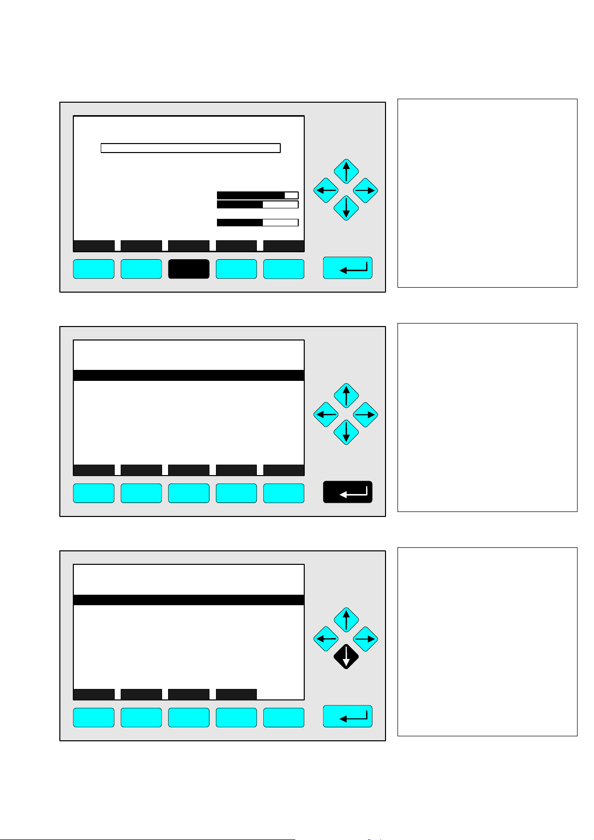
3.2. Display and operation
The measurement display and all operational steps are carried out via the LCD screen. The
keyboard itself comprises 5 function keys, 4 arrow keys and an Enter key. This handbook uses
simplified sketches to represent the user interface:
FID_WO1000001
Analyzer basic controls (calibration) & setup...
Analyzer and I/O, expert controls & setup...
System configuration and diagnostics...
Display controls...
_____________________________________________
Time & Date:
System tag:
Measure Status Channel Lock... MFG Data
F1
F2
-- Main menu --
03:11:05 August 16, 2006
F3 F4
6.28 ppm
Emerson
F5
The functions of the individual keys and the operation of the unit depend on:
the configuration of the analyzer or analyzer module
the optional modules (e.g. I/O modules) installed
the menu currently displayed.
If the power supply is interrupted, all user-specific module parameters are saved in a batteryoperated buffer.
3.3 The keyboard
FID_WO1000001
6.28 ppm THC
0 Range: 1 10
Sample pressure:
Case temperature:
Flame status:
Raw signal:
Display Status... Main... Channel BasicCal
F1
F2
ON
50
47
100000
340 hPa
51.4 C
524401
F3 F4
490
61
900000
F5
Arrow keys
↑ -key and ↓ -key:
Move up or down within a
menu;
Change or edit a setting.
← -key and → -key:
Change to previous or
next submenu or page;
Select an individual digit
or character.
Enter key
Confirm a selection;
Execute the selected
command;
Change to the selected
Function keys: Function depends on the current menu and
menu.
is displayed on the LCD screen above each key.
3- 2
NGA 2000
HAS62E-IM-SW39(1) [NGA-e (FID-Software 3.9.x)] 03/06
Page 13

Display and keyboard: 3
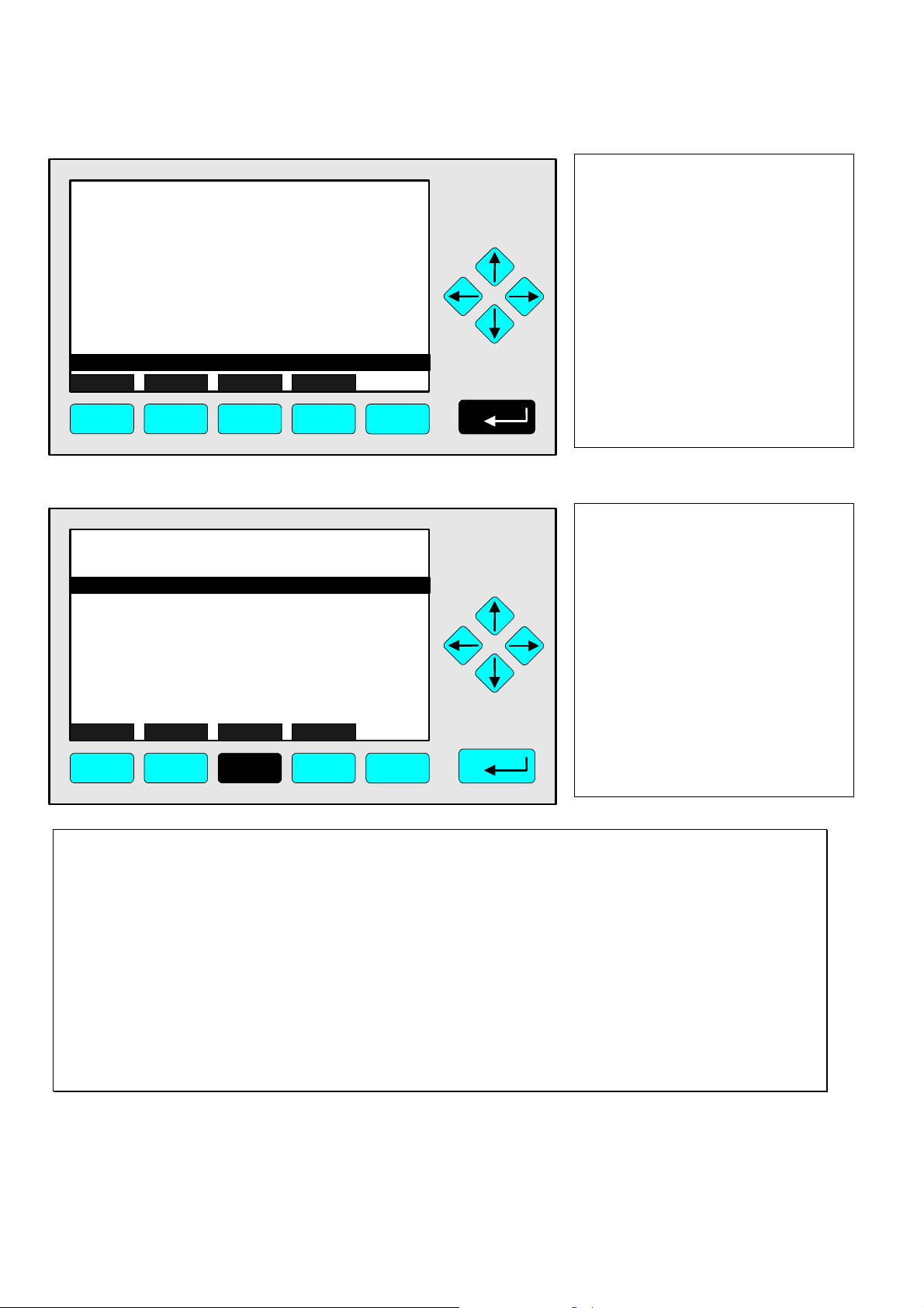
3.4 Menu items
A menu item can be selected with the ↑ -key or the ↓ -key. A selected item is shown in inverted
colours (white text against a black background). There are four different types of menu item:
Submenu...
An item ending in three dots.
Pressing the ↵ -key or the → -key accesses a submenu.
Command line !
An item ending in an exclamation point.
Pressing the ↵ -key or the → -key executes the selected function.
Parameter:
An item ending in a colon.
Displays a parameter. Some parameters can be changed, others are read-only.
If the parameter is editable, pressing the ↵ -key or the → -key puts the parameter into edit mode.
Text line
An item not ending in any of the above punctuation marks.
For information only; cannot be edited.
Text line
Parameter
Submenu
Function key labels
FID_WO1000001
Measurement range number:
Range upper limit:
Span gas concentration:
Automatic range change control:
Bypass sample flow:
Ranges with valid calibration:
Calibration status:
Flame condition:
Light flame...
HOME ESCAPE ZERO SPAN
F1
F2
Basic Controls
F3 F4
6.28 ppm
1
10.0 ppm
10.0 ppm
Disabled
0.0 ml/min
1&2&3&4
READY
ON
F5
HAS62E-IM-SW39(1) [NGA-e (FID-Software 3.9.x)] 03/06
NGA 2000
3 - 3
Page 14

FID_WO1000001
Command line
-- System Reset --
System res et !
Measure Back...
F1
Are you sure ???
F2
F3 F4
3.5 Common F-key functions
Display
Change from the single component display to the multi-component display.
Measure
Change from the main menu to the single component display.
6.28 ppm
F5
Status
Change to the “Current measurement parameters” display for the most important parameters and status
information of the FID module or the current channel.
Always F2, when this function is available.
) ch. 3.7, page 3-5.
Main
Change from the single-component display to the main menu.
HOME
Change from a submenu to the main menu.
ESCAPE or Back
Change to the previous menu.
Revert a changed, but not yet confirmed, parameter to its previous value.
Lock
Locks all levels for which security has been activated.
F4 in the main menu.
Channel
Changes to a different channel within the same menu, if more than one channel is available. Each channel is
cycled through in turn.
In the main menu the channels of all analyzers are available, in submenus only the channels of the currently
selected analyzer module.
3- 4
NGA 2000
HAS62E-IM-SW39(1) [NGA-e (FID-Software 3.9.x)] 03/06
Page 15

Display and keyboard: 3
3.6 Entering and editing parameters
The Enter key
Pressing the Enter key when an editable parameter is selected will put that parameter into
edit mode: only the value itself will be displayed white on black. Pressing the Enter key again
will save the new value.
The ↑ -key and the ↓ -key:
Depending on the value being edited, these keys will:
change the numerical value
scroll through a list of options
change a letter or other character
Numbers with more than one digit will generally be incremented or decremented. Letters are
changed one at a time.
The
←
-key and the → -key:
Select an individual digit or character. Certain numerical parameters can be edited one digit
at a time.
3.7 Current measurement parameters
Pressing F2 (“Status”) in the single component display accesses the “Current measurement
parameters” menu:
FID_WO1000001
Current measurement parameters
Status details...
Measurement range number:
Range change control:
Flame condition:
Linearization mode:
Analyzer operational state:
Analyzer alarm condition:
Alarm level reported:
Current total variable updates per second:
HOME ESCAPE MORE
F1
F2
F3 F4
6.28 ppm
1
Local
ON
DISABLED
NORMAL
NORMAL
FAILURE
25
F5
Press F3 (“More”) for
information on:
Response time
Bypass sample flow
Sample pressure
Preamp temperature
Purge control status
In this menu the status of the FID analyzer module can be checked. Pressing F3 (“MORE”)
accesses a second page; press F2 (“ESCAPE”), F4 (“MORE”) or the ← -key to return to the first
page. Pressing the Enter key with the “Status details” line selected accesses further submenus
listing error messages and many other details.
These menus are informative only. None of the settings here can be changed; this can only be
done via the “Basic controls”, “Analyzer module setup” and “Analyzer module controls” menus
(chapters 4, 5.1 and 5.2 respectively).
HAS62E-IM-SW39(1) [NGA-e (FID-Software 3.9.x)] 03/06
NGA 2000
3 - 5
Page 16

3.8 The main menu
Pressing F3 or the → -key in the single component display accesses the main menu. From this
menu all levels of the FID analyzer or analyzer module can be accessed allowing measurement,
calibration and data transfer parameters to be set.
F2
-- Main Menu --
16:35:32 June 15 2005
F3 F4
FID_WO1000001
Analyzer basic controls (calibration) & setup...
Analyzer & I/O, expert controls and setup...
System configuration and diagnostics...
Display controls...
_____________________________________________
Time & Date:
System tag:
Measure Status... Channel Lock... MFG Data
F1
6.28 ppm
Emerson
F5
See chapter 4
See chapter 5
See chapter 6
Siehe Kapitel 4
See chapter 7
To set: ch. 6.3, page 6-29
Factory setting
F1: Change to the single component display of the current channel
F2: Change to the “Current measurement parameters” menu ) ch. 3.7, page 3-5
F3: Change to a different channel ) ch. 3.5, page 3-4
F4: Lock level(s) using security codes ) ch. 6.4, page 6-31
F5: Change to the “Manufacturing data” menu ) below
Pressing F5 accesses submenus in which important information about the control module and
the analyzer module can be found:
FID_WO1000001
Control module manufacturing data...
Analyzer module manufacturing data...
Measure <<< Back... >>>
F1
-- Manufacturing Data --
F2
F3 F4
6.28 ppm
F5
3- 6
NGA 2000
HAS62E-IM-SW39(1) [NGA-e (FID-Software 3.9.x)] 03/06
Page 17

3.8.1 Control module manufacturing data
FID_WO1000001
Control module manufacturing data...
Analyzer module manufacturing data...
-- Manufacturing Data --
6.28 ppm
FID_WO1000001
Display and keyboard: 3
-- Control Module Manufacturing Data --
Emerson Process Management
FAX. (+49) 6055 884 - 209
Copyright (c) 2005
GmbH & Co. OHG
Industriestrasse 1
D-63594 Hasselroth
Tel (+49) 6055 884 - 0
6.28 ppm
Measure <<< Back... >>>
F1
F2
F3 F4
F5
Measure Back... More
F1
FID_WO1000001
-- Control Module Version Information --
Serial number:
Manufacturing date:
Hardware revision:
Software revision:
Revision date:
Revision time:
Phrase dictionary version:
Language:
Measure Back...
F1
F3 F4
F2
ACV02 R:3.9.0 D:Jul 17 2003
F3 F4
F2
F5
6.28 ppm
CM1
20.05.2004
3.9.4 / P017
Nov 11 2005
12:01:04
P017 / 01 / 00
English
F5
HAS62E-IM-SW39(1) [NGA-e (FID-Software 3.9.x)] 03/06
NGA 2000
3 - 7
Page 18

3.8.2 Analyzer module manufacturing data
FID_WO1000001
Control module manufacturing data...
Analyzer module manufacturing data...
Measure <<< Back... >>>
F1
-- Manufacturing Data --
F3 F4
F2
FID_WO1000001
-- Analyzer Module Manufacturing Data --
Emerson Process Management
FAX. (+49) 6055 884 - 209
Copyright (c) 2005
GmbH & Co. OHG
Industriestrasse 1
D-63594 Hasselroth
Tel. (+49) 6055 884 - 0
6.28 ppm
F5
6.28 ppm
FID_WO1000001
More...
Minimum range:
Maximum range:
Measured gas:
Capillary:
Flow sensor:
HOME ESCAPE
F1
FID_WO1000001
Serial number:
Manufacturing date:
Hardware revision:
Software revision:
Revision date:
Revision time:
Analyzer manufacturing data
F2
-- Analyzer Module Version Information --
13.5 ml/min @ 5psig
F3 F4
02:28:10 February 01, 2005
3.9.4 / P017
Nov 11 2005
6.28 ppm
4.0 ppm
10000 ppm
THC
Present
F5
6.28 ppm
FID1
0.5
12:33:56
Measure Back... More...
F1
F2
F3 F4
F5
Measure Back...
F1
F3 F4
F2
F5
3- 8
NGA 2000
HAS62E-IM-SW39(1) [NGA-e (FID-Software 3.9.x)] 03/06
Page 19

Basic controls: 4
Introduction
Chapter 4 describes the most important basic functions which are needed to configure a FID
analyzer module with an NGA front panel.
The following basic functions are available:
Measurement ) Chapter 4.1, page 4-3ff
Calibration ) Chapter 4.2, page 4-21ff
The basic settings are fully explained and illustrated step by step. The two-column layout shows
the user interface of the NGA front panel on the left. This enables the user to follow each step
and compare the illustrations with the analyzer display screen. On the right, each step is briefly
described. Each sub-chapter begins and ends with a single component display. The keys to be
pressed for each step are highlighted in black.
See the example on the next page.
HAS62E-IM-SW39(1) [NGA-e (FID-Software 3.9.x)] 03/06
NGA 2000
4 - 1
Page 20

Example: Changing from the single component display to the main menu
⇒ The first illustration shows the initial situation
⇒ Pressing key F3 changes the display to that in the second illustration
1. Change to the main menu
FID_WO1000001
6.28 ppm THC
0 Range: 1 10
Sample pressure:
Case temperature:
Flame status:
Raw signal:
Display Status... Main... Channel BasicCal
340 hPa
51.4 C
ON
524401
50
47
100000
490
61
900000
Press F3 or the → -key.
F1
F2
F3 F4
FID_WO1000001
Analyzer basic controls (calibration) & setup...
Analyzer & I/O, expert controls and setup...
System configuration and diagnostics...
Display controls...
_____________________________________________
Time & Date:
System tag:
Measure Status... Channel Lock... MFG Data
F1
F2
-- Main Menu --
16:35:32 June 15 2005
F3 F4
F5
6.28 ppm
Emerson
F5
2. Any further instructions
follow, e.g.:
Change to the basic controls
Press the ↵ -key or the → -key.
4- 2
NGA 2000
HAS62E-IM-SW39(1) [NGA-e (FID-Software 3.9.x)] 03/06
Page 21

This subchapter describes the following functions:
Changing channels
) Chapter 4.1.1, page 4-5
Changing the order of the multi-component display
) Chapter 4.1.2, page 4-7
Changing the measurement range
) Chapter 4.1.3, page 4-9
Automatic range change
) Chapter 4.1.4, page 4-13
Lighting the flame
) Chapter 4.1.5, page 4-17
Basic controls: 4.1
Measurement
Chapters 4.1.1 and 4.1.2 are only relevant to systems with more than one
measurement channel.
HAS62E-IM-SW39(1) [NGA-e (FID-Software 3.9.x)] 03/06
NGA 2000
4 - 3
Page 22

4- 4
NGA 2000
HAS62E-IM-SW39(1) [NGA-e (FID-Software 3.9.x)] 03/06
Page 23

FID_WO1000001
6.28 ppm THC
0 Range: 1 10
Sample pressure:
Case temperature:
Flame status:
Raw signal:
Display Status... Main... Channel BasicCal
ON
50
47
100000
340 hPa
51.4 C
524401
490
61
900000
Basic controls: 4.1.1
Changing channels
1. Change to the multicomponent display
Press F1.
Note: The multi-component
display can be reached from
any single component display
by this method.
F1
F2
F3 F4
6.28
45.00
333.0
150.0
20.00
Select Status... Tags Off
F1 F2 F3 F4 F5
MLT25/CH1/R2
MLT25/CH2/R2
MLT25/CH3/R2
MLT25/CH4/R2
FID
ppm THC
ppm CO
ppm SO2
ppm NO
%O2
0
0
0
0
0
[1]
[2]
[3]
[4]
[5]
F5
10
10
10
10
10
LCDReset
2. Activate select function
Press F1 or the ↓ -key.
Note: If there are no other
channels connected to the
FID, only the bargraph of the
FID itself will be displayed. A
change of channels will then
not be possible.
6.28
>
45.00
333.0
150.0
20.00
Select Status... Tags Off
F1
MLT25/CH1/R2
MLT25/CH2/R2
MLT25/CH3/R2
MLT25/CH4/R2
F2 F3 F4 F5
FID
ppm THC
ppm CO
ppm SO2
ppm NO
%O2
HAS62E-IM-SW39(1) [NGA-e (FID-Software 3.9.x)] 03/06
0
0
0
0
0
[1]
[2]
[3]
[4]
[5]
10
10
10
10
10
LCDReset
NGA 2000
2. Select a channel
Press the ↑ or ↓ -key until the
> symbol appears in the line
you wish to select.
4 - 5
Page 24

3. Return to the single
6.28
45.00
>
333.0
150.0
20.00
FID
ppm THC
MLT25/CH1/R2
ppm CO
MLT25/CH2/R2
ppm SO2
MLT25/CH3/R2
ppm NO
MLT25/CH4/R2
%O2
0
0
0
0
0
[1]
[2]
[3]
[4]
[5]
10
10
10
10
10
component display
Press F1.
Select Status... Tags Off
F1
F2 F3 F4 F5
FID_WO1000001
45.28 ppm CO
0 Range: 2 250
Sample pressure:
Case temperature:
Flame status:
Raw signal:
Display Status... Main... Channel BasicCal
F1
F2
ON
50
47
100000
340 hPa
51.4 C
524401
F3 F4
LCDReset
4. The single component
display after selecting a new
channel.
490
61
900000
F5
4- 6
NGA 2000
HAS62E-IM-SW39(1) [NGA-e (FID-Software 3.9.x)] 03/06
Page 25

Changing the order of the multi-component display
FID_WO1000001
6.28 ppm THC
0 Range: 1 10
Sample pressure:
Case temperature:
Flame status:
Raw signal:
Display Status... Main... Channel BasicCal
ON
50
47
100000
340 hPa
51.4 C
524401
Basic controls: 4.1.2
1. Change to the multicomponent display
Press F1.
490
61
900000
F1
F2
6.28
45.00
333.0
150.0
20.00
Select Status... Tags Off
F1
ppm THC
MLT25/CH1/R2
ppm CO
MLT25/CH2/R2
ppm SO2
MLT25/CH3/R2
ppm NO
MLT25/CH4/R2
F2 F3 F4 F5
F3 F4
FID
0
0
0
0
0
%O2
[1]
[2]
[3]
[4]
[5]
F5
10
10
10
10
10
LCDReset
2. Activate select function
Press F1 or the ↓ -key.
Note: If no other channels are
connected to the FID, only the
bargraph of the FID itself will
be displayed, and steps to
change the order are
superfluous.
6.28
>
45.00
333.0
150.0
20.00
Select Status... Tags Off
F1
MLT25/CH1/R2
MLT25/CH2/R2
MLT25/CH3/R2
MLT25/CH4/R2
F2 F3 F4 F5
FID
ppm THC
ppm CO
ppm SO2
ppm NO
%O2
HAS62E-IM-SW39(1) [NGA-e (FID-Software 3.9.x)] 03/06
0
0
0
0
0
[1]
[2]
[3]
[4]
[5]
10
10
10
10
10
LCDReset
NGA 2000
2. Select a channel to appear
in the first line
Press the ↑ or ↓ -key until the
> symbol is next to the
appropriate bargraph.
Example: MLT channel 2
) is to be displayed in the
(SO
2
first line.
4 - 7
Page 26

3. Set the selected bargraph
6.28
45.00
333.0
>
150.0
20.00
FID
ppm THC
MLT25/CH1/R2
ppm CO
MLT25/CH2/R2
ppm SO2
MLT25/CH3/R2
ppm NO
MLT25/CH4/R2
%O2
0
0
0
0
0
[1]
[2]
[3]
[4]
[5]
10
10
10
10
10
to the first line
Press the ↵ -key.
Select... Display Tags Off
F1
F2 F3 F4 F5
333.0
6.28
45.00
150.0
20.00
Select Status... Tags Off
F1
MLT25/CH2/R2
ppm SO2
ppm THC
MLT25/CH1/R2
MLT25/CH3/R2
MLT25/CH4/R2
F2 F3 F4 F5
FID
ppm CO
ppm NO
%O2
0
0
0
0
0
[1]
[2]
[3]
[4]
[5]
LCDReset
10
10
10
10
10
LCDReset
4. The multi-component
display after setting the
order of bargraphs
It is now possible to select any single component display. See chapter 4.1.1 for
further instructions.
4- 8
NGA 2000
HAS62E-IM-SW39(1) [NGA-e (FID-Software 3.9.x)] 03/06
Page 27

FID_WO1000001
6.28 ppm THC
51.4 C
ON
50
47
100000
0 Range: 1 10
Sample pressure:
Case temperature:
Flame status:
Raw signal:
Display Status... Main... Channel BasicCal
340 hPa
524401
Basic controls: 4.1.3
Changing the measurement range
1. Change to the main menu
Press F3 or the → -key.
490
61
900000
F1
F2
F3 F4
F2
-- Main Menu --
16:35:32 June 15 2005
F3 F4
FID_WO1000001
Analyzer basic controls (calibration) & setup...
Analyzer & I/O, expert controls and setup...
System configuration and di ag nost ic s. ..
Display controls...
_____________________________________________
Time & Date:
System tag:
Measure Status... Channel Lock... MFG Data
F1
FID_WO1000001
Measurement range number:
Range upper limit:
Span gas concentration:
Automatic range change control:
Bypass sample flow:
Ranges with valid calibration:
Calibration status:
Flame condition:
Light flame...
HOME ESCAPE ZERO SPAN
Basic Controls
F5
6.28 ppm
Emerson
F5
6.28 ppm
10.0 ppm
10.0 ppm
Disabled
0.0 ml/min
1&2&3&4
READY
ON
2. Change to the basic
controls
Press the ↵ -key or the
→ -key.
3. Select “Measurement
range number”
1
Press the ↵ -key or the
→ -key.
F1
F2
F3 F4
HAS62E-IM-SW39(1) [NGA-e (FID-Software 3.9.x)] 03/06
F5
NGA 2000
4 - 9
Page 28

FID_WO1000001
Basic Controls
Measurement range number:
Range upper limit:
Span gas concentration:
Automatic range change control:
Bypass sample flow:
Ranges with valid calibration:
Calibration status:
Flame condition:
Light flame...
Back...
6.28 ppm
10.0 ppm
10.0 ppm
Disabled
0.0 ml/min
1&2&3&4
READY
ON
4. Set the new range number
1
Press the ↑-key or the ↓ -key
until the required range
number appears.
Example: Changing from
range 1 to range 2.
F1
F2
F3 F4
FID_WO1000001
Measurement range number:
Range upper limit:
Span gas concentration:
Automatic range change control:
Bypass sample flow:
Ranges with valid calibration:
Calibration status:
Flame condition:
Light flame...
F1
F2
Basic Controls
Back...
F3 F4
FID_WO1000001
Measurement range number:
Range upper limit:
Span gas concentration:
Automatic range change control:
Bypass sample flow:
Ranges with valid calibration:
Calibration status:
Flame condition:
Light flame...
HOME ESCAPE ZERO SPAN
Basic Controls
F5
6.28 ppm
10.0 ppm
10.0 ppm
Disabled
0.0 ml/min
1&2&3&4
READY
ON
F5
6.28 ppm
25.0 ppm
10.0 ppm
Disabled
0.0 ml/min
1&2&3&4
READY
ON
5. Confirm range number
2
Press the ↵ -key.
Note: To cancel the change
and return to the previous
value, press F2.
6 Change to the main menu
2
Press the ← -key or F1.
Note: The range upper limit
(2nd line) automatically
changes to the value
previously set for the selected
range.
F1
F2
F3 F4
F5
4- 10
NGA 2000
HAS62E-IM-SW39(1) [NGA-e (FID-Software 3.9.x)] 03/06
Page 29

FID_WO1000001
Analyzer basic controls (calibration) & setup...
Analyzer & I/O, expert controls and setup...
System configuration and di ag nost ic s. ..
Display controls...
_____________________________________________
Time & Date:
System tag:
Measure Status... Channel Lock... MFG Data
-- Main Menu --
16:35:44 June 15 2005
6.28 ppm
Emerson
Basic controls: 4.1.3
Changing the measurement range
7. Change to the single
component display
Press F1.
F1
F2
F3 F4
F2
ON
50
47
100000
340 hPa
51.4 C
524401
F3 F4
FID_WO1000001
6.28 ppm THC
0 Range: 2 25
Sample pressure:
Case temperature:
Flame:
Raw signal:
Display Status... Main... Channel BasicCal
F1
HAS62E-IM-SW39(1) [NGA-e (FID-Software 3.9.x)] 03/06
F5
900000
F5
490
61
NGA 2000
8. The single component
display showing the new
measurement range
4 - 11
Page 30

4- 12
NGA 2000
HAS62E-IM-SW39(1) [NGA-e (FID-Software 3.9.x)] 03/06
Page 31

FID_WO1000001
6.28 ppm THC
51.4 C
ON
50
47
100000
0 Range: 1 10
Sample pressure:
Case temperature:
Flame status:
Raw signal:
Display Status... Main... Channel BasicCal
340 hPa
524401
Basic controls: 4.1.4
Automatic range change
1. Change to the main menu
Press F3 or the → -key.
490
61
900000
F1
F2
F3 F4
F2
-- Main Menu --
16:35:32 June 15 2005
F3 F4
FID_WO1000001
Analyzer basic controls (calibration) & setup...
Analyzer & I/O, expert controls and setup...
System configuration and di ag nost ic s. ..
Display controls...
_____________________________________________
Time & Date:
System tag:
Measure Status... Channel Lock... MFG Data
F1
FID_WO1000001
Measurement range number:
Range upper limit:
Span gas concentration:
Automatic range change control:
Bypass sample flow:
Ranges with valid calibration:
Calibration status:
Flame condition:
Light flame...
HOME ESCAPE ZERO SPAN
Basic Controls
F5
6.28 ppm
Emerson
F5
6.28 ppm
10.0 ppm
10.0 ppm
Disabled
0.0 ml/min
1&2&3&4
READY
ON
2. Change to the basic
controls
Press the ↵ -key or the
→ -key.
3. Select menu item
“Automatic range change
control”
1
Press the ↑-key or the ↓ -key
until the line “Automatic range
change control” is displayed
against a black background.
F1
F2
F3 F4
HAS62E-IM-SW39(1) [NGA-e (FID-Software 3.9.x)] 03/06
F5
NGA 2000
4 - 13
Page 32

FID_WO1000001
Basic Controls
Measurement range number:
Range upper limit:
Span gas concentration:
Automatic range change control:
Bypass sample flow:
Ranges with valid calibration:
Calibration status:
Flame condition:
Light flame...
HOME ESCAPE ZERO SPAN
6.28 ppm
10.0 ppm
10.0 ppm
Disabled
0.0 ml/min
1&2&3&4
READY
ON
4. Select the item
1
Press the ↵ -key or the
→ -key.
F1
F2
F3 F4
FID_WO1000001
Measurement range number:
Range upper limit:
Span gas concentration:
Automatic range change control:
Bypass-Durchfluss:
Messbereiche mit gültiger Kalibrierung:
Kalibrierart:
Flammenzustand:
Flamme zünden...
F1
F2
Basic Controls
Back...
F3 F4
F5
6.28 ppm
10.0 ppm
10.0 ppm
Disabled
0.0 ml/min
1&2&3&4
READY
ON
F5
5. Set the required value
1
Press the ↑-key or the ↓ -key
until the required value is
displayed.
The following settings are available:
Disabled Automatic range change control is switched off.
Enabled:SLC On The new switch level is automatically calculated (see
ch. 5.1.4.4, page 5-27).
Enabled: SLC Off The new switch level is not automatically calculated.
4- 14
NGA 2000
HAS62E-IM-SW39(1) [NGA-e (FID-Software 3.9.x)] 03/06
Page 33

FID_WO1000001
Basic Controls
Measurement range number:
Range upper limit:
Span gas concentration:
Automatic range change control:
Bypass sample flow:
Ranges with valid cali bration:
Calibration status:
Flamen condition:
Light flame...
Back...
6.28 ppm
10.0 ppm
10.0 ppm
Enabled:SLC Off
0.0 ml/min
1&2&3&4
READY
ON
Basic controls: 4.1.4
Automatic range change
6. Confirm new setting
1
Press the ↵ -key.
Note: To cancel the change
and return to the previous
value, press F2.
F1
F2
F3 F4
FID_WO1000001
Measurement range number:
Range upper limit:
Span gas concentration:
Automatic range change control:
Bypass sample flow:
Ranges with valid calibration:
Calibration status:
Flame condition:
Light flame...
HOME ESCAPE ZERO SPAN
F1
F2
Basic Controls
F3 F4
F5
6.28 ppm
10.0 ppm
10.0 ppm
Enabled:SLC Off
0.0 ml/min
1&2&3&4
READY
ON
F5
7. Change to the main menu
1
Press the ← -key or F1.
FID_WO1000001
Analyzer basic controls (calibration) & setup...
Analyzer and I/O, expert controls & setup...
System configuration and di ag nost ic s. ..
Display controls...
_____________________________________________
Time & Date:
System tag:
Measure Status... Channel Lock... MFG Data
F1
F2
-- Main Menu --
16:36:05 June 15, 2005
F3 F4
HAS62E-IM-SW39(1) [NGA-e (FID-Software 3.9.x)] 03/06
6.28 ppm
Emerson
F5
NGA 2000
8. Change to the single
component display
Press F1.
4 - 15
Page 34

FID_WO1000001
6.28 ppm THC
0 Range: 1 10
Sample pressure:
Case temperature:
Flame status:
Raw signal:
Display Status... Main... Channel BasicCal
340 hPa
51.4 C
ON
524401
50
47
100000
9. The single component
display after completion of
the preceding steps
490
61
900000
F1
F2
F3 F4
F5
4- 16
NGA 2000
HAS62E-IM-SW39(1) [NGA-e (FID-Software 3.9.x)] 03/06
Page 35
FID_WO1000001
-4.76 ppm THC
51.4 C
OFF
50
47
100000
0 Range: 1 10
Sample pressure:
Case temperature:
Flame status:
Raw signal:
Display Status... Main... Channel BasicCal
F1
F2
340 hPa
524401
F3 F4
FID_WO1000001
Analyzer basic controls (calibration) & setup...
Analyzer and I/O, expert controls & setup...
System configuration and di ag nost ic s. ..
Display controls...
_____________________________________________
Time & Date:
System tag:
Measure Status... Channel Lock... MFG Data
-- Main Menu --
16:02:09 June 15, 2005
490
61
900000
F5
-4.76 ppm
Emerson
Basic controls: 4.1.5
Lighting the flame
1. Change to the main menu
Press F3 or the → -key.
Note: When the flame is unlit,
the FID will show an obviously
nonsensical measurement.
The line “Flame status” shows
the value “OFF”. In order to
use the FID, the flame must be
lit.
2. Change to the basic
controls
Press the ↵ -key or the
→ -key.
F1
F2
F3 F4
FID_WO1000001
Measurement range number:
Range upper limit:
Span gas concentration:
Automatic range change control:
Bypass sample flow:
Ranges with valid calibration:
Calibration status:
Flame condition:
Light flame...
HOME ESCAPE ZERO SPAN
F1
F2
Basic Controls
F3 F4
F5
-4.76 ppm
10.0 ppm
10.0 ppm
Disabled
0.0 ml/min
1&2&3&4
Bereit
OFF
F5
3. Select menu item “Light
flame”
1
Press the ↑-key or the ↓ -key
until the line “Light flame” is
displayed against a black
background.
HAS62E-IM-SW39(1) [NGA-e (FID-Software 3.9.x)] 03/06
NGA 2000
4 - 17
Page 36
FID_WO1000001
Basic Controls
Measurement range number:
Range upper limit:
Span gas concentration:
Automatic range change control:
Bypass sample flow:
Ranges with valid calibration:
Calibration status:
Flame condition:
Light flame...
HOME ESCAPE ZERO SPAN
-4.76 ppm
10.0 ppm
10.0 ppm
Disabled
0.0 ml/min
1&2&3&4
READY
OFF
4. Select the item
1
Press the ↵ -key or the
→ -key.
F1
F2
F3 F4
F5
FID_WO1000001
Flame condition:
Auto-ignition:
Ignition system enable:
Number of ignition attempts so far:
Time on this cycle - secs:
Fuel supply pressure:
Burner air pressure:
Sample pressure:
Purge gas pressure:
Flame temperature:
Status:
HOME ABORT LIGHT ENRICH
F1
F2
Light Flame
AIR PRESSURE TOO LOW
F3 F4
-4.76 ppm
OFF
ENABLED
ON
0
0
1602 hPa
1042 hPa
341 hPa
691 hPa
51.0 C
F5
5. Check values and light
flame
If the values shown are within
certain limits, the flame can be
lit.
Press F3.
The flame can only be lit when the system has been successfully purged. The
following conditions must be met for the purge cycle to commence:
Purge gas pressure no less than 680 hPa
Purge gas flow between approx. 16 and 18 l/min
Small difference in pressure outside and inside the case
Before the flame can be ignited, the system must have been successfully purged. In
addition, the following conditions must be met:
Burner air pressure approx. 1040 hPa
Sample gas pressure approx. 340 or 140 hPa, depending on the type of capilliaries
4- 18
NGA 2000
HAS62E-IM-SW39(1) [NGA-e (FID-Software 3.9.x)] 03/06
Page 37

FID_WO1000001
Light Flame
Flame condition:
Auto-ignition:
Ignition system enable:
Number of ignition attempts so far:
Time on this cycle - secs:
Fuel supply pressure:
Burner air pressure:
Sample pressure:
Purge gas pressure:
Flame temperature:
Status:
ABORT
-4.76 ppm
OFF
ENABLED
ON
15
1602 hPa
1042 hPa
341 hPa
691 hPa
51.0 C
AIR PRESSURE TOO LOW
Basic controls: 4.1.5
Lighting the flame
6. Burner air is enriched
The line “Time on this cycle”
0
starts counting the seconds.
Note: To abort the procedure,
press F2.
F1
F2
FID_WO1000001
Flame condition:
Auto-ignition:
Ignition system enable:
Number of ignition attempts so far:
Time on this cycle - secs:
Fuel supply pressure:
Burner air pressure:
Sample pressure:
Purge gas pressure:
Flame temperature:
Status:
ABORT
F1
F2
Light Flame
F3 F4
PARAMETERS NORMAL
F3 F4
F5
-4.76 ppm
OFF
ENABLED
ON
72
1602 hPa
1042 hPa
341 hPa
691 hPa
176 C
F5
7. Flame is ignited
The flame temperature rises. If
0
it remains steady at more than
115°C, the flame has been
successfully lit.
The FID can be configured to start a new cycle automatically after a failed ignition
attempt. The maximum number of attempts can be set in the “Auto ignition
parameters” menu (see chapter 6.1.2.6, page 6-19).
By default the FID makes up to 3 attempts.
HAS62E-IM-SW39(1) [NGA-e (FID-Software 3.9.x)] 03/06
NGA 2000
4 - 19
Page 38

FID_WO1000001
Light Flame
Flame condition:
Auto-ignition:
Ignition system enable:
Number of ignition attempts so far:
Time on this cycle - secs:
Fuel supply pressure:
Burner air pressure:
Sample pressure:
Purge gas pressure:
Flame temperature:
Status:
HOME ABORT LIGHT ENRICH
6.28 ppm
ON
ENABLED
ON
81
1602 hPa
1042 hPa
341 hPa
691 hPa
176 C
PARAMETERS NORMAL
8. Change to the main menu
Press the ← -key or F1.
0
F1
F2
F3 F4
F2
-- Main Menu --
16:03:45 June 15, 2005
F3 F4
FID_WO1000001
Analyzer basic controls (calibration) & setup...
Analyzer and I/O, expert controls & setup...
System configuration and diagnostics...
Display controls...
_____________________________________________
Time & Date:
System tag:
Measure Status... Channel Lock... MFG Data
F1
FID_WO1000001
6.28 ppm THC
0 Range: 1 10
Sample pressure:
Case temperature:
Flame status:
Raw signal:
Display Status... Main... Channel BasicCal
ON
50
47
100000
340 hPa
51.4 C
524401
F5
6.28 ppm
Emerson
F5
490
61
900000
9. Change to the single
component display
Press F1.
10. The single component
display after lighting the
flame
F1
F2
F3 F4
F5
4- 20
NGA 2000
HAS62E-IM-SW39(1) [NGA-e (FID-Software 3.9.x)] 03/06
Page 39

Basic controls: 4.2
Calibration
This subchapter describes the following functions:
Zeroing
) Chapter 4.2.1, page 4-23
Spanning
) Chapter 4.2.2, page 4-27
Before the FID can be used, each measurement range must be successfully zeroed
and spanned. Zeroing should be performed first.
HAS62E-IM-SW39(1) [NGA-e (FID-Software 3.9.x)] 03/06
NGA 2000
4 - 21
Page 40

4- 22
NGA 2000
HAS62E-IM-SW39(1) [NGA-e (FID-Software 3.9.x)] 03/06
Page 41

FID_WO1000001
6.28 ppm THC
51.4 C
ON
50
47
100000
0 Range: 1 10
Sample pressure:
Case temperature:
Flame status:
Raw signal:
Display Status... Main... Channel BasicCal
340 hPa
524401
Basic controls: 4.2.1
Zeroing
1. Change to the main menu
Press F3 or the → -key.
490
61
900000
F1
F2
F3 F4
F2
-- Main Menu --
16:35:32 June 15 2005
F3 F4
FID_WO1000001
Analyzer basic controls (calibration) & setup...
Analyzer & I/O, expert controls and setup...
System configuration and di ag nost ic s. ..
Display controls...
_____________________________________________
Time & Date:
System tag:
Measure Status... Channel Lock... MFG Data
F1
FID_WO1000001
Measurement range number:
Range upper limit:
Span gas concentration:
Automatic range change control:
Bypass sample flow:
Ranges with valid calibration:
Calibration status:
Flame condition:
Light flame...
HOME ESCAPE ZERO SPAN
Basic Controls
F5
6.28 ppm
Emerson
F5
6.28 ppm
10.0 ppm
10.0 ppm
Disabled
0.0 ml/min
1&2&3&4
READY
ON
2. Change to the basic
controls
Press the ↵ -key or the
→ -key.
3. Change to the “Analyzer
zero” menu
1
Press F3.
F1
F2
F3 F4
HAS62E-IM-SW39(1) [NGA-e (FID-Software 3.9.x)] 03/06
F5
NGA 2000
4 - 23
Page 42

FID_WO1000001
Analyzer zero
Are you sure?
You must have zero gas flowing through the analyzer.
Calibration time:
Measurement range number:
Calibration status:
Error message for last zero:
HOME ESCAPE ZERO Prüf-Kal
6.28 ppm
0 s
READY
CAL OK
4. Commence zeroing.
Press F3.
Note: Pressing F2 will take you
1
back to the “Basic Controls”
menu.
F1
F2
F3 F4
F5
Before calibration can begin, the following conditions must be met:
Zero gas must flow through the analyzer for a sufficient period of time.
The measured value must be stable.
Each range can be zeroed separately, or all together. This preference can be set in
the “Calibration parameters” menu (see chapter 5.1.2, page 5-13).
FID_WO1000001
Are you sure?
You must have zero gas flowing through the analyzer.
Calibration time:
Measurement range number:
Calibration status:
Error message for last zero:
Analyzer zero
ZEROING - WAIT
3.02 ppm
CAL OK
10 s
1
5. Zeroing in progress
Note: To abort the procedure,
press F2.
Abort Prüf-Kal
F1
F2
F3 F4
F5
4- 24
NGA 2000
HAS62E-IM-SW39(1) [NGA-e (FID-Software 3.9.x)] 03/06
Page 43

FID_WO1000001
Are you sure?
You must have zero gas flowing through the analyzer.
Calibration time:
Measurement range number:
Calibration status:
Error message for last zero:
HOME ESCAPE ZERO Prüf-Kal
F1
F2
Analyzer zero
F3 F4
0.05 ppm
17 s
READY
CAL OK
F5
Basic controls: 4.2.1
Zeroing
6. Change to the main menu
Press F1.
Note: To span the analyzer
1
directly after zeroing, press F2
to return to the “Basic
Controls” menu and follow the
instructions in chapter 4.2.2
from step 3 onwards.
FID_WO1000001
Analyzer basic controls (calibration) & setup...
Analyzer and I/O, expert controls & setup...
System configuration and di ag nost ic s. ..
Display controls...
_____________________________________________
Time & Date:
System tag:
Measure Status... Channel Lock... MFG Data
F1
F2
-- Main Menu --
16:40:38 June 15, 2005
F3 F4
FID_WO1000001
0.02 ppm THC
0 Range: 1 10
Sample pressure:
Case temperature:
Flame status:
Raw signal:
Display Status... Main... Channel BasicCal
ON
50
47
100000
340 hPa
51.4 C
524401
0.02 ppm
Emerson
F5
490
61
900000
7. Change to the single
component display
Press F1.
8. The single component
display after zeroing
F1
F2
F3 F4
HAS62E-IM-SW39(1) [NGA-e (FID-Software 3.9.x)] 03/06
F5
NGA 2000
4 - 25
Page 44

4- 26
NGA 2000
HAS62E-IM-SW39(1) [NGA-e (FID-Software 3.9.x)] 03/06
Page 45

FID_WO1000001
6.28 ppm THC
51.4 C
ON
50
47
100000
0 Range: 1 10
Sample pressure:
Case temperature:
Flame status:
Raw signal:
Display Status... Main... Channel BasicCal
340 hPa
524401
Basic controls: 4.2.2
Spanning
1. Change to the main menu
Press F3 or the → -key.
490
61
900000
F1
F2
F3 F4
F2
-- Main Menu --
16:35:32 June 15 2005
F3 F4
FID_WO1000001
Analyzer basic controls (calibration) & setup...
Analyzer & I/O, expert controls and setup...
System configuration and di ag nost ic s. ..
Display controls...
_____________________________________________
Time & Date:
System tag:
Measure Status... Channel Lock... MFG Data
F1
FID_WO1000001
Measurement range number:
Range upper limit:
Span gas concentration:
Automatic range change control:
Bypass sample flow:
Ranges with valid calibration:
Calibration status:
Flame condition:
Light flame...
HOME ESCAPE ZERO SPAN
Basic Controls
F5
6.28 ppm
Emerson
F5
6.28 ppm
10.0 ppm
10.0 ppm
Disabled
0.0 ml/min
1&2&3&4
READY
ON
2. Change to the basic
controls
Press the ↵ -key or the
→ -key.
3. Change to the “Analyzer
span” menu
1
Press F4.
F1
F2
F3 F4
HAS62E-IM-SW39(1) [NGA-e (FID-Software 3.9.x)] 03/06
F5
NGA 2000
4 - 27
Page 46

FID_WO1000001
Analyzer span
Are you sure?
You must have span gas flowing through the analyzer.
Calibration time:
Measurement range number:
Calibration status:
Error message for last span:
HOME ESCAPE SPAN
6.28 ppm
0 s
READY
CAL OK
4. Commence spanning
Press F4.
Note: Pressing F2 will take you
1
back to the “Basic Controls”
menu.
F1
F2
F3 F4
F5
Before calibration can begin, the following conditions must be met:
Span gas must flow through the analyzer for a sufficient period of time.
The measured value must be stable.
Each range can be spanned separately, or all together. This preference can be set in
the “Calibration parameters” menu (see chapter 5.1.2, page 5-13).
If it is not possible to calibrate all ranges with the same span gas, the ranges must be
calibrated separately.
The span gas concentration must be between 10% and 110% of the upper limit of the
current range. See chapter 5.1.1, page 5-5.
FID_WO1000001
Are you sure?
You must have span gas flowing through the analyzer.
Calibration time:
Measurement range number:
Calibration status:
Error message for last span:
Analyzer span
SPANNING - WAIT
8.14 ppm
10 s
CAL OK
1
5. Spanning in progress
Note: To abort the procedure,
press F2.
Abort
F1
F2
F3 F4
F5
4- 28
NGA 2000
HAS62E-IM-SW39(1) [NGA-e (FID-Software 3.9.x)] 03/06
Page 47

FID_WO1000001
Are you sure?
You must have span gas flowing through the analyzer.
Calibration time:
Measurement range number:
Calibration status:
Error message for last span:
HOME ESCAPE SPAN
Analyzer span
9.76 ppm
18 s
READY
CAL OK
Basic controls: 4.2.2
Spanning
6. Change to the main menu
Press F1.
1
F1
F2
F3 F4
FID_WO1000001
Analyzer basic controls (calibration) & setup...
Analyzer and I/O, expert controls & setup...
System configuration and di ag nost ic s. ..
Display controls...
_____________________________________________
Time & Date:
System tag:
Measure Status... Channel Lock... MFG Data
F1
F2
-- Main Menu --
16:42:38 June 15, 2005
F3 F4
F5
9.76 ppm
Emerson
F5
7. Change to the single
component display
Press F1.
FID_WO1000001
9.76 ppm THC
51.4 C
ON
50
47
100000
0 Range: 1 10
Sample pressure:
Case temperature:
Flame status:
Raw signal:
Display Status... Main... Channel BasicCal
F1
F2
340 hPa
524401
F3 F4
HAS62E-IM-SW39(1) [NGA-e (FID-Software 3.9.x)] 03/06
900000
F5
490
61
NGA 2000
8. The single component
display after spanning
4 - 29
Page 48

4- 30
NGA 2000
HAS62E-IM-SW39(1) [NGA-e (FID-Software 3.9.x)] 03/06
Page 49

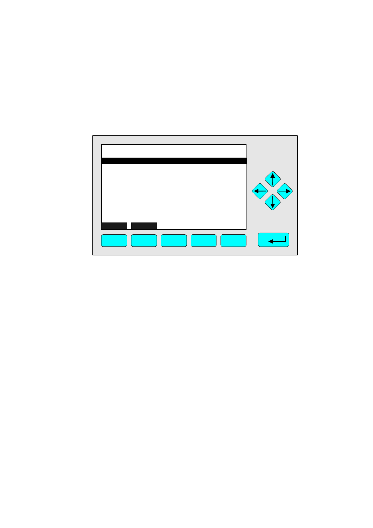
Analyzer and I/O, expert controls & setup: 5
Introduction
Main menu
↓
Analyzer and I/O, expert controls & setup
↓
FID_WO1000001
-- Analyzer and I/O, Expert Controls & Setup --
Analyzer module controls...
System & network I/O module controls...
Analyzer module setup...
System & network I/O module setup...
(Note: Controls & setup are identical for MLT/TFID)
Measure Channel Back...
F1
F2
F3 F4
6.28 ppm
F5
From the main menu, pressing the ↵ -key or the → -key in the line “Analyzer and I/O, expert
controls & setup” accesses this menu, from which several submenus lead to options for setting
measurement and calibration parameters for the analyzer or analyzer modules, as well as for
configuring additional modules. The significance of different submenus may vary depending on
the configuration of the NGA-2000 system.
Menu items:
“Analyzer module controls” submenu
Zero and span calibration
Measurement range settings
Lighting the flame
) Ch. 5.3, page 5-55
“System & network I/O module controls” submenu
Configure SIO or DIO modules connected to the analyzer or platform
) Ch. 5.2, page 5-37
“Analyzer module setup” submenu
Set measurement and calibration parameters
Set linearizer parameters
) Ch. 5.1, page 5-3
“System & network I/O module setup” submenu
Configure network I/O modulesEinstellungen der Netzwerk-E/A-Modulen
) Ch. 5.2, page 5-37
HAS62E-IM-SW39(1) [NGA-e (FID-Software 3.9.x)] 03/06
NGA 2000
5 - 1
Page 50

The submenus “System & network I/O module controls” and “...setup” are identical
for the FID module. Options in these areas are available not just for the FID module
but for any modules connected to the network. In some cases, different options may
be available in each area (“...controls” or “...setup”). For further information please
consult the manual for the module, or contact our customer services.
Changing to a submenu:
⇒ Press the ↑ -key or the ↓ -key until the appropriate menu item is displayed against a
black background.
⇒ Press the ↵ -key or the → -key to change to the submenu.
Structure of chapter 5:
All menus which must be navigated through to reach a specific submenu are listed vertically. At
the end of the “breadcrumb” list, the menu is illustrated, following which explanations and
instructions, which may themselves contain illustrations, are to be found.
Example: The concentrations of zero and span gas for each measurement range are to be
set.
Main menu
↓
Analyzer and I/O, expert controls & setup
↓
Analyzer module setup
↓
Calibration gas list
↓
FID_WO1000001
Zero gas - range 1:
Span gas - range 1:
Zero gas - range 2:
Span gas - range 2:
Zero gas - range 3:
Span gas - range 3:
Zero gas - range 4:
Span gas - range 4:
Calibration gas HC response factor:
Operational sample press ure:
Calibration...
HOME ESCAPE
F1
Calibrat ion Gas List
F2
F3 F4
6.28 ppm
0.00 ppm
10.00 ppm
0.00 ppm
25.00 ppm
0.00 ppm
100.0 ppm
0.00 ppm
250.0 ppm
1.00
344 hPa
F5
In this menu the values for the concentrations of zero gas and span gas for the calibration of all
ranges can be set...
Further instructions follow.
5- 2
NGA 2000
HAS62E-IM-SW39(1) [NGA-e (FID-Software 3.9.x)] 03/06
Page 51

Analyzer and I/O, expert controls & setup: 5.1
Analyzer module setup
Main menu
↓
Analyzer and I/O, expert controls & setup
↓
Analyzer module setup
↓
FID_WO1000001
Calibration gas list...
Calibration parameters...
Concentration alarm setup...
Gas measurement parameters...
Analyzer parameter list...
Physical measurement parameters...
Displayed parameters...
Analyzer tag: FID_WO1000001
HOME ESCAPE
F1
Analyzer module set up
F2
F3 F4
6.28 ppm
F5
From this menu various submenus are available, in which measurement and calibration
parameters of the FID analyzer module and the display parameters of the single component
display can be set.
Menu items:
“Calibration gas list” submenu
Set zero and span calibration gas concentrations
) Ch. 5.1.1, page 5-5.
“Calibration parameters” submenu
Set further paramaters for zero and span calibration
) Ch. 5.1.2, page 5-13.
“Concentration alarm setup” submenu
Configure concentration alarms
) Ch. 5.1.3, page 5-15.
“Gas measurement parameters” submenu
Configure settings for measurement ranges, units and linearization
) Ch. 5.1.4, page 5-17.
“Analyzer parameter list” submenu
A summary of various parameters: displayed parameters, concentration parameters,
linearization parameters etc.
) Ch. 5.1.5, page 5-33
HAS62E-IM-SW39(1) [NGA-e (FID-Software 3.9.x)] 03/06
NGA 2000
5 - 3
Page 52

“Physical measurement parameters” submenu
Information about various measurement parameters
) Ch. 6.1.2.3, page 6-13
“Displayed parameters” submenu
Configure settings for the four additional parameters displayed in the single component
display
) Ch. 5.1.6, page 5-35
“Analyzer tag” parameter
The analyzer tag can be set to any value with a maximum of 30 characters.
A change in this setting must be borne in mind when configuring the programmable
I/Os, if the FID module is part of an analyzer network.
Changing the analyzer tag
⇒ Press the ↑ -key or the ↓ -key until the “Analyzer tag” item is displayed against a black
background.
⇒ Select the item by pressing the ↵ -key or the → -key.
⇒ Select the character to be edited by pressing the ← -key or the → -key.
⇒ Press the ↑ -key or the ↓ -key until the required character is shown.
⇒ Repeat the previous two steps until the required tag is complete.
⇒ Confirm the new tag with the ↵ -key or cancel the changes and return to the previous
value by pressing F2 (Back).
The following characters are available:
Letters A to Z and a to z
Digits 0 to 9
The following characters: ↑ ↓ → ← ∟ ↔ ▲ ▼ ! " # $ % & ´ ( ) * + , - . / ; < = > ? @ [ \ ]
^ _ ` { ¦ } ~ £ Ç ü é á ä à â ç ê ë è ï î ì Ä Â É ff ô ö ò û ù ÿ Ö Ü ¢ £ ¥ × ƒ đ ñ © ß and
the space character
Changing to a submenu
⇒ Press the ↑ -key or the ↓ -key until the appropriate menu item is displayed against a
black background.
⇒ Press the ↵ -key or the → -key to change to the submenu.
5- 4
NGA 2000
HAS62E-IM-SW39(1) [NGA-e (FID-Software 3.9.x)] 03/06
Page 53
Analyzer and I/O, expert controls & setup: 5.1.1
Calibration gas list
Main menu
↓
Analyzer and I/O, expert controls & setup
↓
Analyzer module setup
↓
Calibration gas list
↓
FID_WO1000001
Zero gas - range 1:
Span gas - range 1:
Zero gas - range 2:
Span gas - range 2:
Zero gas - range 3:
Span gas - range 3:
Zero gas - range 4:
Span gas - range 4:
Calibration gas HC response factor:
Operational sample pressure:
Calibration...
HOME ESCAPE
F1
Calibration Gas List
F2
F3 F4
6.28 ppm
0.00 ppm
10.00 ppm
0.00 ppm
25.00 ppm
0.00 ppm
100.0 ppm
0.00 ppm
250.0 ppm
1.00
344 hPa
F5
In this menu the values for the concentrations of zero gas and span gas for the calibration of all
ranges can be set. In the “Calibration” submenu the zero and span gas calibrations can be
started.
Menu items
“Zero gas - range 1/2/3/4” and “Span gas - range 1/2/3/4” submenus
The desired values for the concentrations of zero gas and span gas can be set in this lines.
Please read the notes below!
“Calibration gas HC response factor” parameter
In this line the response factor for the hydrocarbon calibration can be set. The value depends
on the gas to be measured. Please read the notes below!
“Operational sample pressure” parameter
The desired value for the operational pressure of the sample gas can be set in this line. The
value depends on the type of capilliaries used.
“Calibration” submenu
Accesses the “Zero/span calibration” submenu, in which the zero and span calibration can be
started and, if necessary, calibration factors manually set.
) Page 5-7
Setting concentration values for zeo and span gas concentrations
⇒ Press the ↑ -key or the ↓ -key until the appropriate menu item is displayed against a
black background.
⇒ Select the item by pressing the ↵ -key or the → -key.
HAS62E-IM-SW39(1) [NGA-e (FID-Software 3.9.x)] 03/06
NGA 2000
5 - 5
Page 54

⇒ Set the new value with the ↑ -key or the ↓ -key. A single digit can be selected using the
← -key or the → -key.
⇒ Confirm the new value with the ↵ -key or cancel the changes and return to the previous
value by pressing F2 (Back).
Each range can be spanned separately or all together. If it is not possible to calibrate all ranges
with the same span gas, the ranges must be calibrated separately.
The value for the span gas concentration must be between 10% and 110% of the upper limit of
the individual range for calibration to be possible. For example:
Range Upper limit Possible concentrations
1 10 ppm 1 ppm to 11 ppm
2 25 ppm 2.5 ppm to 27.5 ppm
3 100 ppm 10 ppm to 110 ppm
4 250 ppm 25 ppm to 275 ppm
Setting the HC response factor
⇒ Press the ↑ -key or the ↓ -key until the “Calibration gas HC response factor” item is
displayed against a black background.
⇒ Select the item by pressing the ↵ -key or the → -key.
⇒ Set the new value with the ↑ -key or the ↓ -key. A single digit can be selected using the
← -key or the → -key.
⇒ Confirm the new value with the ↵ -key or cancel the changes and return to the previous
value by pressing F2 (Back).
The value to be entered here depends on the sample gas. Typical values are 1.00 for methane
(CH4) or 3.14 for propane (C3H8). If an incorrect value is entered here, the FID will calculate an
incorrect measurement value.
Setting the operational sample pressure
⇒ Press the ↑ -key or the ↓ -key until the “Operational sample pressure” item is displayed
against a black background.
⇒ Select the item by pressing the ↵ -key or the → -key.
⇒ Set the new value with the ↑ -key or the ↓ -key. A single digit can be selected using the
← -key or the → -key.
⇒ Confirm the new value with the ↵ -key or cancel the changes and return to the previous
value by pressing F2 (Back).
The operational sample pressure depends on the type of capilliaries in use. Typical values are
340 hPa or 140 hPa.
5- 6
NGA 2000
HAS62E-IM-SW39(1) [NGA-e (FID-Software 3.9.x)] 03/06
Page 55

Analyzer and I/O, expert controls & setup: 5.1.1
Calibration gas list
Changing to the “Zero/span calibration” submenu
⇒ Press the ↑ -key or the ↓ -key until the “Calibration” item is displayed against a black
background.
⇒ Press the ↵ -key or the → -key to change to the submenu.
Zero/span calibration
FID_WO1000001
Measurement range number:
Zero gas concentration:
Span gas concentration:
Bypass sample flow:
Flame condition:
Raw measurement signal:
Status:
Result...
Calibration adjustment limits:
HOME FACTORS ZERO SPAN
F1
Zero/span calibration
F2
F3 F4
6.28 ppm
1
0.0 ppm
10.0 ppm
0.0 ml/min
ON
524515
READY
ENABLED
F5
This menu shows parameters relevant to calibration for each measurement range. In this menu
zero and span calibration can be started and the results of the last calibration displayed. If
calibration proves difficult, calibration can be performed manually.
Menu items and function keys:
“Measurement range number” parameter
Shows which range the following parameters relate to. To see the parameters for other
ranges, this parameter must be set accordingly.
“Zero gas concentration” and “Span gas concentration” parameters
Show the values set for zero and span gas concentrations.
“Bypass sample flow” parameter
If a bypass is built into the unit, this line shows the current flow.
“Flame condition” parameter
Shows whether the flame is lit.
“Status” parameter
Shows the current status of the unit.
“Result” submenu
Accesses the “Zero/span diagnostic data” submenu, showing the results of the last zero and
span calibrations.
HAS62E-IM-SW39(1) [NGA-e (FID-Software 3.9.x)] 03/06
NGA 2000
5 - 7
Page 56

“Calibration adjustment limits” parameter
If this parameter is set to “ENABLED”, the calibration will only be accepted as valid if the
result lies within the set limits. If this parameter is set to “DISABLED”, it will be possible to
calibrate even if the result lies outside these limits. See also ) chapter 5.1.2, page 5-13.
“Factors” function key (F2)
Accesses the “Calibration factors” submenu to allow the manual setting of calibration factors.
) Page 5-9.
“Zero” (F3) and “Span” (F4) function keys
Commence zeroing and spanning. (See below.)
Changing the measurement range
⇒ Press the ↑ -key or the ↓ -key until the “Operational sample pressure” item is displayed
against a black background.
⇒ Select the item by pressing the ↵ -key or the → -key.
⇒ Set the new value with the ↑ -key or the ↓ -key (1 to 4).
⇒ Confirm the new value with the ↵ -key or cancel the changes and return to the previous
value by pressing F2 (Back).
Enabling and disabling calibration adjustment limits
⇒ Press the ↑ -key or the ↓ -key until the “Calibration adjustment limits” item is displayed
against a black background.
⇒ Select the item by pressing the ↵ -key or the → -key.
⇒ Set the value to “ENABLED” or “DISABLED” with the ↑ -key or the ↓ -key.
⇒ Confirm the new value with the ↵ -key or cancel the changes and return to the previous
value by pressing F2 (Back).
Changing to the “Zero/span diagnostic data” submenu
⇒ Press the ↑ -key or the ↓ -key until the “Result” item is displayed against a black
background.
⇒ Press the ↵ -key or the → -key to change to the submenu.
Zeroing and spanning
Each measurement range must be zeroed and spanned. The procedure is the same in each
case:
⇒ Select the range to be calibrated (as described above).
⇒ Press F3 (“ZERO”) or F4 (“SPAN”) to change to the “Analyzer zero” or “Analyzer span”
submenu. Read the notes displayed on screen!
⇒ Allow zero or span gas to flow through the FID.
⇒ When the measurement value is stable (as displayed in the top right of the screen),
commence calibration by pressing F3 or F4. See ) ch. 4.2.1, page 4-23, or ) ch. 4.2.2,
page 4-27.
5- 8
NGA 2000
HAS62E-IM-SW39(1) [NGA-e (FID-Software 3.9.x)] 03/06
Page 57

Analyzer and I/O, expert controls & setup: 5.1.1
Calibration gas list
⇒ When the calibration is complete, press F2 (Back) or the ← -key to return to the
“Zero/span calibration” menu.
⇒ Change to the “Zero/span diagnostic data” submenu (via the “Result” menu item) to
check the results of the calibration.
Entering calibration values manually
If a calibration attempt fails, e.g. due to interruptions in the gas supply, the calibration procedure
must be repeated. The recorded zero and span gas values may be so extreme, that a simple
repetition of the calibration procedure may not be enough to solve the problem. In such cases
the calibration factors must be entered manually.
Conditions for the manual setting of factors:
In the “Zero/span calibration” menu the “Calibration adjustment limits” parameter
(see above) must be set to “DISABLED”.
In the “Calibration parameters” menu (see ch. 5.1.2, page 5-13) the “Zero ranges” and
“Span ranges” must be set to “SEPARATELY”.
⇒ In the “Zero/span calibration” menu press F2 (“Factors”) to access the “Calibration
factors” menu:
FID_WO1000001
Only those factors appropriate for the current range
will affect the reading on the current range.
Make sure you are using the right ones!
Measurement range number:
Range 1 factors...
Range 2 factors...
Range 3 factors...
Range 4 factors...
HOME ESCAPE
F1
Calibration Factors
F2
F3 F4
6.28 ppm
1
F5
⇒ Set the required measurement range number (as described above).
⇒ Change to the appropriate submenu (“Range N factors”) by pressing the ↑ -key or the ↓ -
key until the appropriate menu item is displayed against a black background and then
pressing the ↵ -key or the → -key:
HAS62E-IM-SW39(1) [NGA-e (FID-Software 3.9.x)] 03/06
NGA 2000
5 - 9
Page 58

FID_WO1000001
Zero offset:
Span factor:
Full scale range at calibration:
Measurement range number:
Raw measurement signal:
HOME STORE NEXT HISTORY
F1
F2
Range 1 Factors
F3 F4
6.28 ppm
536102.0
0.000053956
10.0 ppm
1
536839.0
F5
⇒ If necessary adjust the values of the “Zero offset” for zero calibration and “Span factor”
for span calibration. For zero gas the values of the “Zero offset” and “Raw measurement
signal” should be identical.
⇒ The “Zero offset” parameter is used to set the zero point to zero, and the “Span factor”
parameter is used to bring the measured value to the actual concentration value of the
span gas. Changes can be observed in real time (top right of screen).
⇒ These values must be set for each measurement range. To adjust the factors for the next
range, press F3 (“Next” or “First”).
After setting these values, the unit must be zeroed and spanned normally.
Adjusting values
⇒ Press the ↑ -key or the ↓ -key until the appropriate menu item is displayed against a
black background.
⇒ Select the item by pressing the ↵ -key or the → -key.
⇒ Set the new value with the ↑ -key or the ↓ -key. A single digit can be selected using the
← -key or the → -key.
⇒ Confirm the new value with the ↵ -key or cancel the changes and return to the previous
value by pressing F2 (Back).
Saving the factors
The factors entered in this way can be saved for each measurement range.
⇒ Press F2 (“Store”) in the “Range N Factors” submenu. The factors for all ranges will be
saved.
Recalling saved factors
For each measurement range previously saved factors can be recalled. Two values are stored
for each factor: the value saved as described above and the original manufacturer’s setting.
⇒ Press F4 (“History”) in the “Range N Factors” menu. The following submenu will be
displayed:
5- 10
NGA 2000
HAS62E-IM-SW39(1) [NGA-e (FID-Software 3.9.x)] 03/06
Page 59

Analyzer and I/O, expert controls & setup: 5.1.1
Calibration gas list
FID_WO1000001
Zero offset:
Span factor:
Zero offset:
Span factor:
HOME NEXT RSTR MN RSTR ST
F1
Range 1 Factors
Manufacturer's settings
Stored settings
F2
F3 F4
6.28 ppm
528510.6
0.000004251
528620.0
0.000004149
F5
⇒ Pressing F3 (“RSTR MN”) recalls the manufacturer’s settings and enters them as the
factors for all ranges. Pressing F4 (“RSTR ST”) recalls the settings saved as described
above and enters them as the factors for all ranges.
HAS62E-IM-SW39(1) [NGA-e (FID-Software 3.9.x)] 03/06
NGA 2000
5 - 11
Page 60

5- 12
NGA 2000
HAS62E-IM-SW39(1) [NGA-e (FID-Software 3.9.x)] 03/06
Page 61

Analyzer and I/O, expert controls & setup: 5.1.2
Calibration parameters
Main menu
↓
Analyzer and I/O, expert controls & setup
↓
Analyzer module setup
↓
Calibration parameters
↓
FID_WO1000001
Calibration adjustment limits:
Calibration averaging time:
Calibration failure alarm:
Cal failure error allowed:
Calibration time out:
Purge time:
Zero ranges:
Span ranges:
HOME ESCAPE
F1
Calibration Parameters
F2
F3 F4
6.28 ppm
ENABLED
5 s
No
50 %
60 s
0 s
SEPARATELY
SEPARATELY
F5
In this menu various additional parameters can be set for zero and span calibration processes.
Menu items
“Calibration adjustment limits” parameter
If this parameter is set to “ENABLED”, calibration will only be successful if the result lies
within the set limits. If the result lies outside these limits, an error message will be displayed
in the “Analyzer zero” and/or “Analyzer span” menu.
If this parameter is set to “DISABLED”, calibration will be possible even if the results lie
outside the set limits. This setting necessary e.g. when calibration is to be performed
manually (see ) chapter 5.1.1, page 5-9).
“Calibration averaging time” parameter
Determines the time span the analyzer uses to obtain the calibration average. Longer times
should result in more accurate results. The value can be set to any value between 0 and 60
seconds. The default value is 5 seconds.
“Calibration failure alarm” parameter
If this parameter is set to “Yes”, a failed calibration will cause a warning to be issued.
“Cal failure allowed” parameter
If the set point differs by a greater margin that that set here, a warning will be issued if the
calibration failure alarm is also enabled. The value can be set to any between 5% and 80%,
the default value is 50%.
HAS62E-IM-SW39(1) [NGA-e (FID-Software 3.9.x)] 03/06
NGA 2000
5 - 13
Page 62

“Calibration time out” parameter
If the measurement signal is not stable after the time out set here, a warning will be issued if
the calibration failure alarm is also enable. The value can be set to any bezween 0 and 300
seconds, the default value is 60 seconds.
“Zero ranges” and “Span ranges” parameters
Determine whether measurement ranges should be zeroed or spanned together or
separately. If this value is set to “TOGETHER”, all ranges are automatically calibrated in turn.
If the ranges are to be calibrated manually (see ) chapter 5.1.1, page 5-9), these
parameters must be set to “SEPARATELY”.
It is only possible to calibrate ranges together when the concentration of a single
span gas lies within 10% and 110% of the upper limit of each range. If this is not the
case, only those ranges which meet this criterion will be calibrated automatically; all
others will be ignored.
Setting values
⇒ Press the ↑ -key or the ↓ -key until the appropriate menu item is displayed against a
black background.
⇒ Select the item by pressing the ↵ -key or the → -key.
⇒ Set the new value with the ↑ -key or the ↓ -key. A single digit can be selected using the
← -key or the → -key.
⇒ Confirm the new value with the ↵ -key or cancel the changes and return to the previous
value by pressing F2 (Back).
5- 14
NGA 2000
HAS62E-IM-SW39(1) [NGA-e (FID-Software 3.9.x)] 03/06
Page 63

Analyzer and I/O, expert controls & setup: 5.1.3
Concentration alarm setup
Main menu
↓
Analyzer and I/O, expert controls & setup
↓
Analyzer module setup
↓
Concentration alarm setup
↓
FID_WO1000001
Alarm generation is:
Level for Low-Low alarm:
Level for Low alarm:
Level for High alarm:
Level for High-High alarm:
Alarm delay:
Low-Low alarm:
Low alarm:
High alarm:
High-High alarm:
HOME ESCAPE ACKN
F1
Concentration alarm setup
F2
F3 F4
6.28 ppm
On
0.000 ppm
0.000 ppm
4.000 ppm
8.000 ppm
1.0 s
Off
Off
On
Off
F5
In this menu the levels for the concentration alarms can be set.
Menu items and function keys
“Alarm generation is” parameter
Switches all alarms on or off. Possible values are:
Off: No alarms are generated.
On: Alarms are generated only for as long as the gas concentration remains above or
below the set levels.
On (Hold alarm): Alarms are generated when the gas concentration goes above or
below the set limits and continue to be given until the alarm is acknowledged.
“Level for...” parameters
Set levels for the four different alarms. The Low and Low-Low alarms are issued when the
concentration drops below the set limits, the High and High-High alarms are issued when the
concentration rises above the set limits.
“Alarm delay” parameter
Determines for how long the concentration must lie above or below the set levels before an
alarm is issued. The value can be set to between 0 and 30 seconds, the default value is 1
second.
“Low-Low alarm”, “Low alarm”, “High alarm” and “High-High alarm” parameters
Indicate which alarms are currently being issued.
“ACKN” function key (F3)
Acknowledges and resets the alarm.
HAS62E-IM-SW39(1) [NGA-e (FID-Software 3.9.x)] 03/06
NGA 2000
5 - 15
Page 64

Adjusting values
⇒ Press the ↑ -key or the ↓ -key until the appropriate menu item is displayed against a
black background.
⇒ Select the item by pressing the ↵ -key or the → -key.
⇒ Set the new value with the ↑ -key or the ↓ -key. A single digit can be selected using the
← -key or the → -key.
⇒ Confirm the new value with the ↵ -key or cancel the changes and return to the previous
value by pressing F2 (Back).
5- 16
NGA 2000
HAS62E-IM-SW39(1) [NGA-e (FID-Software 3.9.x)] 03/06
Page 65

Analyzer and I/O, expert controls & setup: 5.1.4
Gas measurement parameters
Main menu
↓
Analyzer and I/O, expert controls & setup
↓
Analyzer module setup
↓
Gas measurement parameters
↓
FID_WO1000001
Linearization parameters...
Response time/delay parameters...
Range setting...
Automatic range control...
Units...
Linearization functions...
HOME ESCAPE
F1
-- Gasmessparameter --
F2
F3 F4
6.28 ppm
F5
From this menu further submenus can be accessed in which parameters relating to the
measurement ranges, measurement units and linearization can be set.
Menu items
“Linearizations parameters” submenu
Settings for the linearizations of measurement results.
) Ch. 5.1.4.1, p. 5-19
“Response time/delay parameters” submenu
Settings for the analyzer response time and output delay.
) Ch. 5.1.4.2, p. 5-23
“Range setting” submenu
Adjust lower and upper limits for each measurement range.
) Ch. 5.1.4.3, p. 5-25
“Automatic range change control” submenu
Settings for the automatic range change.
) Ch. 5.1.4.4, p. 5-27
“Units” submenu
Select measurement units for display.
) Ch. 5.1.4.5, p. 5-29
HAS62E-IM-SW39(1) [NGA-e (FID-Software 3.9.x)] 03/06
NGA 2000
5 - 17
Page 66

“Linearization functions” submenu
Optimise the linearization functions.
) Ch. 5.1.4.6, p. 5-31
Changing to a submenu
⇒ Press the ↑ -key or the ↓ -key until the appropriate menu item is displayed against a
black background.
⇒ Press the ↵ -key or the → -key to change to the submenu.
5- 18
NGA 2000
HAS62E-IM-SW39(1) [NGA-e (FID-Software 3.9.x)] 03/06
Page 67

Analyzer and I/O, expert controls & setup: 5.1.4.1
Linearization parameters
Main menu
↓
Analyzer and I/O, expert controls & setup
↓
Analyzer module setup
↓
Gas measurement parameters
↓
Linearization parameters
↓
FID_WO1000001
Range 1 linearizer:
If enabled, use curve no.:
Range 2 linearizer:
If enabled, use curve no.:
Range 3 linearizer:
If enabled use curve no.:
Range 3 linearizer:
If enabled, use curve no.:
Set linearity coefficients...
HOME ESCAPE
F1
Linearization parameters
F2
F3 F4
6.28 ppm
DISABLED
2
DISABLED
2
DISABLED
3
DISABLED
4
F5
In this menu the linearizer can be enabled for each measurement range and the linearity curve
set.
Note: The FID generally operates linearly over all ranges. It should therefore never be
necessary to use the linearizer.
Menu items
“Range 1/2/3/4 linearizer” parameters
The linearizer can be enabled or disabled for each measurement range. Before determining
the data required for a linearization, these parameters must be set to “DISABLED” in order to
avoid interference from previously set values.
“If enabled, use curve no...” parameters
One of four linearity curves, as configured in the “Set linearity coefficients” submenu (see
below), can be selected for each range.
“Set linearity coefficients” submenu
Configure the linearity curves.
) Page 5-20
HAS62E-IM-SW39(1) [NGA-e (FID-Software 3.9.x)] 03/06
NGA 2000
5 - 19
Page 68

Adjusting settings
⇒ Press the ↑ -key or the ↓ -key until the appropriate menu item is displayed against a
black background.
⇒ Select the item by pressing the ↵ -key or the → -key.
⇒ Set the new value with the ↑ -key or the ↓ -key.
⇒ Confirm the new value with the ↵ -key or cancel the changes and return to the previous
value by pressing F2 (Back).
Changing to the “Set linearity coeficients” submenu
⇒ Press the ↑ -key or the ↓ -key until the “Set linearity coefficients” item is displayed
against a black background.
⇒ Press the ↵ -key or the → -key to change to the submenu.
“Set linearity coefficients” submenu
The “Set linearity coefficients” menu item accesses the following menu:
FID_WO1000001
A0 coefficient:
A1 coefficient:
A2 coefficient:
A3 coefficient:
A4 coefficient:
Curve upper limit:
Curve over-range:
Curve under-range:
Status:
HOME ESCAPE NEXT LAST
F1
Set linearity coefficients
F2
Curve 1
F3 F4
6.28 ppm
0.000000
1.000000
0.000000
0.000000
0.000000
10.0 ppm
5.0 %
5.0 %
DISABLED
F5
In this menu the required coefficients for the linearity curves can be set. To browse through the
four curves, press F3 (“Next”). The current curve number is shown in the menu title.
Menu items
“A0/A1/A2/A3/A4 coefficient” parameters
Set the coefficients for the current curve.
“Curve upper limit” parameter
This should be set to the upper limit of the range for which the current curve is selected in the
“Linearization parameters” menu.
“Curve over-range” and “Curve under-range” parameters
These two parameters determine by how much (in per cent) the linearity curve should lie
above or below the measurement range.
5- 20
NGA 2000
HAS62E-IM-SW39(1) [NGA-e (FID-Software 3.9.x)] 03/06
Page 69

Analyzer and I/O, expert controls & setup: 5.1.4.1
Linearization parameters
“Status” parameter
Disables or enables the current curve.
Adjusting settings
⇒ Press the ↑ -key or the ↓ -key until the appropriate menu item is displayed against a
black background.
⇒ Select the item by pressing the ↵ -key or the → -key.
⇒ Set the new value with the ↑ -key or the ↓ -key. A single digit can be selected using the
← -key or the → -key.
⇒ Confirm the new value with the ↵ -key or cancel the changes and return to the previous
value by pressing F2 (Back).
Optimising the linearizer
The linearizer can be optimised with a midpoint correction. See ) chapter 5.1.4.6 “Linearization
functions”, Seite 5-31.
HAS62E-IM-SW39(1) [NGA-e (FID-Software 3.9.x)] 03/06
NGA 2000
5 - 21
Page 70

5- 22
NGA 2000
HAS62E-IM-SW39(1) [NGA-e (FID-Software 3.9.x)] 03/06
Page 71

Analyzer and I/O, expert controls & setup: 5.1.4.2
Response time/delay parameters
Main menu
↓
Analyzer and I/O, expert controls & setup
↓
Analyzer module setup
↓
Gas measurement parameters
↓
Response time/delay parameters
↓
FID_WO1000001
Range 1 t90 time:
Range 2 t90 time:
Range 3 t90 time:
Range 4 t90 time:
LON update rate:
Output delay time:
HOME ESCAPE
F1
Response time/delay para meters
F2
F3 F4
6.28 ppm
1.0 s
1.0 s
1.0 s
1.0 s
10 per s
0.0 s
F5
In this menu the response time (t90-Zeit) of the analyzer can be set for each measurement
range, and the output delay time for the measurement signal can also be configured.
Menu items
“Range 1/2/3/4 t90 time” parameters
The t90 time is the time which elapses following a change in concentration before the analyzer
shows 90% of the concentration. Any value between 0.1 and 30 seconds can be set.
“LON update rate” parameter
This parameter determines how often the network variable should be updated per second.
The following values can be set:
1 per s
10 per s
ASAP (i.e., as soon as possible)
“Output delay time” parameter
The measurement signal of a channel at the analog
output can be delayed by a certain amount of time.
Setting a suitable value here will allow signals of various
channels to be observed to change simultaneously. Any
value can be set between 0 and 30 seconds. (See
illustration on the right.)
HAS62E-IM-SW39(1) [NGA-e (FID-Software 3.9.x)] 03/06
NGA 2000
5 - 23
Page 72

Adjusting settings
⇒ Press the ↑ -key or the ↓ -key until the appropriate menu item is displayed against a
black background.
⇒ Select the item by pressing the ↵ -key or the → -key.
⇒ Set the new value with the ↑ -key or the ↓ -key. A single digit can be selected using the
← -key or the → -key.
⇒ Confirm the new value with the ↵ -key or cancel the changes and return to the previous
value by pressing F2 (Back).
5- 24
NGA 2000
HAS62E-IM-SW39(1) [NGA-e (FID-Software 3.9.x)] 03/06
Page 73

Analyzer and I/O, expert controls & setup: 5.1.4.3
Range setting
Main menu
↓
Analyzer and I/O, expert controls & setup
↓
Analyzer module setup
↓
Gas measurement parameters
↓
Range setting
↓
FID_WO1000001
Minimum range:
Maximum range:
Range 1 lower limit:
Range 1 upper limit:
Range 2 lower limit:
Range 2 upper limit:
Range 3 lower limit:
Range 3 upper limit:
Range 4 lower limit:
Range 4 upper limit:
HOME ESCAPE
F1
F2
Range Setting
F3 F4
6.28 ppm
10.0 ppm
1000 ppm
0.0 ppm
10.0 ppm
0.0 ppm
25.0 ppm
0.0 ppm
100.0 ppm
0.0 ppm
250.0 ppm
F5
In this menu the lower and upper limits of each measurement range can be set.
Menu items
“Minimum range” and “Maximum range” parameters
These parameters can only be set by the manufacturer. A range upper limit can be no
smaller than the value of the minimum range and no more than the value of the maximum
range.
“Range 1/2/3/4 lower limit” and “Range 1/2/3/4 upper limit” parameters
A lower limit and an upper limit for each measurement range can be set here.
Adjusting settings
⇒ Press the ↑ -key or the ↓ -key until the appropriate menu item is displayed against a
black background.
⇒ Select the item by pressing the ↵ -key or the → -key.
⇒ Set the new value with the ↑ -key or the ↓ -key. A single digit can be selected using the
← -key or the → -key.
⇒ Confirm the new value with the ↵ -key or cancel the changes and return to the previous
value by pressing F2 (Back).
HAS62E-IM-SW39(1) [NGA-e (FID-Software 3.9.x)] 03/06
NGA 2000
5 - 25
Page 74

5- 26
NGA 2000
HAS62E-IM-SW39(1) [NGA-e (FID-Software 3.9.x)] 03/06
Page 75

Analyzer and I/O, expert controls & setup: 5.1.4.4
Automatic range change control
Main menu
↓
Analyzer and I/O, expert controls & setup
↓
Analyzer module setup
↓
Gas measurement parameters
↓
Automatic range change control
↓
FID_WO1000001
Actual switch levels...
Switch level hysteresis:
Usage of range - 1:
Usage of range - 2:
Usage of range - 3:
Usage of range - 4:
Automatic range control:
_____________________________________________
Absolute, range upper limit:
Absolute, range lower limit:
Measure Back...
F1
-- Automatic Range Control --
F2
F3 F4
6.28 ppm
20 %
Enabled
Enabled
Enabled
Enabled
Disabled
1000 ppm
10.0 ppm
F5
In this menu the automatic range change control can be configured. In this way the FID can
switch to a different measurement range whenever necessary.
Menu items
“Actual switch levels” submenu
Changes to the “Actual switch levels” submenu. This shows the actual measurement levels at
which the analyzer switches to a different range.
“Switch level hysteresis” parameter
This parameter is set to a percentage value which determines by how much the
measurement signal must lie below the next smallest range’s upper limit before switching to
that range. For example: the upper limit of range 3 is set to 100 ppm, the switch level
hysteresis to 20%. The analyzer only switches from range 4 to range 3 when the gas
concentration is measured at less than 80 ppm. This prevents the FID from continually
switching ranges.
“Usage of range - 1/2/3/4” parameters
Determine which ranges can be used.
“Automatic range control” parameter
Enables and disables the automatic range change control.
“Absolute, range upper/lower limit” parameters
These parameters are read-only.
HAS62E-IM-SW39(1) [NGA-e (FID-Software 3.9.x)] 03/06
NGA 2000
5 - 27
Page 76

Changing to the “Actual switch levels” submenu:
⇒ Press the ↑ -key or the ↓ -key until the “Actual switch levels” item is displayed against a
black background.
⇒ Press the ↵ -key or the → -key to change to the submenu.
Adjusting settings
⇒ Press the ↑ -key or the ↓ -key until the appropriate menu item is displayed against a
black background.
⇒ Select the item by pressing the ↵ -key or the → -key.
⇒ Set the new value with the ↑ -key or the ↓ -key. A single digit can be selected using the
← -key or the → -key.
⇒ Confirm the new value with the ↵ -key or cancel the changes and return to the previous
value by pressing F2 (Back).
5- 28
NGA 2000
HAS62E-IM-SW39(1) [NGA-e (FID-Software 3.9.x)] 03/06
Page 77

Analyzer and I/O, expert controls & setup: 5.1.4.5
Units
Main menu
↓
Analyzer and I/O, expert controls & setup
↓
Analyzer module setup
↓
Gas measurement parameters
↓
Units
↓
FID_WO1000001
Gas measurement units:
Pressure measurement units:
Temperature measurement units:
ppm to mg/Nm3 conversion factor:
Lower explosion limit (LEL):
Upper explosion limit (OEL):
Variables are still sent as the basi c SI unit
HOME ESCAPE
F1
F2
Units
F3 F4
6.28 ppm
ppm
hPa
C
1.000
0.00 %
0.00 %
F5
In this menu the various measurement units can be selected.
Menu items
“Gas/Pressure/Temperature measurement units” parameters
Here the units for the display of gas concentration, pressure and temperature can be
selected.
“ppm to mg/Nm3 conversion factor” parameter
This value must be correctly set for the sample gas.
Options
The following options are available for the first three parameters:
Gas measurement units
ppb parts per billion
ppm parts per million
mg/Nm3 miligrams per Nm³
% per cent
Pressure measurement units
hPa hectopascal
psig pounds per square inch
HAS62E-IM-SW39(1) [NGA-e (FID-Software 3.9.x)] 03/06
NGA 2000
5 - 29
Page 78

Temperature units
C degrees Celsius
F degrees Fahrenheit
Adjusting settings
⇒ Press the ↑ -key or the ↓ -key until the appropriate menu item is displayed against a
black background.
⇒ Select the item by pressing the ↵ -key or the → -key.
⇒ Set the new value with the ↑ -key or the ↓ -key. A single digit can be selected using the
← -key or the → -key.
⇒ Confirm the new value with the ↵ -key or cancel the changes and return to the previous
value by pressing F2 (Back).
5- 30
NGA 2000
HAS62E-IM-SW39(1) [NGA-e (FID-Software 3.9.x)] 03/06
Page 79

Analyzer and I/O, expert controls & setup: 5.1.4.6
Linearization functions
Main menu
↓
Analyzer and I/O, expert controls & setup
↓
Analyzer module setup
↓
Gas measurement parameters
↓
Linearization functions
↓
FID_WO1000001
Midpoint correction setup...
Use the midpoint correction for a piecewise-linear final
correction, to bring up to three points precisely onto
the curve.
HOME ESCAPE
F1
Liniearization functions
F2
F3 F4
6.28 ppm
F5
In this menu the midpoint correction can be setp up to optimise the linearizer.
The FID generally operates linearly over all ranges. It should therefore never be
necessary to use the linearizer. This section describes the setup only very briefly.
Menu items
“Midpoint correction setup” submenu
Accesses a submenu in which a piecewise linear correction can be configured.
) page 5-32
See also
) chapter 5.1.4.1“Linearization parameters”, page 5-19.
Changing to the “Midpoint correction setup” submenu:
⇒ Press the ↵ -key or the → -key to access the submenu.
HAS62E-IM-SW39(1) [NGA-e (FID-Software 3.9.x)] 03/06
NGA 2000
5 - 31
Page 80

Midpoint correction
The linearization polynom can be linearized with up to three points.
FID_WO1000001
Correction:
Point being measured:
Point 1 gas concentration:
Point 2 gas conzentration:
Point 3 gas conzentration:
Point 1 reading:
Point 2 reading:
Point 3 reading:
Span gas value:
Analyzer functioning:
HOME ESCAPE SET RANGE 2
F1
Midpoint correction setup
F2
Range 1
F3 F4
6.28 ppm
DISABLED
Point 3
-1.00 ppm
-1.00 ppm
-1.00 ppm
-1.00 ppm
-1.00 ppm
-1.00 ppm
0.00 ppm
READY
F5
⇒ Change to the “Midpoint correction setup” menu.
⇒ Press F4 (“RANGE 1/2/3/4”) to select the range for correction.
⇒ Disable the correction function in the “Correction” parameter. This is necessary to avoid
interference from previously set values.
⇒ Select the point to be measured in the “Point being measured” parameter.
⇒ Set the gas concentration for the selected point.
⇒ Supply gas of the concentration just set. When the measurement display is stable, press
F3 (“SET”). The analyzer sets the “reading” parameter to the value set in the previous
step.
⇒ The previous three steps can be repeated for up to two further points.
⇒ Enable the correction function.
5- 32
NGA 2000
HAS62E-IM-SW39(1) [NGA-e (FID-Software 3.9.x)] 03/06
Page 81

Analyzer and I/O, expert controls & setup: 5.1.5
Analyzer parameter list
Main menu
↓
Analyzer and I/O, expert controls & setup
↓
Analyzer module setup
↓
Analyzer parameter list
↓
FID_WO1000001
Analyzer tag:
Flame condition:
First line's parameter:
Second line's parameter:
Third line's parameter:
Fourth line's parameter:
Linearization parameters...
HOME ESCAPE NEXT LAST
F1
Analyzer parameter list
F2
F3 F4
6.28 ppm
FID_WO1000001
ON
Sample pressure:
Case temperature:
Flame status:
Raw signal:
F5
In this menu various display, linearization, concentration and calibration parameters can be set.
This is a collection of the most oft-used parameters which are more fully described in other
chapters.
Browse through the different screens of this menu using F3 (“NEXT” or “FIRST”) and F4
(“LAST” or “BACK”).
Menu items
“Analyzer tag” parameter
The tag for the FID can be set here. See ) ch. 5.1, page 5-4.
“Flame condition” parameter
Indicates whether the flame is lit. This parameter is read-only.
“First/Second/Third/Fourth line’s parameter” parameters
) Ch. 5.1.6, page 5-35
“Linearization parameters” submenu
Access the “Set linearity coefficients” submenu
) Ch. 5.1.4.1, page 5-20
“Control mode” parameter
) Ch. 5.3, page 5-55 under “Range and functional control”
“Output delay time” parameter
) Ch. 5.1.4.2, page 5-23
HAS62E-IM-SW39(1) [NGA-e (FID-Software 3.9.x)] 03/06
NGA 2000
5 - 33
Page 82

“Range 1/2/3/4 upper/lower limit” parameters
) Ch. 5.1.4.3, page 5-25
“Range 1/2/3/4 t90 time” parameters
) Ch. 5.1.4.2, page 5-23
“Linearizer on range 1/2/3/4” parameters
) Ch. 5.1.4.1, page 5-19
“Calibration averaging time”, “Calibration failure alarm”, “Cal failure allowed”, “Calibration time
out” and “Calibrate ranges” parameters
) Ch. 5.1.2, page 5-13
“Calibration adjustment limits”, “Zero gas - range 1/2/3/4” and “Span gas - range 1/2/3/4”
parameters
) Ch. 5.1.1, pages 5-5 and 5-7
Adjusting settings
⇒ If necessary, press F3 (“NEXT” or “FIRST”) or F4 (“LAST” or “BACK”) to reach the
appropriate menu page.
⇒ Press the ↑ -key or the ↓ -key until the appropriate menu item is displayed against a
black background.
⇒ Select the item by pressing the ↵ -key or the → -key.
⇒ Set the new value with the ↑ -key or the ↓ -key. A single digit can be selected using the
← -key or the → -key.
⇒ Confirm the new value with the ↵ -key or cancel the changes and return to the previous
value by pressing F2 (Back).
Changing to the “Set linearity coefficients” submenu
⇒ If necessary, press F3 (“FIRST”) or F4 (“BACK”) to reach the first menu page.
⇒ Press the ↑ -key or the ↓ -key until the “Linearization parameters” item is displayed
against a black background.
⇒ Press the ↵ -key or the → -key to change to the submenu.
5- 34
NGA 2000
HAS62E-IM-SW39(1) [NGA-e (FID-Software 3.9.x)] 03/06
Page 83

Analyzer and I/O, expert controls & setup: 5.1.6
Displayed parameters
Main menu
↓
Analyzer and I/O, expert controls & setup
↓
Analyzer module setup
↓
Displayed parameters
↓
FID_WO1000001
First line's parameter:
Second line's parameter:
Third line's parameter:
Fourth line's parameter:
Displayed concentration digits:
Digits after decimal point:
HOME ESCAPE
F1
Displayed parameters
F2
F3 F4
6.28 ppm
Sample pressure:
Case temperature:
Flame status:
Raw signal:
6
2
F5
In this menu the single component display can be configured.
Menu items
“First/Second/Third/Fourth line's parameters” parameters
Here the parameters which are displayed in the four additional lines in the single component
display can be selected. The following options are available:
Sample flow
Sample pressure
Burner fuel pressure
Burner fuel flow
Burner air
Air sense
Burner air pressure
Validity
Health
Operation
Raw signal
Calibration
Delay time
t90 time
Autoignition
Flame status
Preamp temperature
Case temperature
Purge control status
HAS62E-IM-SW39(1) [NGA-e (FID-Software 3.9.x)] 03/06
NGA 2000
5 - 35
Page 84

“Displayed concentration digits” and “Digits after decimal point” parameters
Determine how the numerical measurement value should be displayed. The number of
displayed concentration digits can be set to at least 3 and up to 6; the number of digits after
the decimal point can be set to up to 3.
Adjusting settings
⇒ Press the ↑ -key or the ↓ -key until the appropriate menu item is displayed against a
black background.
⇒ Select the item by pressing the ↵ -key or the → -key.
⇒ Set the new value with the ↑ -key or the ↓ -key. A single digit can be selected using the
← -key or the → -key.
⇒ Confirm the new value with the ↵ -key or cancel the changes and return to the previous
value by pressing F2 (Back).
5- 36
NGA 2000
HAS62E-IM-SW39(1) [NGA-e (FID-Software 3.9.x)] 03/06
Page 85

Analyzer and I/O, expert controls & setup: 5.2
System & network I/O module controls and setup
Main menu
↓
Analyzer and I/O, expert controls & setup
↓
System & network I/O module controls (or setup)
↓
FID_WO1000001
-- System & Network I/O Module Controls --
System SIO module...
System DIO module...
Measure <<< Back... >>>
F1
F2
F3 F4
6.28 ppm
F5
The “System & network I/O module controls” and “...setup” menus provide access to submenus
in which the SIO and DIO modules of a control module (FID analyzer or platform) can be
configured.
For the FID, the “System & network I/O module setup” menu and all its submenus are
identical with “System & network I/O module controls”.
Menu items
“System SIO module” submenu
Accesses a submenu in which the SIO module can be configured.
) Ch. 5.2.1, page 5-39
“System DIO module” submenu
Accesses a submenu in which any installed DIO modules can be configured. If no DIO
modules are installed, a short message to this effect will be displayed.
) Ch. 5.2.2, page 5-51
Changing to a submenu
⇒ Press the ↑ -key or the ↓ -key until the appropriate menu item is displayed against a
black background.
⇒ Press the ↵ -key or the → -key to change to the submenu.
HAS62E-IM-SW39(1) [NGA-e (FID-Software 3.9.x)] 03/06
NGA 2000
5 - 37
Page 86

5- 38
NGA 2000
HAS62E-IM-SW39(1) [NGA-e (FID-Software 3.9.x)] 03/06
Page 87

Analyzer and I/O, expert controls & setup: 5.2.1
Main menu
↓
Analyzer and I/O, expert controls & setup
↓
System & network I/O module controls (or setup)
↓
System SIO-Modul
↓
System SIO module
FID_WO1000001
Analog output setup...
Serial interface setup...
Relay outputs setup...
Module installed: Yes
Measure Back...
F1
-- System SIO Module --
F2
F3 F4
6.28 ppm
F5
From this menu submenus are accessible in which various settings can be configured for the
SIO module.
Menu items
“Analog output setup” submenu
Accesses a submenu in which the analog outputs of the SIO module can be configured.
) Ch. 5.2.1.1, page 5-41
“Serial interface setup” submenu
In this submenu the parameters for data transfer with an external unit can be set.
) Ch. 5.2.1.2, page 5-47
“Relay outputs setup” submenu
In this submenu the relay outputs can be configured.
) Ch. 5.2.1.3, page 5-49
“Module installed” parameter
Indicates whether an SIO module is installed on the platform or analyzer.
Basic configuration of an SIO card
At least 2 and no more than 8 analog outputs
A serial interface (RS 232 or RS 485) to connect the analyzer with an external
computer
3 relay outputs
Please consult the SIO documentation for the entire specification
HAS62E-IM-SW39(1) [NGA-e (FID-Software 3.9.x)] 03/06
NGA 2000
5 - 39
Page 88

Changing to a submenu
⇒ Press the ↑ -key or the ↓ -key until the appropriate menu item is displayed against a
black background.
⇒ Press the ↵ -key or the → -key to change to the submenu.
5- 40
NGA 2000
HAS62E-IM-SW39(1) [NGA-e (FID-Software 3.9.x)] 03/06
Page 89

Analyzer and I/O, expert controls & setup: 5.2.1.1
Main menu
↓
Analyzer and I/O, expert controls & setup
↓
System & network I/O module controls (or setup)
↓
System SIO module
↓
Analog output setup
↓
Analog output setup
FID_WO1000001
Output number:
Choose signal source module...
Choose signal...
Signal value for 0% output:
Signal value for 100% output:
Output current:
Hold output during cali bration:
Signal name:
Current signal value:
Source module:
Measure Back... More...
F1
-- Analog Output Setup --
F2
F3 F4
6.28 ppm
1
0.00
100.00
0...20mA
No
----
-10.00
FID_WO1000001
F5
In this menu the analog outputs of the SIO module can be configured. There are between two
and eight outputs available.
Procedure: Overview
⇒ Select the output to be configured in the “Output number” line.
⇒ Select the module from which the signal originates in the “Choose signal source module”
line.
⇒ Select the signal to be transmitted in the “Choose signal” line.
⇒ Set the signal values for the output signal in the “Signal value for 0%/100% output” lines.
⇒ Set the output current range in the “Output current” line.
⇒ Determine whether the signal should remain stable at the last measured value while
calibration is in progress in the “Hold output during calibration” line.
⇒ Press F5 (“More”) to change to the next menu page. Set the signal to be sent should the
analyzer malfunction and make any fine adjustment necessary.
HAS62E-IM-SW39(1) [NGA-e (FID-Software 3.9.x)] 03/06
NGA 2000
5 - 41
Page 90

Menu items
“Output number” parameter
Select here the output to be configured.
“Choose signal source module” submenu
Accesses a submenu which displays a list of all the modules connected to the platform or
analyzer. Select a module with the ↑ -key or the ↓ -key and confirm the selection with the ↵ -
key or the → -key. If more than eight modules are connected, browse through the list using
F3 (“<<<”) and F5 (“>>>”).
Once the selection has been confirmed, the display returns to the “Analog output setup”
menu and the tag of the selected channel appears in the “Source module” parameter.
“Choose signal” submenu
Changes to a submenu which displays a list of all the signals that can be sent by the module
selected in the “Choose signal source module” line. Select a signal with the ↑ -key or the ↓ -
key and confirm the selection with the ↵ -key or the → -key. If more than eight signals are
available, browse through the list using F3 (“<<<”) and F5 (“>>>”).
The following signals are available when the FID module is selected as a signal source:
Burner air pressure
Air sense
Burner air
Burner fuel flow
Burner fuel pressure
Sample pressure
Sample flow
Purge control status
Case temperature
Preamp temperature
Flame status
AutoIgnition
t90 time
Delay time
Calibration
Raw signal
Operation
Health
Validity
Primary variable
Once the selection has been confirmed, the display returns to the “Analog Output Setup”
menu and the name of the selected signal appears in the “Signal name” parameter.
5- 42
NGA 2000
HAS62E-IM-SW39(1) [NGA-e (FID-Software 3.9.x)] 03/06
Page 91

Analyzer and I/O, expert controls & setup: 5.2.1.1
Analog output setup
“Signal value for 0%/100% output” parameters
The signal values for the output signals are set here. This makes it possible to “magnify” a
specific part of the measurement range.
For example:
Measurement range is from 0 to 100 ppm
The signal for 0% is set to 40 ppm, that for 100% to 70 ppm
Standard analog output setting: 0V = 0 ppm 10V = 100 ppm
Adjusted analog output setting: 0V = 40 ppm 10V = 70 ppm
Following a range change the values set here will be lost. To change the output
signal permanently, the settings in the “Range setting” menu must be changed. See
ch. 5.1.4.3, page 5-25.
The signal range at the analog output should never be smaller than that of the
smallest measurement range. This is to avoid excessive noise on the output signal.
“Output current” parameter
The output current range is set in this line. There are two options available:
0...20 mA (and automatically 0...10V)
4...20 mA (i.e. 2...10V)
“Hold output during calibration” parameter
Determines the behaviour of the signal at the analog output during calibration. The two
options are:
Yes the signal remains steady during calibration
No the signal follows the measurement signal during calibration
See the following illustration:
This setting is valid for all types of calibration for a platform or analyzer SIO: manual,
time controlled, AK controlled and system calibration.
HAS62E-IM-SW39(1) [NGA-e (FID-Software 3.9.x)] 03/06
NGA 2000
5 - 43
Page 92

“Signal name”, “Current signal value” and “Source module” parameters
These parameters are read-only and show the current settings: the selected signal, the
current value of the selected signal and the module from which the signal originates.
Next page
Pressing F5 (“More”) accesses the next page which contains further configurable
parameters:
FID_WO1000001
-- Output Signal if Assigned Module Fails --
Output(s) value on analyzer failure:
Output number:
Operation mode:
Fine adjustment for 0% output:
Fine adjustment for 100% output:
Measure Back... More...
F1
-- Fine adjustment --
F2
F3 F4
BeginOfRange-10%
6.28 ppm
1
Normal
4096
819
F5
“Output(s) value on analyzer failure” parameter
Determines which signal should be transmitted in the event of the analyzer failing. The
following options are available:
BeginOfRange-10%
EndOfRange+10%
Actual
BeginOfRange
EndOfRange
“Output number” parameter
Indicates the currently selected output number. If necessary, the selection can be changed
here.
“Operation mode” parameter
The following options are available for this parameter:
Normal: the absolute measurement signal is sent to the analog output
Adjust 0V: Adjustment between display and analog output for 0V with fine adjustment
0%.
Adjust 10V: Adjustment between display and analog output for 10V with fine
adjustment 100%.
5- 44
NGA 2000
HAS62E-IM-SW39(1) [NGA-e (FID-Software 3.9.x)] 03/06
Page 93

Analyzer and I/O, expert controls & setup: 5.2.1.1
Analog output setup
“Fine adjustment for 0%/100% output” parameters
The values of these parameters may be set within the following limits:
For 0%: 3500 – 4800
For 100%: 750 – 900
These values can only be changed when the special scaling for the selected output is
disabled. Press F5 (“More”) to change to the next page, select the output and, if necessary,
set the special scaling to “No”.
Adjusting settings
⇒ Press the ↑ -key or the ↓ -key until the appropriate menu item is displayed against a
black background.
⇒ Select the item by pressing the ↵ -key or the → -key.
⇒ Set the new value with the ↑ -key or the ↓ -key. A single digit can be selected using the
← -key or the → -key.
⇒ Confirm the new value with the ↵ -key or cancel the changes and return to the previous
value by pressing F2 (Back).
Changing to a submenu
⇒ Press the ↑ -key or the ↓ -key until the appropriate menu item is displayed against a
black background.
⇒ Press the ↵ -key or the → -key to change to the submenu.
HAS62E-IM-SW39(1) [NGA-e (FID-Software 3.9.x)] 03/06
NGA 2000
5 - 45
Page 94

5- 46
NGA 2000
HAS62E-IM-SW39(1) [NGA-e (FID-Software 3.9.x)] 03/06
Page 95

Analyzer and I/O, expert controls & setup: 5.2.1.2
Main menu
↓
Analyzer and I/O, expert controls & setup
↓
System & network I/O module controls (or setup)
↓
System SIO module
↓
Serial interface setup
↓
Serial interface setup
FID_WO1000001
Baud rate:
Data bits:
Stop bits:
Parity:
Echo mode:
Handshake:
Transmission delay:
Type of installed serial interface:
Communication protocol:
Special protocol definitions...
Measure Back...
F1
-- Serial Interface Setup --
F2
F3 F4
6.28 ppm
19200
8
1
None
Disabled
Xon/Xoff
0
RS232
AK
F5
In this menu the parameters for the data transfer between the analyzer or platform and an
external unit can be configured. These settings depend on the configuration of the analyzer or
platform and that of the external unit. The configuration of the serial interface is described in a
separate manual.
Options
“Baud rate” parameter
300
1200
2400
4800
9600
10200
“Data bits” parameter
7
8
“Stop bits” parameter
1
2
HAS62E-IM-SW39(1) [NGA-e (FID-Software 3.9.x)] 03/06
NGA 2000
5 - 47
Page 96

“Parity” parameter
None
Even
Odd
“Echo mode” parameter
Enabled
Disabled
“Handshake” parameter
None
Xon/Xoff
“Type of installed serial interface” parameter
RS232
RS485_2X
RS485_4X
None
“Communication protocol” parameter
None
AK
The “Special protocol definitions” line accesses the “AK-Protocol Definitions” submenu in which
the address for the RS-485 interface can be set.
Adjusting settings
⇒ Press the ↑ -key or the ↓ -key until the appropriate menu item is displayed against a
black background.
⇒ Select the item by pressing the ↵ -key or the → -key.
⇒ Set the new value with the ↑ -key or the ↓ -key. A single digit can be selected using the
← -key or the → -key.
⇒ Confirm the new value with the ↵ -key or cancel the changes and return to the previous
value by pressing F2 (Back).
Changing to the “AK-Protocol Definitions” submenu
⇒ Press the ↑ -key or the ↓ -key until the “Special protocol definitions” item is displayed
against a black background.
⇒ Press the ↵ -key or the → -key to change to the submenu.
5- 48
NGA 2000
HAS62E-IM-SW39(1) [NGA-e (FID-Software 3.9.x)] 03/06
Page 97

Analyzer and I/O, expert controls & setup: 5.2.1.3
Main menu
↓
Analyzer and I/O, expert controls & setup
↓
System & network I/O module controls (or setup)
↓
System SIO module
↓
Relay outputs setup
↓
Relay outputs setup
FID_WO1000001
Output number:
Invert signal:
Choose source module...
Choose signal...
_____________________________________________
Signal comes from:
Signal name:
Actual status:
Measure Back...
F1
-- Relay Outputs Setup --
F2
F3 F4
6.28 ppm
1
Disabled
FID_WO1000001
????
Off
F5
An SIO card has three relays. A jumper on the main board is used to determine whether the
relay operates as normally open (NO) or normally closed (NC). Information on the entire
specification of an SIO card is available in separate documentation.
Each of the three relay outputs must be configured in this menu.
Procedure: Overview
⇒ Select the output to be configured in the “Output number” line.
⇒ Enable or disable signal inversion in the “Invert signal” line.
⇒ Select the module from which the signal originates in the “Choose source module”
submenu.
⇒ Select the signal to be transmitted in the “Choose signal” submenu.
Menu items
“Output number” parameter
Select here the number of the relay to be configured. There are three relay outputs available.
“Invert signal” parameter
If this parameter is set to “Enabled”, the signal is inverted at the selected output. This may be
necessary for example when a signal failure is to trigger an alarm.
HAS62E-IM-SW39(1) [NGA-e (FID-Software 3.9.x)] 03/06
NGA 2000
5 - 49
Page 98

“Choose source module” and “Choose signal” submenus
First a source module and then a signal can be selected here. Once the selection has been
confirmed, the display returns to the “Relay outputs setup” menu and the selections appear in
the “Signal comes from” and “Signal name” lines.
) Ch. 5.2.1.1, page 5-42
“Signal comes from” and “Signal name” parameters
Indicate which module and signal are currently selected for this output.
“Actual status” parameter
Shows the current status of the selected relay.
Adjusting settings
⇒ Press the ↑ -key or the ↓ -key until the appropriate menu item is displayed against a
black background.
⇒ Select the item by pressing the ↵ -key or the → -key.
⇒ Set the new value with the ↑ -key or the ↓ -key. A single digit can be selected using the
← -key or the → -key.
⇒ Confirm the new value with the ↵ -key or cancel the changes and return to the previous
value by pressing F2 (Back).
Changing to a submenu
⇒ Press the ↑ -key or the ↓ -key until the appropriate menu item is displayed against a
black background.
⇒ Press the ↵ -key or the → -key to change to the submenu.
5- 50
NGA 2000
HAS62E-IM-SW39(1) [NGA-e (FID-Software 3.9.x)] 03/06
Page 99

Analyzer and I/O, expert controls & setup: 5.2.2
Main menu
↓
Analyzer and I/O, expert controls & setup
↓
System and network I/O module controls (or setup)
↓
System DIO module
↓
System DIO module
FID_WO1000001
Inputs...
Output number:
Choose source module...
Choose signal...
Invert output:
Module state:
Slot ID:
Signal name:
Signal level:
Signal comes from:
Measure Next... Back... Ackn!
F1
-- System DIO Module --
F2
F3 F4
6.28 ppm
1
Disabled
Normal
1
---Off
---
F5
Eachs system DIO module consists of eight digital inputs and 24 digital outputs. In the “System
DIO Module” menu, the outputs of the external system DIO modules can be configured. The
“Inputs” menu is also accessible, in which the inputs can be configured.
If several system DIO modules are connected to the platform, pressing F3 will access the next
module. The current DIO slot’s ID appears in the “Slot ID” line.
More information about the complete specification of a DIO card are given in its own manual.
Configuring the outputs
Procedure: Overview
⇒ Select the output to be configured in the “Output number” line.
⇒ Select the signal to be transmitted in the “Choose source module” and “Choose signal”
submenu.
⇒ Determine whether the measurement signal should be inverted in the “Invert output” line.
Menu items and function keys
“Inputs” submenu
Accesses the “Inputs” submenu in order to configure the digital inputs.
) Page 5-53.
HAS62E-IM-SW39(1) [NGA-e (FID-Software 3.9.x)] 03/06
NGA 2000
5 - 51
Page 100

“Output number” parameter
The output to be configured is selected in this line. There are a total of 24 outputs availbable..
“Choose source module” and “Choose signal” submenus
Using these submenus, first a module is selected and then a signal. After confirming the
selection, the display returns to the “System DIO Module” screen and the selections
displayed in the “Signal name” and “Signal comes from” parameters.
) Ch. 5.2.1.1, page 5-42
“Invert output” parameter
When this option is enabled, the measurement signal at the selected output is inverted. This
may be necessary when, for example, the absence of a signal should trigger an alarm.
“Module state” parameter
Displays the status of the selected DIO card.
“Slot ID” parameter
Displays the ID of the selected DIO card. The DIO card is selected with the F3 key (“Next”).
“Signal name” and “Signal comes from” parameters
Indicate which signal is configured for this output.
“Signal level” parameter
Displays the status of the currently selected signal.
“Next” function key (F3)
Selects the next DIO card, when more than one card is connected.
“Ackn!” function key (F5)
Confirms the elimination of an error and re-activates the output module. The 24 digital
outputs of a DIO module consist of three units each with eight ouputs. In the event of a shortcircuit or overload, the affected unit is de-activated and secured against further damage.
Once the problem has been resolved the module is once more available. It is only necessary
to press F5 to confirm.
5- 52
NGA 2000
HAS62E-IM-SW39(1) [NGA-e (FID-Software 3.9.x)] 03/06
 Loading...