

NGA 2000 FID Hydrocarbon Analyzer Module SW 3.6 including Hardware-Rev A
Table of contents
 Loading...
Rosemount NGA 2000 FID Hydrocarbon Analyzer Module SW 3.6 including Hardware-Rev A Manuals & Guides
Page 1
Instruction Manual
760001-A
October 2002
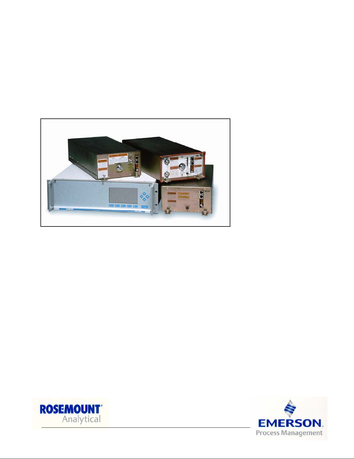
Model NGA2000 FID
Flame Ionization Detector Module
http://www.processanalytic.com
Page 2

ESSENTIAL INSTRUCTIONS
READ THIS PAGE BEFORE PROCEEDING!
Rosemount Analytical designs, manufactures and tests its products to meet many national and international standards. Because these instruments are sophisticated technical products, you
MUST properly install, use, and maintain them
normal specifications. The following instructions MUST be adhered to and integrated into your
safety program when installing, using, and maintaining Rosemount Analytical products. Failure to
follow the proper instructions may cause any one of the following situations to occur: Loss of life;
personal injury; property damage; damage to this instrument; and warranty invalidation.
to ensure they continue to operate within their
• Read all instructions
prior to installing, operating, and servicing the product.
• If you do not understand any of the instructions, contact your Rosemount Analytical representative
for clarification.
• Follow all warnings, cautions, and instructions
marked on and supplied with the product.
• Inform and educate your personnel in the proper installation, operation, and maintenance of
the product.
• Install your equipment as specified in the Installation Instructions of the appropriate Instruc-
tion Manual and per applicable local and national codes. Connect all products to the proper elec-
trical and pressure sources.
• To ensure proper performance, use qualified personnel
to install, operate, update, program, and
maintain the product.
• When replacement parts are required, ensure that qualified people use replacement parts specified by
Rosemount. Unauthorized parts and procedures can affect the product’s performance, place the safe
operation of your process at risk, and VOID YOUR WARRANTY
. Look-alike substitutions may result
in fire, electrical hazards, or improper operation.
• Ensure that all equipment doors are closed and protective covers are in place, except when
maintenance is being performed by qualified persons, to prevent electrical shock and personal
injury.
The information contained in this document is subject to change without notice.
Teflon and Viton are registered trademarks of E.I. duPont de Nemours and Co., Inc.
Kynar® is a registered trademark of Pennwalt, Inc.
Tygon is a registered trademark of Saint-Gobain Performance Plastics
Emerson Process Management
Rosemount Analytical Inc.
Process Analytic Division
1201 N. Main St.
Orrville, OH 44667-0901
T (330) 682-9010
F (330) 684-4434
e-mail: gas.csc@EmersonProcess.com
http://www.processanalytic.com
Page 3

Model NGA2000 FID
TABLE OF CONTENTS
Instruction Manual
760001-A
October 2002
PREFACE...........................................................................................................................................P-1
Definitions ...........................................................................................................................................P-1
Safety Summary .................................................................................................................................P-2
General Precautions For Handling And Storing High Pressure Gas Cylinders .................................P-5
Documentation....................................................................................................................................P-6
Compliances .......................................................................................................................................P-6
Glossary of Terms ............................................................................................................................P-7
1-0 DESCRIPTION AND SPECIFICATIONS..............................................................................1-1
1-1 Overview................................................................................................................................1-1
1-2 Typical Applications...............................................................................................................1-1
1-3 Theory of Technology............................................................................................................1-1
1-4 Gas Safety Features..............................................................................................................1-3
1-5 Fuel Gas Option ....................................................................................................................1-3
1-6 Specifications.........................................................................................................................1-5
a. General ...........................................................................................................................1-5
b. Gas Requirements ..........................................................................................................1-6
c. Physical...........................................................................................................................1-7
d. Gas Connections.............................................................................................................1-7
2-0 INSTALLATION ....................................................................................................................2-1
2-1 Unpacking..............................................................................................................................2-1
2-2 Assembly ...............................................................................................................................2-1
2-3 Location .................................................................................................................................2-2
2-4 Gases ....................................................................................................................................2-3
a. Overview .........................................................................................................................2-3
b. Connections ....................................................................................................................2-3
c. Specifications ..................................................................................................................2-5
d. Leak Test ........................................................................................................................2-6
2-5 Electrical Connections ...........................................................................................................2-6
3-0 OPERATION .........................................................................................................................3-1
3-1 Overview................................................................................................................................3-1
3-2 Displays .................................................................................................................................3-1
3-3 Run Mode Display .................................................................................................................3-1
3-4 Menu Displays .......................................................................................................................3-1
3-5 Help Displays.........................................................................................................................3-1
3-6 Startup Procedure .................................................................................................................3-7
3-7 Binding...................................................................................................................................3-9
3-8 Calibration..............................................................................................................................3-9
3-9 Routine Operation .................................................................................................................3-10
3-10 Safety System .......................................................................................................................3-10
4-0 MAINTENANCE AND SERVICE ..........................................................................................4-1
4-1 Burner disassembly and cleaning .........................................................................................4-1
4-2 Component Replacement......................................................................................................4-2
4-3 Burner Startup Troubleshooting ............................................................................................4-2
Rosemount Analytical Inc. A Division of Emerson Process Management Contents i
Page 4

Instruction Manual
760001-A
October 2002
5-0 REPLACEMENT PARTS ......................................................................................................5-1
5-1 Replacement Parts ................................................................................................................5-1
a. Electronics.......................................................................................................................5-1
b. Burner Assembly and Components ................................................................................5-1
c. Electro-Mechanical..........................................................................................................5-1
d. O-Rings and Gaskets......................................................................................................5-1
e. Pneumatics .....................................................................................................................5-1
5-2 Matrix .....................................................................................................................................5-2
6-0 RETURN OF MATERIAL ......................................................................................................6-1
6-1 Return Of Material .................................................................................................................6-1
6-2 Customer Service ..................................................................................................................6-1
6-3 Training..................................................................................................................................6-1
7-0 APPENDIX A – MENU SCREENS .......................................................................................7-1
8-0 INDEX....................................................................................................................................8-1
Model NGA2000 FID
ii Contents Rosemount Analytical Inc. A Division of Emerson Process Management
Page 5

Model NGA2000 FID
LIST OF ILLUSTRATIONS
Figure 1-1. Flame Ionization Detection Technology..........................................................................1-1
Figure 1-2. FID Component Locations – Top View ...........................................................................1-2
Figure 2-1. Analyzer Module Installation into Platform......................................................................2-1
Figure 2-2. Back Panel Connections.................................................................................................2-2
Figure 2-3. FID Module Flow Diagram ..............................................................................................2-4
Figure 2-4. Front Panel Connections, Controls and Indicators .........................................................2-4
Figure 2-5. Outline and Mounting Dimensions..................................................................................2-7
Figure 2-6. FID Wiring Diagram........................................................................................................2-8
Figure 3-1. Run Mode Display...........................................................................................................3-1
Figure 3-2. Main Menu Display..........................................................................................................3-2
Figure 3-3. Basic Controls Menu Display..........................................................................................3-2
Figure 3-4. Expert Controls and Setup Menu Display.......................................................................3-2
Figure 3-5. Technical Configuration Menu Display ...........................................................................3-3
Figure 3-6. Typical Help Screen........................................................................................................3-3
Figure 3-7. Typical Curves of Module Response vs. Pressure Setting on Sample Pressure
Regulator .......................................................................................................................3-5
Figure 3-8. Typical Curves of Module Response vs. Pressure Setting on Fuel Pressure
Regulator .......................................................................................................................3-5
Figure 3-9. Typical Curves of Module Response vs. Pressure Setting on Air Pressure
Regulator .......................................................................................................................3-6
Figure 3-10. Front Panel Torque Sequence........................................................................................3-11
Figure 4-1. FID Burner Assembly – Exploded View..........................................................................4-3
Instruction Manual
760001-A
October 2002
LIST OF TABLES
Table 1-1. Analyzer Characteristics Relative to Fuel Gas ...............................................................1-4
Table 3-1. FID Analyzer Module Alarms ..........................................................................................3-4
Rosemount Analytical Inc. A Division of Emerson Process Management Contents iii
Page 6

Instruction Manual
760001-A
October 2002
Model NGA2000 FID
iv Contents Rosemount Analytical Inc. A Division of Emerson Process Management
Page 7
Model NGA2000 FID
The purpose of this manual is to provide information concerning the components,
functions, installation and maintenance of the NGA2000 FID and the System Accessories
of the NGA2000 System.
Some sections may describe equipment not used in your configuration. The user should
become thoroughly familiar with the operation of this module before operating it. Read
this instruction manual completely.
The following definitions apply to DANGERS, WARNINGS, CAUTIONS and NOTES found throughout
this publication.
Instruction Manual
760001-A
October 2002
PREFACE
DEFINITIONS
DANGER .
Highlights the presence of a hazard which will cause severe personal injury, death, or substantial
property damage if the warning is ignored.
WARNING .
Highlights an operation or maintenance procedure, practice, condition, statement, etc. If not
strictly observed, could result in injury, death, or long-term health hazards of personnel.
CAUTION.
Highlights an operation or maintenance procedure, practice, condition, statement, etc. If not
strictly observed, could result in damage to or destruction of equipment, or loss of effectiveness.
NOTE
Highlights an essential operating procedure,
condition or statement.
Rosemount Analytical Inc. A Division of Emerson Process Management Preface P-1
Page 8
Instruction Manual
760001-A
October 2002
Model NGA2000 FID
SAFETY SUMMARY
If this equipment is used in a manner not specified in these instructions, protective systems may be impaired.
AUTHORIZED PERSONNEL
To avoid explosion, loss of life, personal injury and damage to this equipment and on-site property,
all personnel authorized to install, operate and service the this equipment should be thoroughly
familiar with and strictly follow the instructions in this manual. SAVE THESE INSTRUCTIONS.
DANGER.
ELECTRICAL SHOCK HAZARD
Do not operate without doors and covers secure. Servicing requires access to live parts which can
cause death or serious injury. Refer servicing to qualified personnel. For safety and proper performance this instrument must be connected to a properly grounded three-wire source of power.
WARNING .
POSSIBLE EXPLOSION HAZARD
This equipment is used in the analysis of sample gases which may be flammable, and the burner
fuel used in the ionization process is flammable. A continuous dilution purge system is factory-installed (in accordance with Standard ANSI/NFPA 496-1993, Chapter 6, and it must be functional at all times during operation. Do not disable this purge system.
WARNING .
FLAMMABLE SAMPLES
Consult the factory if flammable samples will be measured.
WARNING.
PARTS INTEGRITY
Tampering or unauthorized substitution of components may adversely affect safety of this product.
Use only factory documented components for repair.
P-2 Preface Rosemount Analytical Inc. A Division of Emerson Process Management
Page 9

Model NGA2000 FID
Do not place hands or fingers in the Platform front handles when front panel is open. Dropping the
front panel of the Platform while hand or fingers are inside either handle can cause serious injury.
Ensure that all gas connections are made as labeled and are leak free. Improper gas connections
could result in explosion or death.
This module requires periodic use of pressurized gas. See General Precautions for Handling and
Storing High Pressure Gas Cylinders, page P-5.
Instruction Manual
760001-A
October 2002
WARNING.
HAND INJURY HAZARD
WARNING.
POSSIBLE EXPLOSION HAZARD
CAUTION .
PRESSURIZED GAS
CAUTION .
PURGE AIR REQUIREMENT
This Analyzer Module must be used in conjunction with a device (Control Module or PC Interface)
that can actively monitor network variables related to pressure or flow of the continuous dilution
purge, or the front panel LEDs of the Analyzer Module, as installed, must be visible. The purpose of
this requirement is to maintain adherence to ANSI/NFPA 496 standard which assures the continued
viability of the purge system. Under no circumstances should any pressure or flow indicator be
connected to the PURGE AIR OUT outlet of the Analyzer Module because this may affect the sealing
performance of the module.
CAUTION.
OVER-VOLTAGE SPIKING
If this Analyzer Module is used with a non-Rosemount Analytical power supply, adding Rosemount
P/N 903341 Current Protector in series with the 24 V positive power line will prevent over-voltage
spiking and resultant fuse blowing when powering up the instrument.
Rosemount Analytical Inc. A Division of Emerson Process Management Preface P-3
Page 10

Instruction Manual
760001-A
October 2002
Model NGA2000 FID
CAUTION .
STATIC ELECTRICITY
Circuit boards in this instrument are static-sensitive. Take all static precautions when handling the
circuit boards
NOTE
This Analyzer Module is completely leak-tested at the factory for gas leakage. The user is responsible for testing for leakage at the inlet and outlet fittings on the rear panel (with a test procedure
chosen by the user). The user is also responsible for leak-testing periodically and if any internal
pneumatic components are adjusted or replaced. See leak test instructions in Section2-4d on page
2-6.
P-4 Preface Rosemount Analytical Inc. A Division of Emerson Process Management
Page 11

Instruction Manual
760001-A
Model NGA2000 FID
October 2002
GENERAL PRECAUTIONS FOR HANDLING AND STORING HIGH
PRESSURE GAS CYLINDERS
Edited from selected paragraphs of the Compressed Gas Association's "Handbook of Compressed
Gases" published in 1981
Compressed Gas Association
1235 Jefferson Davis Highway
Arlington, Virginia 22202
Used by Permission
1. Never drop cylinders or permit them to strike each other violently.
2. Cylinders may be stored in the open, but in such cases, should be protected against extremes of
weather and, to prevent rusting, from the dampness of the ground. Cylinders should be stored in the
shade when located in areas where extreme temperatures are prevalent.
3. The valve protection cap should be left on each cylinder until it has been secured against a wall or
bench, or placed in a cylinder stand, and is ready to be used.
4. Avoid dragging, rolling, or sliding cylinders, even for a short distance; they should be moved by using a
suitable hand-truck.
5. Never tamper with safety devices in valves or cylinders.
6. Do not store full and empty cylinders together. Serious suckback can occur when an empty cylinder is
attached to a pressurized system.
7. No part of cylinder should be subjected to a temperature higher than 125
never be permitted to come in contact with any part of a compressed gas cylinder.
8. Do not place cylinders where they may become part of an electric circuit. When electric arc welding,
precautions must be taken to prevent striking an arc against the cylinder.
°
F (52°C). A flame should
Rosemount Analytical Inc. A Division of Emerson Process Management Preface P-5
Page 12
Instruction Manual
9
6
760001-A
October 2002
Model NGA2000 FID
DOCUMENTATION
The following NGA2000 FID instruction materials are available. Contact Customer Service Center or the
local representative to order.
760001 Instruction Manual (this document)
COMPLIANCES
This product may carry approvals from several certifying agencies, including Factory Mutual and the Canadian Standards Association (which is also an OSHA accredited Nationally Recognized Testing Laboratory,
NRTL) for use in non-hazardous, indoor locations.
The certification marks appear on the product name-rating plate.
Rosemount Analytical Inc. has satisfied all obligations from the European Legislation to harmonize the
product requirements in Europe.
This product complies with the standard level of NAMUR EMC. Recommendation (May 1993).
This product satisfies all obligations of all relevant standards of the EMC framework in Australia and New
Zealand.
FM
APPROVED
®
97-C219
NAMUR
N
P-6 Preface Rosemount Analytical Inc. A Division of Emerson Process Management
Page 13

Model NGA2000 FID
GLOSSARY OF TERMS
Analyzer Module
The module that contains all sensor/detector components for development of a Primary Variable signal; includes all signal conditioning and temperature control circuitry.
Backplane
The interconnect circuit board which the Controller Board, Power Supply, Analyzer Module power and network cables, I/O Modules and Expansion Modules plug into.
Control Module
The Operator Interface plus the Controller Board.
Controller Board
The computer board that serves as the Network Manager and operates the Display and Keypad.
Instruction Manual
760001-A
October 2002
Distribution Assembly
The Backplane and the card cages that hold I/O and Expansion Modules.
Expansion Module
A circuit board that plugs into the Backplane from the front of the Platform and performs special features
not related to I/O functions.
I/O Module
A circuit board that plugs into the Backplane from the rear of the Platform. Has a connector terminal for
communication with external data acquisition devices and provides an input/output function.
Operator Interface
The Display and Keyboard.
Platform
Any workable collection of the following: Controller Board, Power Supply, Distribution Assembly, Enclosure
and Operator Interface.
Power Supply
Any of a variety of components that provides conditioned power to other NGA2000 components, from the
Power Supply Board that plugs into the front of the Backplane in a stand-alone instrument to several larger
ones that can power larger collections of modules and components.
Primary Variable
The measured species concentration value from an Analyzer Module.
Secondary Variable
Data placed on the network by a module regarding current status, e.g., sample flow, source voltage and
other diagnostic information.
Rosemount Analytical Inc. A Division of Emerson Process Management Preface P-7
Page 14

Instruction Manual
760001-A
October 2002
Model NGA2000 FID
Softkeys
The five function keys located below the front panel display; they assume the function displayed directly
above each on the display, a function dictated by software.
System
Any collection of Analyzer Module(s), Platform(s), I/O Module(s) and Expansion Module(s).
P-8 Preface Rosemount Analytical Inc. A Division of Emerson Process Management
Page 15

Model NGA2000 FID
A
DESCRIPTION AND SPECIFICATIONS
1-1 OVERVIEW
Instruction Manual
760001-A
October 2002
SECTION 1
This manual describes the Flame Ionization
Detector (FID) Analyzer Module of Rosemount Analytical's NGA2000 Series of gas
analysis components. See Figure 1-1 below
and Figure 1-2 on page 1-2.
The FID Analyzer Module is designed to continuously determine the concentration of hydrocarbons in a flowing gaseous mixture. The
concentration is expressed in parts-per-million
or percent of volume.
The entire FID Analyzer Module is designed
as a slide-in module (if configured in
stand-alone instrument fashion), removable
from the front of the Platform, with gas connections made from the rear. All electronics
relative to sample detection and conditioning
are included in this module.
1-2 TYPICAL APPLICATIONS
The monitoring of atmospheric air for low-level
hydrocarbon contaminants and determining
the hydrocarbon content of exhaust emissions
from internal combustion engines are examples of typical applications for the FID Analyzer Module.
1-3 THEORY OF TECHNOLOGY
This Analyzer Module uses the flame ionization method of detection. The sensor is a
burner in which a regulated flow of sample
gas passes through a flame sustained by
regulated flows of a fuel gas (hydrogen or a
hydrogen/diluent mixture) and air.
Within the flame, the hydrocarbon components of the sample stream undergo a complex ionization that produces electrons and
positive ions. Polarized electrodes collect
these ions, causing current to flow through an
electronic measuring circuit
The ionization current is proportional to the
rate at which carbon atoms enter the burner,
and is therefore a measure of the concentration of hydrocarbons in the sample. This
measure of concentration is placed on the
network, where it is can be shown on the Platform Display or on other data acquisition devices.
Negative Ion
Collection
Ring
+90V
Sample
Figure 1-1. Flame Ionization Detection
Technology
Signal
Conditioning
Positive
Carbon
Ions
ir
Fuel
Rosemount Analytical Inc. A Division of Emerson Process Management Description and Specifications 1-1
Page 16
Instruction Manual
A
760001-A
October 2002
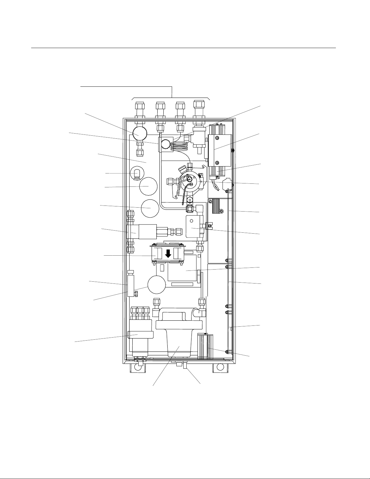
Gas Lines
(See Figure 2-2)
Fuel Shutoff
Solenoid Valve
Capillary
Case Heater Silicon
Pad (On Base)
Purge Air Flow Switch
Fuel Pressure Sensor
Air Pressure Sensor
Ignite/Operate Mode
Burner-Air Flow
Solenoid Valve
ir Circulation Fan
Purge Air
Heater Cartridge
Sample Pressure
Sensor
Burner Air
and Fuel
Regulators
(Stacked Vertically)
Sample Back Pressure Regulators
Model NGA2000 FID
Purge Air
Pressure Regulator
Purge Air Outlet
Pressure Switch
Preamp Board
(In Shield)
Detector (Burner)
Computer Board
Sample Bypass
Flow Sensor
DC-DC Converter
Safety Board
Power Supply Board
Network & Power Module
Manual Ignite Switch
Figure 1-2. FID Component Locations – Top View
1-2 Description and Specifications Rosemount Analytical Inc. A Division of Emerson Process Management
Page 17

Model NGA2000 FID
1-4 GAS SAFETY FEATURES
The FID Analyzer Module is designed with a
factory installed continuous dilution purge system in accordance with standard ANSI/NFPA
496 - 1993, Chapter 6. Front-panel LEDs indicate that the burner flame is lit and that the
purge system is enabled. In addition, fuel gas
is automatically shut off when a flame-out
condition occurs or the safety system is disabled.
The purge system is enabled only if there is
proper purge gas flow in, purge gas pressure,
and internal case pressure, and after five
times the case volume has been exchanged.
All tubing ahead of the burner is rigid metallic
tubing assembled with ferrule/nut type compression fittings. However, should an internal
fuel leak occur, a worst-case leak would be
dissipated below 25% of the LEL of hydrogen
through the combination of an inlet fuel flow
restrictor and purge gas flow.
This module is designed to use 100% hydrogen fuel or 40% H
mum inlet pressure of 3446 hPa-gauge (50
psig). A different flow restrictor is used for
each fuel type.
A standard FID Analyzer Module is only
equipped to analyze a non-flammable sample,
below 100% of the LEL.
POSSIBLE EXPLOSION HAZARD
Protection against explosion depends
upon a special fuel flow restrictor in the
fuel inlet fitting. Do not remove fuel inlet
restrictor. Use the correct fuel flow restrictor for the fuel being used. Do not use
100% hydrogen fuel in a 40% H2/60% He
configured Analyzer Module. Replace only
with factory supplied fitting.
2/60% He fuel at a maxi-
WARNING
Instruction Manual
760001-A
October 2002
equipped to use 100% hydrogen fuel. The
particular application and characteristics of
the sample gas to be measured will dictate
the preferred type of fuel. The following guidelines can be used for determining fuel gas
type:
1. For measuring low-level hydrocarbons in
ambient air or in other sample gas with
relatively constant oxygen content, 100%
hydrogen is preferable. It provides the
highest obtainable sensitivity and maximum stability. Zero drift caused by ambient temperature variations of the fuel
cylinder is somewhat lower for 100%
hydrogen than for mixed fuel. (With either
fuel, it is desirable to maintain a constant
cylinder temperature.)
2. For monitoring internal combustion exhaust emissions or other sample gas with
varying oxygen content, mixed fuel is
preferable. In fact, a hydrogen/helium
mixture is more desirable than a hydrogen/nitrogen mixture. With this type of
sample, the use of mixed fuel gas minimizes the error introduced by oxygen
synergism.
An effective way to reduce the effect of internal oxygen is to dilute it with an inert gas. This
can be accomplished with a constant dilution
of sample and calibration gases upstream
from the burner. But it is simpler and more accurate to provide that diluent in the form of
premixed fuel. Both nitrogen and helium have
been used as a diluent, but helium has proven
to be most effective in improving the quality of
response to the various species of hydrocarbons.
As indicated earlier the flame output signal is
optimum when the ratio of hydrogen flow to
inert flow is about 40/60. Therefore, this is the
chosen composition for hydrogen/helium premixed fuel.
The sample flow is kept low to maximize the
1-5 FUEL GAS OPTION
The standard FID Analyzer Module requires
40% hydrogen/60% helium burner fuel gas.
As an option, the analyzer module can be
Rosemount Analytical Inc. A Division of Emerson Process Management Description and Specifications 1-3
dilution effect while still providing adequate
sensitivity. The burner air flow is normally
about four times the fuel flow, and changes
have little effect on signal strength. For a
Page 18

Instruction Manual
760001-A
October 2002
given flow, the signal can be optimized by adjusting the fuel flow rate.
Typical flow rates with premixed fuel:
Model NGA2000 FID
with the latter. However, in any application
where the sample contains more than one
species of hydrogen and/or a varying concentration of oxygen, mixed fuel is preferred.
Fuel 100 cc/min
Sample 7 cc/min
Air 400 cc/min
Note that with a 40/60 premixed fuel, the
above flow rates amount to 40 cc (8%) hydrogen, 67 cc (13%) inert plus sample and 400
cc (79%) air, which compare closely to the 30
cc (8%) hydrogen, 45 cc (12%) inert/sample
and 300 cc (80%) air noted earlier for straight
hydrogen fuel.
Since sample flow in the case of mixed fuel
operation is only about 1/6 of that with straight
hydrogen fuel, higher sensitivity is obtained
ANALYZER FUEL GAS
CHARACTERISTICS 100% H2 40% H2/60% He
Fullscale Sensitivity 1 ppm, CH4 to 2%, CH4 4 ppm, CH4 to <5%, CH4
Fuel Consumption 35 to 40 cc/min 75 to 80 cc/min
Operating Range 276 to 345 hPa-gauge (4 to 5 psig) 207 to 345 hPa-gauge (3 to 5 psig)
Table 1-1. Analyzer Characteristics Relative to Fuel Gas
The mixed fuel is recommended, not only for
sample containing variable concentrations of
oxygen, but also for a specific pure gas application. If straight oxygen samples are used
with straight hydrogen fuel, the mixture entering the burner is essentially 40% H
which tends to produce an unstable signal.
The mixed fuel works better. Note that the
choice of fuel determines certain analyzer
characteristics, as shown in Table 1-1 below.
2/60% O2,
1-4 Description and Specifications Rosemount Analytical Inc. A Division of Emerson Process Management
Page 19

Model NGA2000 FID
1-6 SPECIFICATIONS
a. General
Measurement Species................... Total hydrocarbons
Ranges .......................................... 0 to 100 ppm (output scalable down to 0-2 ppm
H2/He fuel.............................. low range: 0 to 4 ppm CH
H2 fuel
Repeatability.................................. ≤1% of fullscale at a constant temperature, sample
Minimum Detectable Level
H2/He fuel.............................. 0.04 ppm
H2 fuel
Noise ............................................. ≤1% of fullscale, peak to peak
Linearity ......................................... ≤ ±1% of fullscale for H
Response Time
CEMS .................................... ≤30 sec. For 10% to 90% of fullscale, with sample
ICEE ...................................... ≤1 sec. For 10% to 90% of fullscale, with sample
Zero Drift........................................ ≤ ±1% of fullscale/24 hours at constant
Span Drift....................................... ≤ ±1% of fullscale/24 hours at constant
Effect of Temperature.................... ≤ ±2% of fullscale for any temperature change of
Operating Temperature ................. 32°F to 113°F (0°C to 45°C)
Power Requirements..................... +24 VDC ±5%, 120 W max.. direct to analyzer
1
.................................. low range: 0 to 1 ppm CH4, through 0 to 2500 ppm
1
................................. 0.01 ppm H2 fuel
Instruction Manual
fullscale)
4, through 0 to 1% CH4
high range: 0 to 50 ppm CH4, through 0 to <5%
CH
4
CH4
high range: 0 to 10 ppm CH
CH4
flow and fuel, burner air and sample pressure
bypass flow at 0.5 L/min. (non-flammable sample)
bypass flow at 0.5 L/min. (non-flammable sample)
temperature, hydrocarbon concentration of supply
gases, sample flow and fuel, burner air and sample
pressure
temperature, hydrocarbon concentration of supply
gases, sample flow and fuel, burner air and sample
pressure
10°C and rate of change less than 10°C/hour
module;
Ripple and Noise: <100 mV peak to peak
Line and Load Regulations: <±1%
4, through 0 to 2%
2/He fuel and He fuel
760001-A
October 2002
1
Option
Rosemount Analytical Inc. A Division of Emerson Process Management Description and Specifications 1-5
Page 20

Instruction Manual
760001-A
October 2002
b. Gas Requirements
Sample .......................................... Non-flammable, below 100% of LEL
Flow rate ................................ 0.5 to 40 ml/min.
THC ....................................... ≤0.5 ppm, CH
Supply pressure..................... 483 to 1035 hPa-gauge (7 to 15 psig)
Temperature .......................... 32°F to 132°F (0°C to 55°C), <20°C variance/24
Particulates............................ Filtered to <2 microns
Dewpoint................................ <45°C
Purge Air........................................ Instrument air, nitrogen or other non-flammable
Flow rate: .............................. 16 to 18 L/min.
Supply pressure:.................... 689 to 1378 hPa-gauge (10 to 20 psig)
Fuel Gas (Standard)...................... Premixed 40% hydrogen and 60% helium
Flow rate ................................ 75 to 80 ml/min.
THC ....................................... ≤0.5 ppm, CH
Supply pressure..................... 2415 to 3450 hPa-gauge (35 to 50 psig)
Model NGA2000 FID
4
hours, <10°C variance/hour
gas (refer to ANSI/NFPA 496 for the requirements
for the Protective Gas System)
4
WARNING
POSSIBLE EXPLOSION HAZARD
Unless this Analyzer Module is factory- or field-configured specifically for using
100% hydrogen fuel, DO NOT USE PURE HYDROGEN FUEL. An explosion resulting
in severe personal injury or death could occur. Also, each Analyzer Module is factory-configured for either mixed or pure hydrogen fuel, and cannot use the fuel for
which it was not configured unless field reconfiguration is done.
Fuel Gas (H2 option) ..................... Zero-grade hydrogen
Flow rate ................................ 35 to 40 ml/min.
THC ....................................... ≤0.5 ppm, CH
Supply pressure..................... 2415 to 3450 hPa-gauge (35 to 50 psig)
Burner Air ...................................... Zero-grade air
Flow rate ................................ 350 to 400 ml/min
THC ....................................... ≤ ppm, CH
Supply pressure............................. 1725 to 3450 hPa-gauge (25 to 50 psig)
4
4
1-6 Description and Specifications Rosemount Analytical Inc. A Division of Emerson Process Management
Page 21

Model NGA2000 FID
c. Physical
Case Classification:....................... General purpose for installation in
Maximum Separation .................... 1600m (1 mile) from Analyzer Module to Platform
Materials in Contact With Sample . Stainless steel, Teflon, glass-filled Teflon, brass,
Dimensions.................................... See Outline and Mounting Dimensions, Figure 2-5
Weight ........................................... 10.43 kg (23 lbs.)
Mounting........................................ Horizontal, inside a Platform or custom installed in
d. Gas Connections
Sample In: ..................................... 1/4" O.D. tube fitting, stainless steel
Regulated Air In: ..............................1/4" O.D. tube fitting, brass
Burner Air In: ....................................1/4" O.D. tube fitting, brass
Fuel In:..............................................1/4" O.D. tube fitting, stainless steel
Purge Air In: .....................................3/8" O.D. tube fitting, brass
Purge Air Out: ..................................3/8" O.D. tube fitting, brass
Bypass Out:......................................1/4" O.D. tube fitting, stainless steel
Burner Exhaust Out: ........................1/2 inch O.D. tube connection, Tygon or equivalent
Pressure Relief Valve
Instruction Manual
760001-A
October 2002
weather-protected area
neoprene, Kynar
on page 2-7
a panel
(this connection shall slope downward 6° minimum
from horizontal)
CAUTION
PRESSURE RELIEF VALVE RESTRICTION
No connection shall be made to this fitting. If this caution is ignored, damage to the
case seals may occur, and the instrument will not operate properly.
See the Preface section of the Platform Components manual for specifications regarding Platform-related components and the Preface of the I/O Module manual for
specifications regarding I/O (e.g., relay outputs).
Rosemount Analytical Inc. A Division of Emerson Process Management Description and Specifications 1-7
Page 22

Instruction Manual
760001-A
October 2002
Model NGA2000 FID
1-8 Description and Specifications Rosemount Analytical Inc. A Division of Emerson Process Management
Page 23
Model NGA2000 FID
A
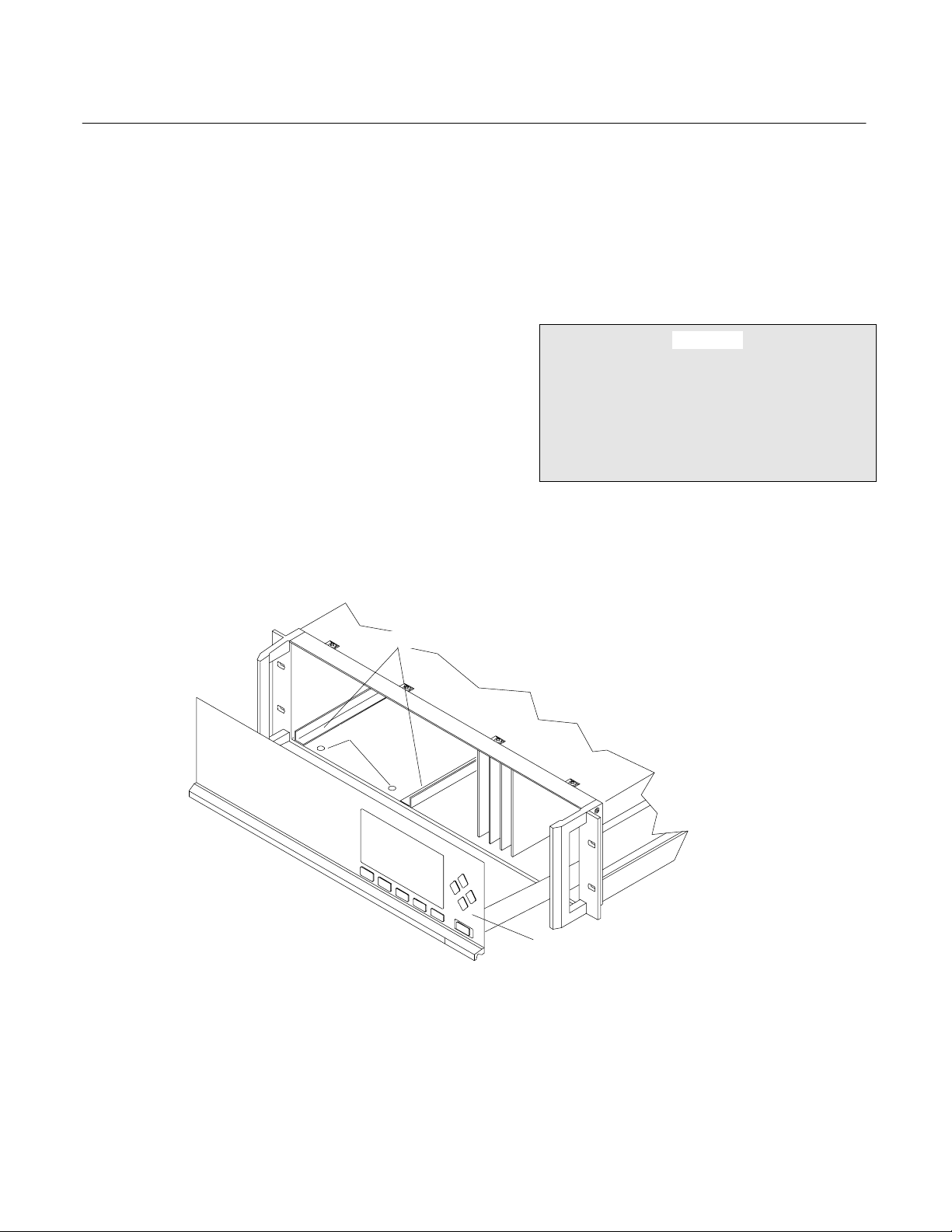
2-1 UNPACKING
If the FID Analyzer Module is received as a
separate unit, carefully examine the shipping
carton and contents for signs of damage.
Immediately notify the shipping carrier if the
carton or contents is damaged. Retain the
carton and packing material until all
components associated with the Analyzer
Module are operational.
2-2 ASSEMBLY
If the Analyzer Module requires assembly with
other components (e.g., the Platform and
associated I/O Modules), do so at this time.
PIN SEATS
Instruction Manual
760001-A
October 2002
SECTION 2
INSTALLATION
Following the guides on the bottom left and
bottom center of the Platform, carefully slide
the Analyzer Module halfway into place.
CAUTION
HAND INJURY HAZARD
Do not place hands or fingers in Platform
front handles when the front panel is open.
Dropping front panel while hand or fingers
are inside either handle can cause serious
injury.
NALYZER MODULE GUIDES
DISENGAGED FRONT PANEL
Figure 2-1. Analyzer Module Installation Into Platform
Rosemount Analytical Inc. A Division of Emerson Process Management Installation
2-1
Page 24
Instruction Manual
760001-A
October 2002INSTALLATION
Lift the spring loaded pins on the front of the
module, and carefully slide it the rest of the
distance. Secure the module in position by
releasing the pins, which seat in the available
holes in the bottom of the case (see Figure
2-1 on page 2-1). If the module and Platform
are difficult to assemble, remove the module,
ensure the top cover of the module is firmly
seated on the hold down screws, and repeat
the assembly procedure.
Connect the network cable to either the
NETWORK 1 or NETWORK 2 connection on
the Analyzer Module (see Figure 2-4 on page
2-4), and the NETWORK connection on the
Backplane (see Platform manual). Connect
the power cable to both the Analyzer Module
front panel and to the Backplane.
Install I/O Module(s) according to guidelines in
the I/O manual. After startup and calibration
have been performed, secure the Front Panel
with the six screws provided.
Model NGA2000 FID
WARNING
INSTALLATION RESTRICTIONS
For safety, the Analyzer Module should be
installed in a non-confined, ventilated
space. Do not block any of the rear panel
outlets as they are part of the safety
system.
Operating ambient temperature is 0°C to
45°C, limited to temperature changes of less
than 10°C/hr. Acceptable dewpoint range is
less than 95% relative humidity, but not in
excess of 45°C wet bulb temperature.
The cylinders of fuel, air, and calibration
gas(es) and the source of purge air should be
located in an area of relatively constant
ambient temperature.
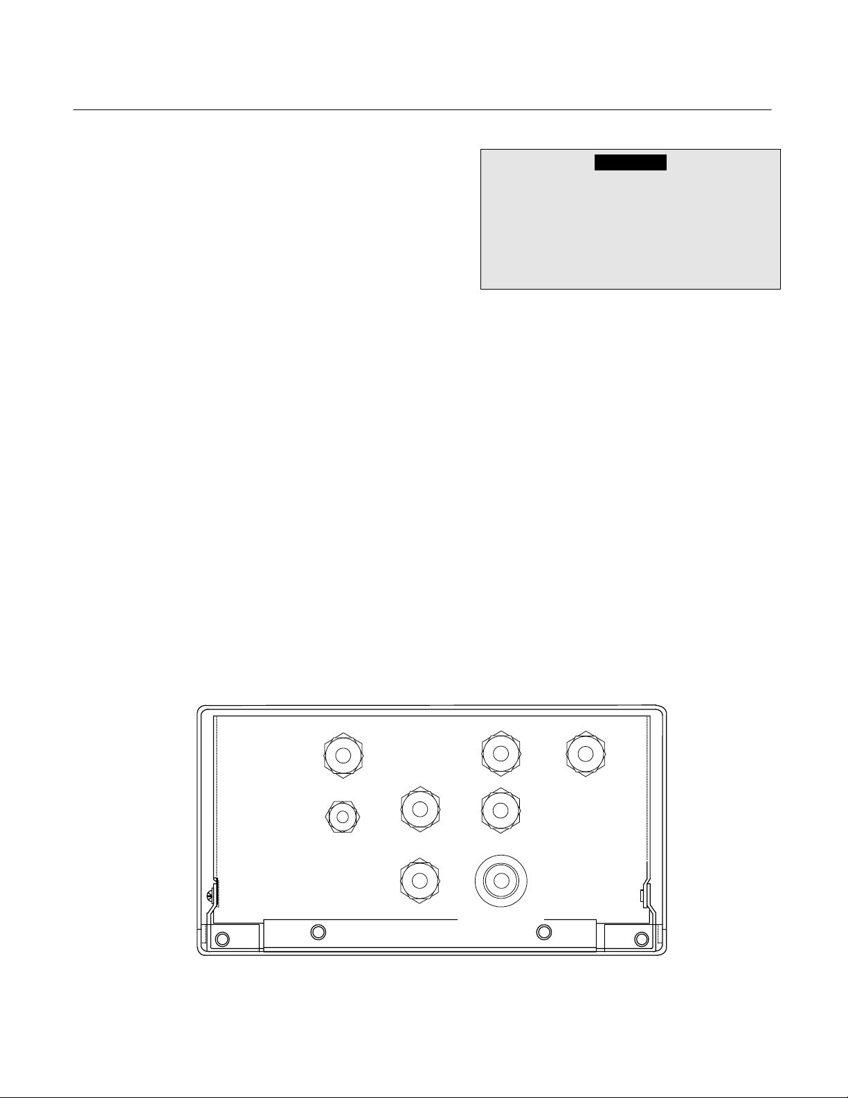
2-3 LOCATION
Install the Analyzer Module in a clean,
weather-proofed, non-hazardous, vibration
free location free from extreme temperature
variations. For best results, install the
Analyzer Module near the sample stream to
minimize sample transport time.
PURGE
AIR OUT
PRESSURE
RELIEF
VALVE
MIXED
FUEL
IN
BURNER
SAMPLE
IN
PURGE
AIR IN
AIR IN
BYPASS
OUT
VENT TO SAFE AREA
SLOPE DOWNWARD
6 MINIMUM
MAXIMUM INPUT PRESSURE
BURNER AIR: 50 PSIG (3450 hPa)
PURGE AIR: 20 PSIG (1378 hPa)
BURNER
EXHAUST
OUT
FUEL: 50 PSIG (3450 hPa)
SAMPLE: 15 PSIG (1035 hPa)
Figure 2-2. Back Panel Connections
Installation Rosemount Analytical Inc. A Division of Emerson Process Management
2-2
Page 25

Model NGA2000 FID
2-4 GASES
a. Overview
During normal operation, the Analyzer
Module requires fuel and air to maintain
the burner flame as well as suitable standard gases for calibration and instrument
air for purge requirements. Criteria for selection of these gases follow in 2-4c on
page 2-5.
After initial startup or after startup following a prolonged shutdown, the analyzer
may display baseline drift for a considerable period of time, particularly on the
most sensitive range. Commonly, the drift
is caused by small amounts of hydrocarbons in the inner walls of the tubing in
both the internal flow system and the external gas supply system. Drift results
from any factor influencing the equilibrium
of these absorbed hydrocarbons, such as
temperature or pressure.
Note that this type of drift occurs only
when the flame is burning. If drift occurs
when the flame is extinguished, the electronic circuitry is at fault. To minimize drift,
use clean fuel and air, keep the analyzer
clean, and locate the gas cylinders in an
area of relatively constant ambient temperature.
The cylinders supplying all gases each
should be equipped with a clean, hydrocarbon free, two stage regulator and a
shutoff valve.
All new external gas tubing (except for
PURGE IN/OUT and SAMPLE BYPASS) is
strongly recommended, preferably precleaned, stain-less steel, gas chromatograph
grade tubing. Thoroughly clean before use. if
a hydrocarbon based cleaning solvent
such as acetone is used, purge tubing
with dry nitrogen or helium for several
minutes before using.
Instruction Manual
760001-A
October 2002
Since the oxidation of hydrogen is accompanied by the formation of water vapor, the Exhaust tubing always should be
slanted downward at least 6 degrees from
horizontal. Otherwise, water may accumulate in the line, causing back pressure and
noisy readings, or may back up in the line
and flood the burner.
If the sample is toxic or noxious, or is to
be reclaimed, connect the Bypass outlet
to a suitable disposal system. Do not use
any device that may cause back pressure
in the line.
Purge air and burner air should be supplied from separate sources.
b. Connections
Reference Figure 2-2 on page 2-2. Connect inlet and outlet lines for sample,
burner fuel and air, exhaust, bypass, and
purge to appropriately labeled fittings on
the rear panel. All connections are 1/4
inch ferrule type compression fittings except the PURGE AIR IN and OUT connections, which are 3/8 inch compression
fittings. The BURNER EXHAUST OUT is
a 1/2 inch connection. Burner exhaust,
bypass and purge air out must be vented
at atmospheric pressure to a nonclassified location in accordance with
ANSI/NFPA-496.
It is recommended that no connection be
made to the PURGE AIR OUT port. If,
however, the analyzer's location requires
interconnection with a venting system, the
3/8" O.D. line should be kept as short as
possible, and no longer than four feet.
CAUTION
POSSIBLE INSTRUMENT DAMAGE
No connection should be made to the
PRESSURE RELIEF VALVE fitting. Doing
so may cause damage to the instrument.
Gas line connections are compression fittings. Do not use pipe thread tape.
Rosemount Analytical Inc. A Division of Emerson Process Management Installation 2-3
Page 26

Instruction Manual
V
760001-A
October 2002
BURNER
EXHAUST
OUT
REGULATOR
Restrictor
PURGE AIR
Plug
1/4MPT
Brass
Run Tee
1/4T - 1/8MPT
Brass
Tubing, Teflon
1/4” OD
PURGE
FLOW
SWITCH
Bulkhead
3/8T
Brass
Tubing, SS
3/8” OD
PURGE AIR
SENSOR
PURGE
AIR
HEATER
Model NGA2000 FID
SAMPLE
IN
IN
CAPILLARY
Tubing, Viton
1/4” OD
PURGE
PRESS
SAMPLE
PRESS
SENSOR
Branch Tee
1/8T - 1/8FPT
SS
SAMPLE
BACK PRESS
REGULATOR
Figure 2-3. FID Module Flow Diagram
BURNER
AIR
!
!
FUEL
Figure 2-4. Front Panel Connections, Controls and Indicators
BYPASS
SAMPLE
Elbow
1/8T - 1/8MPT
Kynar
Connector
1/8T - 1/8MPT
Kynar
WARNING
ATTENTION
OUT
Bulkhead Reducer
1/4T - 1/8T
Brass
Tubing,
Teflon
1/8” OD
FLOW
SENSOR
Tubing,
Teflon
1/8” OD
Elbow
1/8T - 1/4MPT
SS
BURNER
AIR PRESSURE
REGULATOR
SAMPLE
FUEL OVERRIDE
BURNER
AIR IN
Bulkhead Reducer
1/4T - 1/8T
SS
GA
IN OUT
BURNER
AIR
PRESS
SENSOR
POWER
HEAT
FLAME
ON
PURGE
Filter
LON
LON
1 +
AIR
2 -
3 GND
T 6A
260V
COM
3-WAY
VALVE
1
2
IGNITE
Run Tee
1/4T - 1/4FPT
Brass
PURGE AIR
OUT
NC
Run Tee
1/8T - 1/8MPT
SS
FID
WARNING
!
ATTE NTION
!
Bulkhead Connector
1/4T - 1/8NPT
SS
Fuel Restrictor
Purge Exit
Restrictor
PRESS
SW
Connector
1/16T - 1/8MPT
SS
BURNER
MIXED FUEL
IN
SOLENOID
ALVE
Tubing,
Viton
1/4” OD
FUEL
PRESS
SENSOR
Fuel Restrictor
NETWORK 1
NETWORK 2
POWER
FUSE
Connector
1/8T - 1/8MPT
SS
FUEL
PRESSURE
REGULATOR
2-4 Installation Rosemount Analytical Inc. A Division of Emerson Process Management
Page 27

Model NGA2000 FID
c. Specifications
Fuel Gas
Standard analysis usually requires mixed
fuel, i.e., 40% (±2%) hydrogen and 60%
helium. H2/He mixed fuel is recommended over H2/N2 fuel because of better linearity in concentration output. Such
blends are supplied by many gas vendors
specifically for this use, with a guaranteed
maximum total hydrocarbon content of 0.5
ppm, measured as methane. This specification should be used when obtaining
these mixtures.
NOTE
The fuel restrictor is marked with a red
dot, and the sample capillary is marked
with a red or green dot for mixed fuel
applications.
Some applications require the use of
100% hydrogen fuel. When using this
option, always ensure that sample
pressure (4 to 5 psig) is present when
fuel flow is present. Otherwise, the detector tip may be damaged.
The fuel restrictor and sample capillary
are marked with a white dot for 100%
hydrogen fuel applications.
Burner Air
In order to ensure a low background signal, burner air should contain less than 1
ppm maximum total hydrocarbon content.
An alternate source for burner air and
zero gas (see CALIBRATION GASES below) is a combination diaphragm pump
and heated palladium catalyst. This process continuously removes moderate
amounts of hydrocarbons and carbon
monoxide from ambient air.
Purge Air
Instrument quality air, nitrogen, or other
nonflammable gas is required for the
safety purge system.
Instruction Manual
760001-A
October 2002
Calibration Gases
Calibration method and gases depends
on the type of fuel gas used, the operating
range, and the desired measurement accuracy. In all methods, zero and span
gases are used, and are introduced
through the sample inlet at the rear of the
module.
Z
ERO GAS - Analysis is affected by the
background gas of the sample. Therefore,
it is recommended to use zero gas with as
close to the background composition of
the sample as possible. Normally less
than 0.5 THC as CH
If the burner fuel is 100% hydrogen, the
zero gas, background gas of the sample
or background gas of the span gas cannot
be hydrogen or oxygen. These gases
combined with pure hydrogen fuel would
generate excessive heat in the burner,
causing deterioration of the internal components of the burner.
S
PAN GAS - Span gas consists of a speci-
fied concentration of methane or other
hydrocarbon in a background gas such as
nitrogen. Analysis is affected by the
background gas of the sample. Therefore, span gas containing the same
background gas as the sample is recommended. Then, the background effect is canceled out.
S
AMPLE GAS - Sample gas should be non-
flammable (below 100% of the sample's
LEL). For high sensitivity applications requiring background gas compensation,
contact the factory.
F
LOW RATE - The sample flow rate must
be between 0.5 L/min. and 2 L/min. Flow
rate for purge air should be 16 to 18
L/min.
P
RESSURIZATION/FILTRATION - Sample
pressure at the SAMPLE inlet should be
within the range of 483 to 1035
hPa-gauge (7 to 15 psig), and internally,
should be 345 hPa-gauge (5 psig) nominally. Burner fuel pressures should be:
4 is sufficient.
Rosemount Analytical Inc. A Division of Emerson Process Management Installation 2-5
Page 28

Instruction Manual
760001-A
October 2002
1725 to 3450 hPa-gauge (25 to 50 psig)
for cylinder regulator, 1518 to
1723 hPa-gauge (22 to 25 psig) internal.
Burner air pressures should be: 1725 to
3450 hPa-gauge (25 to 50 psig) for cylinder regulator, 965 to 1103 hPa-gauge (14
to 16 psig) internal. Purge air (external
supply) pressure should be between 689
and 1378 hPa-gauge (10 and 20 psig),
689 to 827 hPa-gauge (10 to 12 psig)
nominal. The internal purge air regulator
pressure is factory preset at a nominal
setting of 551 hPa-gauge (8 psig) with a
supply pressure of 689 hPa-gauge (10
psig). Noncompliance with these specifications, particularly those concerning
purge air, could cause over-pressure
damage to the module. The nominal internal case pressure is about 0.5 to 1.0
inch of water, and the pressure relief
valve is set at 1/3 psig (nominal).
At the very least, the module's safety system, which requires a certain volume of
purge air flowing through the case before
allowing burner ignition, will not allow the
instrument to operate.
Model NGA2000 FID
for accuracy. Sample should be filtered
for particulates down to two microns.
d. LEAK TEST
The Analyzer Module is completely tested
at the factory for gas leakage. The user is
responsible for testing for leakage at the
inlet and outlet fittings on the rear panel.
The user is also responsible for internal
leak testing periodically and if any internal
pneumatic components are adjusted or
replaced (with a test procedure chosen by
the user).
2-5 ELECTRICAL CONNECTIONS
Two electrical connections are required on the
Analyzer Module: POWER and NETWORK.
See Figure 2-4 on page 2-4. On the Analyzer
Module, two NETWORK connectors are
available, either of which is appropriate for: 1)
interconnection with the Backplane of the
Platform or 2) "daisy-chaining" with other
NGA2000 components. Connect Analyzer
Module POWER to Backplane POWER or external 24 VDC power source.
All internal pressure settings are preset at
the factory, but the operator should check
2-6 Installation Rosemount Analytical Inc. A Division of Emerson Process Management
Page 29
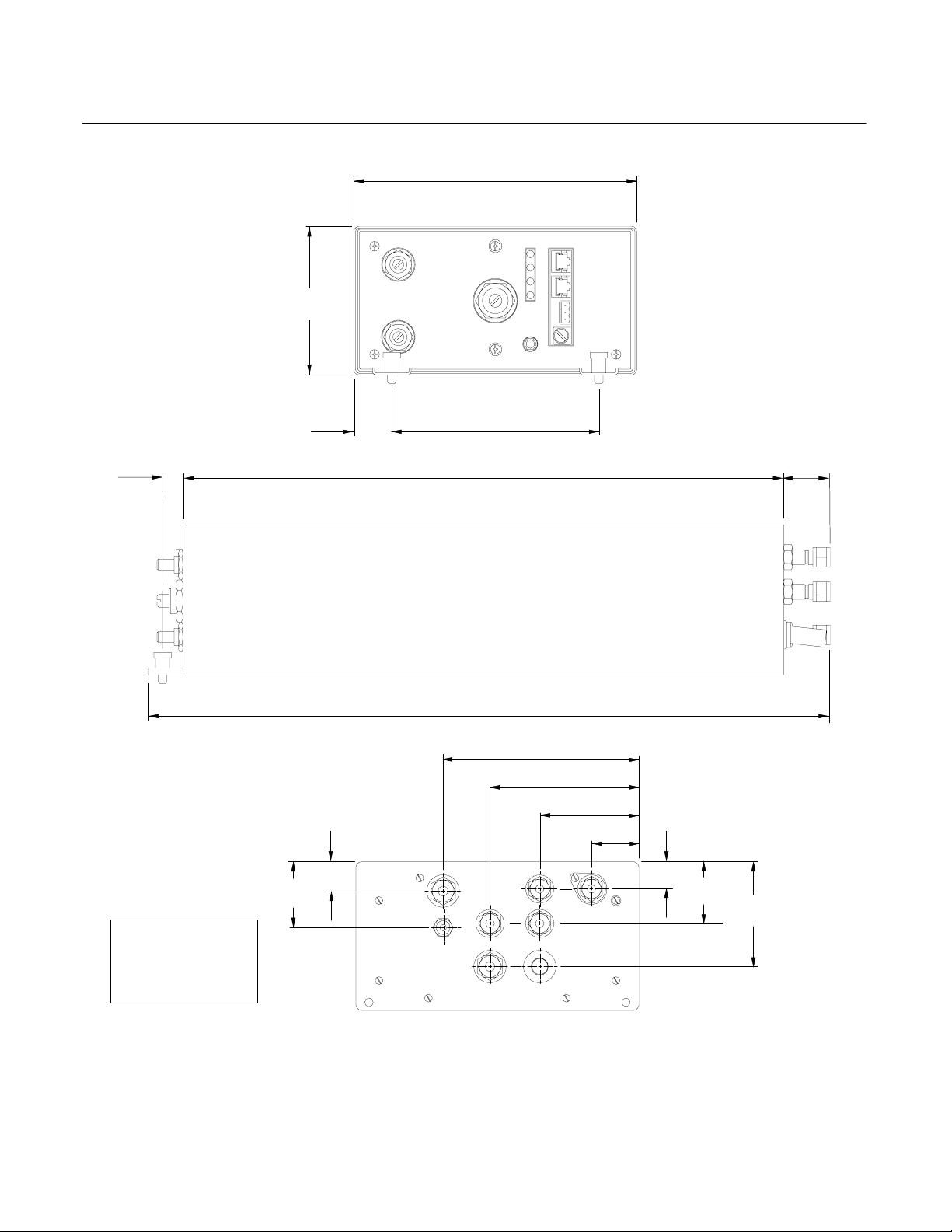
Model NGA2000 FID
.25
[6.3]
Dimensions:
INCHES
[MM]
4.3
[109.7]
1.1
[27.9]
.9
[22.5]
1.9
[49.4]
Figure 2-5. Outline and Mounting Dimensions
[208.2]
[152.4]
17.75
[450.9]
20.0
[510.0]
8.2
6.0
[143.6]
5.7
4.3
[109.1]
FID
2.9
[73.6]
1.4
[35.6]
.8
[20.9]
D
Instruction Manual
760001-A
October 2002
1.7
[43.4]
1.8
[46.3]
3.1
[78.0]
Rosemount Analytical Inc. A Division of Emerson Process Management Installation 2-7
Page 30

Instruction Manual
A
N
R
E
A
A
A
760001-A
October 2002
Model NGA2000 FID
CARTRIDGE
HEATER
CABLE ASSEMBLY,
FLAT 3 COND
LON/POWER
MODULE
J5
P5
E2 24VOLT
GR
RE
BL
N
D
K
E1 RTN
E3
CABLE ASSEMBLY,
FLAT 10 COND
J6
CABLE
ASSEMBLY,
FLAT 24COND
P1
J4
P4
P6
J6
J1
POWER
SUPPLY
BOARD
J5
P5
P9
J9
OVEN HEATER
FUEL SOL.
++ +
J10
P10
YEL
BRN
RED
ORN
GRN
P3
J2
P2
J3
J8
P8
IR
BLU
P15
P11
FAN
J7
P7 J11
BLK
BLK
RED
RED
IR
J15
3-WAY SOLENOID
J14
P14
SENSOR,
CASE TEMP
HARNESS,
CHASSIS
ASSEMBLY
THERMOSTAT
HEATER
CABLE
ASSEMBLY,
COND
FLAT 3
CABLE
ASSEMBLY,
FLAT
16 COND
2-WAY
SOLENOID
J16
P16
FUEL IN
HARNESS, GLOW PLUG
P4
J4
SAFETY
BOARD
J3
P3
SSY,
SWITCH
PRESSURE
SWITCH
CABLE
P2
J2
1 2 3 4 5 6 7 8
FLO
SW
J1
P1
POWER
RESISTOR
FLOW
SENSOR
CASE
PRESS
FLO
SW
FLO
SW
FLO
SEN
HARNESS
J11
J10
J12
CHASSIS
GND
SHIELD
E3
R37
R38
J13
P13
CABLE ASSEMBLY, ANODE
SENSOR, FLAME-OUT
CABLE ASSEMBLY, FLAT
20 COND
MTG
STUD
GND
STRAP
BOARD
J2P2J3
P7
J7
P3
POL
VOL
GRY
CABLE ASSEMBLY,
CATHODE
PUR
P1
J1
E2
EI
SHIELD
PREAMP
BOARD
P6
J6
COMPUTER
ANALYSIS
J5
P5
J4
P4
J1
P1
Figure 2-6. FID Wiring Diagram
2-8 Installation Rosemount Analytical Inc. A Division of Emerson Process Management
POWER
J1
P1
JP1
RTN
J3
P3
SENSOR
AIR
P11
PRESS
SENSOR
FUEL
P10
PRESS
SENSOR
SAMPLE
P12
PRESS
BURNERGND
GLOW
PLUG
ASSEMBLY
J1
P1
OVEN
HEAT
FLAME O
P2
J2
POWER MODULE
ASSEMBLY
J2
J4
CATHODE
BURNER
ASSEMBLY
PURGE AI
SWITCH ASSEM
MANUAL IGNIT
LED INDICATOR
ASSEMBLY
PWR
MOD
J1
J6
J1
J5 +10V REF
NODE
Page 31

Model NGA2000 FID
Secondary Variab
Secondary Variable
Instruction Manual
760001-A
October 2002
SECTION 3
OPERATION
3-1 OVERVIEW
Prior to initial startup, the user should leak test
the module as outlined in Section 2.
For the remainder of this section, Analyzer
Module interconnection with a Platform or
some interfacing component will be assumed.
Display and Keypad information shall refer to
that which the user can expect to see and do
with regard to the Front Panel of the Platform.
(For a complete description of Platform Front
Panel controls and indicators, see Section 1
of the Platform instruction manual.)
3-2 DISPLAYS
Three kinds of Display screens are available
to the user:
• Run Mode
• Menu
• Help
3-3 RUN MODE DISPLAY
The Run Mode is the normal mode of operation. In this mode, the display (see Figure 3-1
below) will show current gas measurement,
the component of interest, user-selectable (up
to four) secondary variables, the current operations of the softkeys, and a graphic bar
representing the displayed concentration as a
percent of fullscale.
If more than one Analyzer Module is connected to the system, another Run Mode display will show up to four gas measurements at
once. Alarm messages may also appear on
the display (See Table 3-1 on page 3-4).
Rosemount Analytical Inc. A Division of Emerson Process Management Operation 3-1
3-4 MENU DISPLAYS
The Main Menu structure enables the user to
access data and functions, and put information onto the network.
The Main Menu (see Figure 3-2 on page 3-2)
is subdivided into three levels of control based
generally on which personnel is likely to use it:
Basic Controls, Expert Controls, and Technical Controls. (See Figure 3-3through Figure
3-5.) Many layers of the menu structure are
described at appropriate places throughout
this manual.
From the Run Mode display, press the
MENUS softkey to gain access to the Main
Menu. (See Figure 3-2 on page 3-2.)
3-5 HELP DISPLAYS
The Help structure is intended to be an on-line
"tutorial," context-sensitive and
topic-interconnected, so that the user can
practically operate NGA2000 without need of
an instruction manual. (See Figure 3-6 on
page 3-3.)
23.2 ppm HC
0 ppm 50
Display Parms. Menu Dual Info
F1
Figure 3-1. Run Mode Display
le: XXX
: XXXX
F2 F3 F4 F5
Analyzer PQ 322-14
Page 32

Instruction Manual
p
p
(
)
(
)
760001-A
October 2002
Model NGA2000 FID
23.2 ppm HC Analyzer XXXXXXXX
Main Menu
Basic Controls
Expert controls and setup ...
Operational configuration
Technical level configuration ...
Diagnostic and manufacturing/service
Delete alarm message!
Display Parms. Info
F1
F2 F3 F4 F5
Figure 3-2. Main Menu Display
23.2 ppm HC Analyzer XXXXXXXX
Basic Controls
Measurement range numbers:
Range upper limit: 10 ppm
Range and functional control: Local
Bypass sample flow: 1000 ml/min
Ranges with valid calibration 1&2
Calibration status: Ready
If it won’t calibrate…
Flame condition: On
Light flame…
Home Escape Zero Span Info
F1
F2 F3 F4 F5
Figure 3-3. Basic Controls Menu Display
23.2 ppm HC Analyzer XXXXXXXX
Ex
ert controls and set u
Expert analyzer controls ...
Auxiliary module controls ...
System set up ...
Analyzer module set up ...
Auxiliary module set up ...
Local I/O set up ...
Home Escape Info
F1
F2 F3 F4 F5
Figure 3-4. Expert Controls and Setup Menu Display
3-2 Operation Rosemount Analytical Inc. A Division of Emerson Process Management
Page 33

Instruction Manual
g
760001-A
Model NGA2000 FID
Rosemount Analytical Inc. A Division of Emerson Process Management Operation 3-3
23.2 ppm HC Analyzer XXXXXXXX
Technical confi
System set up ...
Service menus...
Diagnostic menus...
Other module diagnostic menus...
Listing of all modules...
uration menu
Home Escape Cal Info
F1
Figure 3-5. Technical Configuration Menu Display
23.2 ppm HC Analyzer XXXXXXXX
The Main Menu for the analyzer system.
Note that this menu refers to the particular analyzer
selected from the run screen, when used in a system.
The softkey marked “HOME” will always return you to this
screen.
Help menu system...
Help on help...
Keyboard controls...
Editing controls...
F2 F3 F4 F5
Main Menu Help
Home Escape Map
F1
F2 F3 F4 F5
Figure 3-6. Typical Help Screen
October 2002
Page 34

Instruction Manual
760001-A
October 2002
DISPLAY MESSAGE DESCRIPTION TYPE
AIR FET FID Air FET current WARNING
AIR PRESS FID Air Pressure WARNING
BAIR FLOW Burner Air Flow WARNING
BAROMETER System Barometer WARNING
BFUEL FLOW Burner Fuel Flow WARNING
BLOCK FET Heater current WARNING
CASE TEMP Case Temperature WARNING
CRUDE NOISE Calculated Noise WARNING
CURRENTRNGHI Current, High Range WARNING
CURRENTRNGLO Current, Low Range WARNING
CURRENTSFAC Current Range WARNING
FLAME TEMP Flame Temperature WARNING
FUEL PRES Fuel Pressure WARNING
LIN ERROR Linearizer Error WARNING
N15 VOLTS Power Supply -15V WARNING
P10 VOLTS Power Supply +10V REF WARNING
P15 VOLTS Power Supply +15V WARNING
POL VOLTS Polarizing Volts WARNING
SAMP PRES Sample Pressure WARNING
CALRESULT Calibration Error FAILURE
PURGE AIR FID Purge Air FAILURE
SW ERROR Software Error FAILURE
Model NGA2000 FID
Table 3-1. FID Analyzer Module Alarms
3-4 Operation Rosemount Analytical Inc. A Division of Emerson Process Management
Page 35

Instruction Manual
)
)
)
Model NGA2000 FID
Figure 3-7. Typical Curves of Module Response vs. Pressure Setting on Sample Pressure Regulator
1.0
0.8
0.6
RESPONSE
(100 ppm CH
4 fullscale)
0.4
0.2
0
0
2
13.76
3
20.64
SAMPLE: 100 ppm CH4 in N2
FUEL: 25 psig (1726 hPa) H2
AIR: 25 psig (1726 hPa)
4
27.52
5
34.4
41.28
psig
RESPONSE
(100 ppm CH
4 fullscale)
1.0
0.8
0.6
0.4
0.2
0
SAMPLE PRESSURE
SAMPLE: 100 ppm CH4 in N2
at 5 psig (344 hPa)
0
5
344
10
688
15
1032
hPa
20
1376
AIR: 30 psig (2064 hPa
AIR: 20 psig (1376 hPa
AIR: 10 psig (688 hPa
25
1726
psig
FUEL PRESSURE
hPa
Figure 3-8. Typical Curves of Module Response vs. Pressure Setting on Fuel Pressure Regulator
October 2002
6
48.16
30
2064
760001-A
7
Rosemount Analytical Inc. A Division of Emerson Process Management Operation 3-5
Page 36

Instruction Manual
psig (
760001-A
October 2002
Model NGA2000 FID
RESPONSE
(100 ppm CH
4
fullscale)
Figure 3-9. Typical Curves of Module Response vs. Pressure Setting on Air Pressure Regulator
1.0
0.8
0.6
0.4
0.2
FUEL: 30
FUEL: 25 psig (1726 hPa) H
FUEL: 20 psig (1376 hPa) H
SAMPLE: 100 ppm CH
0
0
5
344
10
688
AIR PRESSURE
15
1032
2064 hPa) H
at 5 psig (344 hPa)
20
1376
psig
hPa
2
2
2
4
25
1726
in N
2
30
2064
3-6 Operation Rosemount Analytical Inc. A Division of Emerson Process Management
Page 37

Model NGA2000 FID
3-6 STARTUP PROCEDURE
Apply power to the FID Analyzer Module. If it
is associated with a Platform, do this by plugging in the Platform to a power source. The
Platform has no ON/OFF power button. Once
power has been supplied to the Platform, the
FID Analyzer Module will be energized.
If the user's system contains only one Analyzer Module, all system components, the
Controller Board and the network "self-install"
(bind together) during initial startup. If the system contains more than one Analyzer Module,
the startup sequence will interrogate the network to locate and identify all components on
the network. The user will have to bind appropriate combinations of components after the
startup sequence (see Section 3-7 on page 3-
9).
After the warm-up period (about one hour for
the FID Analyzer module), all modules are
completely functional.
Before introducing gases to the FID, the user
should check the general health of the analyzer module's electronics by reviewing the
results of its self test sequence. These test
results can be found by selecting the following
from the Main Menu: Technical Level Configuration, Diagnostic Menus, Analyzer Module
Diagnostics, Self Test. All tested parameters
should indicate "Pass."
Descriptions of the tests performed follow:
Instruction Manual
760001-A
October 2002
• 20 bit ADC test - Checks the 20-bit
ADC on the Analysis Computer PCB
by sending a DC signal through the
Preamp PCB and reading the signal
back with the 20-bit ADC.
• 12 bit ADC test - Checks the 12-bit
ADC on the Analysis Computer PCB
by sending a DC signal and reading
the signal back with the 12-bit ADC.
• Power Supply PCB test - Checks the
presence of the Power Supply PCB by
activating the 3-way air solenoid.
• Safety PCB test - Checks the pres-
ence of the Safety PCB by sending a
command and reading it back.
• Case temperature test - Compares
the temperature read between the
Preamp temperature sensor and the
case temperature sensor. They must
be within 10°C of each other. This test
sometimes fails if the case is opened.
The sensor in the Preamp will take
longer to cool off since it is in an enclosure. Re-running the self-test after
thermal equilibrium will produce a
positive result if the sensors are working properly.
The self-test can be repeated at any time by
activating the TEST softkey in the Self Test
Results menu.
• EEPROM test - Checks the EEPROM
on the Analysis Computer PCB.
• EPROM test - Checks the EPROM on
the Analysis Computer PCB.
• RAM test - Checks the RAM on the
Analysis Computer PCB.
• Power supply test - Verifies that all
internal DC voltages are within the required tolerances.
• Network test - Checks the internal
network interface.
Rosemount Analytical Inc. A Division of Emerson Process Management Operation 3-7
Set the Range Number (Expert Controls
sub-menu) to the desired setting. Introduce all
gases at suitable pressures (see Section 1-6
Specifications, on page 1-5).
Page 38

Instruction Manual
760001-A
October 2002
Model NGA2000 FID
Check/set internal pressure regulators accord- ing to the following specifications:
Internal Pressure
Regulator
Burner Air 965 to 1103 hPa-gauge (14 to 16 psig)
Fuel 1516 to 1723 hPa-gauge (22 to 25 psig)
Sample (100% H2) 276 to 345 hPa-gauge (4 to 5 psig)
Sample (Mixed Fuel) 207 to 345 hPa-gauge (3 to 5 psig)
Typical Operating Pressures
Purge air of the following specifications must
be present:
Flow: 16 to 18 L/min.
Supply Pressure: 689 to 1378 hPa-gauge
(10 to 20 psig).
Noncompliance could cause damage to the
module. At the very least, the module's safety
system, which requires a certain volume of
purge air flowing through the case before allowing burner ignition, will not allow the instrument to operate. The lowest purge air
flow/pressure setting possible during burner
operation is preferable. Thus, the user should
set the external purge air pressure initially at
689 hPa-gauge (10 psig). Check the Miscellaneous Control Parameters screen under
Technical Diagnostics, and note whether the
Purge Gas (switch) variable is "ON." If it is
"OFF," increase purge air supply by
69 hPa-gauge (1 psig), and recheck the Purge
Gas variable until it reads "ON." DO NOT
EXCEED 1378 hPa-GAUGE (20 PSIG). If the
maximum setting is reached, and the Purge
Gas variable does not read "ON," contact factory. If the safety system is initiated successfully (Purge Gas variable is "ON"), continue
with the remainder of the startup procedure.
either ignition procedure. The LEDs, when illuminated, denote the following information:
Green - unit powered on
Amber - constant illumination indicates
case temp. is within 5% of operating temp.
setpoint (i.e., 50°C with burner off, 54°C
with burner on);otherwise, LED will blink
Green - Flame on
Green - purge air system intact (it has filled
five volumes of the module interior)
Auto-ignition provides fuel override and three
attempted ignitions (default setting), if necessary. Manual ignition requires that the Platform front panel, if used, be disengaged.
CAUTION
HAND INJURY HAZARD
Do not place hands or fingers in Platform
front handles when the front panel is open.
Dropping front panel while hand or fingers
are inside either handle can cause serious
injury.
NOTE
Do not restrict the PURGE OUT port and
the pressure relief valve. They must be
vented to atmospheric pressure.
Two methods of burner ignition are possible:
auto-ignition and manual ignition. Note the
four LEDs on the front panel of the Analyzer
Module. They provide necessary information for
3-8 Operation Rosemount Analytical Inc. A Division of Emerson Process Management
The manual ignition switch on the Analyzer
Module front panel must be manipulated in
the following ways:
1. Press up and hold for one minute. This
opens burner fuel and air solenoids.
2. Press down to ignite burner glow plug for
up to 10 seconds.
Page 39

Model NGA2000 FID
3. Repeat as necessary (if fuel and air
sources are farther away than 10 feet,
several more attempts may be necessary).
4. Flame on is defined true when the flame
temperature exceeds 115°C (239°F).
5. If the flame has been lit, but the flame
temperature increases slowly, perform the
following steps:
a. After igniting flame, release switch for
2 sec.
b. Press switch down for 2 sec.
c. Repeat release switch and press
down steps as necessary.
3-7 BINDING
To achieve full coordination between Analyzer
Modules and associated I/O Modules, the
user must bind those components together in
the System Set Up portion of the Technical
Configuration Menu in software.
3-8 CALIBRATION
See Section 2-4c on page 2-5 for a description of the method for choosing calibration
zero and span gases.
To calibrate the Analyzer Module, introduce
zero gas into the SAMPLE INLET, and do the
following:
1. If more than one Analyzer Module is functional and the split Run Mode display is
shown, press the DISPLAY softkey until
the desired Analyzer's Run Mode display
is acquired.
2. Press the MENUS softkey to enter the
Main Menu
3. Verify the fuel type in the Miscellaneous
Control Parameters menu (under the
Technical Configuration menu structure,
select the following from the Main Menu
Diagnostic menus, Analyzer Module Di-
.
Instruction Manual
760001-A
October 2002
agnostics and then Miscellaneous Control
Parameters).
4. Verify the capillary type in the Analyzer
Manufacturing Data menu (under the
Technical Configuration menu structure,
select the following from the Main Menu
Technical Level Configuration, Service
Menus, Manufacturing Data, Analyzer
Module Data).
5. In the Calibration Gas List
Main Menu, select Expert Controls and
Setup, Analyzer Module Setup, then Calibration Gas List), enter necessary data,
including the Operational Sample Pressure and the Calibration Gas HC Response Factor. Common HC factors are:
methane (CH
propane (C3H8), 3.00. These factors are
not used to compensate the reading, but
are used to select the proper preamp
sense resistor.
6. Press HOME to re-enter the Main Menu
enter the Basic Controls menu, introduce
zero gas and allow its response to stabilize,
press the ZERO softkey to enter the Analyzer Zero menu, press ZERO again and
wait.
7. Press the SPAN softkey to enter the Analyzer Span menu, introduce span gas and
allow its response to stabilize, press SPAN
again and wait.
8. Press the HOME softkey to re-enter the
Main Menu.
9. Press DISPLAY softkey for the Run Mode
display.
If the user is unable to calibrate the Analyzer
Module (i.e., when ZERO or SPAN is initiated,
nothing happens), several possible solutions
present themselves. One solution relates to
the use of an incorrect gas for zeroing or
spanning (e.g., using a high concentration gas
to zero or a zero gas to span the Analyzer
Module). Simply recalibrating with the appro-
:
priate gas(es) will not correct the problem because the ZERO OFFSET or SPAN FACTOR
4), 1.0, ethane (C2H6), 1.90,
menu (from the
:
,
Rosemount Analytical Inc. A Division of Emerson Process Management Operation 3-9
Page 40

Instruction Manual
760001-A
October 2002
has been set to an extreme value in the process.
To remedy the problem, do the following:
1. Verify that correct zero and span calibration gases are being used properly. If so,
attempt to recalibrate according to instructions at the beginning of this section, ensuring that case temperature and
displayed measurement reading are stable before initiating the calibration routine.
If incorrect gases were used in the initial,
failed calibration, skip to Step 2.
2. Make the following selections from the
Main Menu
Analyzer Module Setup, then Calibration
Parameters. Disable Calibration Adjustment Limits.
3. Recalibrate the analyzer module according to instructions at the beginning of this
section, ensuring that case temperature
and displayed measurement reading are
stable before initiating the calibration routine.
: Expert Controls and Setup,
Model NGA2000 FID
If maximum sensitivity is required from the
FID Analyzer Module, use an optimum
combination of settings on the SAMPLE,
FUEL, and AIR pressure regulators. Settings
must be determined experimentally, but the
curves in Figure 3-7 on page 3-5, Figure 3-8
on page 3-5and Figure 3-9 on page 3-6 may
be used as guides.
The Analyzer Module will not allow the user to
increase the upper limit of a range beyond the
"maximum range" software setting. To change
the "maximum range" value, select the following from the Main Menu
tion Menu, Service Menus, Manufacturing
Data, and Analyzer Module Data. Select
Maximum Range, and use the arrow keys to
scroll the indicated value. The same applies
for Minimum Range settings.
During shutdown, always turn off fuel gas first,
then the air and sample gases. The flame can
also be turned off by setting Ignition System
Enable to "Off" in the Light Flame
sequently, remember to set Ignition System
Enable to "On" before attempting to ignite the
flame.
: Technical Configura-
menu. Sub-
4. Enable Calibration Adjustment Limits in
the Calibration Parameters menu.
3-9 ROUTINE OPERATION
After binding and calibration, proceed as follows:
Supply sample gas to SAMPLE INLET. Adjust
external flow controller or throttle valve so that
flow discharged from the BYPASS outlet is
between 0.5 and 2.0 L/min. The reading on
the SAMPLE BYPASS pressure gauge should
be the same as that used during adjustment
of the span control. Adjust, if necessary.
Adjust the Range Number setting. The Analyzer Module will now automatically and continuously output the measured hydrocarbon
content of the sample. Output is in terms of
the particular hydrocarbon present in the span
gas. Note that readings obtained during operation depend on the concentration of total
hydrocarbons in the sample.
After initial startup, or startup following a prolonged shutdown, the Analyzer Module requires about one day's continuous operation
to stabilize. For several days afterwards, calibrate daily. The frequency of subsequent calibrations can be reduced as experience
dictates, consistent with the accuracy requirements of the particular application.
3-10 SAFETY SYSTEM
The FID Analyzer Module safety system will
not allow ignition or continuous burner function unless the following conditions are present:
• Internal purge gas pressure is at least
380 hPa-gauge (5.5 psig). (Monitor display
message, Purge Gas Pressure in Physical
Measurements menu, for the proper setting.)
• Internal fuel pressure is less than
2064 hPa-gauge (30 psig). (Monitor display messages, Fuel Supply Pressure in
3-10 Operation Rosemount Analytical Inc. A Division of Emerson Process Management
Page 41

Model NGA2000 FID
Physical Measurements menu and Fuel
Pressure Status "ON" in Miscellaneous
Control Parameters menu for proper settings. If the internal fuel pressure has exceeded 2064 hPa-gauge [30 psig], check
that the external pressure is less than
3450 hPa-gauge [50 psig]. The +24 VDC
power to the Analyzer Module must be cycled to continue operation.)
• Flow rate for purge air in is at least
16 L/min. and case pressure is greater
than 0.5 inch of water. (Monitor display
message, Purge Gas "ON" in Miscellaneous Control Parameters menu for correct
state. Proper sealing hardware must be
used in order to obtain the required purge
air in flow rate and case pressure.)
• Five case volumes of purge air have been
achieved and the three above conditions
are present. The time duration to achieve a
safe system is a minimum of 6 min. The
614
5
3
2
Figure 3-10. Front Panel Torque Sequence
Instruction Manual
elapsed time can be monitored in the
Technical Startup Analyzer
the Purge Air Green LED "ON," Purge
Control Status "ON," or Purge Air Alarm for
indication of the state of the safety system.)
As stated above, proper sealing hardware is
crucial to the successful operation of the
safety system. Therefore, a specific torque
sequence (as shown in Figure 3-10 below)
must be followed when the front panel of the
module is being reinstalled after removal. All
front and rear panel screws must be installed.
NOTE
Do not over-torque rear panel screws.
Torque Sequence:
Screw #1, 4 to 5 turns
Screw #2, 4 to 5 turns
Screw #3, 4 to 5 turns
Screw #4, 4 to 5 turns
Screw #5, 4 to 5 turns
Screw #6, 4 to 5 turns
Repeat torque sequence until all screws are tight.
The gasket must fill in between the front panel plate and the
enclosure.
760001-A
October 2002
menu. (Monitor
Rosemount Analytical Inc. A Division of Emerson Process Management Operation 3-11
Page 42

Instruction Manual
760001-A
October 2002
Model NGA2000 FID
3-12 Operation Rosemount Analytical Inc. A Division of Emerson Process Management
Page 43

Model NGA2000 FID
MAINTENANCE AND SERVICE
Instruction Manual
760001-A
October 2002
SECTION 4
4-1 BURNER DISASSEMBLY AND CLEANING
Disassemble the burner only if contaminants
must be removed. Combustion products or
other contaminants which accumulate inside
the burner may form electrical leakage paths
between the collector and the burner contact,
resulting in noisy readings.
If the instrument is to be operated at the highest sensitivity, traces of such contaminants
can cause erroneous readings. For best performance, clean the burner per the following
procedure:
Disassembly
1. Power OFF the module.
2. Shut fuel gas, air and sample gases OFF.
3. Slide Analyzer Module from the Platform
(if applicable).
CAUTION
HAND INJURY HAZARD
Do not place hands or fingers in Platform
front handles when the front panel is open.
Dropping the panel while hand or fingers
are inside either handle can cause serious
injury.
7. Disconnect the exhaust tube.
8. Remove the burner assembly by loosening the two securing nuts.
9. Unscrew the burner cap retainer ring, and
remove burner cap.
10. Loosen clamp; lifting straight up, remove
combustion chamber-chimney assembly
from the manifold.
NOTE
If the old burner tip assembly is to be used
again, do not touch it with bare hands or
any materials likely to contaminate it with
hydrocarbons, salt, etc. Additionally, all
items used for cleaning (tweezers, swabs,
etc.) must be absolutely free of contamination.
11. Unscrew and remove burner tip assembly.
Cleaning
1. Clean chimney assembly, combustion
chamber, and burner tip assembly with
acetone or methyl ethyl ketone.
2. Follow cleaning with a distilled water
wash.
4. On the combustion chamber, disconnect
the polarizing voltage cable and amplifier
input cable.
5. Disconnect the four connectors attached
to the burner (one to glow plug, two to
preamp board , and one to thermistor).
6. Disconnect the four gas supply tubes (two
air, one fuel and one sample).
Rosemount Analytical Inc. A Division of Emerson Process Management Maintenance and Service 4-1
Reassembly
Using care not to touch any internal parts, reassemble the burner per the following procedure.
1. Holding with clean tissue, screw burner tip
assembly finger-tight into manifold.
2. Push combustion chamber/chimney assembly down onto manifold, taking care
Page 44

Instruction Manual
760001-A
October 2002
not to hit burner tip. Tighten clamp on
combustion chamber chimney assembly.
3. Replace burner cap (and flameout sensor
assembly), with flameout sensor assembly in-line with burner exhaust.
4. Install burner onto module base.
Model NGA2000 FID
4-3 BURNER STARTUP TROUBLESHOOTING
If unable to startup burner, check the following:
1. All supply gas cylinder pressures are
within specifications (see Section 1-6
Specifications on page 1-5).
5. Connect all leads and tubing. Replace
module cover and install module into Platform.
NOTE
Fittings using Teflon pipe seal tape: Replace Teflon pipe seal tape to maintain a
tightly sealed burner assembly.
4-2 COMPONENT REPLACEMENT
Components which may require replacement
include; sample capillary, fan, fuses, EPROM,
printed circuit boards and front panel LED's.
Replacement of each of these components
require sliding out the bottom chassis from the
enclosure.
Three fuses that may be replaced are located
on; 1) the Network/Power Assembly, 2) the
Safety Board and 3) the Power Supply Board.
If the thermal fuse on the Safety Board or the
Power Supply Board require replacement, this
indicates a overheating condition, which denotes a wider problem requiring troubleshooting.
EPROM's should only be replaced by qualified electronics personnel because special
tools and knowledge are required.
For accessibility when replacing printed circuit
boards, the printed circuit board mounting
panel has been designed to swing down.
2. Correct gases are being supplied to each
back panel inlet.
3. Air, not zero gas (if nitrogen), is being
supplied to burner.
4. Burner exhaust is being vented to atmospheric pressure, and is not tied to either
purge air exhaust or another FID exhaust.
5. Burner exhaust continuously slopes
downward until reaching atmospheric
pressure vent.
6. Parameters "IS/WAS" match in the Physical Measurement Parameters screen (see
page 7-13); use NEXT softkey to view all
parameters.
NOTE
As a last resort, check burner fittings for
leaks (purge air pressure is higher than the
pressure in any of the lines connected to
the burner; thus, any leak would be into
the fitting rather than out of it).
4-2 Maintenance and Service Rosemount Analytical Inc. A Division of Emerson Process Management
Page 45

Model NGA2000 FID
GLOW PLUG
Instruction Manual
760001-A
October 2002
FLAMEOUT
SENSOR
O-RING 903227
SCREW
2-56 X 3/16
LOCK WASHER NO.2
FLAT WASHER NO. 2
JUMPER
CLAMP
TEE FITTING
MOUNTING
BRACKET
SCREW (2)
M3X0.5 x 6mm
Figure 4-1. FID Burner Assembly – Exploded View
BURNER CAP
NUT
BURNER CAP
CHIMNEY
ADAPTER
EXHAUST
O-RING
903227
COMBUSTION
CHAMBER
BURNER TIP
O-RING 903256
BURNER FUEL
RESTRICTOR
CAPILLARY
Rosemount Analytical Inc. A Division of Emerson Process Management Maintenance and Service 4-3
Page 46

Instruction Manual
760001-A
October 2002
Model NGA2000 FID
4-4 Maintenance and Service Rosemount Analytical Inc. A Division of Emerson Process Management
Page 47

Model NGA2000 FID
REPLACEMENT PARTS
WARNING
Instruction Manual
760001-A
October 2002
SECTION 5
c. Electro-Mechanical
PARTS INTEGRITY
Tampering with or unauthorized substitution of
components may adversely affect safety of this
product. Use only factory-approved components
for repair.
5-1 REPLACEMENT PARTS
a. Electronics
655588 Computer Board
655796 Preamp Board
655596 Safety Board
655764 Power Supply Board
657540 DC-DC Power Board
813344 Fuse 6A
903107 Fuse Thermal
657029 LED Indicator Assembly
657053 Switch Assembly
656026 Case Temperature Sensor
655468
DC-DC Converter (+5V, ±15V)
b. Burner Assembly and Components
655779 Burner Assembly, Mixed Fuel
655784 Burner Assembly, 100% Fuel
1
2
655803 Flameout Sensor
655801 Glow Plug
100194 Gasket, Connector - Sample
810156 Fitting, Tee
655782 Burner Cap
656217 Burner Manifold
656364 Chimney
630354 Exhaust Adapter
652995 Connector, Restrictor - Mixed Fuel
073616 Burner Tip
656365 Combustion Chamber
903227 O-Ring, Viton
903256 O-Ring, Viton
1
Select per application fuel. Restrictor and sample capillary
must display the same color code.
2
Select per application. The sample capillary displays a green
color marking. The restrictor displays a red color marking
(mixed fuel).
902833 Fan
655760 Case Heater
656347 Purge Air Heater
d. O-Rings and Gaskets
011167 O-Ring, Buna-N (LED)
010177 O-Ring, Buna-N (Switch)
903124 O-Ring, Buna-N (1/4" Bulkhead)
008025 O-Ring, Buna-N (Fuel, Air
Regulator, 3/8" Bulkhead)
656167 Front Panel Gasket
e. Pneumatics
657448 Kit, Capillary - Mixed Fuel Low
Range
657777 Kit, Capillary - Mixed Fuel High
Range
657776 Kit, Capillary - 100% Fuel Low
Range
017154 Filter, Burner Air & Sample
902832 Regulator, Fuel and Burner Air
655269 Regulator, Sample - Brass
655513 Regulator, Sample - Stainless
steel
871672 Regulator, Purge Air
615598 Restrictor, Bulkhead - Mixed
656890 Restrictor, Bulkhead - 100%
Fuel
655794 Restrictor, Air Ignite
656888 Restrictor, Air Measurement
630669 Restrictor, Burner - Mixed Fuel
630662 Restrictor, Burner - 100% Fuel
902931 Sensor, Flow 400- 2000 ml/min.
656444 Sensor, Fuel Pressure
656443 Sensor, Burner Air Pressure
656418 Sensor, Sample Pressure
656218 Solenoid - Fuel
656219 Solenoid, 3-Way - Air
657126 Switch, Flow - Purge Air
903690 Switch, Pressure - Purge Air
903128 Valve, Pressure Relief
1
2
1
1
1
1
1
Rosemount Analytical Inc. A Division of Emerson Process Management Replacement Parts 5-1
Page 48

Instruction Manual
760001-A
October 2002
5-2 MATRIX
Each analyzer is configured per the customer
sales order. Below is the FID sales matrix
which lists the various configurations available.
FID FID HYDROCARBON ANALYZER
Model NGA2000 FID
To identify the configuration of an analyzer,
locate the analyzer name-rating plate. The
sales matrix identifier number appears on the
analyzer name-rating plate.
01 Current Software
02 2.2.2 Version Software
03 3X Version Software - specify version
Code Software Version
A Mixed Fuel, Calibrated Ranges 0-10, 0-25, 0-100, 0-250 ppm
B Mixed Fuel, Calibrated Ranges 0-10, 0-30, 0-100, 0-300 ppm
C Mixed Fuel, Calibrated Ranges 0-4, 0-10, 0-40, 0-100 ppm
D Hydrogen Fuel, Calibrated Ranges 0-1, 0-2.5, 0-10, 0-25 ppm
E Mixed Fuel, Calibrated Ranges 0-250, 0-1000, 0-2500, 0-10000 ppm
F Mixed Fuel, Calibrated Ranges 0-300, 0-1000, 0-3000, 0-10000 ppm
G Mixed Fuel, Calibrated Ranges 1000, 2500, 10000, 25000
9 Special Calibration Ranges
1 Brass and Neoprene Back Pressure Regulator 5 psig
2 Brass and Neoprene Back Pressure Regulator 2 psig
3 Stainless Steel and Viton Back Pressure Regulator 5 psig
4 Stainless Steel and Viton Back Pressure Regulator 2 psig
9 Special
Code Configurations
Code Materials
01 Standard (no flow sensor)
02 Integral Flow Sensor (400 – 2000 cc/min.)
99 Special
00 None
01 Customer Option
99 Special
FID 01 A1 01 00 Example
Code Flow Path
Code Special Requirements
5-2 Replacement Parts Rosemount Analytical Inc. A Division of Emerson Process Management
Page 49

Model NGA2000 FID
RETURN OF MATERIAL
6-1 RETURN OF MATERIAL
If factory repair of defective equipment is required, proceed as follows:
1. Secure a return authorization from a
Rosemount Analytical Inc. Sales Office or
Representative before returning the
equipment. Equipment must be returned
with complete identification in accordance
with Rosemount instructions or it will not
be accepted.
2. Rosemount CSC will provide the shipping
address for your instrument.
3. In no event will Rosemount be responsible for equipment returned without proper
authorization and identification.
4. Carefully pack the defective unit in a
sturdy box with sufficient shock absorbing
material to ensure no additional damage
occurs during shipping.
5. In a cover letter, describe completely:
• The symptoms that determined the
equipment is faulty.
• The environment in which the equip-
ment was operating (housing,
weather, vibration, dust, etc.).
• Site from where the equipment was
removed.
• Whether warranty or non-warranty
service is expected.
• Complete shipping instructions for the
return of the equipment.
6. Enclose a cover letter and purchase order
and ship the defective equipment according to instructions provided in the Rosemount Return Authorization, prepaid, to
the address provided by Rosemount
CSC.
Rosemount Analytical Inc.
Process Analytical Division
Customer Service Center
1-800-433-6076
Instruction Manual
760001-A
October 2002
SECTION 6
If warranty service is expected, the defective
unit will be carefully inspected and tested at
the factory. If the failure was due to the conditions listed in the standard Rosemount warranty, the defective unit will be repaired or
replaced at Rosemount’s option, and an
operating unit will be returned to the customer
in accordance with the shipping instructions
furnished in the cover letter.
For equipment no longer under warranty, the
equipment will be repaired at the factory and
returned as directed by the purchase order
and shipping instructions.
6-2 CUSTOMER SERVICE
For order administration, replacement Parts,
application assistance, on-site or factory repair, service or maintenance contract information, contact:
Rosemount Analytical Inc.
Process Analytical Division
Customer Service Center
1-800-433-6076
6-3 TRAINING
A comprehensive Factory Training Program of
operator and service classes is available. For
a copy of the Current Operator and Service
Training Schedule contact the Technical Ser-
vices Department at:
Rosemount Analytical Inc.
Customer Service Center
1-800-433-6076
Rosemount Analytical Inc. A Division of Emerson Process Management Return of Material 6-1
Page 50

Instruction Manual
760001-A
October 2002
Model NGA2000 FID
6-2 Return of Material Rosemount Analytical Inc. A Division of Emerson Process Management
Page 51

Model NGA2000 FID
APPENDIX A – MENU SCREENS
Instruction Manual
760001-A
October 2002
SECTION 7
Menu: 0 ANALOP
Menu: 1 ANALSET
Menu: 2 EXP_CAL
Rosemount Analytical Inc. A Division of Emerson Process Management Menu Screens 7-1
Page 52

Instruction Manual
760001-A
October 2002
Model NGA2000 FID
Menu: 3 FLOCHEK
Menu: 4 ZEROI1
Menu: 5 FLOCHEKI1
7-2 Menu Screens Rosemount Analytical Inc. A Division of Emerson Process Management
Page 53

Model NGA2000 FID
Instruction Manual
760001-A
October 2002
Menu: 6 ANALOPI1
Menu: 7 ACALSET
Menu: 8 APARLST
Rosemount Analytical Inc. A Division of Emerson Process Management Menu Screens 7-3
Page 54

Instruction Manual
760001-A
October 2002
Model NGA2000 FID
Menu: 9 ANALSETI1
Menu: 10 CALLISTI1
Menu: 11 ACALSETI1
7-4 Menu Screens Rosemount Analytical Inc. A Division of Emerson Process Management
Page 55

Model NGA2000 FID
Instruction Manual
760001-A
October 2002
Menu: 12 APARLSTI1
Menu: 13 AMMAN
Menu: 14 AMMANI1
Rosemount Analytical Inc. A Division of Emerson Process Management Menu Screens 7-5
Page 56

Instruction Manual
760001-A
October 2002
Model NGA2000 FID
Menu: 15 AMSVC
Menu: 16 AMSVCI1
Menu: 17 ADIAG
7-6 Menu Screens Rosemount Analytical Inc. A Division of Emerson Process Management
Page 57

Model NGA2000 FID
Instruction Manual
760001-A
October 2002
Menu: 18 AMPWR
Menu: 19 AM1V
Menu: 20 AMTEMP
Rosemount Analytical Inc. A Division of Emerson Process Management Menu Screens 7-7
Page 58

Instruction Manual
760001-A
October 2002
Model NGA2000 FID
Menu: 21 AMMISC
Menu: 22 AMTREND
Menu: 23 ADIAGI1
7-8 Menu Screens Rosemount Analytical Inc. A Division of Emerson Process Management
Page 59

Model NGA2000 FID
Instruction Manual
760001-A
October 2002
Menu: 24 RANGESETAM
Menu: 25 RANGESSETI1
Menu: 26 LINRANGE1
Rosemount Analytical Inc. A Division of Emerson Process Management Menu Screens 7-9
Page 60

Instruction Manual
760001-A
October 2002
Model NGA2000 FID
Menu: 27 LINRANGE2
Menu: 28 LINRANGE3
Menu: 29 LINRANGE4
7-10 Menu Screens Rosemount Analytical Inc. A Division of Emerson Process Management
Page 61

Model NGA2000 FID
Instruction Manual
760001-A
October 2002
Menu: 30 LINRANGE0
Menu: 31 AMPWRI1
Menu: 32 FLOCHEK1I1
Rosemount Analytical Inc. A Division of Emerson Process Management Menu Screens 7-11
Page 62

Instruction Manual
760001-A
October 2002
Model NGA2000 FID
Menu: 33 FILTER
Menu: 34 AM1VI1
Menu: 35 AMTEMPI1
7-12 Menu Screens Rosemount Analytical Inc. A Division of Emerson Process Management
Page 63

Model NGA2000 FID
Instruction Manual
760001-A
October 2002
Menu: 36 AM2VA
Menu: 37 PLIMITSA
Menu: 38 TLIMITSA
Rosemount Analytical Inc. A Division of Emerson Process Management Menu Screens 7-13
Page 64

Instruction Manual
760001-A
October 2002
Model NGA2000 FID
Menu: 39 AMMISCI1
Menu: 40 ANALSIMPLE
Menu: 41 FILTERI1
7-14 Menu Screens Rosemount Analytical Inc. A Division of Emerson Process Management
Page 65

Model NGA2000 FID
Instruction Manual
760001-A
October 2002
Menu: 42 LINRANGE0I1
Menu: 43 PLIMITSAI1
Menu: 44 CALFACTORS
Rosemount Analytical Inc. A Division of Emerson Process Management Menu Screens 7-15
Page 66

Instruction Manual
760001-A
October 2002
Model NGA2000 FID
Menu: 45 R1FACTORS
Menu: 46 RN2FACTORS
Menu: 47 RN3FACTORS
7-16 Menu Screens Rosemount Analytical Inc. A Division of Emerson Process Management
Page 67

Model NGA2000 FID
Instruction Manual
760001-A
October 2002
Menu: 48 RN4FACTORS
Menu: 49 RFACTORSI
Menu: 50 AMHELPINDEX
Rosemount Analytical Inc. A Division of Emerson Process Management Menu Screens 7-17
Page 68

Instruction Manual
760001-A
October 2002
Model NGA2000 FID
Menu: 51 LINRANGE1I1
Menu: 52 AMTRENDI1
Menu: 53 CALFACTORSI1
7-18 Menu Screens Rosemount Analytical Inc. A Division of Emerson Process Management
Page 69

Model NGA2000 FID
Instruction Manual
760001-A
October 2002
Menu: 54 APARLST2
Menu: 55 APARLST4
Menu: 56 APARLST5
Rosemount Analytical Inc. A Division of Emerson Process Management Menu Screens 7-19
Page 70

Instruction Manual
760001-A
October 2002
Model NGA2000 FID
Menu: 57 APARLST6
Menu: 58 AMMISC2
Menu: 59 LIGHTFLAME
7-20 Menu Screens Rosemount Analytical Inc. A Division of Emerson Process Management
Page 71

Model NGA2000 FID
Instruction Manual
760001-A
October 2002
Menu: 60 IGNITION
Menu: 61 LISTNOTES
Menu: 62 LIGHTFLAMEI1
Rosemount Analytical Inc. A Division of Emerson Process Management Menu Screens 7-21
Page 72

Instruction Manual
760001-A
October 2002
Model NGA2000 FID
Menu: 63 AUTOFLAME
Menu: 64 AUTOFLAMEI1
Menu: 65 DISPLAY
7-22 Menu Screens Rosemount Analytical Inc. A Division of Emerson Process Management
Page 73

Model NGA2000 FID
Instruction Manual
760001-A
October 2002
Menu: 66 MPARMS
Menu: 67 MPARMS2
Menu: 68 ANALSET2
Rosemount Analytical Inc. A Division of Emerson Process Management Menu Screens 7-23
Page 74

Instruction Manual
760001-A
October 2002
Model NGA2000 FID
Menu: 69 MPARMSI1
Menu: 70 TLIMITSAI1
Menu: 71 IGNITIONI1
7-24 Menu Screens Rosemount Analytical Inc. A Division of Emerson Process Management
Page 75

Model NGA2000 FID
Instruction Manual
760001-A
October 2002
Menu: 72 SELFTEST
Menu: 73 AMHELPINDEX2
Menu: 74 SOFT_DIAG
Rosemount Analytical Inc. A Division of Emerson Process Management Menu Screens 7-25
Page 76

Instruction Manual
760001-A
October 2002
Model NGA2000 FID
Menu: 75 CALI1
Menu: 76 AM2VC
Menu: 77 AM2VD
7-26 Menu Screens Rosemount Analytical Inc. A Division of Emerson Process Management
Page 77

Model NGA2000 FID
Instruction Manual
760001-A
October 2002
Menu: 78 RFHIST
Menu: 79 RFHIST2
Menu: 80 RFHIST3
Rosemount Analytical Inc. A Division of Emerson Process Management Menu Screens 7-27
Page 78

Instruction Manual
760001-A
October 2002
Model NGA2000 FID
Menu: 81 RFHIST4
Menu: 82 LINFUNCT
Menu: 83 POLYSETUP
7-28 Menu Screens Rosemount Analytical Inc. A Division of Emerson Process Management
Page 79

Model NGA2000 FID
Instruction Manual
760001-A
October 2002
Menu: 84 MIDPOINT1
Menu: 85 ANALSETI2
Menu: 86 POLYGAS1
Rosemount Analytical Inc. A Division of Emerson Process Management Menu Screens 7-29
Page 80

Instruction Manual
760001-A
October 2002
Model NGA2000 FID
Menu: 87 POLYSETI1
Menu: 88 POLYGAS2
Menu: 89 POLYGAS3
7-30 Menu Screens Rosemount Analytical Inc. A Division of Emerson Process Management
Page 81

Model NGA2000 FID
Instruction Manual
760001-A
October 2002
Menu: 90 POLYGAS4
Menu: 91 POLYGAS5
Menu: 92 POLYGAS6
Rosemount Analytical Inc. A Division of Emerson Process Management Menu Screens 7-31
Page 82

Instruction Manual
760001-A
October 2002
Model NGA2000 FID
Menu: 93 POLYGAS7
Menu: 94 POLYGAS8
Menu: 95 POLYGAS9
7-32 Menu Screens Rosemount Analytical Inc. A Division of Emerson Process Management
Page 83

Model NGA2000 FID
Instruction Manual
760001-A
October 2002
Menu: 96 POLYGAS0
Menu: 97 MIDPOINT2
Menu: 98 MIDPOINT3
Rosemount Analytical Inc. A Division of Emerson Process Management Menu Screens 7-33
Page 84

Instruction Manual
760001-A
October 2002
Model NGA2000 FID
Menu: 99 MIDPOINT4
Menu: 100 ZEROI2
Menu: 101 EXP_CAL_DATA
7-34 Menu Screens Rosemount Analytical Inc. A Division of Emerson Process Management
Page 85

Model NGA2000 FID
Instruction Manual
760001-A
October 2002
Menu: 102 EXP_CAL_DATI
Menu: 103 UNITS
Menu: 104 UNITSI1
Rosemount Analytical Inc. A Division of Emerson Process Management Menu Screens 7-35
Page 86

Instruction Manual
760001-A
October 2002
Model NGA2000 FID
Menu: 105 POLYSETI2
Menu: 106 ANALSETI3
Menu: 107 POLYSETI3
7-36 Menu Screens Rosemount Analytical Inc. A Division of Emerson Process Management
Page 87

Model NGA2000 FID
Instruction Manual
760001-A
October 2002
Menu: 108 RESET
Menu: 109 STORE
Menu: 110 REBOOT
Rosemount Analytical Inc. A Division of Emerson Process Management Menu Screens 7-37
Page 88

Instruction Manual
760001-A
October 2002
Model NGA2000 FID
Menu: 111 SW_DIAGI1
Menu: 112 ZERO_NOW2
Menu: 113 SPAN_NOW2
7-38 Menu Screens Rosemount Analytical Inc. A Division of Emerson Process Management
Page 89

Model NGA2000 FID
Instruction Manual
760001-A
October 2002
Menu: 114 CALLIST
Menu: 115 ABOUT
Menu: 116 ABOUT1
Rosemount Analytical Inc. A Division of Emerson Process Management Menu Screens 7-39
Page 90

Instruction Manual
760001-A
October 2002
Model NGA2000 FID
Menu: 117 ALARM1
7-40 Menu Screens Rosemount Analytical Inc. A Division of Emerson Process Management
Page 91

Model NGA2000 FID
SECTION 8
12 bit ADC test, 3-7
20 bit ADC test, 3-7
A
air
connections, 2-4
Analyzer Module interconnection with a Platform, 3-1, 3-
12, 3-12
B
back pressure, 2-4, 2-8
Basic Controls, 3-1, 3-12
burner
auto-ignition, 3-8
auto-ignition default, 3-8
cleaning, 4-1
contaminants, 4-1
disassembly, 4-1
electrical leakage, 4-1
erroneous readings, 4-1
maintaining seal integrity, 4-2
manual ignition, 3-8
manual-ignition switch, 3-8
reassembly, 4-1
unable to start, 4-2
Burner Air, 2-5, 2-8
BURNER EXHAUST OUT, 2-4
burner fuel
connections, 2-4
burner fuel determining type, 1-3
burner tip, 4-1
bypass
connections, 2-4
C
Calibration Gases, 2-5, 2-8
Case temperature test, 3-7
Controller Board, 3-7
D
dewpoint range, 2-2
drift, 1-3, 2-4
INDEX
E
EEPROM test, 3-7
electrical connections, 2-6, 2-8
EPROM
exhaust
Exhaust tubing, 2-4
Expert Controls, 3-1
external 24 VDC power source, 2-6
external gas tubing, 2-4
F
fan
flame output signal, 1-3
F
Flow rate for purge air, 3-11
front panel LED's
fuel gas
Fuel Gas, 2-5, 1-8
fuel, air, cal and purge air installation location, 2-2, 3-12,
fuses
I
I/O Module, 2-2
I/O Modules, 7, 2-1, 3-9
initial startup, 2-4, 2-8
Installation location, 2-2
INSTALLATION RESTRICTIONS, 2-2, 2-8
Internal fuel pressure, 3-10
internal pressure settings, 2-6
Internal purge gas pressure, 3-10
Instruction Manual
760001-A
October 2002
replacement, 4-2
test, 3-7
connections, 2-4
replacement, 4-2, 2-8, 1-1
LOW RATE, 2-5
replacement, 4-2
option, 1-3
standard, 1-3
3-12, 3-12
location, 4-2
replacement, 4-2
Rosemount Analytical Inc. A Division of Emerson Process Management Index 8-1
Page 92

Instruction Manual
760001-A
October 2002
M
maximum range software setting, 3-10
maximum sensitivity required, 3-10, 3-12
Menu screen
Analyzer diagnostics (info), 7-8
Analyzer diagnostics (miscellaneous control
parameters), 7-8
Analyzer diagnostics (power supply voltages info), 7-11
Analyzer diagnostics (power supply voltages), 7-7
Analyzer diagnostics (Primary variable parameters), 7-7
Analyzer diagnostics (temperature control), 7-7
Analyzer diagnostics (trend display control), 7-8
Analyzer diagnostics, 7-6
Analyzer manufacturing data (info), 7-5
Analyzer manufacturing data, 7-5
Analyzer module help (flame ionization detector), 7-17
Analyzer module help, 7-25
Analyzer module service history (info), 7-6
Analyzer module service history, 7-6
Analyzer module service notes, 7-21
Analyzer module setup (info), 7-4
Analyzer module setup, 7-1
Analyzer module version information, 7-39
Analyzer parameter list (calibration gases), 7-20
Analyzer parameter list (calibration parameters), 7-19
Analyzer parameter list (info), 7-5
Analyzer parameter list (miscellaneous control
parameters), 7-20
Analyzer parameter list (primary variable parameters)
(more), 7-19
Analyzer parameter list (primary variable parameters),
7-19
Analyzer parameter list, 7-3
Analyzer span, 7-38
Analyzer starting up (info), 7-22
Analyzer starting up, 7-22
Analyzer zero, 7-38
Auto ignition parameters (info), 7-24
Auto ignition parameters, 7-21
Basic controls, 7-14
Calculated physical parameters, 7-26
Calibration factors (info), 7-18
Calibration factors, 7-15
Calibration gas list (info), 7-4
Calibration gas list, 7-39
Calibration info, 7-26
Calibration parameters, 7-3, 7-4
Concentration alarm setup, 7-40, 3-12
Current measurement parameters (more), 7-23
Current measurement parameters help, 7-24
Current measurement parameters, 7-23
Displayed parameters, 7-22
Expert controls, 7-1
Filter and delay parameters, 7-14
Gas concentrations (point 1, point 2), 7-29
Gas concentrations (point 3, point 4), 7-30
Gas concentrations (point 5, point 6), 7-30
Gas concentrations (point 7, point 8), 7-31
Model NGA2000 FID
Gas concentrations (point 9, point 10), 7-31
Gas concentrations (point 11, point 12), 7-31
Gas concentrations (point 13, point 14), 7-32
Gas concentrations (point 15, point 16), 7-32
Gas concentrations (point 17, point 18), 7-32
Gas concentrations (point 19, point 20), 7-33
Gas measurement parameters, 7-23
Help, 7-34
Light flame, 7-20
Light flame (info), 7-21
Linearity coefficients (curve 1), 7-9
Linearity coefficients (curve 2), 7-10
Linearity coefficients (curve 3), 7-10
Linearity coefficients (curve 4), 7-10
Linearity coefficients, 7-18
Linearization functions, 7-28
Linearization parameters (info), 7-15
Linearization parameters, 7-11
Manufacturer information, 7-39
Measurement function help, 7-3
Midpoint correction setup (info), 7-29
Midpoint correction setup (info), 7-36
Midpoint correction setup (range 1), 7-29
Midpoint correction setup (range 2), 7-33
Midpoint correction setup (range 3), 7-33
Midpoint correction setup (range 4), 7-34
Miscellaneous control parameters (info), 7-14
Physical measurement parameters, 7-13
Physical measurement parameters, 7-26
Physical measurements (info), 7-11
Physical measurements (info), 7-2
Physical measurements, 7-2
Polynomial setup (info), 7-30
Polynomial setup (info), 7-36
Polynomial setup (info), 7-36
Polynomial setup, 7-28
Pressure limits (info), 7-15
Pressure limits, 7-13
Primary variable parameters, 7-12
Range 1 factors(manufacturer’s settings), 7-27
Range 1 factors, 7-16
Range 2 factors(manufacturer’s settings), 7-27
Range 2 factors, 7-16
Range 3 factors(manufacturer’s settings), 7-27
Range 3 factors, 7-16
Range 4 factors (manufacturer’s settings), 7-28
Range 4 factors, 7-17
Range factors (info), 7-17
Range settings (info), 7-9
Range settings, 7-9
Re-initialize the analyzer, 7-37
Reset, 7-37
Response time/delay parameters, 7-12
Self test results, 7-25
Software diagnostics (info), 7-38
Software diagnostics, 7-25
Store historical data, 7-37
8-2 Index Rosemount Analytical Inc. A Division of Emerson Process Management
Page 93

Model NGA2000 FID
Temperature control (info), 7-12
Temperature limits (info), 7-24
Temperature limits, 7-13
Trend display control (info), 7-18
Units (info), 7-35
Units, 7-35
Zero/span calibration help, 7-2
Zero/span calibration, 7-1
Zero/span diagnostic data (info), 7-35
Zero/span diagnostic data, 7-34
N
network
access data, 3-1
access functions, 3-1
enter data, 3-1
network cable, 2-2
NETWORK connectors, 2-6
Network test, 3-7
noisy readings, 2-4
Instruction Manual
760001-A
October 2002
R
RAM test, 3-7
reduce the effect of internal oxygen, 1-3
Return Authorization, 6-1
S
Safety PCB test, 3-7
safety system, 1-3, 2-2, 2-6, 3-8, 3-10, 3-11
sample
connections, 2-4
sample capillary
replacement, 4-2, 2-8, 2-8
S
AMPLE GAS, 2-5, 2-8
sample is toxic or noxious, 2-4, 2-8
self test sequence, 3-7
shutdown, 3-10, 3-12
SPAN GAS, 2-5, 2-8, 3-12, 3-12
system contains more than one Analyzer Module, 3-7
system contains only one Analyzer Module, 3-7
O
Operating ambient temperature, 2-2, 2-8
P
Platform, P-7, P-8, 1-1, 1-6, 1-7, 2-1, 2-2, 2-6, 3-1, 3-7, 3-
8, 3-12, 4-1, 4-2
power cable, 2-2
Power Supply PCB test, 3-7
Power supply test, 3-7, 3-12, 3-12
RESSURIZATION/FILTRATION, 2-5
P
printed circuit boards
replacement, 4-2
prolonged shutdown, 2-4
proper sealing hardware, 3-11
purge
connections, 2-4
Purge air
specifications
flow, 3-8
Purge Air, 2-5
Purge air specifications
supply pressure, 3-8
purge system, 2, 3, 1-3, 2-5
T
Technical Controls, 3-1
Teflon pipe seal tape, 4-2, 3-12
the PURGE AIR OUT port, 2-4
torque sequence, 3-11
Typical flow rates with premixed fuel, 1-4
U
unable to calibrate, 3-9
W
warm-up period, 3-7
Z
ZERO GAS, 2-5, 2-8
Rosemount Analytical Inc. A Division of Emerson Process Management Index 8-3
Page 94

Instruction Manual
760001-A
October 2002
Model NGA2000 FID
8-4 Index Rosemount Analytical Inc. A Division of Emerson Process Management
Page 95

WARRANTY
Goods and part(s) (excluding consumables) manufactured by Seller are warranted to be free from
defects in workmanship and material under normal use and service for a period of twelve (12)
months from the date of shipment by Seller. Consumables, glass electrodes, membranes, liquid
junctions, electrolyte, o-rings, etc., are warranted to be free from defects in workmanship and
material under normal use and service for a period of ninety (90) days from date of shipment by
Seller. Goods, part(s) and consumables proven by Seller to be defective in workmanship and/or
material shall be replaced or repaired, free of charge, F.O.B. Seller's factory provided that the
goods, part(s) or consumables are returned to Seller's designated factory, transportation charges
prepaid, within the twelve (12) month period of warranty in the case of goods and part(s), and in
the case of consumables, within the ninety (90) day period of warranty. This warranty shall be in
effect for replacement or repaired goods, part(s) and the remaining portion of the ninety (90) day
warranty in the case of consumables. A defect in goods, part(s) and consumables of the
commercial unit shall not operate to condemn such commercial unit when such goods, part(s)
and consumables are capable of being renewed, repaired or replaced.
The Seller shall not be liable to the Buyer, or to any other person, for the loss or damage directly
or indirectly, arising from the use of the equipment or goods, from breach of any warranty, or from
any other cause. All other warranties, expressed or implied are hereby excluded.
IN CONSIDERATION OF THE HEREIN STATED PURCHASE PRICE OF THE GOODS,
SELLER GRANTS ONLY THE ABOVE STATED EXPRESS WARRANTY. NO OTHER
WARRANTIES ARE GRANTED INCLUDING, BUT NOT LIMITED TO, EXPRESS AND IMPLIED
WARRANTIES OR MERCHANTABILITY AND FITNESS FOR A PARTICULAR PURPOSE.
Limitations of Remedy.
DELAY IN PERFORMANCE. THE SOLE AND EXCLUSIVE REMEDY FOR BREACH OF
WARRANTY SHALL BE LIMITED TO REPAIR OR REPLACEMENT UNDER THE STANDARD
WARRANTY CLAUSE. IN NO CASE, REGARDLESS OF THE FORM OF THE CAUSE OF
ACTION, SHALL SELLER'S LIABILITY EXCEED THE PRICE TO BUYER OF THE SPECIFIC
GOODS MANUFACTURED BY SELLER GIVING RISE TO THE CAUSE OF ACTION. BUYER
AGREES THAT IN NO EVENT SHALL SELLER'S LIABILITY EXTEND TO INCLUDE
INCIDENTAL OR CONSEQUENTIAL DAMAGES. CONSEQUENTIAL DAMAGES SHALL
INCLUDE, BUT ARE NOT LIMITED TO, LOSS OF ANTICIPATED PROFITS, LOSS OF USE,
LOSS OF REVENUE, COST OF CAPITAL AND DAMAGE OR LOSS OF OTHER PROPERTY
OR EQUIPMENT. IN NO EVENT SHALL SELLER BE OBLIGATED TO INDEMNIFY BUYER IN
ANY MANNER NOR SHALL SELLER BE LIABLE FOR PROPERTY DAMAGE AND/OR THIRD
PARTY CLAIMS COVERED BY UMBRELLA INSURANCE AND/OR INDEMNITY COVERAGE
PROVIDED TO BUYER, ITS ASSIGNS, AND EACH SUCCESSOR INTEREST TO THE GOODS
PROVIDED HEREUNDER.
Force Majeure.
Seller's direct control.
Seller shall not be liable for failure to perform due to labor strikes or acts beyond
SELLER SHALL NOT BE LIABLE FOR DAMAGES CAUSED BY
Page 96

Instruction Manual
760001-A
October 2002
Model NGA2000 FID
Emerson Process Management
Rosemount Analytical Inc.
Process Analytic Division
1201 N. Main St.
Orrville, OH 44667-0901
T (330) 682-9010
F (330) 684-4434
E gas.csc@emersonprocess.com
ASIA - PACIFIC
Fisher-Rosemount
Singapore Private Ltd.
1 Pandan Crescent
Singapore 128461
Republic of Singapore
T 65-777-8211
F 65-777-0947
http://www.processanalytic.com
© Rosemount Analytical Inc. 2002
EUROPEAN TECHNOLOGY CENTER
Fisher-Rosemount GmbH & Co.
Industriestrasse 1
63594 Hasselroth
Germany
T 49-6055-884 0
F 49-6055-884209
EUROPE, MIDDLE EAST, AFRICA
Fisher-Rosemount Ltd.
Heath Place
Bognor Regis
West Sussex PO22 9SH
England
T 44-1243-863121
F 44-1243-845354
LATIN AMERICA
Fisher - Rosemount
Av. das Americas
3333 sala 1004
Rio de Janeiro, RJ
Brazil 22631-003
T 55-21-2431-1882
Loading...