

Page 1

Instruction Manual
760002-A
July 2002
Model NGA2000 FID2
Flame Ionization Detector Module
http://www.processanalytic.com
Page 2

ESSENTIAL INSTRUCTIONS
READ THIS PAGE BEFORE PROCEEDING!
Rosemount Analytical designs, manufactures and tests its products to meet many national and
international standards. Because these instruments are sophisticated technical products, you
MUST properly install, use, and maintain them to ensure they continue to operate within their
normal specifications. The following instructions MUST be adhered to and integrated into your
safety program when installing, using, and maintaining Rosemount Analytical products. Failure to
follow the proper instructions may cause any one of the following situations to occur: Loss of life;
personal injury; property damage; damage to this instrument; and warranty invalidation.
• Read all instructions prior to installing, operating, and servicing the product.
• If you do not understand any of the instructions, contact your Rosemount Analytical representative
for clarification.
• Follow all warnings, cautions, and instructions marked on and supplied with the product.
• Inform and educate your personnel in the proper installation, operation, and maintenance of
the product.
• Install your equipment as specified in the Installation Instructions of the appropriate Instruc-
tion Manual and per applicable local and national codes. Connect all products to the proper elec-
trical and pressure sources.
• To ensure proper performance, use qualified personnel to install, operate, update, program, and
maintain the product.
• When replacement parts are required, ensure that qualified people use replacement parts specified by
Rosemount. Unauthorized parts and procedures can affect the product’s performance, place the safe
operation of your process at risk, and VOID YOUR WARRANTY. Look-alike substitutions may result
in fire, electrical hazards, or improper operation.
• Ensure that all equipment doors are closed and protective covers are in place, except when
maintenance is being performed by qualified persons, to prevent electrical shock and personal
injury.
The information contained in this document is subject to change without notice.
Teflon® is a registered trademark of E.I. duPont de Nemours and Co., Inc.
Kynar® is a registered trademark of Pennwalt, Inc.
Emerson Process Management
Rosemount Analytical Inc.
Process Analytic Division
1201 N. Main St.
Orrville, OH 44667-0901
T (330) 682-9010
F (330) 684-4434
e-mail: gas.csc@EmersonProcess.com
http://www.processanalytic.com
Page 3

Model NGA2000 FID2
TABLE OF CONTENTS
PREFACE...........................................................................................................................................P-1
Definitions ...........................................................................................................................................P-1
Safety Summary .................................................................................................................................P-2
General Precautions For Handling And Storing High Pressure Gas Cylinders .................................P-5
Documentation....................................................................................................................................P-6
Compliances .......................................................................................................................................P-6
Glossary of Terms ............................................................................................................................P-7
1-0 DESCRIPTION AND SPECIFICATIONS..............................................................................1-1
1-1 Overview................................................................................................................................1-1
1-2 Typical Applications...............................................................................................................1-1
1-3 Theory of Technology............................................................................................................1-2
1-4 Gas Safety Features..............................................................................................................1-5
1-5 Fuel Gas Option ....................................................................................................................1-5
1-6 Specifications ........................................................................................................................1-7
a. General ...........................................................................................................................1-7
b. Physical...........................................................................................................................1-7
c. Gas Requirements ..........................................................................................................1-8
d. Gas Connections.............................................................................................................1-8
Instruction Manual
760002-A
July 2002
2-0 INSTALLATION ....................................................................................................................2-1
2-1 Unpacking..............................................................................................................................2-1
2-2 Assembly ...............................................................................................................................2-1
2-3 Location .................................................................................................................................2-1
2-4 Gases ....................................................................................................................................2-1
a. Overview .........................................................................................................................2-1
b. Connections ....................................................................................................................2-2
c. Gas Specifications ..........................................................................................................2-2
2-5 Electrical Connections ...........................................................................................................2-5
2-6 Analytical Leak Check ...........................................................................................................2-6
a. Flow Indicator Method.....................................................................................................2-6
b. Manometer Method.........................................................................................................2-6
c. Troubleshooting Leaks....................................................................................................2-6
2-7 Installation Guidelines ...........................................................................................................2-7
3-0 OPERATION .........................................................................................................................3-1
3-1 Overview................................................................................................................................3-1
3-2 Displays & Operating Keys....................................................................................................3-1
a. Menu Lines & Softkey Functionality................................................................................3-1
b. Common Function Keys..................................................................................................3-2
c. Entering & Changing Variables.......................................................................................3-3
d. Starting a Function..........................................................................................................3-3
e. Measure Mode Display ...................................................................................................3-4
f. Main Menu ......................................................................................................................3-4
Rosemount Analytical Inc. A Division of Emerson Process Management Contents i
Page 4

Instruction Manual
760002-A
July 2002
3-3 Startup & Initialization............................................................................................................3-7
a. Flame Ignition..................................................................................................................3-9
b. Internal Pressure Settings...............................................................................................3-10
c. Binding ............................................................................................................................3-12
d. Optimization ....................................................................................................................3-12
e. Shut Down Procedure .....................................................................................................3-12
f. Safety System .................................................................................................................3-13
3-4 Routine Operation .................................................................................................................3-14
3-5 Basic Controls, Setup and Status..........................................................................................3-15
a. Analyzer Channel Status ................................................................................................3-15
b. Single Component Display..............................................................................................3-15
c. Multi Component Display ................................................................................................3-16
3-6 Basic Controls .......................................................................................................................3-17
3-7 Display Controls ....................................................................................................................3-18
3-8 Analyzer And I/O, Expert Controls And Setup.......................................................................3-19
a. Range Settings................................................................................................................3-21
b. Physical Measurements..................................................................................................3-21
c. Concentration Alarms .....................................................................................................3-22
d. Linearization Parameters ................................................................................................3-23
e. Linearization Functions ...................................................................................................3-24
f. Response Time ...............................................................................................................3-26
g. Automatic Range Change...............................................................................................3-27
h. Display Units ...................................................................................................................3-28
i. Physical Measurements & Pressure Limits ....................................................................3-29
j. Single Component Display Parameters ..........................................................................3-30
k. Configuration Storage .....................................................................................................3-31
3-9 Calibration Methods...............................................................................................................3-32
a. Overview .........................................................................................................................3-32
b. Basic Controls Calibration...............................................................................................3-32
c. Expert Controls Calibration .............................................................................................3-32
d. System Calibration And Setup ........................................................................................3-32
3-10 Calibration Setup ...................................................................................................................3-33
a. Gas List ...........................................................................................................................3-33
b. Response Factor.............................................................................................................3-33
c. Calibration Parameters ...................................................................................................3-34
3-11 Basic Controls Calibration .....................................................................................................3-35
3-12 Expert Controls Calibration....................................................................................................3-36
a. Calibration Results..........................................................................................................3-37
b. Calibration Factors..........................................................................................................3-38
c. Calibration Details ...........................................................................................................3-39
3-13 System & Network I/O Module Controls (Setup) – System SIO............................................3-40
a. System SIO .....................................................................................................................3-40
b. Analog Output Setup.......................................................................................................3-41
c. Serial Interface Setup .....................................................................................................3-44
d. Relay Outputs Setup.......................................................................................................3-45
3-14 System & Network I/O Module Controls (Setup) – System DIO ...........................................3-47
3-15 System Configuration and Diagnostics .................................................................................3-48
a. Diagnostic Menus............................................................................................................3-49
b. Analyzer Module Diagnostics..........................................................................................3-50
c. Load/Save Module Configuration....................................................................................3-55
d. Date and Time.................................................................................................................3-56
e. Security Codes................................................................................................................3-57
f. System Reset..................................................................................................................3-58
g. System Tag .....................................................................................................................3-58
Model NGA2000 FID2
ii Contents Rosemount Analytical Inc. A Division of Emerson Process Management
Page 5

Model NGA2000 FID2
4-0 MAINTENANCE AND SERVICE ..........................................................................................4-1
4-1 Overview................................................................................................................................4-1
4-2 Disassembly ..........................................................................................................................4-2
4-3 Fuses .....................................................................................................................................4-2
4-4 Burner Block Removal And Installation .................................................................................4-4
4-5 Burner Startup And Troubleshooting.....................................................................................4-4
4-6 Maintenance Schedule ..........................................................................................................4-8
5-0 REPLACEMENT PARTS ......................................................................................................5-1
5-1 Matrix .....................................................................................................................................5-1
5-2 Replacement Parts ................................................................................................................5-2
6-0 RETURN OF MATERIAL ......................................................................................................6-1
6-1 Return Of Material .................................................................................................................6-1
6-2 Customer Service ..................................................................................................................6-1
6-3 Training..................................................................................................................................6-1
Instruction Manual
760002-A
July 2002
Rosemount Analytical Inc. A Division of Emerson Process Management Contents iii
Page 6

Instruction Manual
760002-A
July 2002
Figure 1-1. Flame Ionization Detection Technology.................................................................. 1-1
Figure 1-2. FID2 Analyzer Flow Diagram .................................................................................. 1-3
Figure 1-3. FID2 Wiring Diagram............................................................................................... 1-4
Figure 2-1. FID2 Outline and Mounting Dimensions ................................................................. 2-3
Figure 2-2. FID2 Rear Panel ..................................................................................................... 2-4
Figure 2-3. FID2 Front Panel.................................................................................................... 2-5
Figure 2-4. Leak Test - Flow Indicator Method.......................................................................... 2-6
Figure 2-5. Leak Test - Manometer Method.............................................................................. 2-6
Figure 3-1. Measure Mode Display ........................................................................................... 3-1
Figure 3-2. The Display Screen................................................................................................. 3-3
Figure 3-3. Changing Variables................................................................................................. 3-3
Figure 3-4. Function Confirmation Display ................................................................................ 3-3
Figure 3-5. Main Menu .............................................................................................................. 3-4
Figure 3-6. Main Menu Sub Menus ........................................................................................... 3-5
Figure 3-7. Module Manufacturing Data Displays ..................................................................... 3-6
Figure 3-8. Startup Display........................................................................................................ 3-7
Figure 3-9. Analyzer Diagnostics Menu .................................................................................... 3-8
Figure 3-10. Self Test Results Menu........................................................................................... 3-8
Figure 3-11. Light Flame Menu ................................................................................................... 3-9
Figure 3-12. Typical Module Response vs. Sample Pressure Setting ....................................... 3-10
Figure 3-13. Typical Module Response vs. Fuel Pressure Setting ............................................ 3-10
Figure 3-14. Typical Module Response vs. Burner Air Pressure Setting ................................... 3-11
Figure 3-15. Current Measurement Parameters Menu ............................................................. 3-15
Figure 3-16. Single Component Display.................................................................................... 3-15
Figure 3-17. Multi Component Display ...................................................................................... 3-16
Figure 3-18. Basic Controls Menu ............................................................................................. 3-17
Figure 3-19. Display Controls Menu .......................................................................................... 3-18
Figure 3-20. Analyzer and I/O Expert Controls and Setup Menu.............................................. 3-19
Figure 3-21. Analyzer and I/O Expert Controls and Setup Menu - Sub Menus ........................ 3-19
Figure 3-22. Expert Controls Menu ........................................................................................... 3-20
Figure 3-23. Range Settings Menu ........................................................................................... 3-21
Figure 3-24. Physical Measurements........................................................................................ 3-21
Figure 3-25. Concentration Alarm Setup Menu......................................................................... 3-22
Figure 3-26. Gas Measurement Parameters Menu................................................................... 3-23
Figure 3-27. Linearization Parameters Menu ............................................................................ 3-23
Figure 3-28. Linearity Coefficients Menu................................................................................... 3-23
Figure 3-29. Linearization Functions Menu ............................................................................... 3-24
Figure 3-30. Polynomial Setup Menu ........................................................................................ 3-24
Figure 3-31. Gas Concentrations Menu .................................................................................... 3-24
Figure 3-32. Midpoint Correction Setup Menu .......................................................................... 3-25
Figure 3-33. Response time/delay Parameters......................................................................... 3-26
Figure 3-34. Automatic Range Control Menu............................................................................ 3-27
Figure 3-35. Actual Switch Levels Menu ...................................................................................... 3-27
Figure 3-36. Display Units Menu ............................................................................................... 3-28
Figure 3-37. Physical Measurements Menu.............................................................................. 3-29
Figure 3-38. Pressure Limits Menu ........................................................................................... 3-29
Figure 3-39. Temperature Limits Menu ..................................................................................... 3-29
Figure 3-40. Physical Measurement Parameters (Temperature Limits) Menu ......................... 3-29
Figure 3-41. Displayed Parameters Menu................................................................................. 3-30
Figure 3-42. Store/Restore User Settings Menu ....................................................................... 3-31
Model NGA2000 FID2
LIST OF ILLUSTRATIONS
iv Contents Rosemount Analytical Inc. A Division of Emerson Process Management
Page 7

Model NGA2000 FID2
Figure 3-43. Analyzer Manufacturing Data Menu...................................................................... 3-31
Figure 3-44. Store Historical Data Menu ................................................................................... 3-31
Figure 3-45. Calibration Gas List Menu..................................................................................... 3-33
Figure 3-46. Calibration Parameters Menu ............................................................................... 3-34
Figure 3-47. Analyzer Zero Menu.............................................................................................. 3-35
Figure 3-48. Expert Controls Menu ........................................................................................... 3-36
Figure 3-49. Zero/Span Calibration Menu ................................................................................. 3-36
Figure 3-50. Analyzer Zero Menu.............................................................................................. 3-36
Figure 3-51. Zero/Span Calibration Menu ................................................................................. 3-37
Figure 3-52. Zero/Span Diagnostic Data Menu......................................................................... 3-37
Figure 3-53. Calibration Factors Menu...................................................................................... 3-38
Figure 3-54. Range Factors Menu ............................................................................................ 3-38
Figure 3-55. Range Factors Manufacturer Settings Display ..................................................... 3-38
Figure 3-56. System & Network I/O Module Controls Menu ..................................................... 3-40
Figure 3-57. System SIO Module Menu .................................................................................... 3-40
Figure 3-58. Analog Output Setup Menu................................................................................... 3-41
Figure 3-59. Analyzer Modules Menu ....................................................................................... 3-41
Figure 3-60. Signals Menus....................................................................................................... 3-41
Figure 3-61. Output Signal If Assigned Module Fails Menu...................................................... 3-42
Figure 3-62. Special Scaling for Concentration Signal Menu.................................................... 3-43
Figure 3-63. Analog Output Updates Per Second Menu........................................................... 3-43
Figure 3-64. Serial Interface Setup Menu ................................................................................. 3-44
Figure 3-65. AK Protocol Definitions Menu ............................................................................... 3-44
Figure 3-66. Relay Output Setup Menu..................................................................................... 3-45
Figure 3-67. Relay Output Setup - Choose Source Module Menu............................................ 3-45
Figure 3-68. Relay Output Setup - Choose Signal Menu (Screen 1 of 3)................................. 3-46
Figure 3-69. Relay Output Setup - Choose Signal Menu (Screen 2 of 3)................................. 3-46
Figure 3-70. Relay Output Setup - Choose Signal Menu (Screen 3 of 3)................................. 3-46
Figure 3-71. System DIO Module Menu.................................................................................... 3-47
Figure 3-72. System Configuration and Diagnostics Menu - Sub Menus ................................. 3-48
Figure 3-73. Diagnostics Menus................................................................................................ 3-49
Figure 3-74. Diagnostics Menus – Analyzer Diagnostics Menu................................................ 3-50
Figure 3-75. Analyzer Diagnostics – Power Supply Voltages Menu ......................................... 3-50
Figure 3-76. Analyzer Diagnostics – Primary Variable Parameters Menu................................ 3-50
Figure 3-77. Analyzer Diagnostics – Physical Measurement Parameters Menu (Scrn 1 of 2). 3-51
Figure 3-78. Analyzer Diagnostics – Physical Measurement Parameters Menu (Scrn 2 of 2). 3-51
Figure 3-79. Analyzer Diagnostics – Pressure Limits Menu ..................................................... 3-51
Figure 3-80. Analyzer Diagnostics – Temperature Limits Menu ............................................... 3-51
Figure 3-81. Analyzer Diagnostics – Temperature Control Parameters Menu ......................... 3-52
Figure 3-82. Analyzer Diagnostics – Miscellaneous Control Parameters Menu ....................... 3-52
Figure 3-83. Miscellaneous Control Parameters – Pressure Settings Menu ............................ 3-52
Figure 3-84. Analyzer Diagnostics – Trend Display Control Menu ........................................... 3-53
Figure 3-85. Analyzer Diagnostics – Auto Ignition Parameters Menu ...................................... 3-53
Figure 3-86. Analyzer Diagnostics – Self Test Results Menu ................................................... 3-53
Figure 3-87. Analyzer Diagnostics – Software Diagnostics Menu ............................................ 3-54
Figure 3-88. Analyzer Diagnostics – Analyzer Starting Up Menu ............................................. 3-54
Figure 3-89. System Configuration and Diagnostics - Load/Save Configuration Menu............ 3-55
Figure 3-90. System Configuration and Diagnostics - Date and Time Menu............................ 3-56
Figure 3-91. System Configuration and Diagnostics - Security Codes Menu ........................... 3-57
Figure 3-92. System Configuration and Diagnostics - System Reset Menu ............................. 3-58
Figure 4-1. Location of Major Components ............................................................................... 4-1
Figure 4-2. Removal of FID2 Cover .......................................................................................... 4-2
Figure 4-3. Main Power Fuse Location ..................................................................................... 4-3
Figure 4-4. Fuse Locations on Module Board ........................................................................... 4-3
Instruction Manual
760002-A
July 2002
Rosemount Analytical Inc. A Division of Emerson Process Management Contents v
Page 8

Instruction Manual
760002-A
July 2002
Figure 4-5. FID2 – Exploded View ............................................................................................ 4-5
Figure 4-6. Removal of Oven Cover.......................................................................................... 4-6
Figure 4-7. Burner Block -Exploded View ................................................................................. 4-7
Figure 4-8. Burner ..................................................................................................................... 4-8
Table 1-1. Gas Flow Rates ..................................................................................................... 1-5
Table 1-2. Analyzer Characteristics Relative to Fuel Gas ...................................................... 1-6
Table 2-1. Gas Supply Pressures ........................................................................................... 2-4
Table 3-1. Factory Defaults for Internal Pressures ............................................................... 3-11
Table 3-2. Calibration Gas HC Response Factors ............................................................... 3-33
Model NGA2000 FID2
LIST OF TABLES
vi Contents Rosemount Analytical Inc. A Division of Emerson Process Management
Page 9

Model NGA2000 FID2
The purpose of this manual is to provide information concerning the components,
functions, installation and maintenance of the NGA2000 FID2 and the System Accessories
of the NGA 2000 System.
Some sections may describe equipment not used in your configuration. The user should
become thoroughly familiar with the operation of this module before operating it. Read
this instruction manual completely.
The following definitions apply to DANGERS, WARNINGS, CAUTIONS and NOTES found throughout
this publication.
Instruction Manual
760002-A
July 2002
PREFACE
DEFINITIONS
DANGER .
Highlights the presence of a hazard which will cause severe personal injury, death, or substantial
property damage if the warning is ignored.
WARNING .
Highlights an operation or maintenance procedure, practice, condition, statement, etc. If not
strictly observed, could result in injury, death, or long-term health hazards of personnel.
CAUTION.
Highlights an operation or maintenance procedure, practice, condition, statement, etc. If not
strictly observed, could result in damage to or destruction of equipment, or loss of effectiveness.
NOTE
Highlights an essential operating procedure,
condition or statement.
Rosemount Analytical Inc. A Division of Emerson Process Management Preface P-1
Page 10

Instruction Manual
760002-A
July 2002
Model NGA2000 FID2
SAFETY SUMMARY
If this equipment is used in a manner not specified in these instructions, protective systems may be
impaired.
AUTHORIZED PERSONNEL
To avoid explosion, loss of life, personal injury and damage to this equipment and on-site property,
all personnel authorized to install, operate and service the this equipment should be thoroughly
familiar with and strictly follow the instructions in this manual. SAVE THESE INSTRUCTIONS.
DANGER.
ELECTRICAL SHOCK HAZARD
Do not operate without doors and covers secure. Servicing requires access to live parts which can
cause death or serious injury. Refer servicing to qualified personnel. For safety and proper performance this instrument must be connected to a properly grounded three-wire source of power.
WARNING .
POSSIBLE EXPLOSION HAZARD
This equipment is used in the analysis of sample gases which may be flammable, and the burner
fuel used in the ionization process IS flammable. A system of intrinsically safe electronics and an
explosion proof tower are used to prevent any ignition of a flammable gas leak. For this to be effective, the module MUST be placed in a well-ventilated area, with unobstructed air flow around it.
DO NOT place it within another enclosure without assuring this ventilation.
DO NOT obstruct the vent holes on the top and sides of the module.
DO NOT place the FID module within another enclosure unless the latter has a guaranteed air circulation such as to dilute a worst case fuel or sample leak below 25% of the LEL. Doing so will negate the safety features and may result in an explosion, serious injury, property damage and death.
WARNING .
FLAMMABLE SAMPLES
Consult the factory if flammable samples will be measured.
P-2 Preface Rosemount Analytical Inc. A Division of Emerson Process Management
Page 11

Model NGA2000 FID2
Tampering or unauthorized substitution of components may adversely affect safety of this product.
Use only factory documented components for repair.
Do not place hands or fingers in the Platform front handles when front panel is open. Dropping the
front panel of the Platform while hand or fingers are inside either handle can cause serious injury.
Ensure that all gas connections are made as labeled and are leak free. Improper gas connections
could result in explosion or death.
Instruction Manual
760002-A
July 2002
WARNING.
PARTS INTEGRITY
WARNING.
HAND INJURY HAZARD
WARNING.
POSSIBLE EXPLOSION HAZARD
WARNING.
POSSIBLE EXPLOSION HAZARD
Protection against explosion depends upon a special fuel flow restrictor in the fuel inlet fitting. DO
NOT REMOVE THE FUEL INLET RESTRICTOR. Use the correct fuel flow restrictor for the fuel being
used. Do not use 100% hydrogen fuel in a 40% H2/60% He configured FID module. Replace with
factory supplied fitting only.
CAUTION .
PRESSURIZED GAS
This module requires periodic use of pressurized gas. See General Precautions for Handling and
Storing High Pressure Gas Cylinders, page P-5.
CAUTION .
OVERBALANCE HAZARD
This analyzer module may tip instrument over if it is pulled out too far and the Platform is not properly supported.
Rosemount Analytical Inc. A Division of Emerson Process Management Preface P-3
Page 12

Instruction Manual
760002-A
July 2002
CAUTION.
CONTROLLED ENVIRONMENT
This equipment is for use in a controlled environment. Refer to Section 1-6 Specifications (page 1-
7) in this manual for environmental conditions.
CAUTION.
HOT OVEN COMPONENTS
The oven and sample manifold are controlled to 80°C. Allow the analyzer to cool down before
touching any of these components.
CAUTION.
OVER-VOLTAGE SPIKING
If this analyzer module is used with a non-Rosemount Analytical power supply, adding Rosemount
Analytical PN 903341 Current Protector in series with the 24V positive power line will prevent overvoltage spiking and resultant fuse blowing when powering up the instrument.
Model NGA2000 FID2
CAUTION .
STATIC ELECTRICITY
Circuit boards in this instrument are static-sensitive. Take all static precautions when handling the
circuit boards
NOTE
This Analyzer Module is completely leak-tested at the factory for gas leakage. The user is responsible for testing for leakage at the inlet and outlet fittings on the rear panel (with a test procedure
chosen by the user). The user is also responsible for leak-testing periodically and if any internal
pneumatic components are adjusted or replaced. See leak test instructions in Section 2-6 on page
2-6.
P-4 Preface Rosemount Analytical Inc. A Division of Emerson Process Management
Page 13

Instruction Manual
760002-A
Model NGA2000 FID2
July 2002
GENERAL PRECAUTIONS FOR HANDLING AND STORING HIGH
PRESSURE GAS CYLINDERS
Edited from selected paragraphs of the Compressed Gas Association's "Handbook of Compressed
Gases" published in 1981
Compressed Gas Association
1235 Jefferson Davis Highway
Arlington, Virginia 22202
Used by Permission
1. Never drop cylinders or permit them to strike each other violently.
2. Cylinders may be stored in the open, but in such cases, should be protected against extremes of weather
and, to prevent rusting, from the dampness of the ground. Cylinders should be stored in the shade when located in areas where extreme temperatures are prevalent.
3. The valve protection cap should be left on each cylinder until it has been secured against a wall or bench, or
placed in a cylinder stand, and is ready to be used.
4. Avoid dragging, rolling, or sliding cylinders, even for a short distance; they should be moved by using a suitable hand-truck.
5. Never tamper with safety devices in valves or cylinders.
6. Do not store full and empty cylinders together. Serious suckback can occur when an empty cylinder is attached to a pressurized system.
7. No part of cylinder should be subjected to a temperature higher than 125
permitted to come in contact with any part of a compressed gas cylinder.
8. Do not place cylinders where they may become part of an electric circuit. When electric arc welding, precautions must be taken to prevent striking an arc against the cylinder.
°
F (52°C). A flame should never be
Rosemount Analytical Inc. A Division of Emerson Process Management Preface P-5
Page 14

Instruction Manual
9
6
760002-A
July 2002
Model NGA2000 FID2
DOCUMENTATION
The following NGA2000 FID2 instruction materials are available. Contact Customer Service Center or the
local representative to order.
760002 Instruction Manual (this document)
COMPLIANCES
This product may carry approvals from several certifying agencies, like The Canadian Standards
Association (CSA), which is also an OSHA accredited Nationally Recognized Testing Laboratory (NRTL),
and LCIE - a French Notified Body.
The certification marks appear on the product name-rating plate.
®
NRTL /C
Rosemount Analytical Inc. has satisfied all obligations from the European Legislation to harmonize the
product requirements in Europe.
This product complies with the standard level of NAMUR EMC. Recommendation (May 1993).
LCIE 98 ATEX 6004 X
EEx d ib IIB (+H
0°C Ta +40°C
Date of Manufacture:
0081
) T6
2
II 2 G
NAMUR
This product satisfies all obligations of all relevant standards of the EMC framework in Australia and New
Zealand.
N
P-6 Preface Rosemount Analytical Inc. A Division of Emerson Process Management
Page 15

Model NGA2000 FID2
GLOSSARY OF TERMS
Analyzer Module
The module that contains all sensor/detector components for development of a Primary Variable signal;
includes all signal conditioning and temperature control circuitry.
Backplane
The interconnect circuit board which the Controller Board, Power Supply, Analyzer Module power and
network cables, I/O Modules and Expansion Modules plug into.
Control Module
The Operator Interface plus the Controller Board.
Controller Board
The computer board that serves as the Network Manager and operates the Display and Keypad.
Distribution Assembly
Instruction Manual
760002-A
July 2002
The Backplane and the card cages that hold I/O and Expansion Modules.
Expansion Module
A circuit board that plugs into the Backplane from the front of the Platform and performs special features
not related to I/O functions.
I/O Module
A circuit board that plugs into the Backplane from the rear of the Platform. Has a connector terminal for
communication with external data acquisition devices and provides an input/output function.
Operator Interface
The Display and Keyboard.
Platform
Any workable collection of the following: Controller Board, Power Supply, Distribution Assembly, Enclosure
and Operator Interface.
Power Supply
Any of a variety of components that provides conditioned power to other NGA 2000 components, from the
Power Supply Board that plugs into the front of the Backplane in a stand-alone instrument to several larger
ones that can power larger collections of modules and components.
Primary Variable
The measured species concentration value from an Analyzer Module.
Secondary Variable
Data placed on the network by a module regarding current status, e.g., sample flow, source voltage and
other diagnostic information.
Rosemount Analytical Inc. A Division of Emerson Process Management Preface P-7
Page 16

Instruction Manual
760002-A
July 2002
Softkeys
The five function keys located below the front panel display; they assume the function displayed directly
above each on the display, a function dictated by software.
System
Any collection of Analyzer Module(s), Platform(s), I/O Module(s) and Expansion Module(s).
Model NGA2000 FID2
P-8 Preface Rosemount Analytical Inc. A Division of Emerson Process Management
Page 17

Model NGA2000 FID2
+
+++
+
DESCRIPTION AND SPECIFICATIONS
1-1 OVERVIEW
Instruction Manual
760002-A
July 2002
SECTION 1
This manual describes the Flame Ionization
Detector (FID2) Analyzer Module of
Rosemount Analytical's NGA 2000 Series of
gas analysis components.
The FID2 Analyzer Module is designed to use
a flame ionization technique to measure the
total concentration of hydrocarbon (including
certain oxygenated hydrocarbons)
components within the sample stream.
The entire FID2 Analyzer Module is designed
as a module with electrical connections at its
front, and gas connections made from the
rear. All electronics relative to sample control
and signal conditioning are included in this
module.
Igniter
Positive
Electrode
1-2 TYPICAL APPLICATIONS
Typical applications for the FID2 Analyzer
Module include:
• The monitoring of atmospheric air for low-
level total hydrocarbon contaminants
• Determining the total hydrocarbon content of
exhaust emissions from internal combustion
engines
• Carbon bed monitoring
Determining the total hydrocarbons content of
process and product gases from air
separation plants.
Exhaust
-
-
Ions
-
-
-
Negative
Electrode
Flame
Air
Fuel + Sample
Figure 1-1. Flame Ionization Detection Technology
Rosemount Analytical Inc. A Division of Emerson Process Management Description and Specifications 1-1
Page 18

Instruction Manual
760002-A
July 2002
Model NGA2000 FID2
1-3 THEORY OF TECHNOLOGY
This Analyzer Module uses the flame
ionization method of detection. The sensor is
a burner in which a regulated flow of gas
sample passes through a flame sustained by
regulated flows of a fuel gas (a
hydrogen/diluent mixture) and air.
Within the flame, the hydrocarbon
components of the sample stream undergo a
complex ionization that produces electrons
and positive ions. Polarized electrodes collect
these ions, causing current to flow through an
electronic measuring circuit.
The ionization current is proportional to the
rate at which carbon atoms enter the burner,
and is therefore a measure of the
concentration of hydrocarbons in the sample.
The gas pressures are continuously
monitored and controlled through electronic
pressure transducers.
The measurement of concentration is placed
on the network, where it can be shown on the
Platform Display or on other data acquisition
devices.
1-2 Description and Specifications Rosemount Analytical Inc. A Division of Emerson Process Management
Page 19

Model NGA2000 FID2
FID EXHAUST
FLOW CONTROL
MANIFO LD ASSEMBLY
659043
FTG, BULKHEAD
W/RESTRICTOR
1/4T-1/8MP T
FTG, MALE CONN
1/4T-1/8MP T
008435
W/FILTER 017154
REAR PANEL5
SAMPLE IN
FTG, BULKHEAD
SAMPLE OUT
FTG, MALE CONN
1/4T-1/8MP T
008435
FUEL IN
AIR IN
FUEL FLOW
CONTROL
FLUISTER
VALVE
659541
2
AIR FLOW
CONTROL
FLUISTER
VALVE
659541
3
Instruction Manual
760002-A
July 2002
4
4
MANIFO LD
SENSOR, AIR
PRESSURE
0-30 PSIG
659498
SENSOR, FUEL
PRESSURE
0-30 PSIG
659498
BACK PRESSURE
REGULATOR
659063
FTG, ELBOW
1/16T-1/8M PT
904582
(3)
659072
SENSOR, SAMPLE
PRESSURE
0-15 PSIG
659497
659037
FTG, UNION
1/16T
818270
FTG ASSEMBLY
659173
FTG, FLBOW
1/4T-1/4MP T
902147
659038
FTG, UNION
1/16T
818270
FTG, UNION
1/16T
818270
FTG, UNION
1/16T
818270
FUEL
CAPILLAR Y
AIR
CAPILLAR Y
SAMPLE
CAPILLAR Y11
FLAME
IONIZATI ON
DETECTOR
(FID)
5 REAR PANEL IS INCLUDED IN FLOW CONTROL MANIFOLD ASSEMBLY 659043.
4 MANIFO LD ASSEMBLY 659043 MUST BE RETURNED TO FACTORY WHEN REP LACMENT OF AIR AN D/OR FUEL FLOW FLU ISTER VALVES IS R EQUIRED.
3 15 PSI 2 L/MIN.: 659178
2 PSI 1 L/MIN.: 65907 3
NO RES TRICTOR: 008435
2 STD MIXED FUEL: 659514
1 STD MIXED FUEL: 658146 FUE L CAPILLARY, 65 9031 SAMPLE CA PILLARY
Figure 1-2. FID2 Analyzer Flow Diagram
Rosemount Analytical Inc. A Division of Emerson Process Management Description and Specifications 1-3
Page 20

Instruction Manual
760002-A
July 2002
Model NGA2000 FID2
REAR SECTION OF ANAL YZER FRONT SECTION OF ANALYZER
FUEL
FLOW CONTROL
FLUISTOR
AIR
659070
FLAME
THERMISTOR
BURNER
BLOCK HEATER
2
J1
FUEL
PRESSURE
SENSOR
0-30 PSIG
J12 J13J3 J11 J4
SAMPLE
RESSURE
SENSOR
0-15 PSIG
J6
POLARIZED
COLLECTOR
1
CABLE
CONTINUITY
FLOW CONTROL
NCNC
J7J2
J9
J16
J8 J5
IGNITER
BURNER BLOCK
2
AIR
FLUISTOR
PRESSURE
SENSOR
0-30 PSIG
INTRINSICALL Y SAFE BOARD
POLARIZED
COLLECTOR
1
RTD
BURNER BLOCK ASSEMBLY
1
CONNECTORS J5 AND J6 ON INTRINSICALLY SAFE BOARD ARE INTERCHANGEABLE.
FACTORY REPLACEMENT.
2
MIDDLE
SECTION OF
ANALYZER
THIS SECTION OF INTRINSICALLY
SAFE BOARD CONTAINS CURRENT-
LIMITING RESISTORS
J15
J8J11
NCNC
THIS SECTION OF
INTRINSICALLY SAFE BOARD
CONTAINS ±15 SUPPLIES,
+90V SUPPLY AND LOW-
LEVEL ANALOG CIRCUITS
J15
J15 J14 J25
MODULE BO ARD 65 9060
J6 J5
COMPUTER BOARD
658350
J7
J14 J17
J1J4
J2
J3
J22
J24
J22
LON1
LON2
24V POWER
Figure 1-3. FID2 Wiring Diagram
1-4 Description and Specifications Rosemount Analytical Inc. A Division of Emerson Process Management
Page 21

Model NGA2000 FID2
Instruction Manual
760002-A
July 2002
1-4 GAS SAFETY FEATURES
The FID2 module is divided into two parts - a
pneumatic section and an electronic section.
The two sections are separated by a pair of
solid partitions to prevent any leak of gas in
the pneumatic section from reaching the
electronics. The electrical connections into
the pneumatic section are made intrinsically
safe by a series of over-voltage protection
devices and current limiting resistors. The
burner itself is an explosion-proof assembly.
The combination of these two techniques
allows the analyzer to meet international
safety standards without the use of an
expensive continuous-dilution purge - but
ONLY when it is installed in a general purpose
area with good air circulation.
WARNING
POSSIBLE EXPLOSION HAZARD
Hydrocarbon concentration(s) in the sample gas must be below the Lower Explosion Limit (LEL).
The FID2 is designed to use 40% H
fuel at a maximum inlet pressure of 3446 hPagauge (50 psig).
1
WARNING
POSSIBLE EXPLOSION HAZARD
Protection against explosion depends
upon a special fuel flow restrictor at the
fuel inlet. DO NOT REMOVE THE FUEL INLET RESTRICTOR.
1-5 FUEL GAS OPTION
The standard FID2 Analyzer Module requires
40% hydrogen/60% helium burner fuel gas.
For monitoring internal combustion exhaust
emissions or other sample gas with varying
oxygen content, mixed fuel is preferable. In
fact, a hydrogen/helium mixture is more
desirable than a hydrogen/nitrogen mixture.
With this type of sample, the use of mixed fuel
gas minimizes the error introduced by oxygen
synergism.
/60% He
2
All tubing ahead of the burner is rigid metallic
tubing assembled with ferrule/nut type
compression fittings. However, should an
internal fuel leak occur, a worst-case leak
would be dissipated below 25% of the LEL of
hydrogen by natural dilution outside of the
pneumatic section before it could be ignited
by any external ignition source, and there is
nothing within the pneumatic section to ignite
it.
Changes in the burner air flow rate have little
effect on signal strength. For a given flow, the
signal can be optimized by adjusting the fuel
flow rate.
Refer to Table 1-1. Gas Flow Rates below.
GAS FLOW MIXED FUEL
UEL
F
AMPLE
S
IR
A
100 cc/min
10 cc/min
400 cc/min
Table 1-1. Gas Flow Rates
1
The fuel restrictor is part of the Flow Control Manifold
Assembly, which is specific to an application.
Rosemount Analytical Inc. A Division of Emerson Process Management Description and Specifications 1-5
Page 22

Instruction Manual
760002-A
July 2002
Model NGA2000 FID2
ANALYZER CHARACTERISTICS
Full Scale Sensitivity
Fuel Consumption
Operating Setting For Sample Pressure Regulator
Table 1-2. Analyzer Characteristics Relative to Fuel Gas
40% H
4 ppm, CH
/60% He
2
to <1%, CH
4
100 to 110 cc/min
345 hPa-gauge (5 psig)
4
1-6 Description and Specifications Rosemount Analytical Inc. A Division of Emerson Process Management
Page 23

Model NGA2000 FID2
1-6 SPECIFICATIONS
a. General
Measurement Species .................. Total hydrocarbons
Range H
Repeatability.................................. ≤1% of fullscale at a constant temperature, sample flow and fuel,
Min. Detectable Level ................... 0.04 ppm H
Noise ............................................ <1% of fullscale, peak to peak
Linearity ........................................ ≤ ±1% of fullscale
Response Time ............................ ≤1 sec. for bypass flow rate of 500 cc/min (for a sample change at
Zero Drift ....................................... ≤ ±1% of fullscale/24 hours at constant temperature, hydrocarbon
Span Drift ...................................... ≤ ±1% of fullscale/24 hours at constant temperature, hydrocarbon
Effect of Temperature ................... ≤ ±2% of fullscale for any temperature change of 10°C and rate of
Operating Temperature ................ 41°F to 104°F (5°C to 40°C)
Operating Humidity........................ <95% relative humidity, non-condensing
Power Requirements .................... +24 VDC ±5%, 120 W max.. direct to analyzer module;
/He fuel
2
Low range.............................. 0 to 4 ppm CH
High range ............................. 0 to 50 ppm CH4, through 0 to <5% CH
Ripple and Noise ................... <100 mV peak to peak
Line and Load Regulations.... <±1%
Instruction Manual
760002-A
July 2002
, through 0 to 1% CH
4
burner air and sample pressure
/He fuel – methane equivalent
2
the rear panel connector of the instrument)
concentration of supply gases, sample flow and fuel, burner air and
sample pressure
concentration of supply gases, sample flow and fuel, burner air and
sample pressure
change less than 10°C/hour
4
4
b. Physical
Case Classification........................ General purpose for installation in weather-protected area
Dimensions ................................... See Outline and Mounting Dimensions, Figure 2-1, on page 2-3
Weight .......................................... 10.43 kg (23 lbs.)
Mounting ....................................... Inside a Platform or custom-installed in a panel
Max. Length of LON Cable ........... 1600m (1 mile) between Analyzer Module and Platform
Rosemount Analytical Inc. A Division of Emerson Process Management Description and Specifications 1-7
Page 24

Instruction Manual
760002-A
July 2002
c. Gas Requirements
Sample .......................................... Non-flammable, below 100% LEL
Temperature ......................... 32°F to 248°F (0°C to 120°C), <20°C variance/24 hours, <10°C
Flow Rate............................... 0.5 to 2.0 ml/min.
Supply Pressure .................... 483 to 1035 hPa-gauge (7 to 15 psig)
Particles ................................. Filtered to <2 microns
Dewpoint ............................... <45°C
Materials in contact
with Sample ................ Stainless steel, Teflon, glass-filled Teflon, Viton
Fuel Gas ....................................... Premixed 40% hydrogen and 60% helium
Flow Rate............................... 75 to 110 ml/min.
THC ....................................... ≤0.5 ppm, CH
Supply Pressure .................... 3101 to 3450 hPa-gauge (45 to 50 psig)
Model NGA2000 FID2
variance/hour
4
WARNING.
POSSIBLE EXPLOSION HAZARD
DO NOT USE PURE HYDROGEN FUEL. An explosion resulting in severe personal injury or
death could occur. Also, each Analyzer Module is factory-configured for mixed, and cannot use the fuel for which it was not configured unless field reconfiguration is done.
Burner Air ...................................... Hydrocarbon-free grade air
Flow Rate............................... 350 to 400 ml/min.
THC ....................................... ≤ 0.1 ppm, CH
Supply Pressure .................... 1725 to 3450 hPa-gauge (25 to 50 psig)
d. Gas Connections
Sample In ...................................... 1/4” O.D. tube fitting
Burner Air In .................................. 1/4” O.D. tube fitting
Fuel In............................................ 1/4” O.D. tube fitting
Bypass Out.................................... 1/4” O.D. tube fitting
Burner Exhaust Out....................... 3/8” O.D. tube slip-fit connection, tygon or equivalent (this
connection shall slope downward 6° minimum from horizontal)
4
NOTE
The burner exhaust and bypass out shall be vented to atmospheric pressure and to a nonclassified location. .
See the Preface section of the Platform manual for specifications regarding Platform-related components
(e.g., case dimensions) and the I/O Module manual for specifications regarding I/O (e.g., relay outputs).
1-8 Description and Specifications Rosemount Analytical Inc. A Division of Emerson Process Management
Page 25

Model NGA2000 FID2
Instruction Manual
760002-A
July 2002
SECTION 2
INSTALLATION
2-1 UNPACKING
When the FID2 Analyzer Module is received,
carefully examine the shipping carton and
contents for signs of damage. Immediately
notify the shipping carrier if the carton or
contents is damaged. Retain the carton and
packing material until all components
associated with the Analyzer Module are
operational.
2-2 ASSEMBLY
The FID2 analyzer module MUST NOT be
placed within a conventional NGA platform,
single module enclosure or dual module
enclosure since the latter would not allow free
flow of air around the module, thus violating
its safety certification. The enclosure is
designed so that this would be very hard to do
anyway.
There is a special platform specifically
designed to accept this module; consult the
factory for details.
2-3 LOCATION
WARNING.
POSSIBLE EXPLOSION HAZARD
Do not place the FID2 module within another enclosure unless the latter has a
guaranteed air circulation such as to dilute
a worst case fuel or sample leak below
25% of the LEL. Failure to will negate the
safety features and may result in explosion, serious injury, material damage and
death. Also, do not cover the vent holes
on the top and sides of the module.
Install the Analyzer Module in a clean,
weather-proofed, non-hazardous, vibrationfree location free from extreme temperature
variations. For best results, install the
Analyzer Module near the sample stream to
minimize sample transport time.
Operating ambient temperature is 5 °C to
40 °C, limited to temperature changes of less
than 10 °C/hr. Acceptable dew point range is
less than 95% relative humidity, but not in
excess of 40°C wet bulb temperature.
The cylinders of fuel, air, and calibration
gases should be located in an area of
relatively constant ambient temperature.
CAUTION .
PRESSURIZED GAS
See General Precautions for Handling and
Storing High Pressure Gas Cylinders, page
P5.
2-4 GASES
a. Overview
During normal operation, the Analyzer
Module requires fuel and air to maintain
the burner flame as well as suitable
standard gases for. Refer to the criteria
for selection of these gases in Section 24c on page 2-2.
After initial startup or after startup
following a prolonged shutdown, the
analyzer may display baseline drift for a
considerable period of time, particularly
on the most sensitive range.
Commonly, the drift is caused by small
amounts of organics (such as
hydrocarbons) in the inner walls of the
tubing in both the internal flow system and
the external gas supply system. Drift
results from any factor influencing the
equilibrium of these adsorbed
hydrocarbons, such as temperature or
pressure. Hydrocarbons adsorbed within
the analyzer in the gas passageways (or
Rosemount Analytical Inc. A Division of Emerson Process Management Installation 2-1
Page 26

Instruction Manual
760002-A
July 2002
Model NGA2000 FID2
in the fuel or air lines) will elevate the
overall baseline.
Note that this type of drift occurs only
when the flame is burning. If drift occurs
when the flame is extinguished, the
electronic circuitry is at fault or the burner
or cabling is contaminated with a
conductive film. To minimize drift, use
clean fuel and air, keep the analyzer
clean, and locate the gas cylinders in an
area of relatively constant ambient
temperature.
The cylinders supplying all gases each
should be equipped with a clean,
hydrocarbon-free, two-stage regulator and
a shutoff valve.
All new external gas tubing (except for
SAMPLE BYPASS) is strongly
recommended, preferably pre-cleaned,
stainless steel, gas chromatograph-grade
tubing. Thoroughly clean before use (if a
hydrocarbon-based cleaning solvent such
as acetone is used, purge tubing with dry
nitrogen or helium for several minutes
before using.)
Gas line connections are compression
fittings. Do not use pipe thread tape on
such fittings.
Since the oxidation of hydrogen is
accompanied by the formation of water
vapor, the exhaust tubing always should
be slanted downward at least 6 degrees
from horizontal. Otherwise, water may
accumulate in the line, causing back
pressure and noisy readings, or may back
up in the line and flood the burner.
If the sample is toxic or noxious, or is to
be reclaimed, connect the Bypass outlet
to a suitable disposal system. Do not use
any device that may cause back pressure
in the line.
to appropriately labeled fittings on the rear
panel. All connections are 1/4-inch
ferrule-type compression fittings. Burner
exhaust and bypass must be vented at
atmospheric pressure to a non-classified
location in accordance with ANSI/NFPA-
496.
c. Gas Specifications
Fuel Gas — Standard analysis usually
requires mixed fuel, i.e., 40% (±2 %)
hydrogen and 60% helium. H
fuel is recommended over H
because of better linearity in
concentration output. Such blends are
supplied by many gas vendors specifically
for this use, with a guaranteed maximum
total hydrocarbon content of 0.5 ppm,
measured as methane. This specification
should be used when obtaining these
mixtures.
Burner Air — In order to ensure a low
background signal, hydrocarbon free
grade air with less than 1 ppm maximum
total hydrocarbon content is highly
recommended. An alternative source for
burner air and zero gas (see Calibration
Gases below) is a combination diaphragm
pump and heated palladium catalyst. This
process continuously removes moderate
amounts of hydrocarbons and carbon
monoxide from ambient air.
Calibration Gases — Calibration method
and gases depends on the type of fuel
gas used, the operating range, and the
desired measurement accuracy. In all
methods, zero and span gases are used,
and are introduced through the sample
inlet at the rear of the module.
Zero Gas It is recommended that the
gas should have a composition as close
to the background composition of the
sample as possible.
/He mixed
2
2/N2
fuel
b. Connections
Refer to Figure 2-2 on page 2-4.
Connect inlet and outlet lines for sample,
burner fuel and air, exhaust, and bypass
2-2 Installation Rosemount Analytical Inc. A Division of Emerson Process Management
Span Gas Span gas consists of a
specified concentration of methane and
other hydrocarbons in a background gas
such as nitrogen.
Page 27

Model NGA2000 FID2
Instruction Manual
760002-A
July 2002
Sample Gas — Sample gas must be
nonflammable (below 100% of the
sample's LEL).
Flow Rate — The sample flow rate must
be between 0.5 L/min. and 2 L/min.
Pressure/Filtration — See Table 2-1 on
page 2-4 for input pressure specifications.
Noncompliance with these specifications
could cause over-pressure damage to the
module.
All internal pressure settings are preset at
the factory, but the operator should check
for accuracy. It is essential that the
4.3
[110]
8.2
[208]
sample be filtered for particulates
down to 0.1 microns. A suitable filter is
the Balston type 95S6 with 0.1 micron
filter element. It should normally be
replaced on a two week schedule,
depending on the sample.
Leak Test — The Analyzer Module is
completely tested at the factory for gas
leakage. The user is responsible for
testing for leakage at the inlet and outlet
fittings on the rear panel. The user is also
responsible for internal leak testing
periodically and if any internal pneumatic
components are adjusted or replaced
(with a test procedure chosen by the
user).
1.0
[25]
2.2
[55]
[23]
.6
[17]
.7
[20]
[16]
1.2
[31]
2.8
.8
[71]
2.9
[73]
22.6
[573]
.9
3.1
[78]
.8
[19]
[23]
.9
Figure 2-1. FID2 Outline and Mounting Dimensions
Rosemount Analytical Inc. A Division of Emerson Process Management Installation 2-3
Page 28

Instruction Manual
760002-A
July 2002
MIXED
FUEL IN
AIR IN
Model NGA2000 FID2
BURNER EXHAUST
SAMPLE IN
SAMPLE BYPASS OUT
Figure 2-2. FID2 Rear Panel
Gas supply External Pressure Internal Pressure
Fuel
Burner air
Sample
50 – 55 psig
1035 - 2070 hPa
50 - 55 psig
1380 - 4140 hPa
5 - 10 psig
345 - 690 hPa
5 psig
345 hPa
15 psig
1035 hPa
5 psig
345 hPa
Table 2-1. Gas Supply Pressures
2-4 Installation Rosemount Analytical Inc. A Division of Emerson Process Management
Page 29

Model NGA2000 FID2
Instruction Manual
760002-A
July 2002
2-5 ELECTRICAL CONNECTIONS
NOTE
Electrical installation must be in compliance with National Electrical Code
(NEC/NFPA 70) and/or any state or local
codes.
Two electrical connections are required on the
Analyzer Module: POWER and NETWORK.
See Figure 2-3 below. On the Analyzer
Module, two NETWORK connectors are
available, either of which is appropriate for: 1)
interconnection with the Back plane of the
Platform or 2) "daisy-chaining" with other NGA
2000 components, or 3) connection to a PC
via a suitable LONTALK adapter and software
such as the NGA DDE server and client.
Connect Analyzer Module POWER to Back
plane POWER or external 24 VDC power
source.
Connect the network cable to either the
NETWORK 1 or NETWORK 2 connection on
the Analyzer Module front panel, and the
NETWORK connection on the LON I/O
module if used with a Platform, or directly to a
computer using appropriate LONTALK
adapter hardware and software such as the
NGA DDE server. Connect the power cable to
both the Analyzer Module front panel and to a
24V 5A minimum power supply.
FUSE
Figure 2-3. FID2 Front Panel
Rosemount Analytical Inc. A Division of Emerson Process Management Installation 2-5
24V POWER
NETWORK
Page 30

Instruction Manual
760002-A
July 2002
Model NGA2000 FID2
2-6 ANALYTICAL LEAK CHECK
The FID2 Analyzer Module is completely
tested at the factory for gas leakage. The user
is responsible for testing for leakage only at
the inlet and outlet fittings on the rear panel.
CAUTION
SENSOR PRESSURE
Do not expose the Sensor to pressure in
excess of 1.0 psig as this may cause damage.
a. Flow Indicator Method
Supply air or inert gas such as nitrogen,
at 1 psig (6.8 hPa), to the analyzer
through a flow indicator with a range of 0
to 250 cc/min. Install a shut-off valve at
the sample gas outlet. Set the flow rate to
125 cc/min.
b. Manometer Method
Install a water-filled U-tube manometer at
the sample gas outlet. Install a shut-off
valve at the sample gas inlet. Admit air or
inert gas to the inlet shut-off valve until
the analyzer is pressurized to
approximately 50 hPa. The water column
will be about 500 mm.
FID2 Analyzer Module
Inlet Outlet
Overpressure
approx. 50 hPa
N
2
1 psig
(6.9 kPa)
FID2 Analyzer Module
Inlet Outlet
Flow
Meter
Gas
Outlet
Figure 2-4. Leak Test - Flow Indicator
Method
Close the outlet shut-off valve and notice
that the flow reading drops to zero. If the
flow reading does not drop to zero, the
system is leaking and must be corrected
before the introduction of sample gas or
the application of power.
Water
N
2
Figure 2-5. Leak Test - Manometer Method
Close the inlet shut-off valve and,
following a brief period for pressure
equilibrium, verify that the height of the
water column does not drop over a period
of about 5 minutes. If the water column
height drops, the system is leaking and
must be corrected before the introduction
of any flammable sample gas or
application of power.
c. Troubleshooting Leaks
Liberally cover all fittings, seals, and other
possible sources of leakage with a
suitable leak test liquid such as SNOOP
(part 837801). Bubbling or foaming
indicates leakage. Checking for bubbles
will locate most leaks but could miss
some, as some areas are inaccessible to
the application of SNOOP. For positive
assurance that system is leak free,
perform one of the tests in Section 2-6
above.
2-6 Installation Rosemount Analytical Inc. A Division of Emerson Process Management
Page 31

Model NGA2000 FID2
2-7 INSTALLATION GUIDELINES
• Is the Analyzer’s Location clean,
weather-proofed, non-hazardous, vibration-free, and with a stable ambient temperature?
Instruction Manual
760002-A
July 2002
• Is the burner exhaust tube slanted down
a minimum of 6 degrees from horizontal?
• Have all the external gas connections
been leaked checked?
• Are gas supply cylinders equipped with a
clean, hydrocarbon free two stage regulator and shut off valve?
• Are external tubing, regulators, valves,
pumps, fittings etc. clean?
• Is the correct fuel type being used?
• Is the THC content of the supply gases
compatible with the analysis range?
• Are the burner exhaust and bypass
vented to atmospheric pressure? Is the
vent pressure constant?
• Has the dead volume for external sample
and fuel lines been minimized?
• Has clean stainless steel tubing been
used for fuel and sample lines?
• Is a suitable 0.1 micron filter used in the
sample line?
• Is the sample line and filter heated?
Rosemount Analytical Inc. A Division of Emerson Process Management Installation 2-7
Page 32

Instruction Manual
760002-A
July 2002
Model NGA2000 FID2
2-8 Installation Rosemount Analytical Inc. A Division of Emerson Process Management
Page 33

Model NGA2000 FID2
y
Instruction Manual
760002-A
July 2002
SECTION 3
OPERATION
3-1 OVERVIEW
Once the FID2 has been correctly
assembled and installed in accordance
with the instructions in Section 2, the
analyzer is ready for operation.
Before operating the system, verify that the
Leak Checks have been performed in
accordance with Section 2-6 on page 2-6.
For the remainder of this section, Analyzer
Module interconnection with a Platform or
some interfacing component is assumed.
Display and Keypad information refers to
that which the user can expect to see and
do with regard to the Front Panel of the
Platform.
FID2
77.25
0.00 Range: 1 100.00
Flame temperature: 145 C 100.0 280.0
Block temperature: 67.5 C 40.0 150.0
Sample pressure: 233.06 nPa 100.00 500.00
Raw signal: 495764 100000 900000
Displa
3-2 DISPLAYS & OPERATING KEYS
Status… Main… Channel BasicCal
Figure 3-1. Measure Mode Display
ppm THC
In case of power failure, all user defined
specific module parameters are saved by a
battery powered memory.
The Function Keys, also called softkeys,
are assigned values depending on the
menu or screen being displayed. The
legend is displayed above the keys.
The Enter Key is used to confirm a
previously entered variable value, to start a
selected function or to go to a submenu
selected at a menu line as opposed to the
Function Keys. As an alternate to using the
Enter Key to start a function, the → key
can be used.
The Cursor Keys (↑ or ↓) are used to
move up or down the lines within a menu
or to increment and decrement number
variables.
The Cursor Keys (← or →) are used to
move backwards or forwards between the
pages of a menu or to select numeric digits
for adjustment.
a. Menu Lines & Softkey Functionality
Menu lines can be selected with the ↑
key or the ↓ key. The selected line is
displayed as white lettering on a black
background (highlighted). Menus can
contain four different types of lines:
The LCD screen shows all measurement
values of the analyzer, status values and
all user menu instructions. Operation is
Menu Line – A line ending with three dots (…) indicates that it leads to a submenu.
performed with five function keys, four
arrow (cursor) keys and the enter key. The
function of each key varies depending on
the installed analyzer module, any auxiliary
modules installed, and the individual menu
displayed.
The submenu can be activated by
pressing the ↵ key or the → key when
the line is highlighted.
Function Line – A line ending with an exclamation point (!) indicates that it will start a function. The function can
Rosemount Analytical Inc. A Division of Emerson Process Management Operation 3-1
Page 34

Instruction Manual
760002-A
July 2002
Model NGA2000 FID2
be activated by pressing the ↵ key or
the → key when the line is highlighted.
Variable Line – A line ending with a colon (:) indicates that it displays a module variable parameter. Some parameters can be changed and some parameters display only a status and cannot be changed. Paramters that cannot be changed will be displayed below a line within the menu.
Text Line – A line without punctuation marks only displays information.
Tag Line – At the top of each menu page is the tag line of the current channel. To the right of the Tag is the value of the indicated channel.
The Function Keys (Softkeys) can
sometimes be assigned as Functions
(exclamation point) or Submenus
(three dots) as shown below.
b. Common Function Keys
Display – Change from the single
component display to the multicomponent display. F1 in the single
component display.
Measure – Change from menus and submenus to the single component display of the selected channel. F1.
Status – Change to the menu “Current measurement parameters” which displays the most important parameters and information about the status of the current channel or module. F2 if available. (See Section 3-5a on page 3-15)
Main – Change from single component display to the main menu. F3 in the single component display. (See Section 3-5b on page 3-15).
HOME – Change for various menus to the main menu. F1.
Channel – Scrolls through the channels in the same menu. In the main menu and the single component display menu it moves between the channels of the connected analyzers and analyzer modules. In the submenus it moves only between the channels of the current analyzer or analyzer module. F3 if available, F4 in the single component display.
Lock – Changes to the main menu and locks all three operation levels, if a security code is enabled in the system configuration (See Section 3-15e on page 3-57). F4 in the main menu.
BasicCal – Change from the single component display to the menu “Basic Controls and Setup.” F5 in the single component display. (See Section 3-6 on page 3-17.)
MFG Data – Change from the main menu to the menu “Manufacturing Data” which displays further submenus with information about the control module and analyzer module, such as address of the manufacturer, serial number of the modules and software and hardware versions. F5 in the main menu display. (See Figure 3-7 on page 3-6.)
More – Changes to an additional menu page of the current menu. F3 or F5 if available.
ESCAPE/Back – Returns to the previous menu. Usually F2 or F4. When changing a variable, the previous value is displayed above the Back button. Pressing the Back button restores the previous value.
INFO – Context sensitive help screens for the current menu.
3-2 Operation Rosemount Analytical Inc. A Division of Emerson Process Management
Page 35

Model NGA2000 FID2
y
y
play
y
g
Instruction Manual
760002-A
July 2002
Tag Line
Menu Line
Function Lines
Variable Lines
FID2 77.25 ppm
Analyzer basic controls (calibration) & setup…
zer and I/O, expert controls & setup…
Anal
S
stem configuration and diagnostics…
Dis
controls…
Time & Date:
S
stem tag:
Measure
Figure 3-2. The Display Screen
c. Entering & Changing Variables
1. Select the variable line desired to
be changed using the ↑ key or the
↓ key. The selected line will be
highlighted white on black.
2. Press the ↵ key and the parameter
will be selected for modification.
3. The F2 key changes to “Back…”
and the previous value of the
variable shows above it for easy
reference. When the variable being
changed is numeric, the F4 key
changes to “+/-“ to allow changing
of the sign from positive to
negative if applicable.
4. Use the ↑ key or the ↓ key change
the entire value, scroll among the
available variables or change the
value of a selected digit or
character.
5. Use the ← key or the → key to
select digits within a number. For
some variables the quantity of
digits or characters can be
changed.
6. Press the ↵ key again to confirm
the new value.
-- Main Menu --
Status… Channel Lock… MFG Data
FID2 77.25 ppm
First line’s parameter: Flame temperature
Second line’s parameter: Block temperature
Third line’s parameter: Sample pressure
Forth line’s parameter: Raw signal
Displayed concentration digits: 6
Digits after decimal point: 2
HOME
ESCAPE
Figure 3-3. Changing Variables
d. Starting a Function
Pressing the ↵ key or the → key while
a function line is highlighted will bring
up a confirmation menu as shown
below.
Pressing the F2 key will start the
function immediately.
Pressing the F4 key will return to the
previous menu page.
FID2 77.25 ppm
Do you really want to do this ??
Back…
Selected Line
(Reverse Text)
Lines below this separator
are information and cannot
be chan
Function Keys F1 – F5 Legend
-- Displayed parameters --
-- Confirmation Required –
Press “Yes” or “Back…”
ed.
Back…
INFO
Figure 3-4. Function Confirmation
Display
Rosemount Analytical Inc. A Division of Emerson Process Management Operation 3-3
Page 36

Instruction Manual
y
y
y
play
y
760002-A
July 2002
Model NGA2000 FID2
e. Measure Mode Display
The Measure Mode is the normal
mode of operation. In this mode, the
Display will show the current gas
measurement, the component of
interest, the current operations of the
softkeys, and several graphics. A bar
representing the displayed
concentration is shown as a percent of
full-scale and up to four lines showing
user selectable secondary parameters
from either the Analyzer Module or any
IO module bound to it. See the
Platform manual for information as to
how to select these. The Measure
Mode display is shown in Figure 3-1 on
page 3-1.
If more than one Analyzer Module is
connected to the system, an additional
Run Mode display will show as many
as four (five for version 2.3 and later)
gas measurements on the display
screen.
f. Main Menu
Pressing the F3 key (Main…) or the →
key while in any single component
display will bring up the Main Menu.
From the Main menu it is possible to
change all operating values of the
analyzer to set up and control the
parameters of measurement,
calibration and data transfer.
version data of the analyzer as shown
in Figure 3-7 on page 3-6.
Softkey Selections from the Main
Menu:
Measure (F1) – Changes to the single component display of the current channel.
Status… (F2) – Changes to the
“Current measurement parameters”
menu of the current channel. See
Section 3-5a on page 3-15.
Channel (F3) – Scrolls through all channels of the connected analyzers and analyzer modules.
Lock… (F4) – Locks any operating
level by security code. See Section 315e on page 3-57.
MFG Data (F5) – Changes to “Module Manufacturing Data” menu. See Figure 3-7 on page 3-6.
FID2 77.25 ppm
Anal
zer basic controls (calibration) & setup…
Anal
zer and I/O, expert controls & setup…
stem configuration and diagnostics…
S
controls…
Dis
Time & Date: 10:30:05 August 10 2001
S
stem tag: Fisher-Rosemount
Measure
Status… Channel Lock… MFG Data
-- Main Menu --
From the Main menu, the F5 key (MFG
Figure 3-5. Main Menu
Data) will access several submenus
showing the manufacturing and
3-4 Operation Rosemount Analytical Inc. A Division of Emerson Process Management
Page 37

Model NGA2000 FID2
Instruction Manual
760002-A
July 2002
FID2 77. 25 ppm
Analyzer basic controls (calibration) & setup…
Analyzer and I/O, expert controls & setup…
System configuration and diagnostics…
Display controls…
Time & Date: 21:40:05 July 10 2001
System tag: Fisher-Rosemount
Measure
-- Main Menu --
Status… Channel Lock… MFG Data
FID2 77.25 ppm
Measurement rang e number: 1
Range upper limi t: 10. 0 ppm
Automatic range change control: Disabled
Ranges with valid calibration: None
Calibration status: READY
Span gas concentration: 10.0 ppm
Status: STANDBY
Measurement mod e: NO
Ozonator status: OFF – PRES. SW.
Ozonator power: Enabled
HOME
FID2 77.25 ppm
-- Analyzer and I/O, Expert Controls and Setup --
Analyzer module controls…
System & network I/O module controls…
Analyzer module setup…
System & network I/O module setup…
(Note: Controls & setup are identical for MLT/TFID)
Measure
FID2 77.25 ppm
NO/NOx
-- Basic Controls
ZERO INFO
Channel
SPAN
Back…
-- System Configuration and Diagnostics --
System calibration…
Diagnostic menus…
Load/Save configuration (CMMCA)…
Date and time…
Security codes…
Network module management…
System reset…
Pump 1: Off
Pump 2: Off
Measure
Channel
Back…
FID2 77.25 ppm
Brightness: 70%
Contrast: 23%
Switch automatically to “Measure” after: 30 s
Switch off backlight after: Never
Measure
Figure 3-6. Main Menu Sub Menus
-- Display Controls --
Back…
Rosemount Analytical Inc. A Division of Emerson Process Management Operation 3-5
Page 38

Instruction Manual
y
g
y
g
g
y
g
y
y
play
y
760002-A
July 2002
Model NGA2000 FID2
FID2 77.25 ppm
Analyzer basic controls (calibration) & setup…
zer and I/O, expert controls & setup…
Anal
stem configuration and diagnostics…
S
controls…
Dis
Time & Date: 21:40:05 July 15, 2001
stem tag: Fisher-Rosemount
S
Measure
FID2 77.25 ppm
Control module manufacturing data…
zer module manufacturing data…
Anal
Measure
FID2 77.25 ppm
More…
-- Anal
Minimum range: 10.0 ppm
Maximum range: 5000 ppm
Measured g as: THC
Sample capillary: 13.5 ml/min @ 5psig
User tag number: FID2
HOME
-- Main Menu --
Status… Channel Lock… MFG Data
-- Module Manufacturin
Status… Back…<<< >>>
zer Module Manufacturing Data --
ESCAPE RESET STORE INFO
Data --
FID2 77. 25 ppm
Measure
FID2 77. 25 ppm
Hardware revision: ACU02 R 3.3.1.D April 01 2001
Software revision: 3.6 0 / P010
Revision date: May 8 2001
Revision time: 15:30:02
Phrase dictionary version: P 012/01/00
Language: English
Measure
-- Control Module Manufacturin
(C) 2001 Fisher-Rosemount MFG GmbH & Co OHG
Manufactured by:
Fisher-Rosemount GmbH & Co OHG
Industriestrasse 1
D-63594 Hasselroth / Germany
Tel: (+49) 6055 884-0
FAX: (+49) 6055 884-209
Or… More…
-- Control Module Version Information --
Serial num ber: CM1
Manufacturing date: 20 04 01
Data --
Back…
Back…
FID2 77. 25 ppm
Measure
FID2 77. 25 ppm
Serial num ber: PFD1
Revision date: May 25 2001
Revision time: 14:41:53
Measure
-- Control Module Manufacturin
(C) 2001 Fisher-Rosemount
Manufactured by:
Rosemount Analytical Inc.
4125 East La Palma Avenue
Anaheim, CA 92807-1802 / USA
Tel: (714) 986-7600
FAX: (714) 577-8739
Or… More…
zer Module Version Information --
-- Anal
Manufacturing date: 08 08 00
Hardware re vision: 0.5
Software revision: 3.6 0 / P012
Data --
Back…
Back…
FID2 77.25 ppm
Measure
-- Control Module Manufacturin
(C) 2001 Fisher-Rosemount
Manufactured by:
Rosemount Analytical Inc.
4125 East La Palma Avenue
Anaheim, CA 92807-1802 / USA
Tel: (714) 986-7600
FAX: (714) 577-8739
Or… More…
Data --
Back…
Figure 3-7. Module Manufacturing Data Displays
3-6 Operation Rosemount Analytical Inc. A Division of Emerson Process Management
Page 39

Model NGA2000 FID2
3-3 STARTUP & INITIALIZATION
Instruction Manual
760002-A
July 2002
WARNING
VENTILATION
For safety, the Analyzer Module should
be installed in a non-confined, ventilated space. Do not block any of the
ventilation holes as they are part of the
safety system.
1. Connect supply gases and outlets
to/from module.
2. Connect the LON cable(s) and the
+24VDC power cable.
3. Apply power to the FID2 Analyzer
Module. If it is associated with a
Platform, do this by plugging in the
Platform to a power source. The
Platform has no ON/OFF power
button. Once power has been supplied
to the Platform, the FID2 Analyzer
Module will be energized.
4. Check the LED’s. The power green
LED should be illuminated. The Flame
LED should be OFF. The block LED
should be blinking or ON.
5. After switching on the FID2, the
analyzer will begin its booting
procedure which is apparent on the
LCD screen. The first part of the
initialization procedure is a self check
of the software and analyzer
components. Various displays will
show the status of the initialization
including revision notes, “Initializing
network interface,” “Searching for
nodes,” “Scanning Module 2: PFD
(module number may differ depending
on installed modules), 12% Complete,”
and “Calculating bindings.”
(C) 2001 FISHER-ROSEMOUNT Analytical
NGA-2000 Control-Module Rev. 3.6.0 /P010
Language: P012/01/00
Initializing Network
Initializing network interface
LCDReset
Abort
Figure 3-8. Startup Display
6. If the user's system contains only one
Analyzer Module, all system
components, the Controller Board and
the network "self-install" (bind
together) during initial startup. If the
system contains more than one
Analyzer Module, the startup sequence
will interrogate the network to locate
and identify all components on the
network. The user will have to bind
appropriate combinations of
components after the startup
sequence. See Section 3-3c on page
3-12 for instructions on binding
combinations of modules.
Pressing the F1 key during initializing
will reset the LCD brightness and
contrast to factory settings (See
Section 3-7 on page 3-18). Pressing
the F3 key will abort the network
initializing, aborting any connection to
other analyzers. In that case, only the
menus of the local analyzer will be
available.
7. At the end of the initializing routine the
“measure” screen will display as
shown in Figure 3-1 on page 3-1. This
screen is the access to all other
channels, menus and submenus. The
actual display may differ from that
shown depending on any custom
configuration as described in Sections
3-8h on page 3-28 and 3-8j on page 3-
30.
8. Check the general health of the
analyzer by reviewing the status of the
Rosemount Analytical Inc. A Division of Emerson Process Management Operation 3-7
Page 40

Instruction Manual
y
760002-A
July 2002
Model NGA2000 FID2
Self Tests. All “Pass” conditions should
be obtained.
Main Menu
↓
System configuration and
diagnostics…
↓
Diagnostic menus…
FID2 77.25 ppm
Power supply voltages…
Primary variable parameters…
Physical measurement parameters…
Temperature control parameters…
Miscellaneous control parameters…
Trend display control…
Auto ignition parameters…
Self test…
Software diagnostics…
Start up analyzer…
HOME
ESCAPE INFO
zer diagnostics
Anal
Figure 3-9. Analyzer Diagnostics Menu
Move the cursor the to the “Self test…”
line and press the ↵ (Enter) softkey.
FID2 77.25 ppm
RAM test: Pass
Power supply test” Pass
Self test results
9. Introduce the remaining supply gases.
Perform leak check. (See Section 2-6
on page 2-6)
10. Set and verify the internal gas
pressures. See Section 3-3b on page
3-10.
11. Allow the block to warm up to 50°C
(approximately 30 minutes).
12. Note the six LED’s on the front panel
of the Analyzer Module. They provide
necessary information for proper
ignition procedure. The LED’s, when
illuminated, denote the following
information:
POWER - unit powered on
FLAME - Flame on. If the module is
trying to light the flame, with fuel
flowing but no flame detected, the LED
will flash.
BLOCK - Continuous illumination
implies the block temperature is within
5% of its operating temperature
setpoint ; otherwise the LED will blink.
If the oven temperature is too high the
LED blinks at double speed.
SAMPLE - Sample pressure is within
±15% of capillary requirement.
HOME
ESCAPE TEST INFO
IGNITE OK - The block temperature is
≥50°C allowing proper ignition to
Figure 3-10. Self Test Results Menu
RAM Test
Checks the RAM (Random Access
Memory) on the Computer Board.
Power Supply Test
Verifies that all internal DC voltages
are within required tolerances.
occur.
FUEL/AIR - Proper fuel and air
conditions exist to support a flame.
Fuel pressure is between 400 and 675
hPa. Air pressure is between 800 and
1200 hPa. The ratio of fuel/air is
between 35% and 65%. This light will
not come on until successful ignition.
The self-test can be repeated at any
time by pressing the TEST (F3)
softkey from this menu.
3-8 Operation Rosemount Analytical Inc. A Division of Emerson Process Management
Page 41

Model NGA2000 FID2
g
Instruction Manual
760002-A
July 2002
a. Flame Ignition
The FID2 Analyzer will auto-ignite
upon startup if the fuel pressure, fuel
flow and air pressure are all within the
proper limits. The “FLAME” Led will be
continuously illuminated when the
flame is successfully lit. The burner
flame can be auto-ignited from the
menus or manually from the front
panel.
Auto-Ignition
Auto-ignition can be performed from
the menus according to the following
procedure:
Main Menu
↓
Analyzer basic controls (calibration)
& setup…
↓
Light flame…
FID2 77.25 ppm
Flame condition: OFF
Auto-ignition: ENABLED
Ignition system enable: ON
Number of ignition attempts so far: 0
Time on this cycle – secs: 0
Fuel supply pressure: hPa
Burner air pressure: hPa
Sample pressure: hPa
Flame temperature: 77.0 C
Pressure settings…
Status: AIR PRESSURE TOO LOW
HOME
ABORT INFO
Li
ht flame
LIGHT
Figure 3-11. Light Flame Menu
The “Ignition system enable” function
line must be set to “ON” before
attempting an auto-ignition.
Verify that the fuel, air and sample
pressures are appropriate. The
“FUEL/AIR” light on the front panel
must be lit.
The “Status” line will display any
messages that could prevent ignition
or “OK.”
“Number of ignition attempts so far”
line will display the current ignition
attempt number (1-3). The “Flame
condition” line will change to “ON”
when the flame ignites. Upon ignition,
the “Flame temperature” line will show
an increase in flame temperature into
the operating range of 120 to 220
degrees Celsius. See Manual
Ignition, item 4.
Manual Ignition
Manual ignition is performed from the
front panel of the FID2 using the
following procedure. The pressures
and status message describer in
Section above must be in their
nominal ranges for manual ignition to
be successful. In addition, the
“FUEL/AIR” light on the front panel
must be lit.
Using the FID2 front panel momentary
toggle switch:
1. Press up and hold for 30 seconds.
This puts the Analyzer Module
into the enriched mode, with lower
air flow.
2. Press down to turn on the burner
glow plug for up to 10 seconds.
3. Repeat as necessary. If fuel and
air sources are farther away than
10 feet, several attempts may be
necessary.
4. If the flame has been lit, but the
flame temperature increases
slowly, perform the following
steps:
a. After igniting flame, wait for 2
seconds.
b. Press switch down
momentarily.
Press the F3 “LIGHT” key to begin an
auto-ignition cycle. Auto-ignition
c. Release switch, wait and
repeat from (a) if necessary.
provides fuel override and three
attempts at ignition if necessary. The
Rosemount Analytical Inc. A Division of Emerson Process Management Operation 3-9
Page 42

Instruction Manual
760002-A
July 2002
Model NGA2000 FID2
b. Internal Pressure Settings
The internal pressure settings have an
influence on the primary variable
1.0
0.8
RESPONSE
(100 ppm CH
fullscale)
4
0.6
0.4
0.2
0
0
2
13.76
3
20.64
response in accordance with the
following figures. If necessary, set the
pressures for optimal response. Take
notice of the interrelationships of the
pressures and response.
6
41.28
4
in N
2
2
48.16
SAMPLE: 100 ppm CH
FUEL: 10 psig (690 hPa) H
AIR: 18 psig (1242 hPa)
4
27.52
5
34.4
7
RESPONSE
(100 ppm CH
SAMPLE PRESSURE
psig
hPa
Figure 3-12. Typical Module Response vs. Sample Pressure Setting
1.0
0.8
0.6
fullscale)
4
0.4
in N
4
2
7.5
518
0.2
SAMPLE: 100 ppm CH
at 5 psig (344 hPa)
0
0
FUEL PRESSURE
5
345
psig
hPa
10
690
Figure 3-13. Typical Module Response vs. Fuel Pressure Setting
3-10 Operation Rosemount Analytical Inc. A Division of Emerson Process Management
Page 43
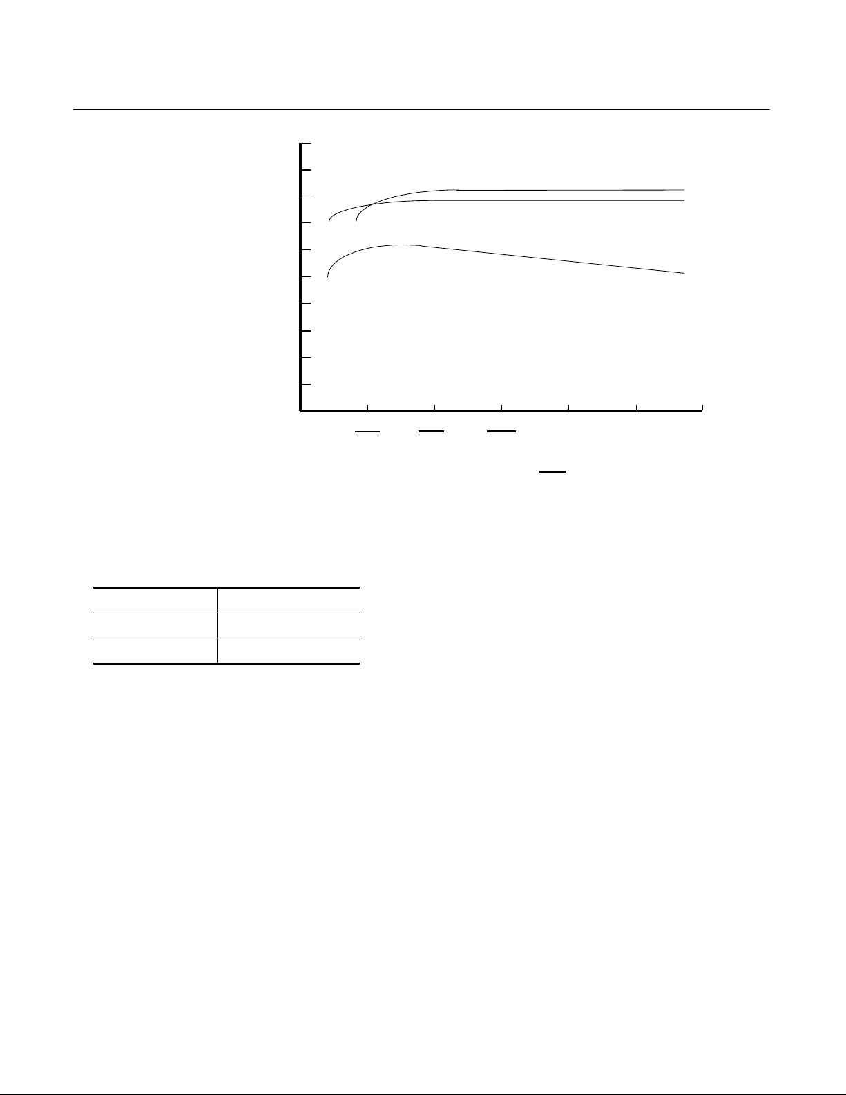
Model NGA2000 FID2
1.0
0.8
Instruction Manual
760002-A
July 2002
RESPONSE
(100 ppm CH
fullscale)
4
0.6
0.4
0.2
0
0
Figure 3-14. Typical Module Response vs. Burner Air Pressure Setting
Sample Pressure 5.6 psig / 38.61 hPa
Fuel Pressure 10.0 psig / 68.95 hPa
10
690
14
966
AIR PRESSURE
SAMPLE: 100 ppm CH
at 5 psig (344 hPa)
20
1376
psig
hPa
in N
4
2
Air Pressure 18.0 psig / 124.11 hPa
Table 3-1. Factory Defaults for Internal
Pressures
Rosemount Analytical Inc. A Division of Emerson Process Management Operation 3-11
Page 44

Instruction Manual
760002-A
July 2002
c. Binding
Model NGA2000 FID2
To achieve full coordination between
Analyzer Modules and associated I/O
Modules, the user must bind those
components together. (See the
Platform manual for binding
instructions.)
NOTE
If binding is attempted after ignition,
the flame may be extinguished. If
this occurs, it must be re-ignited
according to Section 3-3a on page
3-9.
d. Optimization
Although the module has been set up
for best operation at the factory,
settings can change and your
application may be different. The
following shows how to optimize the
operation of the FID2 for your
application.
1. Ignite the flame of the FID2 using
the startup procedure as above.
2. Verify that the mixed fuel supply
pressure at the Analyzer’s rear
panel bulkhead is between 49 and
50 psig.
3. Allow the Analyzer module
response to stabilize. Typically
allow 1 to 4 hours.
6. Set the internal burner air pressure
to between 965 to 1103 hPagauge (14 to 16 psig). The burner
air pressure must be kept constant
throughout the optimization
procedure.
7. Set the internal fuel pressure to
345 hPa-gauge (5 psig). Calibrate
the instrument as stated below.
8. Introduce the span gas and
monitor the reading until it is
stable. Increase the internal fuel
supply setting in the following
sequence: 600 hPa-gauge (8.7
psig), 625 hPa-gauge (9.1 psig),
650 hPa-gauge (9.4 psig), 675
hPa-gauge (9.8 psig), 700 hPagauge (10.1 psig), and 725 hPagauge (10.5 psig). Monitor the
reading at each fuel pressure
setting. Wait at least 2 minutes
between fuel setting changes.
Record all the readings.
9. Review the readings for each fuel
pressure setting. Select the fuel
pressure setting that produces a
reading that is within 1% from the
maximum. For this condition the
FID2 is operating at its optimized
plateau.
e. Shut Down Procedure
4. Select the desired range to
optimize. For best results use a
span gas with a concentration of
100 ppm CH4 or greater. This will
minimize the effects of the THC
contamination in the fuel and
burner air supply.
5. Set the internal sample pressure to
the desired operating level. The
sample pressure must be kept
constant throughout the
optimization procedure.
3-12 Operation Rosemount Analytical Inc. A Division of Emerson Process Management
If the FID2 is to be left in the powered
down state for any length of time
greater than a few hours, it is important
that the flame tower be dried out
before it cools off. This is to avoid
condensation causing corrosion. If the
sample contains halogenated
compounds this is even more
important.
During shutdown, always turn off fuel
gas first, then the air and sample
gases. The flame can also be turned
off by setting Ignition System Enable to
Page 45

Model NGA2000 FID2
Instruction Manual
760002-A
July 2002
"Off" in the Light Flame menu (under
Basic Controls). Subsequently,
remember to set Ignition System
Enable to "On" before attempting to
ignite the flame.
Flush the flame tower with burner air
for around an hour after the flame has
been turned off. Simply leave the
burner air flowing. When no evidence
of condensation can be seen in the
exhaust tubing, it is safe to switch off
the FID2 power.
If this precaution is not taken,
corrosion can occur making it hard or
impossible to light the flame.
f. Safety System
The FID2 Analyzer Module safety
system is entirely passive. The
pneumatic section of the analyzer is
designed to be intrinsically safe,
except for the flame tower itself which
is designed to be explosion proof.
Intrinsic safety design ensures that any
energy released in the hazardous area
(the pneumatic section) will not be
enough to ignite any hydrogen that
may have leaked. This is achieved by
limiting the voltage and the current in
all the circuitry that enters this area. It
is therefore essential that NO
modifications are done to the circuit
boards. Any repairs should be
performed at the factory where the
correct components will be used.
The flame tower is designed to be
explosion proof. This is achieved by
careful control of the spacing and
clearances of the assembly, and the
presence of the various flow restrictive
devices and the outlet flame arrestor. It
is essential that no changes be made
to this device that can impact any of
these clearances, and thus that any
repairs of the device are such as to
maintain its designed clearances. It is
recommended that any repairs of the
flame tower be performed in the
factory or at other authorized
Rosemount service centers.
A temperature safety system
activates when the burner flame
temperature exceeds 225
60 seconds. This will shut off the fuel
and display a message on the light
flame menu screen. After cooling to
below 225°C, the unit can be re-ignited
normally.
Verify that the proper fuel is being
used. Do not use H
configured for mixed fuel (H
Since the proper methane – nonmethane process should be run under
200ολσιC, you should not experience
this failure mode. If it occurs, contact
Rosemount Analytical Customer
Service Center (see page 6-1).
in a unit
2
°
C for over
/He).
2
Rosemount Analytical Inc. A Division of Emerson Process Management Operation 3-13
Page 46

Instruction Manual
760002-A
July 2002
Model NGA2000 FID2
3-4 ROUTINE OPERATION
The FID2 Analyzer Module is designed to
continuously analyze the sample stream.
Normally, it is never powered off except for
servicing or for a prolonged shutdown.
After binding (see Section 3-3c on page 3-
12) and calibration (see Section 3-9 on
page 3-32), proceed as follows:
Supply sample gas to the SAMPLE INLET.
Adjust external flow controller or throttle
valve so that flow discharged from the
BYPASS outlet is between 0.5 and 1.0
L/min. The reading on the SAMPLE
pressure gauge should be the same as
that used during adjustment of the span
control. Adjust, if necessary.
Adjust the Range Number setting.
If maximum sensitivity is required from the
FID2 Analyzer Module, use an optimum
combination of settings on the SAMPLE,
FUEL, and AIR pressure controllers.
Settings must be determined
experimentally, but the curves in Figure
3-12 on page 3-10, Figure 3-13 on page 310, and Figure 3-14 on page 3-11 may be
used as guides for the FID2 optimization
procedure in Section 3-3d on page 3-12.
The Analyzer Module will not allow the
user to increase the upper limit of a range
beyond the maximum range software
setting. To change the Maximum Range
value, select the following from the Main
Menu:
Main Menu
↓
Analyzer and I/O expert controls & setup…
↓
Analyzer Module Controls…
↓
Range settings…
Select “Range x upper limit”, and use the
arrow keys to scroll the indicated value.
The same applies for the “Range x lower
limit” value.
After initial startup, or startup following a
prolonged shutdown, the FID2 Analyzer
Module requires about one day's
continuous operation to stabilize. For
several days afterwards, calibrate daily.
The frequency of subsequent calibrations
can be reduced as experience dictates,
consistent with the accuracy requirements
of the particular application. Maximum
permissible interval between calibrations
depends on the analytical accuracy
required, and therefore cannot be
specified.
3-14 Operation Rosemount Analytical Inc. A Division of Emerson Process Management
Page 47

Model NGA2000 FID2
p
y
y
y
Instruction Manual
760002-A
July 2002
3-5 BASIC CONTROLS, SETUP AND STATUS
The following sections describe the basic
control of the analyzer and the viewing of
channel parameters. Examples of stepping
through the menus are shown so that the
user can become familiar with the
operation, keeping in mind that displays
and menu choices may be different
depending on actual analyzer configuration
and any customization of the menus.
a. Analyzer Channel Status
The analyzer status is displayed in the
Current measurement parameters
display.
To access the Current measurement
parameters display:
Main Menu [Measure (F1)]
↓
Measurement Mode [STATUS(F2)]
↓
Current measurement parameters
FID2 77.25 ppm
Flame condition: ON
Measurement range number: 1
Range change control: Local
Linearization mode: DISABLED
Analyzer operational state: STANDBY
Analyzer alarm state: NORMAL
Alarms reported: FAILURE
Current total variable updates per second: 22
HOME
Current measurement
ESCAPE
arameters
INFO
Figure 3-15. Current Measurement
Parameters Menu
This menu can also be accessed from
the “Main Menu” by pressing Status…
(F2).
To return to the previous menu, press
ESCAPE (F2). To go to the “Main
Menu”, press HOME (F1).
b. Single Component Display
The Measure menu that displays after
startup is the Single Component
display of the analyzer. If other
analyzer modules are connected to the
Platform, it is possible to display them
using the following steps to change the
channel of the single component
display:
From the Measure Mode display, press
Channel (F4) to change to the Single
Component Display of any other
installed Analyzer Modules.
Example:
Changing from FID2 (channel 1) to
CO
(channel 2).
2
Continue pressing Channel (F4) to
display the desired channel depending
on the installed analyzer configuration,
ultimately returning to the first channel.
FID2
77.25
0.00 Range: 1 100.00
Flame temperature: 145 C 100.0 280.0
Block temperature: 67.5 C 40.0 150.0
Sample pressure: 233.06 nPa 100.00 500.00
Raw signal: 495764 100000 900000
Displa
MLT/CH1/ R2
Status… Main… Channel BasicCal
2.50
0.00 Range: 2 5.00
Temperature: 37.0 C 0.0 100.0
Maintenance Requests: No
Any alarms: No
Operation: Ready
Displa
FID2
Status… Main… Channel BasicCal
77.25
0.00 Range: 1 100.00
Flame temperature: 145 C 100.0 280.0
Block temperature: 67.5 C 40.0 150.0
Sample pressure: 233.06 nPa 100.00 500.00
Raw signal: 495764 100000 900000
Displa
Status… Main… Channel BasicCal
ppm THC
% CO2
ppm THC
Figure 3-16. Single Component Display
Rosemount Analytical Inc. A Division of Emerson Process Management Operation 3-15
Page 48

Instruction Manual
y
y
[2]
[2]
760002-A
July 2002
Model NGA2000 FID2
c. Multi Component Display
If other analyzer modules are
connected to the Platform, it is
possible to display up to five using the
following steps to change from the
single component display to the multi
component display as follows:
From the single channel display
(Measure) press Display (F1) to
change to the Multi Component
Display of all other installed Analyzer
Modules.
Changing to the multi component
display can be done from each single
component display.
FID2
77.25
0.00 Range: 1 100.00
Flame temperature: 145 C 100.0 280.0
Block temperature: 67.5 C 40.0 150.0
Sample pressure: 233.06 nPa 100.00 500.00
Raw signal: 495764 100000 900000
Displa
>
Status… Main… Channel BasicCal
FID2
77.25
2.50
95.00
ppm THC
MLT/CH1
MLT/CH2
0.00 [1] 100.00
0.000
% CO2
0.00
ppm CO
ppm THC
5.00
250.00
Each bargraph shows the start and
end of the range for the respective
channel. The number in parentheses
indicates the number of the selected
range for that channel. (F.S. = full
scale)
(Display may look different depending
on installed analyzers.)
Use the Tags Off (F3) softkey to turn
the analyzer tags on or off.
To select a single channel display in
the multi channel display, enable the
select symbol (>) by pressing the F1
key or the ↓ key.
Then use the ↓ or ↑ key to select the
line for the desired channel. When the
desired channel is marked, select it for
single component display by pressing
the F1 key.
MLT/CH1
2.50
0.00 Range: 2 5.00
Temperature: 37.0 C 0.0 100.0
Maintenance-Request No
Any-alarms: N o
Operation: Ready
Displa
Status… Main… Channel BasicCal
% CO2
Select
Status… Tags Off LCDReset
Figure 3-17. Multi Component Display
3-16 Operation Rosemount Analytical Inc. A Division of Emerson Process Management
Page 49

Model NGA2000 FID2
3-6 BASIC CONTROLS
To access the Basic Controls menu:
Instruction Manual
760002-A
July 2002
Automatic range change control:
When enabled, the FID2 analyzer module
will change ranges automatically when the
present range is exceeded.
Measurement Mode [BasicCal (F5)]
Or
Main Menu
↓
Analyzer basic controls (calibration)
& setup…
FID2 77.25 ppm
Measurement range number: 1
Range upper limit: 10.0 ppm
Automatic range c hange control: Disabled
Span gas concentration: 90.0 ppm
Ranges with valid c alibration: 1&2
Calibration status: READY
If it won’t calibrate…
Flame condition: ON
Light flame…
HOME
-- Basic Controls --
ESCAPE
ZERO INFO
SPAN
Figure 3-18. Basic Controls Menu
The Basic Controls menu is used to set the
range, initiate and exit a quick start and
exit the sleep mode.
Measurement range number:
To select one of the four ranges of the
FID2 analyzer, Move the cursor to the
“Measurement range number:” line and
press the ↵ key. Change the range number
using the ↑ and ↓ keys and then press the
↵ key again to save the selection.
See Section 3-8a on page 3-21 to change
the begin and end concentration values for
each of the four ranges.
Span gas concentration
Allows setting of the calibration span gas
concentration. Default is the range upper
limit.
Ranges with valid calibration
Indicates the ranges that have passed a
recent calibration and are currently valid.
Calibration status
Indicates if the Analyzer Module is ready
for a calibration.
If it won’t calibrate
Displays a help screen. See Section
________ for calibration details.
Flame condition
Displays the current flame condition (ON or
OFF).
Light flame
Accesses the Light flame menu. See
Section 3-3a on page 3-9.
ZERO (F3)/SPAN (F4)
To perform a zero or span the analyzer,
flow the appropriate gas, select the correct
range and press the appropriate button. Do
a zero before span!
Rosemount Analytical Inc. A Division of Emerson Process Management Operation 3-17
Page 50

Instruction Manual
760002-A
July 2002
Model NGA2000 FID2
3-7 DISPLAY CONTROLS
Main Menu
↓
Display control…
FID2 77.25 ppm
Brightness: 70 %
Contrast: 23 %
Switch automati cally to “Measure” after: Never
Switch off backlight after: Never
Measure
-- Display Controls --
Figure 3-19. Display Controls Menu
The Display Controls menu is used to
adjust the display parameters.
NOTE
It is possible to change the brightness
and contrast values so that the display
is no longer visible. In such case, press
the F1 key twice to change to the multi
component display and then press the
F5 key for LCDReset.
These values can be reset to the defaults
from the Multi Channel display screen
(Section 3-5c on page 3-16) by pressing
LCDReset (F1) function key and from the
Start up display (Figure 3-8 on page 3-7)
by pressing LCDReset (F5).
Switch automatically to “Measure”
after:
This variable line allows setting of the
delay time before any selected menu
switches back to the Measure screen. The
selectable values are:
10 sec
30 sec
1 min
5 min
10 min
30 min
Never
Switch off backlight after:
This variable line allows setting of the
delay time before switching off the
backlight of the display screen. The
selectable values are:
Brightness and Contrast:
These controls can be adjusted to
accommodate the ambient lighting
conditions. The range of values are 20100% for brightness and 1-45% for
contrast.
10 sec
30 sec
1 min
5 min
10 min
30 min
Never
3-18 Operation Rosemount Analytical Inc. A Division of Emerson Process Management
Page 51

Model NGA2000 FID2
y
Instruction Manual
760002-A
July 2002
3-8 ANALYZER AND I/O, EXPERT
CONTROLS AND SETUP
The Expert Controls and Setup menus
provide for the configuration of system and
network I/O (SIO & DIO), and for the
configuration of various functions on the
FID2 Analyzer Module.
Main Menu
↓
Analyzer and I/O expert controls & setup…
FID2 77.25 ppm
Analyzer module controls…
System & network I/O module controls…
Analyzer module setup…
System & network I/O module setup…
(Note: Controls & setup are identical for MLT/TFID)
Measure
zer and I/O, Expert Controls and Setup --
-- Anal
Channel
Back…
Figure 3-20. Analyzer and I/O Expert Controls
and Setup Menu
FID2 77.25 ppm
Measurement range number: 1
Range upper limit: 100.0 ppm
Range settings…
Linearization: DISABLED
Range and functional c ontrol: Local
Zero/Span calibration…
Ranges with valid calibration: None
Physical measurements…
Flame condition: ON
Light flame…
HOME
-- Expert Controls --
ESCAPE
CAL INFO
CAL DATA
FID2 77.25 ppm
-- Analyzer and I/O, Expert Controls and Setup --
Analyzer module controls…
System & network I/O module controls…
Analyzer module setup…
System & network I/O module setup…
(Note: Controls & setup are identical for MLT/TFID)
Measure
Channel
Back…
FID2 77.25 ppm
-- System & Network I/O Module Controls --
System SIO module…
System DIO module…
Measure
FID2 77.25 ppm
Calibration gas list…
Calibration parameters…
Concentration alarms…
Gas measurement parameters…
Analyzer parameter list…
Physical measurement parameters…
Displayed parameters…
Analyzer tag: FID2
HOME
-- Analyzer Module Setup --
ESCAPE STORE
<<<
System & network I/O module controls… and System & network I/O module setup… are the same.
Figure 3-21. Analyzer and I/O Expert Controls and Setup Menu - Sub Menus
Back…
>>>
INFO
Rosemount Analytical Inc. A Division of Emerson Process Management Operation 3-19
Page 52

Instruction Manual
p
760002-A
July 2002
Model NGA2000 FID2
NOTE
Whenever the “Channel” tag appears
above the F3 key, pressing F3 will
switch to any other installed analyzer
modules, one after the other and eventually back to the FID2 module. When
activating any other installed module,
the menus will be different depending
on that module. See each module’s
manual for a description of those
menus.
In the “Analyzer and I/O expert controls
and setup” menu, select “Analyzer module
control…” . The “Expert Controls” menu
will display as shown in Figure 3-22 below.
FID2 77.25 ppm
Measurement range number: 1
Range upper limit: 100.0 ppm
Range settings…
Linearizer: DISABLED
Range and functional control: Local
Zero/Span calibration…
Ranges with valid calibration: None
Physical measurements…
Flame condition: ON
Light flame…
HOME
-- Ex
ert Controls --
CAL
CAL DATA
INFOESCAPE
Figure 3-22. Expert Controls Menu
Measurement range number
To select one of the four ranges of the
FID2 analyzer.
Range settings
See Section 3-8a on page 3-21.
Linearizer
See Section 3-8e on page 3-24.
Range and functional control
Local -Range control by the menus.
Inputs I/O module - Range control by
remote communication.
Program I/O module - Range control by the
I/O module
Zero/Span calibration
See Section 3-12 on page 3-36.
Ranges with valid calibration
Indicates the ranges that have passed a
recent calibration and are currently valid.
Physical measurements
See Section 3-8b on page 3-21.
3-20 Operation Rosemount Analytical Inc. A Division of Emerson Process Management
Page 53

Model NGA2000 FID2
g
y
Instruction Manual
760002-A
July 2002
a. Range Settings
To change the upper and lower limit for
each of the four ranges, select Range
Settings from the Expert Controls
menu as follows:
Main Menu
↓
Analyzer and I/O expert controls &
setup…
↓
Analyzer module controls…
↓
Range settings…
FID2 77.25 ppm
Minimum range: 10.0 ppm
Maximum range: 5000 ppm
Range 1 lower limit: 0.0 ppm
Range 1 upper limit: 100.0 ppm
Range 2 lower limit: 0.0 ppm
Range 2 upper limit: 10.0 ppm
Range 3 lower limit: 0.0 ppm
Range 3 upper limit: 5000.0 ppm
Range 4 lower limit: 0.0 ppm
Range 4 upper limit: 5000.0 ppm
HOME
ESCAPE
-- Ran
e Settings --
INFO
b. Physical Measurements
Use the Physical Measurements menu
to view various conditions of the FID2
module and to adjust the bypass flow
limits.
Main Menu
↓
Analyzer and I/O expert controls &
setup…
↓
Analyzer module controls…
↓
Physical measurements…
FID2 77.25 ppm
Sample pressure: 3.4 hPa
Fuel supply pressure: 2.7 hPa
Burner air pressure: 124.1 hPa
Flame temperature: 79.6 C
Block temperature:
HOME
sical Measurements --
-- Ph
INFOESCAPE
Figure 3-23. Range Settings Menu
To change any of the limits, move the
cursor to the desired line and press the
↵ key. Change the limit value using the
↑ and ↓ keys and then press the ↵ key
again to save the selection.
Press the ESCAPE (F2) softkey before
pressing the ↵ key to restore the
previous value.
The Range Settings menu is also
accessible from the Gas Measurement
Parameters as follows:
Main Menu
↓
Analyzer and I/O expert controls &
setup…
↓
Analyzer module setup…
↓
Gas measurement parameters…
↓
Range settings…
Figure 3-24. Physical
Measurements
Rosemount Analytical Inc. A Division of Emerson Process Management Operation 3-21
Page 54

Instruction Manual
p
760002-A
July 2002
Model NGA2000 FID2
c. Concentration Alarms
Use the Concentration Alarm Setup
menu to establish or change the
alarms for the sample gas
concentration measurement.
Main Menu
↓
Analyzer and I/O expert controls &
setup…
↓
Analyzer Module Setup…
↓
Concentration alarms…
FID2 77.25 ppm
Alarm generation is: On
Level for Low-Low alarm: 0.000
Level for Low alarm: 0 .000
Level for High alarm: 9.000
Level for High-High alarm: 10.000
Alarm delay: 1.0 s
Low-Low alarm: On
Low alarm: On
High alarm: On
High-High alarm: On
HOME
-- Concentration Alarm Setu
ESCAPE
ACKN
--
To change the alarm limits, move the
cursor to the desired line and press the
↵ key. Change the limit value using the
↑ and ↓ keys and then press the ↵ key
again to save the selection.
Press the Back (F2) button before
pressing the ↵ key to restore the
previous value.
Alarm delay
Set the alarm delay for the desired
time delay after the concentration
value exceeds the limit before the
alarm is activated.
Alarm generation is:
This setting establishes the generation
of alarms as “Off,” “On,” or “On (Hold
Alarm).” The “On (Hold Alarm)” setting
provides that the alarm will remain
active even after the gas concentration
returns below the appropriate level
until the ACKN button is pressed or it
is reset from the remote I/O.
Figure 3-25. Concentration Alarm
Setup Menu
NOTE
Calibration parameters are described in Section 3-9 on page 3-32.
ACKN
Press the F3 button to acknowledge
and reset any alarm.
3-22 Operation Rosemount Analytical Inc. A Division of Emerson Process Management
Page 55

Model NGA2000 FID2
p
Instruction Manual
760002-A
July 2002
d. Linearization Parameters
Linearization parameters allows the
establishment of linearizer coefficients
and the assignment of coefficient sets
to individual ranges. The linearization
parameters are only used by qualified
service personnel for troubleshooting.
The linear polynomials act over a
range (not the same as the
measurement range). The system
uses the linearizer polynomial
appropriate for the measurement
range chosen. This is the polynomial
with the next higher range. It is,
however, possible to specify that the
analyzer use a wider range polynomial.
Note that the use of different
polynomials on different ranges will
give different readings on a new range.
To access the Linearization
parameters menu:
Main Menu
↓
Analyzer and I/O expert controls &
setup…
↓
Analyzer module setup…
↓
Gas measurement parameters…
FID2 77.25 ppm
Linearization parameters…
Response time/delay parameters…
Range settings…
Automatic range change parameters…
Units…
Linearization functions…
-- Gas measurement
arameters --
FID2 77.25 ppm
Range 1 linearizer: Disabled
If enabled, uses curve no.: 1
Range 2 linearizer: Disabled
If enabled, uses curve no.: 2
Range 3 linearizer: Disabled
If enabled, uses curve no.: 3
Range 4 linearizer: Disabled
If enabled, uses curve no.: 4
Set coefficients…
HOME
-- Linearization Parameters --
ESCAPE
INFO
Figure 3-27. Linearization
Parameters Menu
From the Linearization Parameters
menu, select Set coefficients…
Coefficients may be edited for custom
curves.
CLD 7.50 ppm
A0 coefficient: 0.000000
A1 coefficient: 1.000000
A2 coefficient: 0.000000
A3 coefficient: 0.000000
A4 coefficient: 0.000000
Curve upper limit: 10.0 ppm
Curve over-range: 5.0 %
Curve under-range: 5.0 %
Status: Disabled
HOME
Linearity coefficients
ESCAPE
Curve 1
NEXT LAST
INFO
Figure 3-28. Linearity Coefficients
Menu
Edit the polynomial coefficients as
desired. Make sure that the curve
upper limit is correct. This is the limit of
the range that this polynomial will
support.
The last line (Status) selects whether
the curve is in use.
HOME
ESCAPE
INFO
Use the NEXT (F3), LAST (F4), and
BACK (F4) softkeys to access all four
Figure 3-26. Gas Measurement
curves.
Parameters Menu
From the Gas measurement
parameters menu, select Linearization
parameters…
Rosemount Analytical Inc. A Division of Emerson Process Management Operation 3-23
Page 56

Instruction Manual
y
y
760002-A
July 2002
e. Linearization Functions
The linearization functions allow the
primary variable output to be linearized
by either a polynomial of up to 20 set
points, or by midpoint piecewise
correction with up to three midpoints.
Main Menu
Analyzer and I/O expert controls &
Analyzer Module Setup…
Gas Measurement Parameters…
Linearization Functions…
FID2 77.25 ppm
Polynomial setup…
Midpoint correction setup…
Use the polynomial setup to generate a linearizing
polynomial from up to 20 gases. With more than 6 gases
it will produce a fourth order polynomial linearizer.
Use the midpoint correction for a piecewise-linear final
correction, to bring up to three points precisely onto
the curve.
HOME
Figure 3-29. Linearization Functions
-- Linearization Functions --
ESCAPE
↓
setup…
↓
↓
↓
Menu
INFO
Model NGA2000 FID2
Select the range to linearize.
Make sure that the span gas value is
correct and set into the “Correct span
gas” line.
Choose whether to define the gas
concentrations as absolute values
(ppm) or as a percent of the span gas
(Percent of span gas) in the “Gas
values shown as” line.
Percent would be used if the span gas
is being diluted with a mixing device.
Choose the “Gas concentrations…”
submenu to enter up to 20 points for
each range.
FID2 77.25 ppm
Gas value: 1.00
Raw reading: 0.9 ppm
Linearized value: 1.0 ppm
Gas value: 2.00
Raw reading: 1.9 ppm
Linearized value: 2.0 ppm
Point to be measured: Point 1
zer function: READY
Anal
HOME
Figure 3-31. Gas Concentrations Menu
Gas concentrations
ESCAPE
Point 1
Point 2
DATA
NEXT
INFO
Polynomial Set Up
Use the polynomial set up to generate
a linearizing polynomial from up to 20
gases. With more than 6 gases, it will
produce a fourth order polynomial
linearizer.
From the Linearization functions menu,
select Polynomial set up…
FID2 77.25 ppm
Range to be li nearized: 1
Current span gas: 90.0 ppm
Calculated pol ynomial order: 4
Gas value shown is: ppm
Gas concentrations…
-- Pol
nomial Setup --
Enter the gas value for the desired
point as ppm or percent of scan range
in accordance with the previous choice
made for the “Gas values shown as.”
Choose the point to be measured from
the “Point to be measured” line.
At each point in succession, flow the
gas of the correct value and, when the
reading is stable, press the “DATA”
button to record the gas value and raw
reading for each point.
Move to the next two points with the
NEXT (F4) button and move
Analyzer function: READY
HOME
ESCAPE
CALC
INFO
Figure 3-30. Polynomial Setup Menu
3-24 Operation Rosemount Analytical Inc. A Division of Emerson Process Management
backwards with the ESCAPE (F2)
button. Pressing ESCAPE from the
Point 1 menu returns to the previous
menu.
Page 57

Model NGA2000 FID2
y
Instruction Manual
760002-A
July 2002
After the desired number of points has
been measured and recorded, return
to the “Polynomial set up” menu and
press the “CALC” button.
The analyzer will calculate the best fit
polynomial and store it as the
coefficients in the current range’s
linearizer function.
The order or the polynomial is
optimized based on the number of data
points provided. At least 7 points are
required for a fourth-order polynomial
correction. The results can be modified
with the “Midpoint correction” also
provided. See Midpoint Correction
Setup below.
CAUTION.
The linearization curve must be
monotonic. If it is not, the calibration routine will fail and the analyzer
will not calibrate. Test this by
copying the values of the linearization coefficients into a spreadsheet
program and plotting the results.
Main Menu
↓
Analyzer and I/O expert controls &
setup…
↓
Analyzer module setup…
↓
Gas measurement parameters…
↓
Linearization functions…
↓
Midpoint correction set up…
FID2 77.25 ppm
Correction: DISABLED
Point being mesured: Point 1
Point 1 gas concentration: 2.50 ppm
Point 2 gs concentration: 5.00 ppm
Point 3 gas concentration: 7.50 ppm
Point 1 reading: 2.52 ppm
Point 2 reading: 5.12 ppm
Point 3 reading: 7.56 ppm
Span gas value: 10.00 ppm
Anal
zer function: READY
HOME
Midpoint correction setup
Point 1
ESCAPE
SET
RANGE 2
INFO
Figure 3-32. Midpoint Correction Setup
Menu
First, disable the correction.
Set the point being measured to
Point 1.
The analyzer does not test for
monotonicity when it spans, but this
test may not catch all possible errors.
Monotonic means that the curve does
not change direction as the gas
concentration increases.
Midpoint Correction Set Up
This function allows the adjustment of
the primary variable output into a
precise value using up to three
midpoints. It does this with a
piecewise-linear algorithm that occurs
after and in addition to any polynomial
linearization.
The correction can be performed
individually for each range.
Then enter the first midpoint gas value,
run the gas, and when stable, press
“SET.” “Point 1 reading” will show the
actual reading, but the analyzer will
adjust it to the correct value.
Repeat the above steps with the
second and third points as desired.
When complete, se the “Correction:”
line to “ENABLED” to activate the
correction.
CAUTION.
Make sure that the corrections are not
excessive. If the correction is too excessive, the calibration routine will fail
and calibration of the analyzer will not
be possible.
Rosemount Analytical Inc. A Division of Emerson Process Management Operation 3-25
Page 58

Instruction Manual
760002-A
July 2002
f. Response Time
The response time menus allows the
setting of the primary analyzer variable
t90 times, the LON update rate and the
output delay time as follows:
Model NGA2000 FID2
The t90 Time adjusts the filtering or
damping factor for the concentration
outputs for each range. They are
adjustable from 0.1 to 30 seconds with
a default of 3.0 seconds.
Main Menu
↓
Analyzer and I/O expert controls &
setup…
↓
Analyzer module setup…
↓
Gas measurement parameters…
↓
Response time/delay parameters…
FID2 77.25 ppm
Range 1 t90 time: 3.0 s
Range 2 t90 time: 3.0 s
Range 3 t90 time: 3.0 s
Range 4 t90 time: 3.0 s
LON update time: 10 per sec
Output delay time: 0.0 s
HOME
Response time/delay Parameters
ESCAPE
Figure 3-33. Response time/delay
Parameters
The LON Update Rate is the rate at
which the analyzer communicates over
the system network. It is adjustable to
“ASAP” (the fastest rate that the
network communicates), “10 per sec,”
and “1 per sec.”
The Output Delay Time establishes the
delay for the DIO and analog outputs
to respond to a change in
concentration value. It is adjustable
from 0.0 to 30.0 seconds.
To change a value, move the cursor to
the desired line and press the ↵ key.
Change the value using the ↑ and ↓
keys and then press the ↵ key again to
save the selection. Press the Back
(F2) button before pressing the ↵ key
to restore the value.
3-26 Operation Rosemount Analytical Inc. A Division of Emerson Process Management
Page 59

Model NGA2000 FID2
g
g. Automatic Range Change
This menu function allows the setting
and enabling of the automatic range
change for each of the four ranges.
The automatic range switching for
increasing values is effective at the
upper range limit of each range, while
for decreasing values it is the next
lower range limit times the hysteresis
percent times the upper range limit.
Instruction Manual
760002-A
July 2002
Set the desired hysteresis level in the
range of 10% to 50% which is applied
to each range transition. (20% is the
default setting.) Enable the desired
ranges and enable the automatic
range change control.
To view the actual switching levels,
select the submenu “Actual switch
levels…”.
Main Menu
↓
Analyzer and I/O expert controls &
setup…
↓
Analyzer module setup…
↓
Gas measurement parameters…
↓
Automatic range change
parameters…
FID2 77.25 ppm
Actual switch levels…
Switch level hysteresis: 20 %
Usage of range –1: Enabled
Usage of range –2: Enabled
Usage of range –3: Enabled
Usage of range –4: Enabled
Automatic range change control: Enabled
Absolute range upper limit: 10000 ppm
Absolute range lower limit: 10.0 ppm
Measure
-- Automatic Ran
e Control --
Back…
Figure 3-34. Automatic Range Control
Menu
FID2 77.25 ppm
-- Actual Switch Levels --
Range – 1 up: 10.0 ppm
Range – 1 down: -1000000 ppm
Range – 2 up: 25.0 ppm
Range – 2 down: 9.0 ppm
Range – 3 up: 100.0 ppm
Range – 3 down: 22.5 ppm
Range – 4 up: 250.0 ppm
Range – 4 down: 90.0 ppm
Measure
Back…
Figure 3-35. Actual Switch Levels
Menu
Rosemount Analytical Inc. A Division of Emerson Process Management Operation 3-27
Page 60

Instruction Manual
760002-A
July 2002
Model NGA2000 FID2
h. Display Units
This menu function is used to set the
displayed units for the various
parameters. This only affects the
displayed values. All outputs are in the
basic SI units which, for example, for
pressure is hPa. Gas concentration
values are for all ranges. Individual
ranges cannot be set to different units.
Main Menu
↓
Analyzer and I/O expert controls &
setup…
↓
Analyzer module setup…
↓
Gas measurement parameters…
↓
Units…
FID2 77.25 ppm
Gas measurement units: ppm
Pressure measurement units: hPa
Temperature measurement units: C
ppm to mg/Nm3 conversion factor: 1.000
Lower explosion limit (LEL): 0.00 %
Upper explosion limit (UEL) 0.00 %
Variable are still sent as the basic SI unit.
HOME
-- Units --
ppm to mg/Nm3 conversion factor:
3
The ppm to mg/Nm
conversion factor
in the range of 1 to 100000 according
to the formula:
mg/Nm3 =
Molecular weight
MW
NO 30.0
NO
46.0
2
CO 28.0
SO
O
64.1
2
32.0
2
Lower explosion limit (LEL):
This is the minimum concentration of
the sample gas at which the flammable
vapors will ignite.
Upper explosion limit (UEL):
This is the maximum concentration of
the sample gas at which the flammable
vapors will sustain burn.
INFOESCAPE
Figure 3-36. Display Units Menu
Select the desired parameter and
change the units as follows:
Gas measurement units:
ppm, %, ppb, mg/Nm3
Pressure measurement units:
hPa, psig
Temperature measurement units:
C, F
3-28 Operation Rosemount Analytical Inc. A Division of Emerson Process Management
Page 61

Model NGA2000 FID2
y
Instruction Manual
760002-A
July 2002
i. Physical Measurements & Pressure
Limits
This menu is used to display the
physical diagnostic parameters of the
FID2 analyzer and to set the various
pressure limits.
Main Menu
↓
Analyzer and I/O expert controls &
setup…
↓
Analyzer module setup…
↓
Physical measurements
parameters…
FID2 77.25 ppm
Sample capillary pressure: 38.6 hPa
Sample capillary pressure was: 40.0 hPa
Fuel supply pressure: 69.0 hPa
Fuel supply pressure was: 70.5 hPa
Burner air pressure: 124.1 hPa
Burner air pressure was: 125.0 hPa
Pressure limits…
Temperature limits…
sical Measurements --
-- Ph
Choose the “Pressure limits…” to view
and set the alarm pressure limits for
the sample, fuel and air.
FID2 77.25 ppm
Sample capillary upper limit: 500 hPa
Sample capillary lower limit: 10 hPa
Fuel pressure upper limit: 1500 hPa
Fuel pressure lower limit: 50 hPa
Burner air upper limit: 1500 hPa
Burner air lower limit: 100 hPa
HOME
-- Pressure Limits --
ESCAPE
INFO
Figure 3-38. Pressure Limits Menu
Choose the “Temperature limits…” to
view and set the alarm temperature
limits for the block, flame and preamp.
FID2 77.25 ppm
Block upper limit: 150 C
Block lower limit: 40.0 C
Flame upper limit: 280 C
Flame lower limit: 100 C
Preamp upper limit: 50.0 C
Preamp lower limit: 30.0 C
-- Temperature Limits --
HOME
ESCAPE MORE
Figure 3-37. Physical
Measurements Menu
In the Physical measurements display,
the normal values for the displayed
values are:
Sample capillary pressure: 38.6 hPa
Fuel supply pressure: 69.0 hPa
Burner air pressure: 124.1 hPa
The historical (last) values are
displayed below each parameter.
See Section 3-3b on page 3-10 for
setting the internal pressures and 3-3d
on page 3-12 for optimization.
INFO
HOME
ESCAPE
INFO
Figure 3-39. Temperature Limits Menu
Press MORE to display Physical
Measurement parameters
temperatures.
FID2 77.25 ppm
Block temperature: 80 C
Block temperature was: 0.0 C
Flame temperature: 78.6 C
Flame temperature was: 0.0 C
Preamplifier temperature: 35.8 C
Preamplifier temperature was: 0.0 C
HOME
-- Physical Measurement Parameters --
ESCAPE
INFO
Figure 3-40. Physical Measurement
Parameters (Temperature Limits) Menu
Rosemount Analytical Inc. A Division of Emerson Process Management Operation 3-29
Page 62

Instruction Manual
play
760002-A
July 2002
Model NGA2000 FID2
j. Single Component Display
Parameters
This function and menu is used to
establish the parameters to be
displayed on the single component
display.
Main Menu
↓
Analyzer and I/O expert controls &
setup…
↓
Analyzer Module Setup…
↓
Displayed parameters…
FID2 77.25 ppm
-- Dis
ed Parameters --
First line’s parameter: Flame temperature
Second line’s parameter: Block temperature
Third line’s parameter: Sample pressure
Fourth line’s parameter Raw signal
Displayed concentration digits: 6
Digits after decimal point: 2
HOME
Figure 3-41. Displayed Parameters
Menu
In this menu, the components
displayed in the Single Component
Display can be changed.
Block temp
Displays the detector block
temperature with a bargraph.
Preamp temperature
Displays the preamplifier detector
temperature with a bargraph.
Flame status
Displays the current flame status, ON
or OFF
Auto ignite status
Displays the status of the auto-ignite
as Enabled or Disabled.
t90 time
Displays the t90 response time for the
displayed range with a bargraph.
Delay time
Displays the output delay time setting
with a bargraph.
INFOESCAPE
Calibration status
Displays the calibration status:
READY, Calibration
Raw signal
Displays the raw concentration output
of the detector before any linearization
or other correction.
The concentration value precision and
number of digits can also be set from
Operational state
Standby, Calibration, Ready
this menu. This does not change the
inherent precision of the analyzer.
Health
Analyzer status: NORMAL, Check
Select a line and press the ↵ key. To
change the value use the ↑ and ↓
keys. The values will scroll through the
allowable selections as follows:
Validity
Validity of the concentration
measurement: Valid, Invalid (Goes to
Valid after a successful calibration).
Sample pressure
Displays the sample pressure with a
bargraph.
Air pressure
Displays the current burner air press
with a bargraph.
Flame temperature
Displays the flame temperature with a
bargraph.
Fuel pressure
Displays the current fuel press with a
bargraph.
3-30 Operation Rosemount Analytical Inc. A Division of Emerson Process Management
Page 63

Model NGA2000 FID2
g
y
Instruction Manual
760002-A
July 2002
k. Configuration Storage
Analyzer Module Setup Parameters
It is possible to store the expert FID2
Analyzer Module set up parameters so
that if the configuration is damaged is
some way, the variables can be
restored.
Main Menu
↓
Analyzer and I/O expert controls &
setup…
↓
Analyzer Module Setup…
From the “Analyzer Module Setup”
menu press STORE (F3) to access the
Store/Restore User Settings menu.
FID2 77.25 ppm
-- Store/Restore user settin
Are you sure?
STORE button saves various user settings
for later usage.
RESTORE will restore the previously saved
user settings.
HOME
ESCAPE
STORE
s --
RESTORE
Figure 3-42. Store/Restore User
Settings Menu
Press the STORE (F3) button to store
the current diagnostic parameters.
Press the RESTORE (F4) button to
restore the analyzer module to the
previously stored diagnostic
parameters.
INFO
Diagnostic Data
The diagnostic data and certain
physical measurement parameters can
be stored or restored. The stored
values are shown in various menus as
the “was” values.
Main Menu (F5 – MFG Data)
↓
Analyzer Module manufacturing
data…
FID2 77.25 ppm
-- Anal
zer manufacturing data --
More…
Minimum range: 10.0 ppm
Maximum range: 5000 ppm
Measured gas: THC
Sample capillary: 13.5 ml/min @ 5psig
HOME
ESCAPE
RESET
STORE
INFO
Figure 3-43. Analyzer
Manufacturing Data Menu
From the “Analyzer manufacturing
data” menu press STORE (F3) to
access the “Store historical data”
menu.
FID2 77.25 ppm
Are you sure?
STORE will copy current diagnostic data into the
historical (“Was”) variables, overwri ting whatever is
currently there.
If you are sure, press STORE again.
RESTORE will do the opposite and move data from
historical to current values.
If you are sure, press RESTORE.
HOME
-- Store historical data --
ESCAPE
STORE
RESTORE
INFO
Figure 3-44. Store Historical Data
Menu
Press the STORE (F3) softkey to store
the current diagnostic parameters.
Press the RESTORE (F4) softkey to
restore the analyzer module to the
previously stored diagnostic
parameters.
Rosemount Analytical Inc. A Division of Emerson Process Management Operation 3-31
Page 64

Instruction Manual
760002-A
July 2002
3-9 CALIBRATION METHODS
Model NGA2000 FID2
a. Overview
The FID2 analyzer module may require
periodic calibration with known zero
and span gases in order to maintain a
desire level of analytical accuracy. It is
recommended, after initial startup, that
the FID2 Analyzer Module is calibrated
at least once every 24 hours. This
practice should continue until evidence
indicates that some other interval is
more appropriate depending on the
analytical accuracy required.
Calibration is the process of flowing
know zero or span calibration gas into
the analyzer for a specified period
(averaging time), after which the
analyzer will automatically set its zero
or span factors so that the
concentration measurement equals the
calibration gas value. A limit can be
set, beyond which any attempt by the
analyzer to reset its concentration
measurement will cause a warning
alarm. In this case, user intervention
would be required to reset the alarm
and attempt another calibration.
There are three methods for
performing a calibration with the FID2
Analyzer Module and NGA Platform:
Basic controls calibration, Expert
controls calibration, and System
calibration.
c. Expert Controls Calibration
See Section 3-12 on page 3-36.
This method allows the user to perform
a zero or span calibration for each of
the four ranges, enable or disable the
calibration adjustment limits, view the
results, and view or change the
Factors that the analyzer uses to
adjust the zero and span concentration
reading. This method uses calibration
parameters established in the module
setup menus. (See Section 3-10 on
page 3-33)
d. System Calibration And Setup
This method allows the user to
establish complex automated
calibration sequences for modules
bound to the Platform. This is fully
described in the Platform manual.
NOTE
If zero calibration is done with other
than a true zero gas followed by a
span calibration, it may be necessary to repeat the calibration. This
is due to the slope/intercept effect
where the subsequent span calibration may change the zero crossing
point.
b. Basic Controls Calibration
See Section 3-11 on page 3-35.
This method allows the user to input a
span calibration gas value and perform
a zero or span calibration for each of
the four ranges. This method uses
calibration parameters established in
the module setup menus. (See Section
3-10 on page 3-33)
3-32 Operation Rosemount Analytical Inc. A Division of Emerson Process Management
Page 65

Model NGA2000 FID2
Instruction Manual
760002-A
July 2002
3-10 CALIBRATION SETUP
a. Gas List
This menu is used to set the
concentration values of the calibration
gases for each range. These values
are used for all calibrations except in
Basic where the span gas can be
entered for a quick manual calibration.
Main Menu
↓
Analyzer and I/O expert controls &
setup…
↓
Analyzer Module Setup…
↓
Calibration gas list…
FID2 77.25 ppm
Zero gas – range 1: 0.00 ppm
Span gas – range 1: 10.00 ppm
Zero gas – range 2: 0.00 ppm
Span gas – range 2: 10.00 ppm
Zero gas – range 3: 0.00 ppm
Span gas – range 3: 10.00 ppm
Zero gas – range 4: 0.00 ppm
Span gas – range 4: 10.00 ppm
Calibration gas HC response factor: 1.00
HOME
-- Calibration Gas List --
b. Response Factor
THE FID2 provides selective response
to hydrocarbons (organic compounds).
The FID2 signal is approximately
proportional to the number of carbon
atoms in the sample gas. Depending
on the molecular structure of the gas,
the FID2 can show a different
response that is compensated by the
Response Factor.
The ions in the flame are created by
the oxidation process. Pre-oxidized
hydrocarbons thereby contribute less
to the ion creation and the resulting
FID signal. The response of preoxidized hydrocarbons is therefore less
than that of non-oxidized hydrocarbons
like propane. The higher the oxidation
level of the carbon atom in the
molecule, the lower the response of
the substance.
Since Response Factors are analyzer
design specific, each type of analyzer
uses different factors. Response
Factors for the FID2 are relative to
INFOESCAPE
methane.
Figure 3-45. Calibration Gas List Menu
From the “Analyzer Module Setup”
menu choose “Calibration Gas List”
menu.
Choose the desired calibration gas line
and enter the desired concentration
value.
The “Calibration…” submenu provides
quick access to the Expert Controls
Calibration menu. See Section 3-12 on
page 3-36.
Common Response Factors for the
FID2 are shown in Table 3-2 below.
Substance Response Factor
Methane 1.00
Ethane 1.90
Propane 3.00
Table 3-2. Calibration Gas HC Response
Factors
Rosemount Analytical Inc. A Division of Emerson Process Management Operation 3-33
Page 66

Instruction Manual
760002-A
July 2002
Model NGA2000 FID2
c. Calibration Parameters
This menu provides various parameter
settings for all calibration performed
from Basic or Expert modes.
Main Menu
↓
Analyzer and I/O expert controls &
setup…
↓
Analyzer Module Setup…
↓
Calibration parameters…
FID2 77.25 ppm
Calibration adjustment limits: Enabled
Calibration averaging time: 5 s
Calibration failure alarm: No
Cal failure error allowed: 50 %
Calibration time out: 60 s
Zero ranges: TOGETHER
Span ranges: SEPARATELY
HOME
-- Calibration Parameters --
Figure 3-46. Calibration Parameters
Menu
Calibration adjustment limits:
Set to “Disable” to recover from a
calibration failure.
Calibration averaging time:
Sets the time used by the analyzer to
average its reading during calibration.
A longer time will give a better
calibration.
Calibration failure alarm:
When turned on (Yes), issues a
warning if the analyzer has to change
its calibration by more than the Cal
Failure Error, if warning alarms are
enabled.
Cal failure error allowed:
The percentage by which the
calibration can change before an alarm
is triggered if the Calibration Failure
Alarm is enabled.
Calibration time out:
Sets how long the analyzer will wait for
the signal to stabilize before issuing a
Warning.
Zero (Span) ranges:
Used to select whether to calibrate
ranges TOGETHER or SEPARATELY.
If together, zeroing or spanning will go
INFOESCAPE
through each range one by one. If the
change required is too great, it will fail
and send an alarm if warning alarms
are enabled. In this case, Disable
Calibration Adjustment Limits and try
again. First check that the calibration
gases are correct.
If non-zero gases are used, or the
changes are great, zero and span may
have to be repeated a few times.
3-34 Operation Rosemount Analytical Inc. A Division of Emerson Process Management
Page 67

Model NGA2000 FID2
y
Instruction Manual
760002-A
July 2002
3-11 BASIC CONTROLS CALIBRATION
This method allows the user to input a
span calibration gas value and perform
a zero or span calibration for each of
the four ranges.
Main Menu
↓
Analyzer basic controls (calibration)
& setup…
↓
Span gas concentration…
FID2 77.25 ppm
Are you sure?
You must have zero gas flowing through the analyzer.
Calibration time: 0 s
Measurement range number: 1
Zero ranges: TOGETHER
Calibration status: READY
Error message for last zero: CAL OK
HOME
-- Anal
zer Zero --
Figure 3-47. Analyzer Zero Menu
In the “Basic Controls” menu, move the
cursor to the “Span gas concentration:”
line and set the correct value for the
calibration span gas. The zero gas is
assumed to be 0.00 ppm.
Begin flowing the calibration gas (zero
or span) and allow time for the
analyzer to stabilize on the gas.
Press the appropriate ZERO (F3) or
SPAN (F4) softkey to display the
calibration menu as shown below.
The “Calibration status” must be
READY in order to initiate a calibration.
Verify that the desired measurement
range is active. If not, press ESCAPE
(F2) to return to the previous menu
and change the range.
The “Zero (Span) ranges” tag indicates
if the ranges will be calibrated together
or separately. See Section 3-10c on
page 3-34 to change this.
The “Calibration time” begins to count
after the calibration is started to show
the elapsed time.
Press the ZERO (F3) [SPAN (F4)]
INFOESCAPE ZERO
button to begin the calibration. The
“Calibration status” will display
ZEROING-WAIT [SPANNING-WAIT]
and the “Calibration time” clock will
count the seconds. After the signal has
stabilized the calibration will finish. If
the signal does not stabilize within the
timeout period (See Section 3-10c on
page 3-34), the calibration will fail and
another attempt will be started
automatically. Make sure that the
proper calibration gas is flowing.
Rosemount Analytical Inc. A Division of Emerson Process Management Operation 3-35
Page 68

Instruction Manual
p
g
p
j
760002-A
July 2002
Model NGA2000 FID2
3-12 EXPERT CONTROLS CALIBRATION
This method allows the user to perform
a zero or span calibration for each of
the four ranges, enable or disable the
calibration adjustment limits, view the
results, and view or change the
Factors that the analyzer uses to
adjust the zero and span concentration
reading.
Main Menu
↓
Analyzer and I/O expert controls &
setup…
↓
Analyzer Module Controls…
FID2 77.25 ppm
Measurement range number: 1
Range upper limit: 10.0 ppm
Range settings…
Linearizer: DISABLED
Range and functional control: Local
Zero/Span calibration…
Ranges with valid calibration: None
Physical measurements…
Flame condition: ON
ht flame…
Li
HOME
ESCAPE INFOCAL DATACAL
-- Ex
ert Controls --
Figure 3-48. Expert Controls Menu
From the “Expert Controls” menu,
select the “Zero/span calibration”
submenu.
Set the desired measurement range
number to be calibrated.
The zero and span gas concentrations
set in the calibration gas values menu
are displayed. See Section 3-10 on
page 3-33 to change the values.
The sample flow rate is displayed
along with the raw measurement
signal. The sample flow rate should be
in the range of 200 – 2200 ml/min. The
raw measurement signal can be used
to set the FACTORS described in
Section .
The “Measurement gas:” tag shows
the current measurement status as NO
or NOx. Change the state using the
“NO/NOx toggle!” control.
Press the ZERO (F3) [SPAN (F4)]
button to begin the calibration. The
“Calibration status” will display
ZEROING-WAIT and the “Calibration
time” clock will count the seconds.
After the signal has stabilized the
calibration will finish. If the signal does
not stabilize within the timeout period
(See Section 3-10c on page 3-34), the
calibration will fail and another attempt
will be started automatically. Make
sure that the proper calibration gas is
flowing.
FID2 77.25 ppm
Are you sure?
You must have zero gas flowing through the analyzer.
Calibration time: 0 s
Measurement range number: 1
Zero ranges TOGETHER
Calibration status: READY
Error message for last zero: CAL OK
HOME
-- Analyzer Zero --
ESCAPE INFOZERO
FID2 77.25 ppm
Measurement range number: 1
Zero gas concentration: 0.0 ppm
Span gas concentration: 10.0 ppm
Flame condition: ON
Raw measurement signal: 5216063
Status: READY
Result…
Calibration ad
HOME
ustment limits: Enabled
FACTORS INFOSPANZERO
-- Zero/s
an calibration --
Figure 3-50. Analyzer Zero Menu
Figure 3-49. Zero/Span Calibration
Menu
See Section 3-10c on page 3-34 for
“Calibration adjustment limits.”
3-36 Operation Rosemount Analytical Inc. A Division of Emerson Process Management
Page 69

Model NGA2000 FID2
Instruction Manual
760002-A
July 2002
a. Calibration Results
The calibration results can be viewed
by selecting the “Result…” submenu
from the “Zero/span calibration” menu.
Main Menu
↓
Analyzer and I/O expert controls &
setup…
↓
Analyzer Module Controls…
↓
Zero/span calibration…
FID2 77.25 ppm
Measurement range number: 1
Zero gas concentration: 0.0 ppm
Span gas concentration: 90.0 ppm
Flame condition: ON
Raw measurement signal: 5216063
Status: READY
Result…
Calibration adjustment limits: ENABLED
HOME
-- Zero/span calibration --
FACTORS INFOZERO SPAN
Figure 3-51. Zero/Span Calibration
Menu
FID2 77.25 ppm
Date of last zero: 11:52:15 June 07, 2001
Error message for last zero: CAL OK
Error percentage for last zero: -5
Raw signal at last zero: 524571
Last zero gas would read: 0.000 ppm
Date of last span: 11:57:45 June 07, 2001
Error message for last span: CAL OK
Error percentage for last span: 25
Calibration status: 789542.0
The last span would read: 90.000 ppm
HOME
-- Zero/span diagnostic data --
ESCAPE INFOFACTORS
Figure 3-52. Zero/Span Diagnostic Data
Menu
The “Zero/span diagnostics data”
menu shows what happened at the last
calibration.
The errors are expressed as a
percentage of the range.
The last zero and span readings are
how the analyzer would read on those
gases with the current calibration
results or factors.
Rosemount Analytical Inc. A Division of Emerson Process Management Operation 3-37
Page 70

Instruction Manual
760002-A
July 2002
Model NGA2000 FID2
b. Calibration Factors
Calibration Factors can be used to
manually set a calibration by flowing
calibration gas and setting the Factor
for zero or span until the reading
conforms to the calibration gas value.
In this way, the user can force the
analyzer to any desired reading.
Alternately, the Factors can be viewed
and recorded after an automatic
calibration.
NOTE
If zero calibration is done with other
than a true zero gas followed by a
span calibration, it may be necessary to repeat the calibration. This
is due to the slope/intercept effect
where the subsequent span calibration may change the zero crossing
point.
In the “Zero/span Calibration” menu
(Figure 3-51 on page 3-37), verify the
“Measurement range number:” is set to
the desired range. If not, move the
cursor to the “Measurement range
number:” line and change the setting.
Press the FACTORS (F2) softkey.
The “Calibration Factors” menu is
displayed.
FID2 77.25 ppm
Zero offset: 545142.8
Span factor: 0.000006690
Full scale range at calibration: 100.0 PPM
Measurement range number: 1
Raw measurement signal: 523985
HOME
-- Range 1 Factors --
STORE INFONEXT HISTORY
Figure 3-54. Range Factors Menu
Flow the appropriate gas (zero/span)
while adjusting the corresponding
factor (Zero offset/Span factor) until
the concentration reading is stabilized
on the desired calibration gas value.
The factors take effect after pressing
the ↵ key. With zero gas, the zero
factor should be the same as the raw
reading.
When the correct zero and span
calibration is achieved, press the
STORE (F2) softkey to save the
factors.
Use the “Measurement range number”
line to change the range and the NEXT
(F3) button to display the factors for
the next range.
FID2 77.25 ppm
Zero offset: 0.000000
Span factor: 0.000000
Zero offset: 524287.0
Span factor: 0.00021250
HOME
Range 1 Factors
Manufacturer’s settings
Stored settings
NEXT INFORSTRMN RSTRST
Figure 3-53. Calibration Factors
Menu
Move the cursor to the “Range _
factors…” line corresponding to the
selected range and press ↵. The
“Range _ Factors” menu will display.
view the current stored factors versus
the manufacturer’s (factory) settings.
Use the RSTR MN (F3) button to
restore the manufacturer’s settings and
the RSTR ST (F4) button to restore the
stored settings.
FID2 77.25 ppm
Only those factors appropriate for the current range
Will affect the reading on the current range.
Make sure you are using the right ones!
Measurement range number: 1
Range 1 factors…
Range 2 factors…
Range 3 factors…
Range 4 factors…
HOME
-- Calibration Factors --
ESCAPE INFO
Figure 3-55. Range Factors
Manufacturer Settings Display
3-38 Operation Rosemount Analytical Inc. A Division of Emerson Process Management
Press the HISTORY (F4) button to
Page 71

Model NGA2000 FID2
Instruction Manual
760002-A
July 2002
c. Calibration Details
The range change resistor in the
preamp has some effect on the way
the spans work. In most NGA
analyzers it is possible to make them
zero and span all ranges together or
separately. If this option is selected,
the analyzer attempts to determine if a
zero or span is appropriate using the
supplied zero and span gases, and if
the gases are suitable it will go ahead
and zero or span as many ranges as it
can. The FID2 however may switch
gains between ranges, and if so it will
not be able to zero or span the ranges
on the other side of the switching point.
The switching point is determined by a
number of factors, including the gas
response factor, the sample pressure,
the type of fuel and the capillary used.
In general it will occur at about
600ppm of methane on a low range
instrument. This means that if the
ranges are set at 10, 100, 1000, 5000,
the analyzer will be able to span the
lower two, or the higher two at once,
but not all four.
Generally, it is best to operate the
analyzer on a single range and
calibrate that, or to calibrate the ranges
individually.
If the user is unable to calibrate the
Analyzer Module (i.e., when ZERO or
SPAN is initiated, nothing happens), a
possible solution relates to the use of
an incorrect gas for zeroing or
spanning (e.g., using a high
concentration gas to zero or a zero gas
to span the Analyzer Module). Simply
recalibrating with the appropriate
gas(es) will not correct the problem
because the ZERO OFFSET or SPAN
FACTOR has been set to an extreme
value in the process.
To remedy the problem, do the
following:
1. Verify that correct zero and span
calibration gases are being used
properly. If so, attempt to
recalibrate according to Section 312 on page 3-36, ensuring that
case temperature and displayed
measurement reading are stable
before initiating the calibration
routine. If incorrect gases were
used in the initial, failed calibration,
skip to Step 2.
2. Select the following from the Main
Menu: “Analyzer and I/O Expert
Controls & Setup,” “Analyzer
Module Set Up,” and “Calibration
Parameters...”
3. Using the ↓ arrow, select “Zero
Ranges:”, press ENTER and,
using the up/down arrows, toggle
to SEPARATE. Do the same for
the “Span Ranges:” selection. Do
not press ESCAPE at any time
unless retention of prior settings is
desired.
4. Return to the Main Menu and
make the following selections:
“Analyzer and I/O Expert Controls
& Setup,” “Analyzer Module
Controls,” “Zero/Span Calibration,”
FACTORS (F3) softkey, and
Range 1 (2, 3, 4) Factors (do
Steps 4 and 5 for each range).
5. Select “Zero Offset,” press
ENTER, adjust the value to 32700
with the ↑ and ↓ arrow keys, and
press ENTER. Do not press
ESCAPE at any time unless
retention of prior settings is
desired.
6. Select “Span Factor,” press
ENTER, adjust the value to
0.00015 with the ↑ and ↓ arrow
keys, and press ENTER. Do not
press ESCAPE unless retention of
prior settings is desired.
7. Attempt to recalibrate the Analyzer
Module according to the procedure
outlined in Section 3-12 on page 3-
36. If recalibration fails, return to
the Range Factors menu, readjust
Zero Offset and Span Factor
values, and try calibrating again.
Rosemount Analytical Inc. A Division of Emerson Process Management Operation 3-39
Page 72

Instruction Manual
y
y
760002-A
July 2002
Model NGA2000 FID2
3-13 SYSTEM & NETWORK I/O MODULE
CONTROLS (SETUP) – SYSTEM SIO
This menu provides access to several
submenus for setting parameters of the
SIO (Signal Input/Output) and DIO (Digital
Input/Output) of the analyzer.
Main Menu
↓
Analyzer and I/O, expert controls &
setup…
↓
System & network I/O module
controls…
FID2 77.25 ppm
System SIO module…
System DIO module…
Measure
stem & Network I/O Module Controls --
-- S
Figure 3-56. System & Network I/O
Module Controls Menu
Press the ↵ or → keys to change to the
desired submenu.
a. System SIO
This menu provides submenus for setting
up the output configurations of the SIO
signals. The SIO board can contain 2 to 8
analog outputs, a serial interface (RS232
or RS485), and three relay outputs.
General configuration of the SIO board is
contained in its own manual. If the SIO
board is installed in the analyzer, the line
“Module installed:” must be set to “Yes.”
To access this menu, in “System &
network I/O module controls…”, select
“System SIO module…”.
FID2 77.25 ppm
Analog output setup…
Serial interface setup…
Relay outputs setup…
Module installed: Yes
>>>Back…<<<
Measure
-- S
stem SIO Module --
Back…
Figure 3-57. System SIO Module
Menu
Select a line with the ↑ or ↓ keys.
If there is no SIO module installed in the
analyzer, a corresponding message will be
Select the variable or change to the
submenu with the ↵ or → keys.
displayed instead of the menu.
Select the variable parameter with the ↑ or
↓ keys.
Confirm the new value with the Enter ↵ key
or cancel and return to the last value with
the F2 key.
3-40 Operation Rosemount Analytical Inc. A Division of Emerson Process Management
Page 73

Model NGA2000 FID2
g
y
g
g
b. Analog Output Setup
In the System SIO Module menu
(Figure 3-57, page 3-40), select
Analog output setup…
Main Menu
↓
Analyzer and I/O, expert controls &
setup…
↓
System & network I/O module
controls…
↓
System SIO Module…
↓
Analog output setup…
FID2 77.25 ppm
Output number:
Choose signal source module…
Choose signal…
Signal value for 0% outp ut:
Signal value for 100% output:
Output current:
Hold output during calibration:
Signal name:
Current signal value:
Source module:
Measure
-- Analo
Output Setup --
0.00
100.00
0…20 mA
No
Sample flow
8.60
FID2
More…Back…
Instruction Manual
760002-A
July 2002
Select the tag of the desired reference
channel with the ↑ or ↓ keys and then
press the ↵ or → key. The display will
return to the previous menu
automatically and the selected
reference channel will be displayed in
the “Source module:” line.
Choose signal…
Select the “Signals” submenu by
selecting the “Choose signal…” line
and pressing the ↵ key.
Press the F5 key to go to additional
menus to choose the Primary Variable
signal for the analog output. The
Primary Variable is the actual THC
concentration.
1
FID2 77.25 ppm
-- Si
nals --
Air pressure:
Fuel pressure:
Sample pressure:
Flame temperature:
Block temperature:
Preamp temperature:
Flame status:
Autoignite status:
Figure 3-58. Analog Output Setup Menu
Output number:
Choose the desired analog output (1-
8) to set the parameters. The number
of outputs depends on the analyzer
configuration as 2, 4, 6, or 8.
Choose signal source module…
Select the “Analyzer Modules”
submenu by selecting the “Choose
signal source module…” line and
pressing the ↵ key.
FID2 77.25 ppm
Measure
-- Anal
zer Modules --
<<<
FID1 FID2 2.0
MLT/CH1
MLT/CH2
MLT/CH3
>>>Back…
Figure 3-59. Analyzer Modules Menu
Measure
FID2 77.25 ppm
Measure
-- Si
nals --
Calibration status:
Operational status:
Primary variable:
>>>Back…<<<
t90 time:
Delay time:
Raw signal:
Health:
Validity:
>>>Back…<<<
Figure 3-60. Signals Menus
The signal chosen here will be applied
to the analog output (1-8) chosen
above.
See Section 3-8b on page 3-21 for a
list of the signals and their values.
Signal value for 0% (100%) output:
It is possible to set signal value for 0%
output and for 100% output so as to
output only a portion of the entire
range.
Rosemount Analytical Inc. A Division of Emerson Process Management Operation 3-41
Page 74

Instruction Manual
p
760002-A
July 2002
Example:
Model NGA2000 FID2
Range from 0 to 1000 ppm
0% value to be 400 ppm
100% value to be 700 ppm
Analog output normally: 0V = 0 ppm,
10V = 1000 ppm
After changing the output scaling:
0V = 400 ppm, 10V = 700 ppm
Change to the “Signal value for 0%
output:” line and adjust the value to
400. Then change to the “Signal value
for 100% output:” line and adjust the
value to 700.
NOTE
If the measurement range is
changed, the settings done in this
menu will revert back to the standard values of the range. The output
values can be changed permanently
in the menu “Range Settings.” See
Section 3-8a on page 3-21.
NOTE
FID2 77.25 ppm
-- Out
Output(s) value on analyzer failure: BeginOfRange – 10 %
Output number: 1
Operation mode: Normal
Fine adjustment for 0 % output: 4096
Fine adjustment for 100 % output: 819
Measure
ut Signal if Assigned Module Fails --
-- Fine Adjustment –
More…Back…
Figure 3-61. Output Signal If
Assigned Module Fails Menu
Output(s) value on analyzer failure:
Choose the desired signal level to
cause a failure condition. The choices
are:
Actual
BeginOfRange
EndOfRange
BeginOfRange-10%
BeginOfRange+10%
The signal range of the analog output should not be less than the
smallest range of the channel. Otherwise the analog output may exhibit excessive noise.
Output current:
Select the desired output range in the
“Output current range:” line. The
options are 0…20 mA or 4…20 mA.
Hold output during calibration:
Enable this option to hold the analog
output to the last value during
calibration.
Pressing the F5 (More…) key changes
to the submenus “Output Signal if
Assigned Module Fails” and “Fine
Adjustment.”
Output number:
Choose the output number (1-8) for
setting the fine adjustment.
Operation mode:
Normal: The absolute measurement
signal will be sent to the analog output.
Adjust 0V: Used to set the display
equal to the analog output for 0V and 0
mA. Life zero signals (4-20 mA and 210V) are set automatically and cannot
be adjusted.
Adjust 10V: Used to set the display
equal to the analog output for 10V and
20 mA.
3-42 Operation Rosemount Analytical Inc. A Division of Emerson Process Management
Page 75

Model NGA2000 FID2
Instruction Manual
760002-A
July 2002
Select the “Fine adjustment for 0%
output” and/or “Fine adjustment for
100% output” lines with the ↵ or →
key. Adjust to the desired value with
the ↑ or ↓ key and confirm with the ↵
key. The range of values are:
3000 to 6000 for 0% (default
4096)
600 to 1000 for 100% (default
819)
The last three lines of the “Analog
Output Setup” menu are display only
for configuration values of the analog
output.
Signal name: The name of the signal
chosen in the “Choose signal” menu.
Current signal value: The current
value of the variable.
Source module: The name of the
module chosen in the “Choose signal
source module” menu.
Pressing the More (F5) key changes to
the submenu “Analog Output Updates
per Second.”
FID2 77.25 ppm
- Analog Output Updates per Second –
Output #1:
Output #2:
Output #3:
Output #4:
Output #5:
Output #6:
Output #7:
Output #8:
Measure
Back…
10
Figure 3-63. Analog Output Updates
Per Second Menu
This menu allows for the setting of
each of the 8 outputs to be the same
as the range limits “Yes” or as set on
the previous menus.
See Section 3-8a on page 3-21 for
setting the range limits.
This menu allows for the setting of the
update rate for each of the 8 outputs.
0
0
0
0
0
0
0
Pressing the More… (F5) key changes
to the submenu “Special Scaling for
Concentration Signal.”
FID2 77.25 ppm
- Special Scaling for Concentration Signal –
Output #1:
Output #2:
Output #3:
Output #4:
Output #5:
Output #6:
Output #7:
Output #8:
Measure
(Scaling is the same as range limits)
YES
YES
YES
YES
YES
YES
YES
YES
More…Back…
Figure 3-62. Special Scaling for
Concentration Signal Menu
Rosemount Analytical Inc. A Division of Emerson Process Management Operation 3-43
Page 76

Instruction Manual
p
760002-A
July 2002
Model NGA2000 FID2
c. Serial interface setup
Select the “Serial interface setup…”
line in the “System SIO Module” menu
to change to the submenu “Serial
Interface Setup” to set the parameters
for data transfer between the analyzer
and external devices. The choices in
this menu depend on the configuration
of the analyzer. The full specification of
the serial interface is described in its
own manual.
Main Menu
↓
Analyzer and I/O, expert controls &
setup…
↓
System & network I/O module
controls…
↓
System SIO Module…
↓
Serial interface setup…
Options:
Baud rate: 300, 1200, 2400, 4800,
9600, 19200
Data bits: 7, 8
Stop bits: 1, 2
Parity: None, Even, Odd
Echo mode: Enabled, Disabled
Handshake: None, Xon/Xoff
Transmission delay: 0…100
Type of installed serial interface:
RS232, RS485/2w, RS485/4w,
RS485/4w bus, None
Communication protocol: AK,
MODBUS RTU, None (not applicable
to FID2)
NOTE
The “special protocol definitions…”
line accesses a submenu for setting
the parameters of the AK and MODBUS TRU communication protocols.
FID2 77.25 ppm
Baud rate:
Data bits:
Stop bits:
Parity:
Echo mode:
Handshake:
Transmission delay:
Type of installed serial interface:
Communication protocol:
S
ecial protocol definitions…
Measure
- Serial Interface Setup –
Back…
19200
None
Disabled
Xon/Xoff
RS232
Figure 3-64. Serial Interface Setup
Menu
AK
FID2 77.25 ppm
8
1
0
Device address (RS-485 only): 1
Measure
- AK Protocol Definitions –
Back…
Figure 3-65. AK Protocol Definitions
Menu
The value can range from 1 to 50.
3-44 Operation Rosemount Analytical Inc. A Division of Emerson Process Management
Page 77

Model NGA2000 FID2
d. Relay Outputs Setup
Select the “Configuration of relay
outputs…” line in the “Local SIO
Configuration Parameters” menu to
change to the submenu “Relay Output
Setup” to attach signals to the relay
outputs.
Instruction Manual
760002-A
July 2002
There are three relays on the SIO
board. The contact logic can be set
with a jumper on the SIO board to
select NO (normally open) or NC
(normally closed). Full details of the
SIO board are contained in its own
manual.
The three lines displayed at the bottom
of the “Relay Outputs Setup” menu
show the current status of the selected
relay output. They are:
Signal comes from: The module
chosen from the “Choose Source
Module” menu.
Signal name: The signal chosen from
the “Choose Signal” menu.
Actual status: The current status of
the signal; Off or On.
Main Menu
↓
Analyzer and I/O, expert controls &
setup…
↓
System & network I/O module
controls…
↓
System SIO Module…
↓
Configuration of relay outputs…
FID2 77.25 ppm
Output number:
Invert signal:
Choose source module…
Choose Signal…
- Relay Outputs Setup –
Disabled
Output number:
Corresponds to the relay number 1-3.
Invert signal:
“Disabled” signal is normal, “Enabled”
signal is inverted.
Choose source module...
Choose desired source module for the
relay output number (1-3) being
configured.
FID2 77.25 ppm
- Choose Source Module –
Control module 0.0
PFD1 FID2: 2.0
Measure
<<< >>>
Back…
Figure 3-67. Relay Output Setup -
Choose Source Module Menu
The list of modules will depend on the
installed modules.
1
Signal comes from:
Signal name:
Actual status:
Measure
Back…
FID2
Failure
On
Figure 3-66. Relay Output Setup
Menu
Rosemount Analytical Inc. A Division of Emerson Process Management Operation 3-45
Page 78

Instruction Manual
760002-A
July 2002
Model NGA2000 FID2
Choose signal…
Choose desired signal for the relay
output number (1-3) being configured.
FID2 77.25 ppm
- Choose Signal –
NORMAL
FAILURE
ZERO FAILED
SPAN FAILED
Measure
MAINTENANCE REQUEST
CAL IN PROGRESS
ZERO IN PROGRESS
SPAN IN PROGRESS
<<< >>>
Back…
Figure 3-68. Relay Output Setup -
Choose Signal Menu (Screen 1 of 3)
FID2 77.25 ppm
- Choose Signal –
RANGE OVERFLOW
RANGE UNDERFLOW
FLOW TOO LOW
FLOW TOO HIGH
Conc. Low-Low
Conc. Low
Conc. High
Conc. High-High
FID2 77.25 ppm
- Choose Signal –
RANGE 1
RANGE 2
RANGE 3
RANGE 4
FLAME OUT
VALVE FAILURE
Measure
<<< >>>
Back…
Figure 3-70. Relay Output Setup -
Choose Signal Menu (Screen 3 of 3)
The list of signals will depend on the
chosen module. If available, press the
>>> (F5) button for additional signals
(Figure 3-69 and Figure 3-70).
The “Module installed:” parameter on
the “System I/O Module” menu is set to
“Yes” or “No” depending on whether or
not the SIO module is installed.
Measure
<<< >>>
Back…
Figure 3-69. Relay Output Setup -
Choose Signal Menu (Screen 2 of 3)
3-46 Operation Rosemount Analytical Inc. A Division of Emerson Process Management
Page 79

Model NGA2000 FID2
g
3-14 SYSTEM & NETWORK I/O MODULE
CONTROLS (SETUP) – SYSTEM DIO
Selecting “System DIO module…” from the
“System & Network I/O Module Controls”
menu provides submenus for setting up
the output configurations of the DIO
signals. The DIO board is comprised of 8
digital inputs and 24 digital outputs.
Functions of supported analyzer modules
can be attached to each input and a signal
to each output. Further detailed information
about the DIO board is contained in its own
manual.
If there is no DIO module installed in the
analyzer, a corresponding message will be
displayed instead of the menu.
Main Menu
↓
Analyzer and I/O, expert controls &
setup…
↓
System & Network I/O Module
Controls…
↓
System DIO module…
Instruction Manual
760002-A
July 2002
FID2 77.25 ppm
Input number:
Output number:
Choose module…
Choose signal…
Invert signal:
Module status:
Slot ID:
Signal name:
Signal level :
Si
nal come s from:
Measure
- System DIO Module –
Back…
No
???
???
???
000.0
???
Figure 3-71. System DIO Module
Menu
For detailed information on the installation
and setup of the DIO module, see the NGA
2000 Platform manual PN 760006.
1
1
Rosemount Analytical Inc. A Division of Emerson Process Management Operation 3-47
Page 80
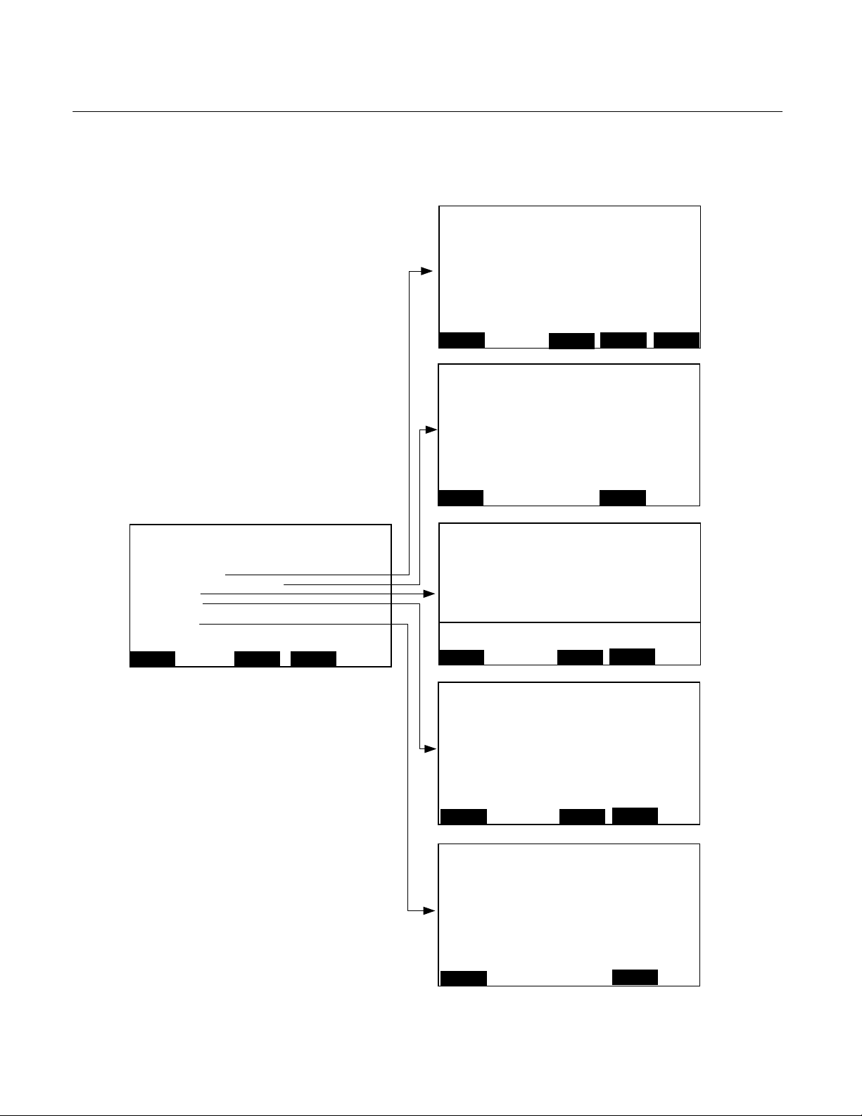
Instruction Manual
760002-A
July 2002
Model NGA2000 FID2
3-15 SYSTEM CONFIGURATION AND
DIAGNOSTICS
This menu and its submenus provides for
setup of the system parameters for the
FID2 77.25 ppm
-- System Configuration and Diagnostics --
System calibration…
Diagnostic menus…
Load/Save configuration (CMMCA)…
Date and time…
Security codes…
Network module management…
System reset…
Pump 1: Off
Pump2: Off
Measure
Channel
Back…
platform. The menu is accessed from the
Main Menu.
FID2 77.25 ppm
Control module diagnostics…
Analyzer module diagnostics…
Measure
FID2 77.25 ppm
Send configuration to serial interface!
Load configuration from serial interface!
Replace current configuration with factory settings!
Measure
FID2 77.25 ppm
Minutes: 0
Hours: 12
Year: 2001
Day: 1
Month: 7
Network updating: Enabled
Current time: 08:45.35 July 07, 2001
Measure
-- Diagnostic Menus --
Set !
Back…
Back…
Back…
<<<
-- Load/Save Configuration (CM/MCA) --
BE CAREFUL with this function –
-
-- Date and Time --
>>>
FID2 77.25 ppm
Basic level security: Disabled
Expert level security: Disabled
System level security: Disabled
Define basic level security PIN…
Define expert level security PIN…
Define system level security PIN…
Measure
FID2 77.25 ppm
System reset!
Measure
-- Security Codes --
Channel
-- System Reset --
Are you sure???
Back…
Back…
Figure 3-72. System Configuration and Diagnostics Menu - Sub Menus
3-48 Operation Rosemount Analytical Inc. A Division of Emerson Process Management
Page 81

Model NGA2000 FID2
The following is a short overview of the
contents of the menus:
System calibration…
1
Instruction Manual
760002-A
July 2002
a. Diagnostic Menus
This menu has two submenus for
viewing and resetting any software
errors.
Diagnostic menus…
Control module diagnostics…
1
Analyzer module diagnostics…
Software error messages
Loading/saving configuration
parameters…
Sending or loading of analyzer
configuration data by the serial interface
Date and time…
Date and time setup of the analyzer
Security codes…
Setup of security codes for the different
operating levels
Network module management…
1
System reset…
System reset and re-initializing of the
analyzer
Main Menu
↓
System configuration and
diagnostics…
↓
Diagnostic menus…
FID2 77.25 ppm
- Diagnostics Menus –
Control module diagnostics…
Analyzer module diagnostics…
Measure
<<< >>>
Back…
Figure 3-73. Diagnostics Menus
The “Control module diagnostics”
menu is not applicable to this analyzer
module.
1
Not used in this module. See NGA 2000 Platform
manual PN 760006
Rosemount Analytical Inc. A Division of Emerson Process Management Operation 3-49
Page 82

Instruction Manual
p
g
760002-A
July 2002
Model NGA2000 FID2
b. Analyzer Module Diagnostics
This menu provides access to several
submenus for viewing and adjusting
the various FID2 module parameters.
Main Menu
↓
System configuration and
diagnostics…
↓
Diagnostic menus…
↓
Analyzer module diagnostics…
FID2 77.25 ppm
Power supply voltages…
Primary variable parameters…
Physical measurements…
Temperature control parameters…
Miscellaneous control parameters…
Trend display control…
Auto ignition parameters…
Self test…
Software diagnostics…
Start u
analyzer…
HOME
- Analyzer Diagnostics –
ESCAPE INFO
Figure 3-74. Diagnostics Menus –
Analyzer Diagnostics Menu
Choose one of the submenus to view
or adjust the parameters.
Primary variable parameters…
Shows the value of internal parameters
used in the primary variable
calculation.
FID2 77.25 ppm
Raw measurement signal:
Raw measurement signal:
Preamp gain setting:
Preamp gain switch point:
Pk-pk noise:
Barometric pressure compensation:
Calibration factors…
HOME
- Primary Variable Parameters –
523988
0.005 V
260 ppm
0.00 ppm
Enabled
ESCAPE INFO
Low
Figure 3-76. Analyzer Diagnostics –
Primary Variable Parameters Menu
Barometric pressure compensation
may be enabled if another analyzer
has a pressure measurement device
and is set to report its reading.
For “Primary gain switch point:” see
Section 3-12c on page 3-39.
For “Calibration factors…” see Section
3-12b on page 3-38.
Power supply voltages…
The “is” lines show the current value of
the power supplies. The “was” values
show the values when the analyzer
was manufactured. Changes of more
than a few percent should be tracked.
FID2 77.25 ppm
+15V analog is:
+15V analog was:
-15V analog is:
-15V analog was:
+5V processor power is:
+5V processor power was:
+10V sensor power is:
+10V sensor power was:
Polarizing voltage is:
Polarizin
HOME
- Power Supply Voltages –
voltage was:
ESCAPE INFO
14.97 V
0.000 V
–14.83 V
0.0000 V
5.029 V
0.0000 V
9.980 V
0.0000 V
89.82 V
0.0000 V
Figure 3-75. Analyzer Diagnostics –
Power Supply Voltages Menu
3-50 Operation Rosemount Analytical Inc. A Division of Emerson Process Management
Page 83

Model NGA2000 FID2
p
Instruction Manual
760002-A
July 2002
Physical measurement…
These are measurements made by the
analyzer module to verify proper
functioning and appropriate flows of
sample and support gases, if any.
FID2 77.25 ppm
Sample capillary pressure:
Sample capillary pressure was:
Fuel supply pressure:
Fuel supply pressure was:
Burner air pressure:
Burner air pressure was:
Pressure limits…
Tem
HOME
- Physical Measurement Parameters –
erature limits…
ESCAPE INFOMORE
38.6 hPa
0.0 hPa
68.0 hPa
0.0 hPa
124.1 hPa
0.0 hPa
Figure 3-77. Analyzer Diagnostics –
Physical Measurement Parameters
Menu (Screen 1 of 2)
Press the MORE (F3) key for
additional parameters.
FID2 77.25 ppm
Block temperature:
Block temperature was:
Flame temperature:
Flame temperature was:
Preamplifier temperature:
Preamplifier temperature was:
- Physical Measurement Parameters –
39.2 C
0.0 C
140.0 C
0.0 C
29.0 C
0.0 C
Pressure limits…
Used to set Warning alarms for the
three internal pressure functions.
FID2 77.25 ppm
Sample capillary upper limit:
Sample capillary lower limit:
Fuel pressure upper limit:
Fuel pressure lower limit:
Burner air upper limit:
Burner air lower limit:
HOME
- Pressure Limits –
500 hPa
100 hPa
1500 hPa
400 hPa
1500 hPa
200 hPa
ESCAPE INFO
Figure 3-79. Analyzer Diagnostics –
Pressure Limits Menu
Temperature limits…
Used to set Warning alarms for the
three internal temperature functions.
FID2 77.25 ppm
Block upper limit:
Block lower limit:
Flame upper limit:
Flame lower limit:
Preamp upper limit:
Preamp lower limit:
HOME
- Temperature Limits –
150 C
40.0 C
280 C
100 C
50.0 C
30.0 C
ESCAPE INFO
HOME
ESCAPE INFO
Figure 3-80. Analyzer Diagnostics –
Temperature Limits Menu
Figure 3-78. Analyzer Diagnostics –
Physical Measurement Parameters
Menu (Screen 2 of 2)
See Section 3-8i, Physical
Measurements and Pressure Limits on
page 3-29 for a complete description.
Rosemount Analytical Inc. A Division of Emerson Process Management Operation 3-51
Page 84

Instruction Manual
760002-A
July 2002
Model NGA2000 FID2
Temperature control parameters…
Displays the parameters used by the
temperature control PID algorithms.
FID2 77.25 ppm
Block set point:
Block P gain:
Block I gain:
Block bias:
Block temperature:
Controller duty cycle:
Block temperature heater control:
HOME
- Temperature Control –
80.0 C
0.1000000
0.0001000
43.0 C
ESCAPE INFO
99%
Figure 3-81. Analyzer Diagnostics –
Temperature Control Parameters
Menu
The Block heater control can be turned
ON or OFF. This should only be
changed under the direction of
Rosemount technical support.
Miscellaneous control parameters…
Block heater current shows the actual
current flow to the block heater.
0.5
ON
SETTING EXCEPT UNDER
DIRECTION FROM ROSEMOUNT
ANALYTICAL.
Pressure settings…
Used to set the internal pressures for
fuel and burner air. Displays the
current pressures and those
established at manufacturing. See
Section 3-3b on page 3-10 for the
relationships between the various
pressures and the primary variable
response.
FID2 77.25 ppm
Fuel supply pressure setting:
Fuel supply pressure:
Fuel supply pressure was:
Burner air pressure setting:
Burner air pressure:
Burner air pressure was:
Fuel ignition pressure setting:
Burner air ignition pressure setting:
Pressure limits…
HOME
- Pressure Settings –
ESCAPE INFOBACK
550.00 hPa
0.0 hPa
1200.0 hPa
0.0 hPa
650 hPa
220.00 hPa
Figure 3-83. Miscellaneous Control
Parameters – Pressure Settings
Menu
hPa
hPa
FID2 77.25 ppm
Air flow control signal:
Fuel flow control signal:
Pressure settings…
HOME
- Miscellaneous Control Parameters –
ESCAPE INFOBACK
0.000 V
0.000 V
Figure 3-82. Analyzer Diagnostics –
Miscellaneous Control Parameters
Menu
Manual ignition and fuel enrichment
are controlled by the switch on the
front panel of the module.
“Alarm messages valid for” sets the
condition under which alarms occur:
FAILURE, SAFETY FAILURE, ANY,
OR WARNING.
Fuel type can be set for H2-He, H2-N2,
and H2. DO NOT CHANGE THIS
Fuel ignition pressure and burner air
ignition pressure should only be
changed under direction from
Rosemount.
Pressure limits are described on the
previous page.
3-52 Operation Rosemount Analytical Inc. A Division of Emerson Process Management
Page 85

Model NGA2000 FID2
Instruction Manual
760002-A
July 2002
Trend display control…
The FID2 analyzer module stores a
rolling 24 hours of 15-minute averages.
These values are only accessible
using a computer and the SIO. Use
variables DATA_INDEX and
DATA_POINT to access them.
FID2 77.25 ppm
First displayed variable:
Second displayed variable:
Timebase:
Drop out to measure mode:
HOME
- Trend Display Control –
Concentration
Sample flow
24 Hrs
DISABLED
ESCAPE INFO
Figure 3-84. Analyzer Diagnostics –
Trend Display Control Menu
Choose the displayed variables from:
Concentration
Sample flow
Block temperature
Flame temperature
Preamp temperature
Sample pressure
Burner air pressure
Fuel pressure
Noise level
Raw signal
Auto fuel override is the time that the
fuel flow is changed for ignition in the
range of 5 to 45 seconds.
Auto ignite override is the time allowed
for ignition in the range of 2 to 30
seconds.
Auto ignition number of cycles is the
number of attempts for ignition in the
range of 1 to 5.
Do not attempt to change these
variables without instructions from
Rosemount
Self test results…
Used to view the results of the last self
test for RAM and power supply or to
initiate a new self test.
FID2 77.25 ppm
RAM test:
Power supply test:
HOME
- Self Test Results –
ESCAPE INFOTEST
Pass
Pass
Figure 3-86. Analyzer Diagnostics –
Self Test Results Menu
Auto ignition parameters…
Used to set the parameters for auto
ignition.
FID2 77.25 ppm
Auto fuel override duration:
Auto ignite override duration:
Auto ignition number of cycles:
Auto ignition:
Fuel enrichment status:
Flame status:
HOME
- Auto Ignition Parameters –
ENABLED
OFF
ESCAPE INFO
30 s
10 s
ON
3
Press the F3 (TEST) button to initiate a
self test.
Figure 3-85. Analyzer Diagnostics –
Auto Ignition Parameters Menu
Rosemount Analytical Inc. A Division of Emerson Process Management Operation 3-53
Page 86

Instruction Manual
(
p
760002-A
July 2002
Model NGA2000 FID2
Software diagnostics…
Shows any software errors since last
reset. The FID2 analyzer module has
extensive error recovery code. Errors
may correct themselves or mean
nothing. Report any errors to
Rosemount service, noting the error
code in the last line.
FID2 77.25 ppm
Last message:
And:
And:
And:
And:
And:
And:
And:
Edit to reset:
Software error code
HOME
- Software Diagnostics –
1 = no error):
ESCAPE INFO
Report
Figure 3-87. Analyzer Diagnostics –
Software Diagnostics Menu
Change the “Edit to reset” line from
Report to Reset to rest any errors.
Start up analyzer…
Displays various parameters during
analyzer startup. The analyzer
performs a self test routine and waits
in the standby mode until the flame is
lit and the block temperature has
stabilized.
FID2 77.25 ppm
Time on this cycle:
Block temperature:
Sample pressure:
Burner air pressure:
Fuel pressure:
Fuel flow status:
Fuel enrichment status:
Igniter status…
Flame condition:
Flame tem
1
HOME
- Analyzer Starting Up –
124.11 hPa
erature:
LIGHT INFO
REBOOT
INIT
69.5 C
38.61 hPa
68.95 hPa
ON
OFF
OFF
ON
180.0 C
0
Figure 3-88. Analyzer Diagnostics –
Analyzer Starting Up Menu
LIGHT (F2) – performs an auto ignite
routine.
REBOOT (F3) - restarts the analyzer
INIT (F4) - erases all but
manufacturing data from the
configuration memory.
3-54 Operation Rosemount Analytical Inc. A Division of Emerson Process Management
Page 87

Model NGA2000 FID2
c. Load/Save Module Configuration
This menu provides several functions
to send or load configuration data of
the analyzer through the serial
interface. These functions are only
available if an SIO with serial interface
is installed.
NOTE
When loading configuration data all
of the current configuration in the
memory will be overwritten.
Main Menu
↓
System configuration and
diagnostics…
↓
Load/save configuration
(CM/MCA)…
Instruction Manual
760002-A
July 2002
Send configuration to serial
interface !
The configuration data in memory will
be sent through the serial interface of
the analyzer to an external computer
or other device.
Load configuration data from serial
interface !
Configuration data will be loaded into
memory from an external computer or
other device through the serial
interface of the analyzer. The current
configuration in memory will be
overwritten.
Replace current configuration with
factory settings !
Deletes the configuration in memory
and re-establishes the factory default
setting from the Flash-EPROM.
FID2 77.25 ppm
- Load/Save Configuration (CM/MCA) –
Send configuration to serial interface!
Load configuration from serial interface!
BE CAREFUL with this function –
-
Replace current configuration with factory settings!
Measure
Back…
Figure 3-89. System Configuration
and Diagnostics - Load/Save
Configuration (CM/MCA) Menu
Select a line with the ↑ or ↓ keys.
Press the ↵ or → keys to start the
function.
If asked, confirm with the F2 (Yes) key
or cancel and go back to the menu
page with the F4 (Back…) or ← key.
Rosemount Analytical Inc. A Division of Emerson Process Management Operation 3-55
Page 88

Instruction Manual
760002-A
July 2002
d. Date and Time
Model NGA2000 FID2
This menu is used to set the date, time
and format for the analyzer.
Main Menu
↓
System configuration and
diagnostics…
↓
Date and time…
FID2 77.25 ppm
- Date and Time -
Minutes:
Hours:
Year:
Day:
Month:
Network updating:
Current time:
Measure
Set !
08:45:35 July 07, 2002
Back…
2002
Enabled
Figure 3-90. System Configuration
and Diagnostics - Date and Time
Menu
Select a line with the ↑ or ↓ keys.
Press the ↵ or → keys to select the
parameter.
Select any digit with the ← or → key
and set a new value with the ↑ or ↓
key.
Network updating:
Not used with this model.
0
12
1
7
Set up a new date or time:
Set the “Minutes,” “Hours,” “Year,”
“Day,” or “Month” lines and make any
desired adjustments. Press the F3
(Set!) key to set the new time and
date. The “Current time” line will
change to reflect the new time and
date set.
3-56 Operation Rosemount Analytical Inc. A Division of Emerson Process Management
Page 89

Model NGA2000 FID2
y
Instruction Manual
760002-A
July 2002
e. Security Codes
This menu is used to set the security
codes for the three levels of security.
CAUTION
If a security code is lost or forgotten,
there is no possibility of entering the
locked security level.
Main Menu
↓
System configuration and
diagnostics…
↓
Security codes…
FID2 77.25 ppm
- Security Codes -
Basis level security:
Expert level security:
System level security:
Define basic level security PIN…
Define expert level security PIN…
stem level security PIN…
Define s
Measure
Channel
Back…
Figure 3-91. System Configuration
and Diagnostics - Security Codes
Menu
Use the function keys F1 to F5 to enter
the numerical security code in the
desired sequence. The numbers will
appear in the “Actual PIN” line as they
are entered. The characters displayed
on the function keys cannot be entered
as code numbers.
Example:
FID2 77.25 ppm
- Define Basic Level Security PIN -
Press five softkeys in any order to define the PIN.
The actual PIN is represented by the order in which they are
pressed, and shown numerically below.
Press the left arrow key when you are done.
Disabled
Disabled
Disabled
Press the ← key to return to the
Security setup” menu.
Enable the security code
Select the desired security level line to
enable. Change the parameter to
“Enabled.”
CAUTION
If System level is enabled, it will not be
possible to re-enter the Security Setup
and change back to Disabled without
the code.
Entering a level locked by security
code
For example, return to the Main Menu
by pressing the F4 key twice.
Attempt to enter an enabled level by
choosing the menu line. A new menu
will appear requesting entry of the
security code. Enter the correct code
using the correct sequence of function
keys. The asterisk (*) symbol will
appear for each entry.
If the code is incorrect, the message
“Ready” will appear in the line and
access to the locked level is
prevented. If the code is correct, the
display will change to the locked level
after the last digit of the correct code is
entered.
NOTE
Once a locked security level has
been entered, it will remain unlocked even after exiting to a different security level. To protect the
level, press the F4 (Lock..) key in
the Main Menu after returning from
the locked level.
Actual PIN:
ABCDE1
Rosemount Analytical Inc. A Division of Emerson Process Management Operation 3-57
FGHIJ2
KLMNO3
PQRST4
12345
UVWXYZ5
Page 90

Instruction Manual
760002-A
July 2002
f. System Reset
Model NGA2000 FID2
Resets the analyzer to the initializing
mode which is the same as switching
the power off and then on.
Main Menu
↓
System configuration and
diagnostics…
↓
System reset…
FID2 77.25 ppm
- System Reset -
Are you sure ???
System reset !
Measure
Back…
Figure 3-92. System Configuration
and Diagnostics - System Reset
Menu
g. System Tag
Used to change the system tag from
the default to any desired literal.
In the System Configuration and
Diagnostics Menu (Figure 3-72 on
page 3-48) go to the System tag… line
and press the enter key.
Main Menu
↓
System configuration and
diagnostics…
↓
System tag…
3-58 Operation Rosemount Analytical Inc. A Division of Emerson Process Management
Page 91

Model NGA2000 FID2
MAINTENANCE AND SERVICE
Instruction Manual
760002-A
July 2002
SECTION 4
WARNING
PARTS INTEGRITY
Tampering with or unauthorized substitution of components may adversely affect
safety of this product. Use only factoryapproved components for repair.
WARNING
ELECTRICAL SHOCK HAZARD
Disconnect power to the module(s) prior to
replacing components.
CAUTION
QUALIFIED PERSONNEL
This equipment should not be adjusted or
repaired by anyone except properly qualified service personnel.
The FID2 Analyzer Module requires very little
maintenance during normal operation.
4-1 OVERVIEW
The FID2 Analyzer Module requires very little
maintenance during normal operation.
Service is usually limited to fuse replacement
and burner repair or replacement.
Preventative maintenance is limited to
checking and possible replacement of the
exhaust tubing.
Refer to Figure 1-2. FID2 Analyzer Flow
Diagram on page 1-3 and Figure 1-3. FID2
Wiring Diagram on page 1-4.
REAR
Flow Control Manifold
Burner Block
Regulator
Oven
(Cover removed)
Figure 4-1. Location of Major Components
Intrinsic Safety Board
Computer Board
FRONT
Module Board
Rosemount Analytical Inc. A Division of Emerson Process Management Maintenance and Service 4-1
Page 92

Instruction Manual
760002-A
July 2002
Model NGA2000 FID2
4-2 DISASSEMBLY
Refer to Figure 4-2. Removal of FID2 Cover
below and Figure 4-5. FID2 – Exploded
View on page 4-5 for illustrations of
disassembly.
4-3 FUSES
The analyzer module has five fuses, all of
which are located on the Module Board.
The main power fuse is accessible through
the front panel of the instrument. See Figure
4-3. Main Power Fuse Location on page 4-3.
The remaining fuses are located on the solder
side of the Module Board (the side facing
downward). To access these four fuses, the
Module Board must be removed from the
analyzer (see Figure 4-4. Fuse Locations on
Module Board on page 4-3).
NOTE
Before replacing the fuses, remove power
to the Analyzer Module.
Figure 4-2. Removal of FID2 Cover
4-2 Maintenance and Service Rosemount Analytical Inc. A Division of Emerson Process Management
Page 93

Model NGA2000 FID2
FUEL OVERRIDE
IGNITE
POWER FLAME BLOC K SAMPLE IG NITE FUEL/A IR
OK
Figure 4-3. Main Power Fuse Location
Fuse
3 2 1 LON2 LON1
T 6A
24V
250 V
Instruction Manual
760002-A
July 2002
FID 2
R32
F3
F5
F4
F2
Figure 4-4. Fuse Locations on Module Board
Rosemount Analytical Inc. A Division of Emerson Process Management Maintenance and Service 4-3
Page 94

Instruction Manual
760002-A
July 2002
Model NGA2000 FID2
4-4 BURNER BLOCK REMOVAL AND
INSTALLATION
CAUTION
QUALIFIED PERSONNEL
The burner block assembly should not be
adjusted, cleaned or repaired by anyone
except factory service personnel. Failure
to observe this caution will void agency
approvals.
CAUTION
BURNER
If a burner problem occurs, remove the
burner block assembly from the oven and
return it to Rosemount Analytical for maintenance and/or repair (see return of material on page 6-1).
The block is temperature controlled at
70°C. Allow unit to cool before touching
any of these components.
Removal
Refer to Figures 4-1, 4-2, 4-6, 4-7 and 4-8.
1. Power OFF the module
2. Shut off gas, air and sample gases.
3. Refer to Figure 4-2 on page 4-2. Remove
the 24 screws securing the module cover.
Remove the cover.
4. Refer to Figure 4-6 on page 4-6. Remove
the four screws securing the oven cover.
Remove the oven cover.
6. Disconnect the Air, Fuel and Sample
Capillaries.
7. Disconnect the exhaust tube at the oven
wall outlet.
8. Loosen the four hex nuts holding the
burner block assembly in the oven. Slide
the block towards the rear of the module
and lift out.
Installation is the reverse of removal.
4-5 BURNER STARTUP AND
TROUBLESHOOTING
If burner startup is not achievable, check the
following:
1. All supply gas cylinder pressures are
within specification (see Specifications in
Preface).
2. Correct gases are being supplied to each
back panel inlet.
3. Air, not zero gas (if nitrogen), is being
supplied to burner.
4. Burner exhaust is being vented to
atmospheric pressure, and is not tied to
either purge air exhaust or another FID
exhaust.
5. Burner exhaust continuously slopes
downward until reaching atmospheric
pressure vent.
6. IS parameters match WAS parameters in
the Physical Measurement screen (Figure
3-77 and Figure 3-78 on page 3-51); use
MORE softkey to view all parameters.
5. Refer to Figure 4-7 on page 4-7, and
Figure 4-8 on page 4-8. Disconnect the
RTD Cable, 90V Cable, Thermistor Cable,
Signal Cable and Ignitor Cable.
4-4 Maintenance and Service Rosemount Analytical Inc. A Division of Emerson Process Management
Page 95

Model NGA2000 FID2
g
Front Panel
Instruction Manual
760002-A
July 2002
Computer Board
Module Board
Block Heater
Burner Block
Mounting Bracket,
Re
ulator
Regulator
Tube, Sample In
Tube, Sample
Bypass Out
Tube,
Exhaust
Burner
Exhaust
Out
Sample
Bypass
Out
Sample In
Flow Control
Manifold
Figure 4-5. FID2 – Exploded View
Rosemount Analytical Inc. A Division of Emerson Process Management Maintenance and Service 4-5
Page 96

Instruction Manual
760002-A
July 2002
Front Panel
Module
Board
Model NGA2000 FID2
Oven Cover
Computer
Board
Intrinsic Safety
Board
Regulator
Burner Block
Rear Panel
Flow Control
Manifold
Figure 4-6. Removal of Oven Cover
4-6 Maintenance and Service Rosemount Analytical Inc. A Division of Emerson Process Management
Page 97

Model NGA2000 FID2
RTD
RTD Cable
Instruction Manual
760002-A
July 2002
Cover
90V Cable
Signal Cable
Burner
(see Figure 4-8)
Cover Plate
Heater
Base
Mounting Plate
NOTE
This exploded view of the burner block is for information only. All servicing of the burner block
must be performed by Rosemount Analytical.
Figure 4-7. Burner Block -Exploded View
Rosemount Analytical Inc. A Division of Emerson Process Management Maintenance and Service 4-7
Page 98

Instruction Manual
760002-A
July 2002
Exhaust
Ignitor Cable
(green)
90V Cable
(coax)
Model NGA2000 FID2
Thermistor Cable
(yellow)
Sample Capillary
Air Capillary
Fuel Capillary
NOTE
This view of the burner is for information only. All servicing of the burner must be performed by
Rosemount Analytical.
Figure 4-8. Burner
4-6 MAINTENANCE SCHEDULE
ITEM EVENT TIME
Replace Exhaust Tubing If plastic cracked Approx. 5 years
4-8 Maintenance and Service Rosemount Analytical Inc. A Division of Emerson Process Management
Page 99

Instruction Manual
760002-A
Model NGA2000 FID2
July 2002
SECTION 5
REPLACEMENT PARTS
WARNING
PARTS INTEGRITY
Tampering with or unauthorized substitution of components may adversely affect safety of this product.
Use only factory-approved components for repair.
5-1 MATRIX
To identify the configuration of an analyzer,
Each analyzer is configured per the customer
sales order. Below is the FID2 sales matrix
which lists the various configurations
available.
FIDII NGA 2000 HYDROCARBON ANALYZER - FIDII (ANALYZER MODULE)
Code Software Version
01 Current Software
02 2.5 Version Software
03 3X Version Software - specify version
locate the analyzer name-rating plate. The
sales matrix identifier number appears on the
analyzer name-rating plate.
Code Configurations, Mixed Fuel, Std Input Pressures, 5#Reg
A1 0-10 to 0-5000 ppm CH4: Inlet Pressure 12.5 PSI, Restrictor 7.5#
A2 0-10 to 0-5000 ppm CH4: Inlet Pressure 7 PSI, Restrictor 5#
A3 0-10 to 0-5000 ppm CH4: Inlet Pressure 5 PSI, No Restrictor
A4 0-100 to 0-5000 ppm CH4: Inlet Pressure 12.5 PSI, Restrictor 7.5#
A5 0-100 to 0-5000 ppm CH4: Inlet Pressure 7 PSI, Restrictor 5#
A6 0-100 to 0-5000 ppm CH4: Inlet Pressure 5 PSI, No Restrictor
A7 0-100 to 0-10000 ppm CH4: Inlet Pressure 12.5 PSI, Restrictor 7.5#
A8 0-100 to 0-10000 ppm CH4: Inlet Pressure 7 PSI, Restrictor 5#
A9 0-100 to 0-10000 ppm CH4: Inlet Pressure 5 PSI, No Restrictor
Configurations, Mixed Fuel, Low Input Pressures, 2# Reg
G1 0-10 to 0-5000 ppm CH4: Inlet Pressure 2 PSI, No Restrictor
G2 0-100 to 0-5000 ppm CH4: Inlet Pressure 2 PSI, No Restrictor
G3 0-100 to 0-10000 ppm CH4: Inlet Pressure 2 PSI, No Restrictor
99 Special Factory Calibrated Ranges
Code Special Requirements
00 None
G1 Customer Option
99 Special
FIDII 01 A1 00 Example
Rosemount Analytical Inc. A Division of Emerson Process Management Replacement Parts 5-1
Page 100

Instruction Manual
760002-A
July 2002
5-2 REPLACEMENT PARTS
658350 Board Assembly, Computer
659060 Board Assembly, Module
659070 Board Assembly, Intrinsically safe
903347 Fuse, 6A (Main Power)
903823 Fuse, 4A (F2, F3 on Module Board)
903824 Fuse, 5A (F4, F5 on Module Board)
659063 Regulator
659225 Burner/Block Assembly
658144 Heater, Block
659043 Flow Control Manifold Assembly
The following components are selectable per
application. Consult factory.
Fuel Capillary
Restrictor, Flow
Sample Capillary
Model NGA2000 FID2
5-2 Replacement Parts Rosemount Analytical Inc. A Division of Emerson Process Management
 Loading...