

Page 1

NGA 2000
LAME IONIZATION
F
NALYZER
A
ETECTOR
D
ODULE
M
Rosemount Analytical
2
Page 2

N
OTICE
T
HE INFORMATION CONTAINE D IN THIS DOCUMENT IS SUBJ E CT T O CHANGE WITHOUT NOTICE
.
Rosemount Analytical's NGA 2000 system of Modular G as Analyzers and Controllers are patented,
under U.S. Patent 5.787.015.
Manual Part Number 748364-D
November 1998
Printed in U.S.A.
Rosemount Analytical Inc.
4125 East La Palma Avenue
Anaheim, California 92807-1802
Page 3

ONTENTS
C
PREFACE
PURPOSE/SAFETY SUMMARY........................................................................P-1
GLOSSARY ......................................................................................................P-4
SPECIFICATIONS - GENERAL .........................................................................P-7
SPECIFICATIONS – GAS REQUIREMENTS .................................................... P-8
SPECIFICATIONS - PHYSICAL.........................................................................P-9
SPECIFICATIONS - GAS CONNECTIONS .......................................................P-9
CUSTOMER SERVICE, TECHNICAL ASSISTANCE AND FIELD SERVICE....P-10
RETURNING PARTS TO THE FACTORY.........................................................P-10
TRAINING ......................................................................................................P-10
DOCUMENTATION............................................................................................P-10
COMPLIANCES .................................................................................................P-11
QUICK STARTUP PROCEDURE.......................................................................P-13
SECTION 1. INTRODUCTION
1.1 OVERVIEW..............................................................................................1-1
1.2 TYPICAL APPLICATIONS .......................................................................1-2
1.3 THEORY OF TECHNOLOGY...................................................................1-2
1.4 GAS SAFETY FEATURES.......................................................................1-3
1.5 FUEL GAS OPTION.................................................................................1-4
S
ECTION
2.1 UNPACKING............................................................................................2-1
2.2 ASSEMBLY..............................................................................................2-1
2.3 LOCATION...............................................................................................2-1
2.4 GASES.....................................................................................................2-2
2. I
2.4.1 Connections................................................................................2-3
NSTALLATION
748364-D Rosemount Analytical November 1998
NGA 2000 FID 2 Analyzer Module
i
Page 4

C
ONTENTS
SECTION 2. (CONTINUED)
2.4.2 Gas Specifications...................................................................... 2-3
2.5 ELECTRICAL CONNECTIONS ............................................................... 2-5
2.6 INSTALLATION GUIDELINES................................................................. 2-7
SECTION 3. STARTUP AND OPERATION
3.1 OVERVIEW ............................................................................................. 3-1
3.2 DISPLAYS ............................................................................................... 3-1
3.2.1 Run Mode Display...................................................................... 3-1
3.2.2 Menu Displays............................................................................ 3-2
3.2.3 Help Displays ............................................................................. 3-4
3.3 STARTUP PROCEDURE ........................................................................ 3-4
3.4 OPTIMIZATION PROCEDURE................................................................ 3-9
3.5 BINDING.................................................................................................. 3-9
3.6 CALIBRATION......................................................................................... 3-10
3.7 CALIBRATION DETAILS......................................................................... 3-12
3.8 ROUTINE OPERATION........................................................................... 3-13
3.9 SHUT DOWN PROCEDURE..................................................................... 3-14
3.10 SAFETY SYSTEM................................................................................... 3-14
3.11 ALARM INDICATIONS............................................................................. 3-14
3.12 CONFIGURATION STORAGE ................................................................ 3-15
SECTION 4. MAINTENANCE AND TROUBLESHOOTING
4.1 GENERAL................................................................................................ 4-1
4.2 FUSES..................................................................................................... 4-2
4.3 BURNER BLOCK REMOVAL AND INSTALLATION............................... 4-3
4.4 BURNER STARTUP TROUBLESHOOTING........................................... 4-4
4.5 MAINTENANCE SCHEDULE .................................................................. 4-7
S
ECTION
5.
REPLACEMENT PARTS
5.1 REPLACEMENT PARTS......................................................................... 5-1
ii
November 1998 Rosemount Analytical 748364-DNGA 2000 FID 2 Analyzer Module
Page 5

APPENDIX A. GAS SAFETY FEATURES
A.1 GAS SAFETY FEATURES.......................................................................A-1
A.2 FUEL GAS OPTION.................................................................................A-1
C
ONTENTS
A
PPENDIX
B.1 ANALYZER SETUP CHECKLIST............................................................B-1
B.2 AUXILIARY MODULE SETUP.................................................................B-3
B.3 COMPUTER INTERFACE SETUP ..........................................................B-3
B. A
B.1.1 System Setup.............................................................................B-1
B.1.2 Analyzer Module Setup..............................................................B-1
NALYZER SETUP CHECKLIST
APPENDIX C. USER INTERFACE HELP
C.1 INSTRUCTIONS......................................................................................C-1
C.2 MENU ITEMS ..........................................................................................C-1
APPENDIX D. FID 2 MENU STRUCTURE
D.1 BASIC CONTROLS MENUS ...................................................................D-1
D.2 EXPERT CONTROLS MENUS................................................................D-3
D.3 ANALYZER SETUP MENUS...................................................................D-6
D.4 ANALYZER TECHNICAL CONFIGURATION MENUS............................D-15
D.5 DIAGNOSTIC MENUS.............................................................................D-19
APPENDIX E. FID 2 IDENTIFICATION MATRIX
ENERAL PRECAUTIONS FOR HANDLING AND STORING HIGH PRESSURE CYLINDERS
G
ARRANTY
W
IELD SERVICE AND REPAIR FACILITIES
F
748364-D Rosemount Analytical November 1998
NGA 2000 FID 2 Analyzer Module
iii
Page 6

C
ONTENTS
FIGURES
P-1 FID 2 Front Panel.................................................................................... P-13
1-1 FID 2 Analyzer Module............................................................................ 1-1
1-2 Flame Ionization Detection Technology................................................... 1-2
1-3 FID 2 Analyzer Flow Diagram.................................................................. 1-3
2-1 FID 2 Outline and Mounting Dimensions................................................. 2-3
2-2 FID 2 Rear Panel..................................................................................... 2-4
2-3 FID 2 Front Panel .................................................................................... 2-6
3-1 Run Mode Display....................................................................................3-1
3-2 Main Menu............................................................................................... 3-2
3-3 Basic Controls Menu................................................................................ 3-3
3-4 Expert Controls Menu.............................................................................. 3-3
3-5 Analyzer Module Setup Menu.................................................................. 3-4
3-6 Typical Help Menu................................................................................... 3-4
3-7 Analyzer Diagnostics Menu ..................................................................... 3-5
3-8 Self Test Results Menu............................................................................ 3-5
3-9 Light Flame Menu.................................................................................... 3-6
3-10 Typical Curves of Module Response vs. Pressure Setting on
Sample Pressure Regulator.......................................................... 3-7
3-11 Typical Curves of Module Response vs. Pressure Setting on
Fuel Pressure Regulator............................................................... 3-8
3-12 Typical Curves of Module Response vs. Pressure Setting on
Air Pressure Regulator................................................................. 3-8
3-13 Typical Calibration Gas List Menu........................................................... 3-10
3-14 Zero and Span Calibration Menu............................................................. 3-10
3-15 Calibration Parameters Menu.................................................................. 3-10
3-16 Zero/Span Diagnostic Data (Span).......................................................... 3-11
3-17 Analyzer Manufacturing Data Menu......................................................... 3-13
3-18 Store/Restore User Settings Menu.......................................................... 3-16
3-19 Store Historical Data Menu...................................................................... 3-16
4-1 Locations of Major Components of the FID 2.......................................... 4-1
4-2 Removal of FID 2 Cover .......................................................................... 4-2
4-3 Main Power Fuse..................................................................................... 4-2
4-4 Fuse Locations on Module Board............................................................ 4-3
4-5 Physical Measurement Parameters Menu............................................... 4-4
4-6 FID 2 – Exploded View............................................................................ 4-5
4-7 Burner Block – Exploded View.................................................................4-6
4-8 Burner...................................................................................................... 4-7
iv
November 1998 Rosemount Analytical 748364-DNGA 2000 FID 2 Analyzer Module
Page 7

FIGURES (CONTINUED)
D-1 Main Menu...............................................................................................D-1
D-2 Basic Control Menu..................................................................................D-1
D-3 Zero “Are you sure?” Menu......................................................................D-2
D-4 Light Flame Menu....................................................................................D-2
D-5 Main Menu...............................................................................................D-3
D-6 Expert Controls and Setup Menu.............................................................D-3
D-7 Expert Controls Menu..............................................................................D-4
D-8 Range Settings Menu..............................................................................D-4
D-9 Zero/span Calibration Menu - Zero..........................................................D-5
D-10 Analyzer Zero Menu.................................................................................D-5
D-11 Zero/Span Diagnostic Data Menu............................................................D-6
D-12 Analyzer Module Set Up Menu ................................................................D-6
D-13 Calibration Gas List Menu........................................................................D-7
D-14 Calibration Parameters Menu..................................................................D-7
D-15 Gas Measurement Parameters Menu......................................................D-8
D-16 Linearization Parameters.........................................................................D-9
D-17 Linearity Coefficients Menu......................................................................D-9
D-18 Response Time/Delay Parameters Menu................................................D-10
D-19 Units Menu...............................................................................................D-11
D-20 Midpoint Correction Set Up Menu............................................................D-12
D-21 Physical Measurements Parameters Menu.............................................D-12
D-22 Physical Measurements Parameters (More) Menu .................................D-13
D-23 Pressure Limits Menu..............................................................................D-13
D-24 Temperature Limits Menu........................................................................D-14
D-25 Displayed Parameters Menu....................................................................D-14
D-26 Store/Restore User Settings Menu..........................................................D-15
D-27 Main Menu..............................................................................................D-15
D-28 Technical Configuration Menu.................................................................D-16
D-29 Control Module Service Menu..................................................................D-16
D-30 Control Module Manufacturing Data Selection Menu ..............................D-16
D-31 Analyzer Manufacturing Data ..................................................................D-17
D-32 Control Module Service History Selection Menu......................................D-17
D-33 Analyzer Service History Menu...............................................................D-18
D-34 Analyzer Module Service Notes...............................................................D-18
D-35 Control Module Diagnostic Selection Menu.............................................D-19
D-36 Analyzer Diagnostics Menu .....................................................................D-19
D-37 Power Supply Voltages Menu..................................................................D-20
D-38 Primary Variable Parameters Menu.........................................................D-20
D-39 Calibration Factors Selection Menu.........................................................D-21
C
ONTENTS
748364-D Rosemount Analytical November 1998
NGA 2000 FID 2 Analyzer Module
v
Page 8

C
ONTENTS
FIGURES (CONTINUED)
D-40 Range 1 Factors Menu............................................................................ D-21
D-41 Range 1 Factors History Menu................................................................ D-22
D-42 Physical Measurements Parameters Menu............................................. D-22
D-43 Temperature Control Parameters Menu.................................................. D-23
D-44 Miscellaneous Control Parameters Menu ............................................... D-23
D-45 Miscellaneous Control parameters (more) Menu .................................... D-24
D-46 Pressure Settings Menu.......................................................................... D-24
D-47 Trend Storage Control............................................................................. D-25
D-48 Auto Ignition Parameters Menu............................................................... D-25
D-49 Self Test Results..................................................................................... D-26
D-50 Software Diagnostics............................................................................... D-26
D-51 Analyzer Starting Up Menu .................................................................... D-27
D-52 Re-Initialize Menu................................................................................... D-27
TABLES
1-1 Gas Flow Rates....................................................................................... 1-5
1-2 Analyzer Characteristics Relative to Fuel Gas......................................... 1-5
2-1 Gas Supply Pressures............................................................................. 2-5
3-1 FID 2 Analyzer Module Alarms ................................................................ 3-15
4-1 Maintenance Schedule............................................................................ 4-7
A-1 Typical Flow Rates with Premixed Fuel................................................... A-2
A-2 Analyzer Characteristics for Different Fuels............................................ A-3
vi
November 1998 Rosemount Analytical 748364-DNGA 2000 FID 2 Analyzer Module
Page 9

P
REFACE
PURPOSE/SAFETY SUMMARY
The purpose of this manual is to provide information concerning the components,
functions, installation and maintenance of this particular NGA 2000 module.
Some sections may describe equipment not used in your configuration. The user
should become thoroughly familiar with the operation of this module before operating
it. Read this instruction manual completely.
To avoid explosion, loss of life, personal injury and damage to this equipment
and on-site property, all personnel authorized to install, operate and service this
equipment should be thoroughly familiar with and strictly follow the instructions
in this manual. Save these instructions.
If this equipment is used in a manner not specified in these instructions,
protective systems may be impaired.
DANGER is used to indicate the presence of a hazard which will cause severe
personal injury, death, or substantial property damage if the warning is ignored.
WARNING is used to indicate the presence of a hazard which can cause severe
personal injury, death, or substantial property damage if the warning is ignored.
CAUTION is used to indicate the presence of a hazard which will or can cause minor
personal injury or property damage if the warning is ignored.
NOTE is used to indicate installation, operation or maintenance information which is
important but not hazard-related.
WARNING: ELECTRICAL SHOCK HAZARD
Operate this equipment only when covers are secured. Servicing requires
access to live parts which can cause death or serious injury. Refer servicing to
qualified personnel.
For safety and proper performance, this module must be connected to a
properly grounded three-wire source of electrical power.
748364-D Rosemount Analytical November 1998
NGA 2000 FID 2 Analyzer Module
P-1
Page 10
REFACE
P
WARNING: POSSIBLE EXPLOSION HAZARD
This equipment is used in the analysis of sample gases which may be
flammable, and the burner fuel used in the ionization process IS flammable. A
system of intrinsically safe electronics and an explosion proof tower are used to
prevent any ignition of a flammable gas leak. For this to be effective, the
module MUST be placed in a well-ventilated area, with unobstructed air flow
around it.
DO NOT place it within another enclosure without assuring this ventilation.
DO NOT obstruct the vent holes on the top and sides of the module.
DO NOT place the FID module within another enclosure unless the latter has a
guaranteed air circulation such as to dilute a worst case fuel or sample leak
below 25% of the LEL. Doing so will negate the safety features and may result
in an explosion, serious injury, property damage and death.
WARNING: FLAMMABLE SAMPLES
Consult the factory if flammable samples will be measured.
WARNING: PARTS INTEGRITY
Tampering with or unauthorized substitution of components may adversely
affect safety of this product. Use only factory-approved components for repair.
WARNING: POSSIBLE EXPLOSION HAZARD
Ensure that all gas connections are made as labeled and are leak free. Improper
gas connections could result in explosion and death.
P-2
November 1998 Rosemount Analytical 748364-DNGA 2000 FID 2 Analyzer Module
Page 11

REFACE
P
WARNING: STATIC ELECTRICITY
Circuit boards in this instrument are static-sensitive. Take all static precautions
when handling the circuit boards.
WARNING: POSSIBLE EXPLOSION HAZARD
Protection against explosion depends upon a special fuel flow restrictor in the
fuel inlet fitting. DO NOT REMOVE THE FUEL INLET RESTRICTOR. Use the
correct fuel flow restrictor for the fuel being used. Do not use 100% hydrogen
fuel in a 40% H2/60% He configured FID module. Replace with factory supplied
fitting only.
CAUTION: PRESSURIZED GAS
This module requires calibration with a known standard gas. See General
Precautions for Handling and Storing High Pressure Gas Cylinders at the rear of
this manual.
CAUTION: CONTRO LLE D ENV I RO NMENT
This equipment is for use in a controlled environment. Refer to the
specifications (page P-7 ) in this manual for environmental conditions.
CAUTION: HOT OVEN COMPONENTS
The oven and sample manifold are controlled to 80
cool down before touching any of these components.
Note
°°°°
C. Allow the analyzer to
This Analyzer Module is completely leak-tested at the factory for gas leakage.
The user is responsible for testing for leakage at the inlet and outlet fittings on
the rear panel (with a test procedure chosen by the user). The user is also
responsible for leak-testing periodically and if any internal pneumatic
components are adjusted or replaced. See leak test instructions on page 2-5.
748364-D Rosemount Analytical November 1998
NGA 2000 FID 2 Analyzer Module
P-3
Page 12

REFACE
P
GLOSSARY
NALYZER MODULE
A
The module that contains all sensor/detector components for development of a
Primary Variable signal; includes all signal conditioning and temperature control
circuitry.
ACKPLANE
B
The interconnect circuit board which the Controller Board, Power Supply, Analyzer
Module power and network cables, I/O Modules and Expansion Modules plug into.
ONTROL MODULE
C
The Operator Interface plus the Controller Board.
ONTROLLER BOARD
C
The computer board that serves as the Network Manager and operates the Display
and Keypad.
ILUENT
D
The material used to dilute another material. In air, nitrogen is the diluent for the
oxygen we need to breathe.
ISTRIBUTION ASSEMBLY
D
The Backplane and the card cages that hold I/O and Expansion Modules.
XPANSION MODULE
E
A circuit board that plugs into the Backplane from the front of the Platform and
performs special features not related to I/O functions.
LAME IONIZATION
F
A technique for measuring hydrocarbon gases. A flame is used to ionize the carbon
atoms, and the charge thus generated is measured.
AS CHROMATOGRAPHY
G
A technique of separating gas stream components using absorption media, allowing
the detector to measure individual species within the stream.
YDROCARBON
H
P-4
A chemical containing only hydrogen and carbon atoms. Methane, propane and
octane are hydrocarbons.
November 1998 Rosemount Analytical 748364-DNGA 2000 FID 2 Analyzer Module
Page 13

REFACE
P
YDROCARBONS
H
Organic molecules containing just carbon and hydrogen. Methane, propane and oils
are example of hydrocarbons.
I/O M
ODULE
A circuit board that plugs into the Backplane from the rear of the Platform. Has a
connector terminal for communication with external data acquisition devices and
provides an input/output function.
ONIZATION
I
Generation of electrically charged particles from a neutral material. In the FID, the
flame causes hydrocarbon molecules to split into such charged ions.
LED
Light Emitting Diode – a solid state indicator light.
PERATOR INTERFACE
O
The Display and Keyboard.
LATFORM
P
Any workable collection of the following: Controller Board, Power Supply, Distribution
Assembly, Enclosure and Operator Interface.
OWER SUPPLY
P
Any of a variety of components that provides conditioned power to other NGA 2000
components, from the Power Supply Board that plugs into the front of the Backplane
in a stand-alone instrument to several larger ones that can power larger collections of
modules and components.
RIMARY VARIABLE
P
The measured species concentration value from an Analyzer Module.
URGE
P
A safety system that uses an air flow to keep any fuel gas leak under the lower
explosive limit (LEL).
AMPLE CONDITIONING
S
The process of altering the state of the sample gas so as to make it suitable for an
analyzer. This includes removing condensable water, changing the pressure, and
filtering.
748364-D Rosemount Analytical November 1998
NGA 2000 FID 2 Analyzer Module
P-5
Page 14

REFACE
P
ECONDARY VARIABLE
S
Data placed on the network by a module regarding current status, e.g., sample flow,
source voltage and other diagnostic information.
OFTKEYS
S
The five function keys located below the front panel display; they assume the function
displayed directly above each on the display, a function dictated by software.
PECIES
S
A particular gas within a mixture. Oxygen is a species in air.
UBNODE
S
A subsection of the analyzer devoted to measuring one of the species for which it is
set up. Analyzers with multiple subnodes can measure multiple gases.
YSTEM
S
Any collection of Analyzer Module(s), Platform(s), I/O Module(s) and Expansion
Module(s).
P-6
November 1998 Rosemount Analytical 748364-DNGA 2000 FID 2 Analyzer Module
Page 15

SPECIFICATIONS - GENERAL
REFACE
P
MEASUREMENT SPECIES
H2/HE
R
FUEL
EPEATABILITY
MINIMUM DETECTABLE LEVEL
N
OISE
L
INEARITY
R
ESPONSE TIME
Z
ERO DRIFT
S
PAN DRIFT
E
FFECT OF TEMPERATURE
Total hydrocarbons
low range: 0 to 4 ppm CH4, through 0 to 1% CH
high range:: 0 to 50 ppm CH4, through 0 to <5% CH
4
4
≤1% of fullscale at a constant temperature, sample flow
and fuel, burner air and sample pressure
0.04 ppm H2/He fuel
0.01 ppm H2 fuel – methane equivalent
≤1% of fullscale, peak to peak
≤ ±1% of fullscale for H2/He fuel and H2 fuel
<1 second for bypass flow rate of 500 cc/min (for a
sample change at the rear panel connector of the
instrument)
≤ ±1% of fullscale/24 hours at constant temperature,
hydrocarbon concentration of supply gases, sample flow
and fuel, burner air and sample pressure
≤ ±1% of fullscale/24 hours at constant temperature,
hydrocarbon concentration of supply gases, sample flow
and fuel, burner air and sample pressure
≤ ±2% of fullscale for any temperature change of 10°C
and rate of change less than 10°C/hour
O
PERATING TEMPERATURE
O
PERATING HUMIDITY
P
OWER REQUIREMENTS
41°F to 104°F (5°C to 40°C)
<95% relative humidity, non-condensing
+24 VDC ±5%, 120 W max.. direct to analyzer module;
Ripple and Noise: <100 mV peak to peak
Line and Load Regulations: <±1%
748364-D Rosemount Analytical November 1998
NGA 2000 FID 2 Analyzer Module
P-7
Page 16

REFACE
P
SPECIFICATIONS - GAS REQUIREMENTS
BURNER AIR
F
LOW RATE
THC
S
UPPLY PRESSURE
FUEL GAS (STANDARD)
F
LOW RATE
THC
S
UPPLY PRESSURE
Hydrocarbon free grade air
350 to 400 ml/min
≤0.1 ppm CH
4
1725 to 3450 hPa-gauge (25 to 50 psig)
Premixed 40% hydrogen and 60% helium
110 to 110 ml/min.
≤0.5 ppm CH
4
3101 to 3450 hPa-gauge (45 to 50 psig)
WARNING: POSSIBLE EXPLOSION HAZARD
Unless this Analyzer Module is factory- or field-configured specifically
for using 100% hydrogen fuel, DO NOT USE PURE HYDROGEN FUEL.
An explosion resulting in severe personal injury or death could occur.
Also, each Analyzer Module is factory-configured for either mixed or
pure hydrogen fuel, and cannot use the fuel for which it was not
configured unless field reconfiguration is done.
S
AMPLE
F
LOW RATE
S
UPPLY PRESSURE
T
EMPERATURE
P
ARTICULATES
D
EWPOINT
Non-flammable (below 100% of LEL)
0.5 to 2.0 L/min.
483 to 1035 hPa-gauge (7 to 15 psig)
32°F to 248°F (0°C to 120°C), <20°C variance/24 hours,
<10°C variance/hour
Filtered to <2 microns
<45°C
P-8
November 1998 Rosemount Analytical 748364-DNGA 2000 FID 2 Analyzer Module
Page 17

SPECIFICATIONS - PHYSICAL
REFACE
P
MATERIALS IN CONTACT WITH
SAMPLE
D
IMENSIONS
W
EIGHT
MOUNTING
CASE CLASSIFICATION
MAX. S
P
EPARATION FROM
LATFORM
Stainless steel, Teflon, glass-filled Teflon, Viton
See Figure 2-5, Outline and Mounting Dimensions
10.43 kg (23 lbs.)
Horizontal
General Purpose for installation in weather
protected area
1600 m (1 mile)
SPECIFICATIONS - GAS CONNECTIONS
S
AMPLE IN
B
URNER AIR IN
F
UEL IN
B
YPASS OUT
1/4 inch O.D. tube fitting
1/4 inch O.D. tube fitting
1/4 inch O.D. tube fitting
1/4 inch O.D. tube fitting
B
URNER EXHAUST
O
UT
T
HE BURNER EXHAUST AND BYPASS OUT SHALL BE VENTED TO ATMOSPHERIC PRESSURE
AND TO A NON
-
CLASSIFIED LOCATION
3/8 inch O.D. tube slip-fit connection, tygon or equivalent
(this connection shall slope downward 6° minimum from
horizontal)
.
See the Preface Section of the Platform manual for specifications regarding Platform
related components.
748364-D Rosemount Analytical November 1998
NGA 2000 FID 2 Analyzer Module
P-9
Page 18

REFACE
P
CUSTOMER SERVICE, TECHNICAL ASSISTANCE AND FIELD SERVICE
For order administration, replacement Parts, application assistance, on-site or factory
repair, service or maintenance contract information, contact:
Rosemount Analytical Inc.
Process Analytical Division
Customer Service Center
1-800-433-6076
RETURNING PARTS TO THE FACTORY
Before returning parts, contact the Customer Service Center and request a Returned
Materials Authorization (RMA) number. Please have the following information when
you call: Model Number, Serial Number, and Purchase Order Number or Sales Order
Number.
Prior authorization by the factory must be obtained before returned materials will be
accepted. Unauthorized returns will be returned to the sender, freight collect.
When returning any product or component that has been exposed to a toxic, corrosive
or other hazardous material or used in such a hazardous environment, the user must
attach an appropriate Material Safety Data Sheet (M.S.D.S.) or a written certification
that the material has been decontaminated, disinfected and/or detoxified.
Return to:
Rosemount Analytical Inc.
4125 East La Palma Avenue
Anaheim, California 92807-1802
TRAINING
A comprehensive Factory Training Program of operator and service classes is
available. For a copy of the Current Operator and Service Training Schedule contact
the Technical Services Department at:
Rosemount Analytical Inc.
Phone: 1-714-986-7600
FAX: 1-714-577-8006
D
OCUMENTATION
The following NGA 2000 Flame Ionization Detection Module instruction materials are
available. Contact Customer Service or the local representative to order.
748364 Instruction Manual (this document)
P-10
November 1998 Rosemount Analytical 748364-DNGA 2000 FID 2 Analyzer Module
Page 19

COMPLIANCES
This product may carry approvals from several certifying agencies, like The Canadian
Standards Association (CSA), which is also an OSHA accredited Nationally
Recognized Testing Laboratory (NRTL), and LCIE - a French Notified Body.
The certification marks appear on the product name-rating plate.
REFACE
P
NRTL /C
®
LCIE 98 ATEX 6004 X
EEx d ib IIB (+H
0°C Ta +40°C
Date of Manufacture:
0081
) T6
2
II 2 G
Rosemount Analytical has satisfied all obligations from the European Legislation to
harmonize the product requirement in Europe.
This product complies with the standard level of NAMUR EMC
NAMUR
Recommendations (1993).
This product satisfies all obligations of all relevant standards of the EMC framework in
Australia and New Zealand.
N96
748364-D Rosemount Analytical November 1998
NGA 2000 FID 2 Analyzer Module
P-11
Page 20

REFACE
P
NOTES
P-12
November 1998 Rosemount Analytical 748364-DNGA 2000 FID 2 Analyzer Module
Page 21

REFACE
P
Q
UICK STARTUP PROCEDURE
The purpose of this reference guide is to provide a easy to follow, step by step
procedure through initial start up and ignition of the FID2 Analyzer Module. This
procedure assumes that the customer has already made all necessary electrical and
gas connections and established the proper network connections.
1. Turn on power to the instrument. The #1 LED (POWER) will illuminate. The #3
LED (BLOCK) will begin flas hing.
2. If sample gas has been connected and the sample pressure to the analyzer is
sufficient to provide an accurate reading, the #4 LED (SAMPLE) will be
illumninated.
3. Allow the analyzer module to warm up and the burner block temperature to reach
the proper minimum ignition temperature (50°C). When the burner block
temperature reaches the minimum ignition temperature, the #5 LED (IGNITE OK)
will come on.
FID 2
FUEL OVERRIDE
IGNITE
POWER FLAME BLOCK SAMPLE IGNITE FUEL/AIR
OK
IGURE
F
748364-D Rosemount Analytical November 1998
P-1. FID2 F
RONT PANEL
3 2 1 LON2 LON1
T 6A
24V
250 V
NGA 2000 FID 2 Analyzer Module
P-13
Page 22

REFACE
P
4. The instrument is now ready to be lit. Lighting the burner can be conducted in one
of two methods: a) manual ignition from the front panel of the Analyzer Module or
b) autoignite from the Platform.
a) To light the instrument from the Analyzer Module, hold the "FUEL
OVERRIDE/IGNITE" switch (located to the left of the indicator lights) in the up
(FUEL OVERRIDE) position for 30 seconds. Immediately move the switch to
the down (IGNITE) position. The "IGNITE" mode is automatically set to stay on
for a preset time period and does not require the switch to be held down. If the
lighting procedure was successful, the #2 LED (FLAME) will begin flashing as
the flame temperature rises to the correct operating temperature. Once this
LED becomes solidly lit, the flame has reached operating temperature.
b) To light the instrument from the Platform using the autoignite mode, simply
press the "light" softkey shown in the "Light Flame" menu of the Platform. The
Analyzer Module will begin to go through an automated sequence of
enrichment and ignition similar to the manual mode described in step 5. If the
burner fails to light on the first try, the Analyzer Module will perform 2 more
tries before terminating the autoignite sequence. If the Analyzer Module fails to
light after 3 attem pts, an erro r me ssage will be displa yed sho wing th e cau se o f
the fault.
5. If the burner fails to light, check all gas connections for proper gas composition and
pressure, block temperature, and outlets for obstructions. Repeat step 4.
6. If the flame is lit, the #2 LED will begin f lashing. Once the flame temperature has
reached the correct operating temperature, the LED will remain on solid.
7. If the fuel and air pressures and ratios are within proper operating parameters to
support a continuous flame operation, the #6 LED (FUEL/AIR) will illuminate. This
light will not be on before or during fla me ignition.
8. Once the burner block temperature reaches the control temperature of 80°C, the
#3 LED will stay on solid.
9. If the instrument has been successfully lit, the temperatures are up to proper
operating levels, and the fuel, air, and sample gases are properly adjusted to
support the flame and achieve reliable results, all 6 indicator lights will be lit solid.
The unit is now ready for calibration or burner optimization.
P-14
November 1998 Rosemount Analytical 748364-DNGA 2000 FID 2 Analyzer Module
Page 23

I
NTRODUCTION
1
1.1 OVERVIEW
This manual describes the Flame Ionization Detector (FID 2) Analyzer Module of
Rosemount Analytical's NGA 2000 Series of gas analysis components. See Figure 1-
1.
The FID 2 Analyzer Module is designed to use a flame ionization technique to
measure the total concentration of hydrocarbon (including certain oxygenated
hydrocarbons) components within the sample stream.
The entire FID 2 Analyzer Module is designed as a module with electrical connections
at its front, and gas connections made from the rear. All electronics relative to sample
control and signal conditioning are included in this module.
F
IGURE
FRONT
Intrinsic Safety Board
1-1. FID 2 A
Module Board
Computer Board
Regulator
Burner
Oven
(Cover removed)
REAR
Flow Control Manifold
NALYZER MODULE
748364-D Rosemount Analytical November 1998
NGA 2000 FID 2 Analyzer Module
1-1
Page 24

NTRODUCTION
+++++
I
1.2 TYPICAL APPLICATIONS
Typical applications for the FID 2 Analyzer Module include:
• The monitoring of atmospheric air for low-level total hydrocarbon contaminants
• Determining the total hydrocarbon content of exhaust emissions from internal
combustion engines
• Carbon bed monitoring
• Determining the total hydrocarbons content of process and product gases from
air separation plants
1.3 THEORY OF TECHNOLOGY
This Analyzer Module uses the flame ionization method of detection. The sensor is a
burner in which a regulated flow of gas sample passes through a flame sustained by
regulated flows of a fuel gas (hydrogen or a hydrogen/diluent mixture) and air.
Within the flame, the hydrocarbon components of the sample stream undergo a
complex ionization that produces electrons and positive ions. Polarized electrodes
collect these ions, causing current to flow through an electronic measuring circuit.
Igniter
Exhaust
-
Ions
Negative
Electrode
Flame
Fuel + Sample
F
IGURE
1-2. F
-
Positive
Electrode
-
-
-
Air
LAME IONIZA TION DETECTION TECHNOLOGY
The ionization current is proportional to the rate at which carbon atoms enter the
burner, and is therefore a measure of the concentration of hydrocarbons in the
sample.
1-2
November 1998 Rosemount Analytical 748364-DNGA 2000 FID 2 Analyzer Module
Page 25

The gas pressures are continuously monitored and controlled through electronic
pressure transducers.
The measurement of concentration is placed on the network, where it can be shown
on the Platform Display or on other data acquisition devices.
FID
EXHAUST
FUEL IN
Bulkhead
1/4T
w/Restrictor
AIR I N
Bulkhead
1/4T
w/Filter
FUEL FLOW
CONTROL
ELEMENT
FUEL FLOW
CONTROL
AIR FLOW
CONTROL
ELEMENT
FUEL PRESSURE
SENSOR 0-30 PSIG
SENSOR,AIR
PRESSURE
0 - 30 PSIG
Elbow 1/16T - 1/8 NPT
Cres
Elbow 1/16T - 1/8 NPT
Cres
Elbow
1/16T - 1/8 NPT
Cres
SENSOR,SAMPLE
PRESSURE
0 - 15 PSIG
NTRODUCTION
I
OVEN
Bulkhead 1/4T
External
Filter/Restrictor
Required
SAMPLE IN
SAMPLE
BYPASS
Bulkhead
1/4T
FOR STANDARD MIXED FUEL APPLICATION USE 658146 FUEL CAPILLARY AND 659031 SAMPLE CAPILLARY.
1
FOR 100% FUEL APPLICATION USE 658145 FUEL CAPILLARY AND 659033 SAMPLE CAPILLARY.
F
IGURE
1-3. FID 2 A
NALYZER FLOW DIAGRAM
Union
1/16T
Cres
Elbow
1/4T- 1/4MPT
Cres
Union
1/16T
Cres
Union
1/16T
Cres
Union
1/16T
Cres
FUEL
CAPILLARY
1
AIR CAPILLARY
SAMPLE
CAPILLARY
1
FLAME
IONIZATION
DETECTOR
(FID)
1.4 GAS SAFETY FEATURES
The FID 2 module is divided into two parts - a pneumatic section and an electronic
section. The two sections are separated by a pair of solid partitions to prevent any
leak of gas in the pneumatic section from reaching the electronics. The electrical
748364-D Rosemount Analytical November 1998
NGA 2000 FID 2 Analyzer Module
1-3
Page 26

NTRODUCTION
I
connections into the pneumatic section are made intrinsically safe by a series of overvoltage protection devices and current limiting resistors. The burner itself is an
explosion-proof assembly. The combination of these two techniques allows the
analyzer to meet international safety standards without the use of an expensive
continuous-dilution purge - but ONLY when it is installed in a general purpose area
with good air circulation.
WARNING: POSSIBLE EXPLOSION HAZARD
Hydrocarbon concentration(s) in the sample gas must be below the Lower
Explosion Limit (LEL).
All tubing ahead of the burner is rigid m etallic tubing assembled with ferrule/nut type
compression fittings. However, should an internal fuel leak occur, a worst-case leak
would be dissipated below 25% of the LEL of hydrogen by natural dilution outside of
the pneumatic section before it could be ignited by any external ignition source, and
there is nothing within the pneumatic section to ignite it.
The FID 2 is designed to use 100% hydrogen fuel or 40% H2/60% He fuel at a
maximum inlet pressure of 3446 hPa-gauge (50 psig). A different flow restrictor is
used for each fuel type1.
WARNING: POSSIBLE EXPLOSION HAZARD
Protection against explosion depends upon a special fuel flow restrictor1 at the
fuel inlet. DO NOT REMOVE THE FUEL INLET RESTRICTOR.
1.5 FUEL GAS OPTION
The standard FID 2 Analyzer Module requires 40% hydrogen/60% helium burner fuel
gas. As an option, the analyzer module can be equipped to use 100% hydrogen fuel.
The particular application and characteristics of the sample gas to be measured will
dictate the preferred type of fuel. The following guidelines can be used for determining
fuel gas type:
For measuring low-level hydrocarbons in ambient air or in other sample gas with
relatively constant oxygen content, 100% hydrogen is preferable. It provides the
highest obtainable sensitivity and maximum stability.
1
The fuel restrictor is part of the Flow Control Manifold Assembly, which is specific to an application.
1-4
November 1998 Rosemount Analytical 748364-DNGA 2000 FID 2 Analyzer Module
Page 27

NTRODUCTION
I
For monitoring internal combustion exhaust emissions or other sample gas with
varying oxygen content, mixed fuel is preferable. In fact, a hydrogen/helium mixture is
more desirable than a hydrogen/nitrogen mixture. With this type of sample, the use of
mixed fuel gas minimizes the error introduced by oxygen synergism.
Changes in the burner air flow rate have little effect on signal strength. For a given
flow, the signal can be optimized by adjusting the fuel flow rate.
Typical flow rates to the burner:
2
MIXED FUEL
T
ABLE
F
UEL
S
AMPLE
A
IR
1-1. G
GAS FLOW PURE H
30 cc/min 100 cc/min
55 cc/min 13 cc/min
300 cc/min 400 cc/min
AS FLOW RATES
Note that with a 40/60 premixed fuel, the above flow rates amount to 40 cc (8%)
hydrogen, 73 cc (14%) inert plus sample and 400 cc (78%) air, which compare closely
to the 30 cc (8%) hydrogen, 55 cc (14%) inert/sample and 300 cc (78%) air noted
earlier for straight hydrogen fuel.
ANALYZER
CHARACTERISTICS
F
ULL SCALE SENSITIVITY
F
UEL CONSUMPTION
O
PERATING SETTING FOR
S
AMPLE PRESSURE
R
EGULATOR
1 ppm, CH4 to <2500 ppm CH
50 to 60 cc/min 100 to 110 cc/min
345 hPa-gauge (5 psig) 345 hPa-gauge (5 psig)
100% H
2
4
40% H2/60% He
4 ppm, CH4 to <1%,
CH
4
T
ABLE
748364-D Rosemount Analytical November 1998
1-2. A
NALYZER CHARACTERISTICS RELATIVE TO FUEL GAS
NGA 2000 FID 2 Analyzer Module
1-5
Page 28

NTRODUCTION
I
N
OTES
1-6
November 1998 Rosemount Analytical 748364-DNGA 2000 FID 2 Analyzer Module
Page 29

I
NSTALLATION
2
2.1 UNPACKING
When the FID 2 Analyzer Module is received, carefully examine the shipping carton
and contents for signs of damage. Immediately notify the shipping carrier if the carton
or contents is damaged. Retain the carton and packing material until all components
associated with the Analyzer Module are operational.
2.2 ASSEMBLY
The FID 2 analyzer module MUST NOT be placed within a conventional NGA platform,
single module enclosure or dual module enclosure since the latter would not allow free
flow of air around the module, thus violating its safety certification. The enclosure is
designed so that this would be very hard to do anyway.
There is a special platform specifically designed to accept this module; consult the
factory for details.
Install the Platform and I/O Module(s) according to guidelines in the Platform manual.
2.3 LOCATION
WARNING: POSSIBLE EXPLOSION HAZARD
Do not place the FID 2 module within another enclosure unless the latter has a
guaranteed air circulation such as to dilute a worst case fuel or sample leak
below 25% of the LEL. Failure to will negate the safety features and may result
in explosion, serious injury, material damage and death. Also, do not cover the
vent holes on the top and sides of the module.
Install the Analyzer Module in a clean, weather-proofed, non-hazardous, vibration-free
location free from extreme temperature variations. For best results, install the Analyzer
Module near the sample stream to minimize sample transport time.
Operating ambient temperature is 5 °C to 40 °C, limited to temperature changes of
less than 10 °C/hr. Acceptable dew point range is less than 95% relative humidity,
but not in excess of 40°C wet bulb temperature.
748364-D Rosemount Analytical November 1998
NGA 2000 FID 2 Analyzer Module
2-1
Page 30

NSTALLATION
I
The cylinders of fuel, air, and calibration gases should be located in an area of
relatively constant ambient temperature.
2.4 GASES
During normal operation, the Analyzer Module requires fuel and air to maintain the
burner flame as well as suitable standard gases for. Refer to the criteria for selection
of these gases in Section 2.4.2.
After initial startup or after startup following a prolonged shutdown, the analyzer may
display baseline drift for a considerable period of time, particularly on the most
sensitive range.
Commonly, the drift is caused by small amounts of organics (such as hydrocarbons) in
the inner walls of the tubing in both the internal flow system and the external gas
supply system. Drift results from any factor influencing the equilibrium of these
adsorbed hydrocarbons, such as temperature or pressure. Hydrocarbons adsorbed
within the analyzer in the gas passageways (or in th e fuel or air lines) will elevate the
overall baseline.
Note that this type of drift occurs only when the flame is burning. If drift occurs when
the flame is extinguished, the electronic circuitry is at fault or the burner or cabling is
contaminated with a conductive film. To minimize drift, use clean fuel and air, keep the
analyzer clean, and locate the gas cylinders in an area of relatively constant ambient
temperature.
The cylinders supplying all gases each should be equipped with a clean, hydrocarbonfree, two-stage regulator and a shutoff valve.
All new external gas tubing (except for SAMPLE BYPASS) is strongly recommended,
preferably pre-cleaned, stainless steel, gas chromatograph-grade tubing. Thoroughly
clean before use (if a hydrocarbon-based cleaning solvent such as acetone is used,
purge tubing with dry nitrogen or helium for several minutes before using.)
Gas line connections are compression fittings. Do not use pipe thread tape on such
fittings.
Since the oxidation of hydrogen is accompanied by the formation of water vapor, the
exhaust tubing always should be slanted downward at least 6 degrees from horizontal.
Otherwise, water may accumulate in the line, causing back pressure and noisy
readings, or may back up in the line and flood the burner.
If the sample is toxic or noxious, or is to be reclaimed, connect the Bypass outlet to a
suitable disposal system. Do not use any device that may cause back pressure in the
line.
2-2
November 1998 Rosemount Analytical 748364-DNGA 2000 FID 2 Analyzer Module
Page 31

4.3
[110]
8.2
[208]
22.6
[573]
2.9
[73]
[19]
NSTALLATION
I
.6
[16]
.8
[17]
.7
1.2
[31]
F
IGURE
2.4.1 C
1.0
[25]
2.2
[55]
2-1. FID 2 O
ONNECTIONS
.9
[23]
UTLINE AND MOUNTING DIMENSIONS
3.1
[78]
[23]
2.8
.8
[71]
[20]
.9
Refer to Figure 2-2. Connect inlet and outlet lines for sample, burner fuel and air,
exhaust, and bypass to appropriately labeled fittings on the rear panel. All connections
are 1/4-inch ferrule-type compression fittings. Burner exhaust and bypass must be
vented at atmospheric pressure to a non-classified location in accordance with
ANSI/NFPA-496.
2.4.2 G
AS SPECIFICATIONS
Fuel Gas — Standard analysis usually requires mixed fuel, i.e., 40% (±2 %) hydrogen
and 60% helium. H2/He mixed fuel is recommended over H2/N2 fuel because of better
linearity in concentration output. Such blends are supplied by many gas vendors
specifically for this use, with a guaranteed maximum total hydrocarbon content of 0.5
ppm, measured as methane. This specification should be used when obtaining these
mixtures.
748364-D Rosemount Analytical November 1998
NGA 2000 FID 2 Analyzer Module
2-3
Page 32

NSTALLATION
I
F
IGURE
FUEL IN
AIR
IN
2-2. FID 2 R
SAMPLE
SAMPLE IN
EAR PANEL
BURNER
EXHAUST
Note:
The Analyzer fuel inlet restrictor fitting and Detector fuel gas capillary inlet are
marked with white dots for pure hydrogen fuel applications and with green dots
for mixed fuel applications.
Note:
Some applications require the use of 100% hydrogen fuel. When using this
option, always ensure that sample gas pressure (4 to 5 psig) is present when
fuel flow is present. Otherwise, the flame tip may be damaged.
Burner Air — In order to ensure a low background signal, hydrocarbon free grade air
with less than 1 ppm maximum total hydrocarbon content is highly recommended. An
alternative source for burner air and zero gas (see CALIBRATION GASES below) is a
combination diaphragm pump and heated palladium catalyst. This process
continuously removes moderate amounts of hydrocarbons and carbon monoxide from
ambient air.
Calibration Gases — Calibration method and gases depends on the type of fuel gas
used, the operating range, and the desired measurement accuracy. In all methods,
zero and span gases are used, and are introduced through the sample inlet at the rear
of the module.
Zero Gas It is recommended that the gas should have a composition as close to
the background composition of the sample as possible.
Span Gas
Span gas consists of a specified concentration of methane and other
hydrocarbons in a background gas such as nitrogen.
2-4
November 1998 Rosemount Analytical 748364-DNGA 2000 FID 2 Analyzer Module
Page 33

NSTALLATION
I
Sample Gas — Sample gas must be nonflammable (below 100% of the sample's
LEL).
Flow Rate — The sample flow rate must be between 0.5 L/min. and 2 L/min.
Pressure/Filtration — See Table 2-1 for input pressure specifications.
Noncompliance with these specifications could cause over-pressure damage to the
module.
GAS SUPPLY EXTERNAL PRESSURE INTERNAL PRESSURE
T
ABLE
FUEL
B
S
2-1. G
URNER AIR
AMPLE
AS SUPPLY PRESSURES
50 – 55 psig
1035 - 2070 hPa
30 - 40 psig
1380 - 4140 hPa
5 - 10 psig
345 - 690 hPa
5 psig
345 hPa
15 psig
1035 hPa
5 psig
345 hPa
All internal pressure settings are preset at the factory, but the operator should check
for accuracy. It is essential that the sample be filtered for particulates down to 0.1
microns. A suitable filter is the Balston type 95S6 with 0.1 micron filter element. It
should normally be replaced on a two week schedule, depending on the sample.
Leak Test — The Analyzer Module is completely tested at the factory for gas leakage.
The user is responsible for testing for leakage at the inlet and outlet fittings on the rear
panel. The user is also responsible for internal leak testing periodically and if any
internal pneumatic components are adjusted or replaced (with a test procedure chosen
by the user).
2.5 ELECTRICAL CONNECTIONS
Note
Electrical installation must be in compliance with National Electrical Code
(NEC/NFPA 70) and/or any state or local codes.
Two electrical connections are required on the Analyzer Module: POWER and
NETWORK. See Figure 2-3. On the Analyzer Module, two NETWORK connectors
are available, either of which is appropriate for: 1) interconnection with the Back plane
of the Platform or 2) "daisy-chaining" with other NGA 2000 components, or 3)
connection to a PC via a suitable LONTALK adapter and software such as the NGA
DDE server and client. Connect Analyzer Module POWER to Back plane POWER or
external 24 VDC power source.
748364-D Rosemount Analytical November 1998
NGA 2000 FID 2 Analyzer Module
2-5
Page 34

NSTALLATION
I
Connect the network cable to either the NETWORK 1 or NETWORK 2 connection on
the Analyzer Module front panel, and the NETWORK connection on the LON I/O
module if used with a Platform, or directly to a computer using appropriate LONTALK
adapter hardware and software such as the NGA DDE server. Connect the power
cable to both the Analyzer Module front panel and to a 24V 5A minimum power supply.
FID 2
FUEL OVERRIDE
F
IGURE
IGNITE
2-3. FID 2 F
POWER FLAME BLOCK SAMPLE IGNITE FUEL/AIR
OK
RONT PANEL
FUSE
3 2 1 LON2 LON1
T 6A
24V
250 V
24V POWER
NETWORK
2-6
November 1998 Rosemount Analytical 748364-DNGA 2000 FID 2 Analyzer Module
Page 35

2.6 INSTALLATION GUIDELINES
• Is the Analyzer’s Location clean, weather-proofed, non-hazardous, vibration-free,
and with a stable ambient temperature?
• Are gas supply cylinders equipped with a clean, hydrocarbon free two stage
regulator and shut off valve?
• Are external tubing, regulators, valves, pumps, fittings etc. clean?
• Is the correct fuel type being used?
• Is the THC content of the supply gases compatible with the analysis range?
• Are the burner exhaust and bypass vented to atmospheric pressure? Is the vent
pressure constant?
• Is the burner exhaust tube slanted down a minimum of 6 degrees from horizontal?
• Have all the external gas connections been leaked checked?
• Has the dead volume for external sample and fuel lines been minimized?
• Has clean stainless steel tubing been used for fuel and sample lines?
NSTALLATION
I
• Is a suitable 0.1 micron filter used in the sample line?
• Is the sample line and filter heated?
748364-D Rosemount Analytical November 1998
NGA 2000 FID 2 Analyzer Module
2-7
Page 36

NSTALLATION
I
N
OTES
2-8
November 1998 Rosemount Analytical 748364-DNGA 2000 FID 2 Analyzer Module
Page 37

S
TARTUP AND OPERATION
3
3.1 OVERVIEW
Prior to initial startup, the user should leak test the module as outlined in Section 2.
For the remainder of this section, Analyzer Module interconnection with a Platform or
some interfacing component will be assumed. Display and Keypad information refers
to use of this module with the Platform.
(For a complete description of Platform Front Panel controls and indicators, see the
Platform instruction manual.)
(For detailed information about the software operation of this analyzer, see Appendix E
and F, and the NGA Reference manual.)
3.2 DISPLAYS
Three kinds of Display screens are available to the user:
3.2.1 R
F
IGURE
• Run Mode
• Menu
• Help
UN MODE DISPLAY
3-1. R
UN MODE DISPLAY
FID2
-19.4
0 Range 2
RAW SIGNAL: 556320
PRESSURE: 14.7 psia
CASE TEMPERATURE: 45.3 C
NOISE LEVEL: 0.811 ppm
DISPLAY PARMS. MENU NEXT INFO
ppm THC
50
748364-D Rosemount Analytical November 1998
NGA 2000 FID 2 Analyzer Module
3-1
Page 38

TARTUP AND OPERATION
S
The Run Mode is the normal mode of operation. In this mode, the display will show the
gas measurement of the selected analyzer or subnode(the Control Module may be
connected to many analyzers at once, but only one may be displayed at a time as
shown), the component of interest, user-selectable (up to four) secondary variables,
the current operations of the softkeys, and a graphic bar representing the displayed
concentration as a percent of fullscale.
It is also possible to show up to five analyzers or subnodes on the screen at once,
each analyzer having its own line on the display.
3.2.2 M
ENU DISPLAYS
The following is a brief description of the menus shown on the Platform Control
Module as they apply to the FID 2 analyzer. Much more detail is available in the
Platform manual as well as in the NGA Reference manual.
The first menu shown for any of the subnodes is as follows:
Main Menu
Basic controls . . .
Expert controls and set up . . .
(Operation al configurat i o n)
Technical level configuration . . .
(Diagnosti c and manufacturing/ service)
DISPLAY PARMS. NEXT LOCK INFO
FIGURE
3-2. M
AIN MENU
The Main Menu is subdivided into three levels of control based generally on which
personnel is likely to use it: Basic Controls - Operators, Expert Controls and set up -
System Engineers, and Technical level configuration - Analyzer technicians. Many
layers of the menu structure are described at appropriate places throughout this
manual.
3-2
From the Run Mode display, press the MENUS softkey to gain access to the Main
Menu.
November 1998 Rosemount Analytical 748364-DNGA 2000 FID 2 Analyzer Module
Page 39

The Basic controls menu is as follows:
TARTUP AND OPERATION
S
Basic Controls
CRANGE
CURRENTRNGHI
CONTROL
FLOW_IS (1)
CAL_VALIDITY
CALSTAT
DIGDIAG (5)
F
IGURE
3-3. B
Measurem en t range number:
Range upper limit:
Range and functional con t rol:
Bypass sample flow:
Ranges with valid calibr ation:
Calibration status:
If it won’t calibrate . . .
Flame condition:
Light flame . . .
HOME ESCAPE ZERO SPAN INFO
ASIC CONTROLS MENU
This menu allows the user to change the range for all subnodes, to control the
operation of the GC (single shot or continuous operation) and to see its current
operational status, to allow remote control of the range change, and allows links to
other menus to light the flame, zero and span the analyzer.
Note
In the menu figure above, the italicized/capital words are the names of the
network variables whose values are in fact shown on the screen.
The Expert controls menu is as follows:
F
IGURE
3-4. E
Measurem en t range number:
Expert controls
Range upper limit:
Range sett i ngs . .
Linearizer:.
Range and functional con t rol:
Zero/Span calibrati on . . .
Ranges with valid calibr ation:
Physical measurements. . .
Flame condition:
Light flame . . .
HOME ESCAPE CAL CAL DATA INFO
XPERT CONTROLS MENU
CRANGE
CURRENTRNGHI
CURRENTSTAT
CONTROL
CAL_VALIDITY
DIGDIAG
This menu is almost the same as the Basic controls menu but with the addition of a
few extra links.
The analyzer may be configured through the Analyzer set up menu, under Expert
controls and set up.
748364-D Rosemount Analytical November 1998
NGA 2000 FID 2 Analyzer Module
3-3
Page 40

TARTUP AND OPERATION
S
Analyzer module set up
Calibration gas list . . .
Calibration parameters . . .
Gas measurement parameters. . .
Analyzer parame te r l i st. . .
Physical measurement param eters . . .
Displayed para meters. . .
Analyzer tag:
HOME ESCAPE INFOSTORE
TAG
F
IGURE
3-5. A
NALYZER MODULE SETUP MENU
This menu contains links to many other menus used to configure the operation of the
analyzer.
3.2.3 H
ELP DISPLAYS
A typical help menu:
Analyzer module set up
Select the aspect of the analyzer to configure.
Set up the calibration gas values in the calibration gas list.
Set up the other calibration parameters.
Linearizat i on, filte ring and other f unctions ar e set up in men us
under meas urement parameters.
The analyzer pa ra meter lis t simply li sts all the settable pa ra meters
in order.
Physical measurements sho w fl o w, pressure etc. and associated
limits.
Displayed parameters show what is displayed on the four auxiliary
lines on the single co mponent display.
HOME ESCAPE INFO
F
IGURE
3-6. T
YPICAL HELP MENU
3.3 STARTUP PROCEDURE
WARNING: VENTILATION
For safety, the Analyzer Module should be installed in a non-confined, ventilated
space. Do not block any of the ventilation holes as they are part of the safety
system.
3-4
November 1998 Rosemount Analytical 748364-DNGA 2000 FID 2 Analyzer Module
Page 41
TARTUP AND OPERATION
S
1. Connect supply gases and outlets to/from module.
2. Connect the LON cable(s) and the +24VDC power cable.
3. Turn power ON.
4. Check the LED’s. The power green LED should be illuminated. The Flame LED
should be OFF. The block LED should be blinking or ON.
5. Allow the network to initialize. Perform any binding of I/O modules required – see
the Platform manual for detail s.
6. Check the general health of the analyzer by reviewing the status of the Self Tests.
All “Pass” conditions should be obtained.
These test results can be found by selecting the following from the Main menu:
Technical level configuration, Diagnostic menus, Analyzer module diagnostics, Self
test results. All tested parameters should indicate "Pass."
F
IGURE
3-7. A
Power supply voltages . . .
Primary variable parameters . . .
Physical measurement param eters. . .
Temperature control parameters . . .
Miscellaneous control parameters . . .
Trend display control . . .
Auto ignition parameters . . .
Self test results . . .
Software diagnostics . . .
Start up analyzer . . .
HOME ESCAPE INFO
Analyzer Diagnostics
NALYZER DIAGNOSTICS MENU
Self test results
RAM test:
Power supply test:
HOME ESCAPE INFO
TEST
SELFTEST (3)
SELFTEST (4)
F
IGURE
3-8. S
ELF TEST RESULTS MENU
Descriptions of the tests performed follow:
748364-D Rosemount Analytical November 1998
NGA 2000 FID 2 Analyzer Module
3-5
Page 42

TARTUP AND OPERATION
S
RAM T
EST
Checks the RAM on the Analysis Computer PCB.
OWER SUPPLY TEST
P
Verifies that all internal DC voltages are within the required tolerances.
The self-test can be repeated at any time by activating the TEST softkey in the
Self Test Results menu.
7. Introduce the remaining supply gases. Perform leak check. (See Specifications
page(s) in the Preface section of this manual)
8. Set and verify the internal gas pressures.
9. Allow the block to warm up to 50°C, approximately 30 minutes.
10. Note the six LED’s on the front panel of the Analyzer Module. They provide
necessary information for proper ignition procedure. The LED’s, when
illuminated, denote the following information:
• Power - unit powered on
• Flame - Flame on. If the module is trying to light the flame, with fuel flowing
but no flame detected, the LED will flash.
• Block - Continuous illumination implies the block temperature is within 5 % of
its operating temperature setpoint ; otherwise the LED will blink. If the oven
temperature is too high the LED blinks at double speed.
F
IGURE
• Sample - Sample pressure is within ±15% capillary requirement.
• Ignite OK - The block temperature is ≥ 50°C allowing proper ignition to occur.
• Fuel/Air - Proper fuel and air conditions exist to support a flame. Fuel
pressure is between 400 and 675 hPa. Air pressure is between 800 and 1200
hPa. The ratio of fuel/air is between 35% and 65%. This light will not come on
until successful ignition.
Light Flame
DIGDIAG (5)
AUTOIGNITE
FUEL_FLOW
TIME_LEFT (2)
TIME_LEFT (1)
PRES_IS (3)
PRES_IS (2)
PRES_IS (1)
TEMP_IS (2)
FID-MSGE
3-9. L
Flame condition:
Auto-ignition:
Ignition system enable:
Number of ignition attempts so far:
Time on this cycle – secs:
Fuel supply pressure:
Burner air pressure:
Sample pr essure:
Flame temperature:
Status:
HOME ABORT LIGHT INFO
IGHT FLAME MENU
3-6
November 1998 Rosemount Analytical 748364-DNGA 2000 FID 2 Analyzer Module
Page 43

TARTUP AND OPERATION
S
11. Auto-ignite the flame. The Flame LED should then be continuously illuminated
when the flame is successfully lit.
Auto-ignition provides fuel override and three attempted ignitions (default setting),
if necessary.
Before ignition and operation, Fuel Flow must be set to ON in "Light Flame"
display screen under Basic Controls.
The front panel ignition switch must be manipulated in the following ways:
a. Press up and hold for 30 seconds. This puts the system into the enriched
mode, with lower air flow.
b. Press down to turn on the burner glow plug for up to 10 seconds.
c. Repeat as necessary (if fuel and air sources are farther away than 10 feet,
several more attempts may be necessary).
Flame on is defined as true when the flame temperature is greater than the
block temperature by the amount contained in the variable FLAME_DELTA.
d. If the flame has been lit, but the flame temperature increases slowly, perform
the following steps:
1) After igniting flame, wait for 2 seconds.
2) Press switch down momentarily.
3) Repeat release switch, wait and press down steps as necessary.
12. Check and re-adjust the internal pressures if required. The Fuel/Air light must be
lit for proper operation.
13. The unit is now ready for first binding as described in Section 3.5, and then
optimization as described below.
1.0
0.8
RESPONSE
(100 ppm CH
fullscale)
4
0.6
0.4
0.2
SAMPLE: 100 ppm CH4 in N
FUEL: 10 psig (690 hPa) H
AIR: 18 psig (1242 hPa)
0
0
2
13.76
3
20.64
SAMPLE PRESSURE
4
27.52
34.4
psig
hPa
5
6
41.28
2
2
7
48.16
F
IGURE
748364-D Rosemount Analytical November 1998
3-10. T
S
AMPLE PRESSURE REGULATOR
YPICAL CURVES OF MODULE RESPONSE VS
. P
RESSURE SETTING ON
NGA 2000 FID 2 Analyzer Module
3-7
Page 44

TARTUP AND OPERATION
psig (
A
)
A
)
A
)
S
1.0
0.8
F
IGURE
RESPONSE
(100 ppm CH
3-11. T
F
UEL PRESSURE REGULATOR
0.6
fullscale )
4
0.4
SAMPLE: 100 ppm CH4 in N
0.2
0
0
FUEL PRESSURE
YPICAL CURVES OF MODULE RESPONSE VS
1.0
FUEL: 10
0.8
FUEL: 7.5 psig (518 hPa) H
IR: 18 psig (1242 hPa
IR: 14 psig (966 hPa
IR: 10 psig (690 hPa
2
at 5 psig (344 hPa)
5
345
7.5
518
psig
hPa
. P
RESSURE SETTING ON
690 hPa) H
2
2
10
690
F
IGURE
3-8
RESPONSE
(100 ppm CH
3-12. T
A
IR PRESSURE REGULATOR
FUEL: 5 psig (345 hPa) H
SAMPLE: 100 ppm CH4
14
AIR PRESSURE
20
1376
4
fullscale)
0.6
0.4
0.2
0
0
10
690
966
YPICAL CURVES OF MODULE RESPONSE VS
November 1998 Rosemount Analytical 748364-DNGA 2000 FID 2 Analyzer Module
2
2
at 5 psig (344 hPa)
psig
hPa
. P
RESSURE SETTING ON
in N
Page 45

TARTUP AND OPERATION
S
3.4 OPTIMIZATION PROCEDURE
Although the module has been set up for best operation at the factory, settings can
change and your application may be different. The following shows how to optimize
the operation of the FID 2 for your application.
1. Ignite the flame of the FID 2 using the startup procedure as above.
2. Verify that the mixed fuel supply pressure at the Analyzer’s rear panel bulkhead is
between 49 and 50 psig.
3. Allow the Analyzer module response to stabilize. Typically allow 1 to 4 hours.
4. Select the desired range to optimize. For best results use a span gas with a
concentration of 100 ppm CH4 or greater. This will minimize the effects of the
THC contamination in the fuel and burner air supply.
5. Set the internal sample pressure to the desired operating level. The sample
pressure must be kept constant throughout the optimization procedure.
6. Set the internal burner air pressure to between 965 to 1103 hPa-gauge (14 to 16
psig). The burner air pressure must be kept constant throughout the optimization
procedure.
7. Set the internal fuel pressure to 345 hPa-gauge (5 psig). Calibrate the instrument
as stated below.
8. Introduce the span gas and monitor the reading until it is stable. Increase the
internal fuel supply setting in the following sequence: 600 hPa-gauge (8.7 psig),
625 hPa-gauge (9.1 psig), 650 hPa-gauge (9.4 psig), 675 hPa-gauge (9.8 psig),
700 hPa-gauge (10.1 psig), and 725 hPa-gauge (10.5 psig). Monitor the reading
at each fuel pressure setting. Wait at least 2 minutes between fuel setting
changes. Record all the readings.
9. Review the readings for each fuel pressure setting. Select the fuel pressure
setting that produces a reading that is within 1% from the maximum. For this
condition the FID 2 is operating at its optimized plateau.
3.5 BINDING
To achieve full coordination between Analyzer Modules and associated I/O Modules,
the user must bind those components together in the System Set Up portion of the
Technical Configuration Menu in software. (See the Platform manual for binding
instructions.)
Note
If binding is attempted after ignition, the flame may be extinguished. If this
occurs, it must be re-ignited.
748364-D Rosemount Analytical November 1998
NGA 2000 FID 2 Analyzer Module
3-9
Page 46

TARTUP AND OPERATION
S
3.6 CALIBRATION
See Section 2.4.2 for a description of the method for choosing calibration zero and
span gases.
Menus used for calibration include the following:
F
IGURE
3-13. T
Zero gas – range 1:
Calibration gas list
Span gas – range 1:
Zero gas – rang e 2:
Span gas – range 2:
Zero gas – rang e 3:
Span gas – range 3:
Zero gas – rang e 4:
Span gas – range 4:
Calibrati o n gas HC response fact o r:
Calibration. . .
HOME ESCAPE INFO
YPICAL CALIBRATION GAS LIST MENU
Zero/span calib rat io n
Measurem en t range number:
Zero gas concentration:
Span gas co ncentration:
Bypass sample flow:
Flame condition:
Raw measurement signal:
Status:
Result. . .
Calibration adjustment limits:
HOME FACTORS ZERO SPAN INFO
ZEROGAS (1)
SPANGAS (1)
ZEROGAS (2)
SPANGAS (2)
ZEROGAS (3)
SPANGAS (3)
ZEROGAS (4)
SPANGAS (4)
CARBON_ATOMS
CRANGE
CURRENTZERO
CURRENTSPAN
FLOW_IS (1)
DIGDIAG (5)
RAW_SIGNAL
CALSTAT
CALCHKLIMITS
F
IGURE
F
IGURE
3-10
3-14. Z
3-15. C
ERO AND SPAN CALIBRATION MENU
Calibration parame t e rs
Calibration adjustment limits:
Calibration averaging time:
Calibration failure alarm:
Cal failure erro r al lowed:
Calibration time out:
Zero ranges:
Span ranges:
HOME ESCAPE INFO
ALIBRATION PARAMETERS MENU
November 1998 Rosemount Analytical 748364-DNGA 2000 FID 2 Analyzer Module
CALCHKLIMITS
CALTIME
CALFAIL
CALFPC
CALTIMEOUT
ZERORNGS
CALRANGES
Page 47

Zero/span diagno stic data
Date of last zero:
Error messag e for last zero:
Error percentage for last zer o:
Raw signal at l a s t zero:
Last zero gas would read:
Date of last span:
Error message for last span:
Error percentage for last s pa n:
Raw signal at l a s t span:
The last span gas would read:
HOME ESCAPE FACTORS INFO
CALDATE_Z
CAL_ERR_MSG (1 )
CALRESULT (1)
CAL_RAWSI G (1 )
LASTZERO
CALDATE_S
CAL_ERR_MSG (2 )
CALRESULT (2)
CAL_RAWSI G (2 )
LASTSPAN
TARTUP AND OPERATION
S
FIGURE
3-16. Z
ERO/SPAN DIAGNOSTIC DATA
To calibrate the Analyzer Module, introduce span gas into the SAMPLE INLET, and do
the following:
1. If more than one Analyzer Module is functional and the split Run Mode display is
shown, press the DISPLAY softkey until the desired Analyzer's Run Mode display
is acquired.
2. Press the MENUS softkey to enter the Main Menu.
3. Verify the fuel type in the Miscellaneous Control Parameters menu (under the
Technical Configuration menu structure, select the following from the Main Menu:
Diagnostic menus, Analy zer Module Diagnostics and then Miscellaneous Control
Parameters).
4. In the Calibration Gas List menu (from the Main Menu, select Expert Controls and
Setup, Analyzer Module Setup, then Calibration Gas List), enter necessary data,
including the Calibration Gas HC Response Factor. Common HC factors are:
methane (CH4), 1.0, ethane (C2H6), 1.90, propane (C3H8), 3.00. These factors not
only compensate the reading, but are used to select the proper preamp sense
resistor
5. Note that you can go straight to the zero and span calibration screens from here.
6. Press HOME to re-enter the Main Menu, enter the Basic Controls menu, introduce
zero gas and allow its response to stabilize, press the ZERO sof tkey to e nter the
Analyzer Zero menu, press ZERO again and wait.
7. Press the left arrow key to return to the previous menu, change ranges to the next
range, and repeat the zero.
8. Press the SPAN softkey to enter the Analyzer Span menu, introduce span gas
and allow its response to stabilize, press SPAN again and wait.
9. Press the HOME softkey to re-enter the Main Menu.
10. Press the DISPLAY softkey for the Run Mode display.
748364-D Rosemount Analytical November 1998
NGA 2000 FID 2 Analyzer Module
3-11
Page 48

TARTUP AND OPERATION
S
3.7 CALIBRATION DETAILS
The range change resistor in the preamp has some effect on the way the spans work.
In most NGA analyzers it is possible to make them zero and span all ranges together
or separately. If this option is selected, the analyzer attempts to determine if a zero or
span is appropriate using the supplied zero and span gases, and if the gases are
suitable it will go ahead and zero or span as many ranges as it can. The FID 2
however may switch gains between ranges, and if so it will not be able to zero or span
the ranges on the other side of the switching point.
The switching point is determined by a number of factors, including the gas response
factor, the sample pressure, the type of fuel and the capillary use d. In general it will
occur at about 600ppm of methane on a low range instrument. This means that if the
ranges are set at 10, 100, 1000, 5000, the analyzer will be able to span the lower two,
or the higher two at once, but not all four.
Generally, it is best to operate the analyzer on a single range and calibrate that, or to
calibrate the ranges individually.
If the user is unable to calibrate the Analyzer Module (i.e., when ZERO or SPAN is
initiated, nothing happens), several possible solutions may be tried. One solution
relates to the use of an incorrect gas for zeroing or spanning (e.g., using a high
concentration gas to zero or a zero gas to span the Analyzer Module). Simply
recalibrating with the appropriate gas(es) may not correct the problem because the
ZERO OFFSET or SPAN FACTOR has been set to an extreme value in the process.
To remedy the problem, do the following:
1. Verify that correct zero and span calibration gases are being used properly. If so,
attempt to recalibrate according to instructions at the beginning of the previous
section, ensuring that case temperature and displayed measurement reading are
stable before initiating the calibration routine. If incorrect gases were used in the
initial, failed calibration, skip to Step 2.
2. Make the following selections from the Main Menu: Expert Controls and Setup,
Analyzer Module Setup, then Calibration Parameters. Disable Calibration
Adjustment Limits.
3. Recalibrate the analyzer module according to instructions at the beginning of the
previous section, ensuring that case temperature and displayed measurement
reading are stable before initiating the calibration routine.
3-12
4. Enable Calibration Adjustment Limits in the Calibration Parameters menu.
For further information and troubleshooting tips, refer to the NGA Reference Manual.
November 1998 Rosemount Analytical 748364-DNGA 2000 FID 2 Analyzer Module
Page 49

TARTUP AND OPERATION
S
3.8 ROUTINE OPERATION
After binding and calibration, proceed as follows:
Supply sample gas to the SAMPLE INLET. Adjust external flow controller or throttle
valve so that flow discharged from the BYPASS outlet is between 0.5 and 1.0 L/min.
The reading on the SAMPLE pressure gauge should be the same as that used during
adjustment of the span control. Adjust, if necessary.
Adjust the Range Number setting.
If maximum sensitivity is required from the FID 2 Analyzer Module, use an optimum
combination of settings on the SAMPLE, FUEL, and AIR pressure controllers. Settings
must be determined experimentally, but the curves in Figures 3-7, 3-8 and 3-9 may be
used as guides for the FID 2 optimization procedur e abov e.
The Analyzer Module will not allow the user to increase the upper limit of a range
beyond the "maximum range" software setting. To change the "maximum range"
value, select the following from the Main Menu: Technical Configuration Menu, Service
Menus, Manufacturing Data, and Analyzer Manufacturing Data. Select
Minimum/maximum ranges and tags… and then Maximum Range, and use the arrow
keys to scroll the indicated values for each applicable measurement. The same
applies for Minimum Range settings.
Analyzer manufacturing data
AMSN
AMMFGDATE
AMHR
AMSR
MINRANGE
MAXRANGE
GAS
F
IGURE
3-17. A
Analyzer mo dule s/n:
Manufact uri n g date code:
Hardware revision number:
Software revision number:
Minimum range:
Maximum range:
Measured gas:
HOME ESCAPE RESET STORE INFO
NALYZER MANUFACTURING DATA MENU
During shutdown, always turn off fuel gas first, then the air and sample gases. The
flame can also be turned off by setting Ignition System Enable to "Off" in the Light
Flame menu (under Basic Controls). Subsequently, remember to set Ignition System
Enable to "On" before attempting to ignite the flame.
After initial startup, or startup following a prolonged shutdown, the Analyzer Module
requires about one day's continuous operation to stabilize. For several days
afterwards, calibrate daily. The frequency of subsequent calibrations can be reduced
as experience dictates, consistent with the accuracy requirements of the particular
application.
748364-D Rosemount Analytical November 1998
NGA 2000 FID 2 Analyzer Module
3-13
Page 50

TARTUP AND OPERATION
S
3.9 SHUT DOWN PROCEDURE
If the FID 2 is to be left in the powered down state for any length of time greater than a
few hours, it is important that the flame tower be dried out before it cools off. This is to
avoid condensation causing corrosion. If the sample contains halogenated
compounds this is even more important.
Flush the flame tower with burner air for around an hour after the flame has been
turned off. Simply leave the burner air flowing. When no evidence of condensation
can be seen in the exhaust tubing, it is safe to switch off the FID 2 power.
If this precaution is not taken, corrosion can occur making it hard or impossible to light
the flame.
3.10 SAFETY SYSTEM
The FID 2 Analyzer Module safety system is entirely passive. The pneumatic section
of the analyzer is designed to be intrinsically safe, except for the flame tower itself
which is designed to be explosion proof. Intrinsic safety design ensures that any
energy released in the hazardous area (the pneumatic section) will not be enough to
ignite any hydrogen that may have leaked. This is achieved by limiting the voltage and
the current in all the circuitry that enters this area. It is therefore essential that NO
modifications are done to the circuit boards. Any repairs should be performed at
the factory where the correct components will be used.
The flame tower is designed to be explosion proof. This is achieved by careful control
of the spacing and clearances of the assembly, and the presence of the various flow
restrictive devices and the outlet flame arrestor. It is essential that no changes be
made to this device that can impact any of these clearances, and thus that any
repairs of the device are such as to maintain its designed clearances. It is
recommended that any repairs of the flame tower be performed in the factory or at
other authorized Rosemount service centers.
A temperature safety system activates when the burner flame temperature
exceeds 225
message on t he light flame menu screen. After cooling to below 225°C, the unit can
be re-ignited normally. Verify that the proper fuel is being used. Do not use H2 in
a unit configured for mixed fuel.
Since the proper methane – non-methane process should be run under 200°C, you
should not experience this failure mode. If it occurs, contact Rosemount Analytical
factory service.
°°°°
C for over 60 seconds. This will shut off the fuel and display a
3.11 ALARM INDICATIONS
NGA Analyzers from version 2.3 onwards can also report specific alarm conditions
through the I/O Modules. The FID 2 Module (at version 3.2 at time of writing) is
capable of reporting a flame out condition and a valve failure as specific alarm
indications.
3-14
November 1998 Rosemount Analytical 748364-DNGA 2000 FID 2 Analyzer Module
Page 51

The specific alarms are shown in Table 3-1.
DISPLAY MESSAGE DESCRIPTION TYPE
TARTUP AND OPERATION
S
NORMAL
MAINTENANCE REQUEST
FAILURE
CAL. IN PROGRESS
SPAN IN PROGRESS
ZERO FAILED
SPAN FAILED
RANGE OVERFLOW
RANGE UNDERFLOW
FLOW TOO LOW
FLOW TOO HIGH
No problem found
Warning alarm noted Warning
Failure alarm noted Failure
Performing a zero or span
calibration
Performing a span
calibration
The latest zero calibration
failed
The latest span calibration
failed
The reading is higher than
the current range upper limit
Warning
Warning
Warning
The reading is lower than the
next range down's upper
limit
Sample pressure is below
lower limit
Sample pressure is above
upper limit
Warning
Warning
RANGE 1, 2, 3, 4
FLAME OUT
Indicates current range
Flame is off Warning
Fuel is shut off due to flame
FUEL SHUTOFF
over 225°C. This is not a
normal operating co ndition.
T
ABLE
3-1. FID 2 A
NALYZER MODULE ALARMS
3.12 CONFIGURATION STORAGE
The FID 2 analyzer module allows you to store a complete set of configuration
variables once the unit has been set up to your satisfaction. This is in addition to the
manufacturing variables and the so-called "history" variables already provided by
earlier NGA analyzers.
If the configuration is damaged in some way it is possible to press a single softkey and
replace the damaged variables with those from the stored set.
Storing the variables can be done by entering the Expert controls and set up menu,
and pressing the STORE button. This leads to an "Are you sure?" menu, giving you a
Action
748364-D Rosemount Analytical November 1998
NGA 2000 FID 2 Analyzer Module
3-15
Page 52

TARTUP AND OPERATION
S
chance to change your mind. If you want to store the variables, press the STORE
button in this menu. To restore them all from the stored values, press RESTORE.
Store/Restore user settings
Are you sure?
STORE button saves vari ous user settings for l a t e r usage.
RESTORE will restore the previously saved user settings.
HOME ESCAPE STORE RESTORE INFO
F
IGURE
3-18. S
TORE/RESTORE USER SETTINGS MENU
There is another set of stored variables (just as complete as this set) accessed
through the manufacturing data menu (under Technical set up, Service menus,
Manufacturing data, Analyzer manufacturing data). Pressing the STORE button in th is
menu leads to a similar "Are you sure?" screen, with the same functionality. This set
of variables is intended to store the initial set up as stored at the factory, so be wary of
using it.
Store historical data
Are you sure?
STORE will copy current diagnostic data into the historical
currentl y t here.
If you are sure, press STORE again.
RESTORE will do the opposite and move data from historical to
current val ues.
If you are sure , press RESTORE
HOME ESCAPE STORE RESTORE INFO
F
IGURE
3-16
3-19. S
TORE HISTORICAL DATA MENU
For those who use a computer and the LON network to control this analyzer, the
storage variables have the same names as the current variables, but with the addition
of "ZZ" at the beginning for the user storage type, and "YY" at the beginning for the
factory storage type.
November 1998 Rosemount Analytical 748364-DNGA 2000 FID 2 Analyzer Module
Page 53

M
AINTENANCE AND TROUBLESHOOTING
4
WARNING: ELECTRICAL SHOCK HAZARD
Operate this equipment only when covers are secured. Servicing requires
access to live parts which can cause death or serious injury. Refer servicing to
qualified personnel.
4.1 GENERAL
When removing the cover of the FID 2 Analyzer Module for service or maintenance,
remove only the five screws along the bottom of each side, the seven screws on the
front panel and the seven screws on the rear panel. Do not remove the three screws
on the bottom of the front panel and rear panel. See Figure 4-2.
Oven Cover
F
IGURE
Front Panel
Intrinsic Safety
Board
4-1. L
OCATIONS OF MAJOR COMPONENTS OF THE
Module
Board
Flow Control
Manifold
Computer
Board
Regulator
Burner Block
Rear Panel
FID2
748364-D Rosemount Analytical November 1998
NGA 2000 FID 2 Analyzer Module
4-1
Page 54

AINTENANCE AND TROUBLESHOOTING
M
F
IGURE
4-2. R
EMOVAL OF
FID2 C
OVER
4.2 FUSES
The analyzer module has five fuses, all of which are located on the Module Board.
The main power fuse is accessible through the front panel of the instrument. See
Figure 4-3. The remaining fuses are located on the solder side of the Module Board
(the side facing downward). To access these four fuses, the Module Board must be
removed from the analyzer (see Figure 4-4).
FID 2
FUEL OVERRIDE
IGNITE
POWER FLAME BLOCK SAMPLE IGNITE FUEL/AIR
OK
3 2 1 LON2 LON1
T 6A
24V
250 V
F
IGURE
4-2
4-3. M
Fuse
AIN POWER FUSE
November 1998 Rosemount Analytical 748364-DNGA 2000 FID 2 Analyzer Module
Page 55

AINTENANCE AND TROUBLESHOOTING
M
R32
F5
F4
F3
F2
F
IGURE
4-4. F
USE LOCATIONS ON MODULE BOARD
4.3 BURNER BLOCK REMOVAL AND INSTALLATION
CAUTION: QUALIFIED PERSONNEL
The burner block assembly should not be adjusted, cleaned or repaired by
anyone except factory service personnel. Failure to observe this caution will
void agency approvals.
If a burner problem occurs, remove the burner block assembly from the oven
and return it to Rosemount Analytical for maintenance and/or repair (see
Preface).
CAUTION: BURN HAZARD
The block is temperature controlled at 70
any of these components.
°°°°
C. Allow unit to cool before touching
748364-D Rosemount Analytical November 1998
NGA 2000 FID 2 Analyzer Module
4-3
Page 56

AINTENANCE AND TROUBLESHOOTING
M
EMOVAL
R
Refer to Figures 4-1, 4-2, 4-6, 4-7 and 4-8.
1. Power OFF the module
2. Shut off gas, air and sample gases.
3. Remove the 24 screws securing the module cover. Remove the cover.
4. Remove the four screws securing the oven cover. Remove the oven cover.
5. Disconnect the RTD Cable, 90V Cable, Thermistor Cable, Signal Cable and Ignitor
Cable.
6. Disconnect the Air, Fuel and Sample Capillaries.
7. Disconnect the exhaust tube at the oven wall outlet.
8. Loosen the four hex nuts holding the burner block assembly in the oven. Slide the
block towards the rear of the module and lift out.
Installation is the reverse of removal.
4.4 BURNER STARTUP AND TROUBLESHOOTING
If burner startup is not achievable, check the following:
1. All supply gas cylinder pressures are within specification (see Specifications in
Preface).
2. Correct gases are being supplied to each back panel inlet.
3. Air, not zero gas (if nitrogen), is being supplied to burner.
4. Burner exhaust is being vented to atmospheric pressure, and is not tied to either
purge air exhaust or another FID exhaust.
5. Burner exhaust continuously slopes downward until reaching atmospheric pressure
vent.
6. IS parameters match WAS parameters in the Physical Measurement screen; use
MORE softkey to view all parameters.
Sample capillary pressure:
Sample capillary pressure was:
Fuel supply pressure:
Fuel supply pressure was:
Carrier gas pressure:
Carrier gas pressure was:
Burner air pressure:
Burner air pres sure was:
Pressure limits . . .
Temperature limits . . .
Physical measurement parameters
PRES_IS (1)
P_WAS (1)
PRES_IS (3)
P_WAS (3)
PRES_IS (5)
P_WAS (4)
PRES_IS (2)
P_WAS (2)
F
IGURE
4-4
4-5. P
HOME ESCAPE MORE INFO
HYSICAL MEASUREMENT PARAMETERS MENU
November 1998 Rosemount Analytical 748364-DNGA 2000 FID 2 Analyzer Module
Page 57

Front Panel
Computer Board
Module Board
M
AINTENANCE AND TROUBLESHOOTING
Heater, Block
Burner Block
Mounting Bracket,
Regulator
Regulator
Tube, Sample In
Tube, Sample
Bypass Out
Tube,
Exhaust
Burner
Exhaust
Out
Sample
Bypass
Out
Sample In
F
IGURE
748364-D Rosemount Analytical November 1998
4-6. FID 2 – E
XPLODED VIEW
Flow Control
Manifold
NGA 2000 FID 2 Analyzer Module
4-5
Page 58
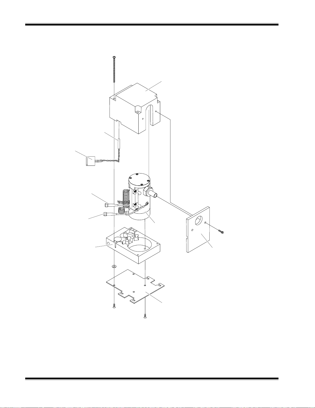
M
AINTENANCE AND TROUBLESHOOTING
RTD
RTD Cable
Cover
90V Cable
Signal Cable
Base
Burner
(see Figure 4-8)
Cover Plate
Mounting Plate
Note: This exploded view of the burner block is for information only. All
servicing of the burner block must be performed by Rosemount Analytical.
F
IGURE
4-6
4-7. B
URNER BLOCK
– E
XPLODED VIEW
November 1998 Rosemount Analytical 748364-DNGA 2000 FID 2 Analyzer Module
Page 59
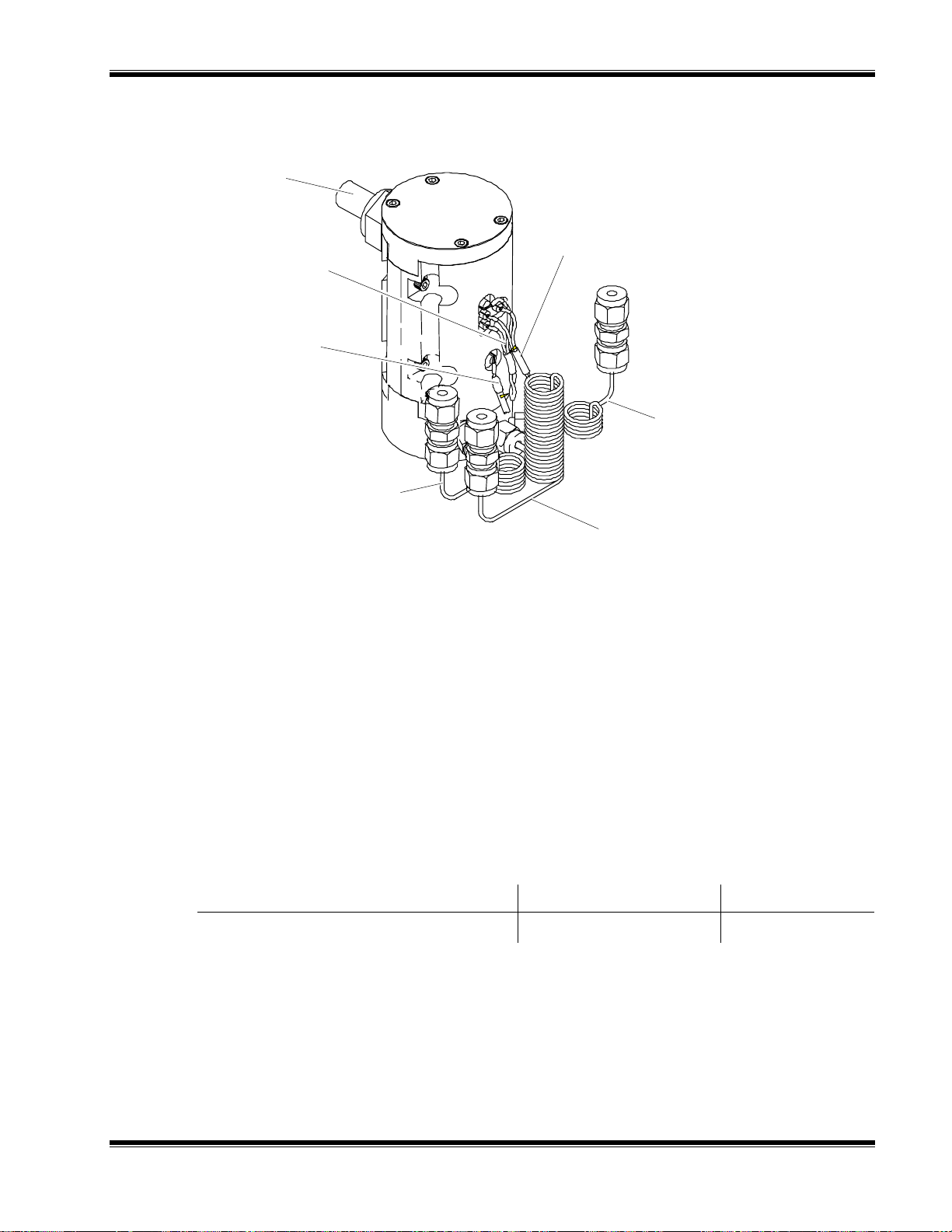
Exhaust
Ignitor Cable
(green)
90V Cable
(coax)
Air Capillary
M
AINTENANCE AND TROUBLESHOOTING
Thermistor Cable
(yellow)
Sample Capillary
Fuel Capillary
Note: This view of the burner is for information only. All servicing of the burner
must be performed by Rosemount Analytical.
F
IGURE
4-8. B
URNER
4.5 MAINTENANCE SCHEDULE
ITEM EVENT TIME
R
EPLACE EXHAUST TUBING
If plastic cracked Approx. 5 years
T
ABLE
748364-D Rosemount Analytical November 1998
4-1. M
AINTENANCE SCHEDULE
NGA 2000 FID 2 Analyzer Module
4-7
Page 60

M
AINTENANCE AND TROUBLESHOOTING
N
OTES
4-8
November 1998 Rosemount Analytical 748364-DNGA 2000 FID 2 Analyzer Module
Page 61

R
EPLACEMENT PARTS
5
5.1 REPLACEMENT PARTS
WARNING: PARTS INTEGRITY
Tampering with or unauthorized substitution of components may adversely
affect safety of this product. Use only factory-approved components for repair.
NL658350 Board Assembly, Computer
NL659060 Board Assembly, Module
NL659070 Board Assembly, Intrinsically safe
NL903347 Fuse, 6A (Main Power)
NL903823 Fuse, 4A (F2, F3 on Module Board)
NL903824 Fuse, 5A (F4, F5 on Module Board)
NL659063 Regulator
NL659225 Burner/Block Assembly
NL658144 Heater, Block
NL659043 Flow Control Manifold Assembly
The following components are selectable per application. Consult factory.
Fuel Capillary
Restrictor, Flow
Sample Capillary
748364-D Rosemount Analytical November 1998
NGA 2000 FID 2 Analyzer Module
5-1
Page 62

EPLACEMENT PARTS
R
N
OTES
5-2
November 1998 Rosemount Analytical 748364-DNGA 2000 FID 2 Analyzer Module
Page 63

A
PPENDIX
A. G
AS SAFETY FEATURES
A
A.1 GAS SAFETY FEATURES
The NGA 2000 Flame Ionization Detector Analysis Module is designed to meet
international safety standards in accordance with IEC 1010 and other related
documents. The gas handling part of the module is designed to be intrinsically safe,
other than the flame tower which is explosion proof (Ex"i" and Ex"d" respectively)
The standard module is only equipped to analyze a non-flammable sample, below
100% of the lower flammable limit.
WARNING: POSSIBLE EXPLOSION HAZARD
Protection against explosion depends upon a special fuel flow limiting restrictor
in fuel inlet fitting. Do not remove fuel inlet restrictor. Use the correct fuel flow
limiting restrictor for the fuel being used. Do not use 100% hydrogen fuel in a
40% H2/60% He configured Analysis Module. Replace only with factory supplied
fitting.
A.2 FUEL GAS OPTION
For the burner fuel gas, the standard analyzer requires 40% hydrogen and 60%
helium. Through the selection of the hydrogen fuel option, the analyzer can be
equipped to use 100% hydrogen fuel. This factory installed option can be ordered as a
matrix item.
The preferred type of fuel depends on the particular application and the characteristics
of the sample gas:
For measuring low-level hydrocarbons in ambient air, or in other sample gas with
relatively constant oxygen content, 100% hydrogen is preferable. It provides the
highest obtainable sensitivity and the maximum stability. Zero drift caused by ambient
temperature variations of the fuel cylinder is somewhat lower for 100% hydrogen than
for mixed fuel. (With either fuel, it is desirable to maintain cylinder temperature
constant.)
748364-D Rosemount Analytical November 1998
NGA 2000 FID 2 Analyzer Module
A-1
Page 64

PPENDIX
A
AS SAFETY FEATURES
A. G
For monitoring vehicular exhaust emissions, or other sample gas with varying oxygen
content, mixed fuel is preferable; and a hydrogen/helium mixture is more desirable
than a hydrogen/nitrogen mixture. With this type of sample, the use of mixed fuel gas
minimizes the error introduced by oxygen synergism.
An effective way to reduce the effect of internal oxygen is to dilute it with an inert gas.
This might be accomplished by a constant dilution of sample and calibration gases
ahead of the burner but it is simpler and more accurate to provide that diluent in the
form of premixed fuel. Both nitrogen and helium have been used as a diluent, but
helium has proven to be most effective in improving the equality of response to the
various species of hydrocarbons.
As indicated earlier the flame output signal is optimum when the ratio of hydrogen flow
to inert flow is about 40/60; therefore, this is the chosen composition for
hydrogen/helium premixed fuel.
The sample flow is kept low to maximize the dilution effect while still providing
adequate sensitivity. The burner air flow is normally about four times the fuel flow, and
changes have little effect on signal strength. For a given flow, the signal can be
optimized by adjusting the fuel flow rate.
l00 cc/min
10 cc/min
400 cc/min
T
ABLE
A-1. T
F
UEL
S
AMPLE
A
IR
YPICAL FLOW RATES WITH PREMIXED FUEL
It is worth noting that with a 40/60 premixed fuel, the above flows amount to 40 cc
(8%) hydrogen, 67 cc (13%) inert plus sample and 400 cc (79%) air, which compare
closely to the 30 cc (8%) hydrogen, 45 cc (12%) sample and 300 cc (80%) air given
earlier for straight hydrogen fuel.
Since the sample flow in the case of mixed fuel operation is only about one-sixth of
that with straight hydrogen fuel, it is clear that higher sensitivity is obtained with
straight hydrogen fuel operation. However, in any application where the sample
contains more than one species of hydrocarbon and/or a varying concentration of
oxygen, the mixed fuel operatio n shoul d be used .
The mixed fuel is recommended, not only for sample containing variable
concentrations of oxygen, but also for a specific pure gas application. If straight
oxygen samples are used with straight hydrogen fuel, the mixture entering the burner
is essentially 100% H2 which tends to produce an unstable signal. The mixed fuel
works better. Note that the choice of fuel determines certain analyzer characteristics
as tabulated in Table A-2.
A-2
November 1998 Rosemount Analytical 748364-DNGA 2000 FID 2 Analyzer Module
Page 65

PPENDIX
A
AS SAFETY FEATURES
A. G
T
ABLE
ANALYZER
CHARACTERISTICS
F
ULLSCALE SENSITIVITY
FUEL CONSUMPTION
O
PERATING RANGE FOR
S
AMPLE PRESSURE
REGULATOR
A-2. A
NALYZER CHARACTERISTICS FOR DIFFERENT FUELS
100% H
2
1 ppm, CH4 to 2%, CH
4
40% H2/60% HE
4 ppm, CH4 to <5%, CH
35 to 40 cc/min 80 to 100 cc/min
276 to 345 hPa-gauge (4
to 5 psig)
207 to 345 hPa-gauge (3
to 5 psig)
4
748364-D Rosemount Analytical November 1998
NGA 2000 FID 2 Analyzer Module
A-3
Page 66

PPENDIX
A
N
OTES
AS SAFETY FEATURES
A. G
A-4
November 1998 Rosemount Analytical 748364-DNGA 2000 FID 2 Analyzer Module
Page 67

A
PPENDIX
B. A
NALYZER SETUP CHECKLIST
B
B.1 ANALYZER SETUP CHECKLIST
The following checklist is designed to provide a series of steps that should be
undertaken during the installation process. The first step in troubleshooting an
analyzer system should be to go through this list making sure that all items have been
addressed.
B.1.1 S
B.1.2 A
AS MEASUREMENT PARAMETERS
G
YSTEM SETUP
!
Tags – each subnode
!
Module binding
!
Date and time
!
Security
!
Screen display
NALYZER MODULE SETUP
M
EASURED GAS
!
Name the gases
!
Set response factors (FID and McFID)
R
ANGES
!
Set all ranges
L
INEARIZATION
!
Edit coefficients
!
Assign curves to ranges
!
Enable curves
!
Mid point check
(N/A
FOR
MCFID)
R
ESPONSE TIME
!
Set response times
!
Set LON update time
748364-D Rosemount Analytical November 1998
NGA 2000 FID 2 Analyzer Module
B-1
Page 68

PPENDIX
A
NALYZER SETUP CHECKLIST
B. A
C
ALIBRATION GASES
!
Set zero and span gas levels for each range
ALIBRATION PARAMETERS
C
!
Set limit checking
!
Set timing
!
Set how it calibrates on ranges
HYSICAL MEASUREMENT PARAMETERS
P
!
Set all supporting gas pressures
!
Check sample gas flow
!
Light flame (FID, MCFID)
!
Set gas measurement (CLD)
ECHNICAL CONFIGURATION
T
!
Check gain
!
Check source current (IR)
!
Check oscillator tune (IR)
!
Check Chromatogram timings (MCFID)
ERO/SPAN ANALYZER
Z
!
Disable limit checking
!
Flow zero gas, zero the analyzer (optional for MCFID)
!
Flow span gas, span the analyzer
!
Enable limit checking
ERIFY LINEARITY (OPTIONAL
V
)
RESSURES AND FLOWS
- P
B-2
!
Connect a gas divider or set of calibration gases
!
Verify mid-range readings
!
If necessary, linearize the analyzer.
November 1998 Rosemount Analytical 748364-DNGA 2000 FID 2 Analyzer Module
Page 69

B.2 AUXILIARY MODULE SETUP
ARAMETERS
IO P
• Analog output type (voltage/current)
• Calibrate output
• Set output behavior on analyzer error
• Set auto-range change operation
• Set alarm relay behavior
UTOCALIBRATION PARAMETERS
A
• Set timing of overall operation
• Set master/slave relationships
• Set valve timing
PPENDIX
A
NALYZER SETUP CHECKLIST
B. A
• Set ranges to be calibrated
• (Single autocal only) Set analog output behavior
• Verify sample system operation
B.3 COMPUTER INTERFACE SETUP
• Install computer hardware
• Verify set up of hardware driver in CONFIG.SYS
• Install DDE server program
• Run the DDE server
• Debug the system if necessary with MAKE_API.EXE
• Set up applications
748364-D Rosemount Analytical November 1998
NGA 2000 FID 2 Analyzer Module
B-3
Page 70

PPENDIX
A
N
OTES
NALYZER SETUP CHECKLIST
B. A
B-4
November 1998 Rosemount Analytical 748364-DNGA 2000 FID 2 Analyzer Module
Page 71

A
PPENDIX
C. U
SER INTERFACE HELP
C
C.1 INSTRUCTIONS
This section provides a means of rapidly finding any desired function or configuration
factor in the menu system.
The NGA menu system is necessarily complex due to the wide variety of configuration
possibilities available with the NGA architecture.
This section consists of a series of titles describing the function or configuration
desired, with a series of menu titles that show the path taken to that function.
The menu selections are sometimes abbreviated; Basic Controls is referred to as
Basic for example, Expert controls and set up as Expert, and Technical level
configuration as Technical.
C.2 MENU ITEMS
LARM ENABLING
A
PATH: Technical - Diagnostics - Analyzer module diagnostics - Miscellaneous control
parameters
NALYZER TAG
A
PATH: Expert - Analyzer set up - Analyzer tag
PATH: Technical - Service - Manufacturing - Analyzer manufacturing data
Note: Set for each analyzer and also for each subnode
UTO-IGNITION ENABLED
A
PATH: Basic - Light flame – Autoignition
Note: Automates the light flame sequence, does not light without user prompting
though.
748364-D Rosemount Analytical November 1998
NGA 2000 FID 2 Analyzer Module
C-1
Page 72

PPENDIX
A
B
SER INTERFACE HELP
C. U
AROMETRIC PRESSURE
PATH: Expert - Analyzer set up - Physical measurement parameters - Pressure limits
Note: Reads data only from other bound analyzers
AROMETRIC PRESSURE COMPENSATION
B
PATH: Technical - Diagnostics - Analyzer module diagnostics - Primary variable
parameters - Barometric pressure compensation
Note: Only works if bound in a system with other analyzers
URNER AIR PRESSURE
B
PATH: Expert - Analyzer control - Physical measurements
PATH: Expert - Analyzer set up - Physical measurement parameters
PATH: Technical - Diagnostics - Analyzer module diagnostics - Physical measurement
parameters
URNER AIR PRESSURE ALARM LIMITS
B
PATH: Expert - Analyzer set up - Physical measurement parameters - Pressure limits
PATH: Technical - Diagnostics - Analyzer module diagnostics - Physical measurement
parameters
ALIBRATION ADJUSTMENT LIMIT
C
PATH: Expert - Analyzer set up - Calibration parameters - Calibration adjustment limits
Note: Enable to avoid incorrect calib rations
ALIBRATION ERROR ALLOWED
C
PATH: Expert - Analyzer set up - Calibration parameters - Calibration failure error
allowed
ALIBRATION FACTORS
C
PATH: Expert - Expert Analyzer controls - Zero/span calibration - FACTORS - NEXT
as desired
PATH: Technical - Diagnostics - Analyzer module diagnostics - Primary variable
parameters - Calibration factors – NEXT
C-2
ALIBRATION FAILURE ALARM
C
PATH: Expert - Analyzer set up - Calibration parameters - Calibration failure alarm
Note: Assigns calibration failure to general alarm variable
November 1998 Rosemount Analytical 748364-DNGA 2000 FID 2 Analyzer Module
Page 73

ALIBRATION FULL SCALE RANGE
C
PPENDIX
A
SER INTERFACE HELP
C. U
PATH: Expert - Expert Analyzer controls - Zero/span calibration - FACTORS – NEXT
ALIBRATION PRESSURE
C
PATH: Expert - Analyzer set up - Calibration gas list - Operational gas response factor
Note: Uses this to determine hardware range changes
ALIBRATION STATUS
C
PATH: Basic - Calibration status
Note: What the analyzer is doing now
APILLARY T Y PE
C
PATH: Technical - Service - Manufacturing - Analyzer module data - Fuel type
ATA STORAGE CONTROL
D
PATH: Technical - Diagnostics - Analyzer module diagnostics - Trend display control
Note: Stores data for 24 hours, but needs a PC to display it
ISPLAYED PARAMETERS
D
PATH: Expert - Analyzer set up - Displayed parameters
Note: Also select the source module in Control module menus
ISPLAYED UNITS
D
PATH: Expert - Analyzer set up - Gas measurement parameters - Units
NABLE LINEARIZER
E
PATH: Expert - Analyzer set up - Gas measurement parameters - Linearization
parameters
ILTER COEFFICIENTS
F
PATH: Technical - Diagnostics - Analyzer module diagnostics - Primary variable
parameters - Chromatogram filter order
Note: Filters the input to the chromatograph software.
LAME CONDITION
F
PATH: Basic - Flame status
PATH: Basic - Light flame - Flame status
Note: Light flame in menu under this
748364-D Rosemount Analytical November 1998
NGA 2000 FID 2 Analyzer Module
C-3
Page 74

PPENDIX
A
LAME DIAGNOSTICS
F
SER INTERFACE HELP
C. U
PATH: Basic - Light flame
PATH: Technical - Diagnostics - Analyzer module diagnostics - Auto ignition
parameters
Note: Shows pressures, status, etc.
UEL OVERRIDE DURATION
F
PATH: Technical - Diagnostics - Analyzer module diagnostics - Auto ignition
parameters
UEL PRESSURE
F
PATH: Expert - Analyzer control - Physical measurements
PATH: Expert - Analyzer set up - Physical measurement parameters
UEL PRESSURE ALARM LIMITS
F
PATH: Expert - Analyzer set up - Physical measurement parameters - Pressure limits
PATH: Technical - Diagnostics - Analyzer module diagnostics - Physical
measurement parameters
UEL STATUS
F
PATH: Technical - Diagnostics - Analyzer module diagnostics - Miscellaneous control
parameters
UEL TYPE
F
PATH: Technical - Diagnostics - Analyzer module diagnostics - Miscellaneous control
parameters
AS RESPONSE FACTOR
G
PATH: Expert - Analyzer set up - Calibration gas list - Calibration gas response factor
Note: Set to 1 for methane, 3.14 for propane
AS TYPE
G
PATH: Technical - Service - Manufacturing - Analyzer module data Minimum/maximum ranges and tags
C-4
Note: Set for each subnode
EATER CURRENTS
H
PATH: Technical - Diagnostics - Analyzer module diagnostics - Miscellaneous control
parameters
November 1998 Rosemount Analytical 748364-DNGA 2000 FID 2 Analyzer Module
Page 75

ISTORICAL CALIBRATION FACTORS
H
PPENDIX
A
SER INTERFACE HELP
C. U
PATH: Expert - Expert Analyzer controls - Zero/span calibration - FACTORS - Range
n factors - HISTORY
ISTORICAL PRESSURES AND FLOWS
H
PATH: Expert - Analyzer set up - Physical measurement parameters (press MORE)
PATH: Technical - Diagnostics - Analyzer module diagnostics - Physical
measurement parameters
Note: Values when analyzer was calibrated at the factory
YDROCARBON RESPONSE FACTOR
H
PATH: Expert - Analyzer set up - Chromatogram settings
Note: Set to 1 for methane, 3.14 for propane
GNITION PARAMETERS
I
PATH: Technical - Diagnostics - Analyzer module diagnostics - Auto ignition
parameters
N SERVICE DATE
I
PATH: Technical - Service - Service history - Analyzer module service history
AST SERVICE DATE
L
PATH: Technical - Service - Service history - Analyzer module service history
AST SPAN CALIBRATION DATE
L
PATH: Technical - Service - Service history - Analyzer module service history
PATH: Expert - Analyzer controls - Zero/span calibration - Result
AST ZERO CALIBRATION DATE
L
PATH: Technical - Service - Service history - Analyzer module service history
PATH: Expert - Analyzer controls - Zero/span calibration - Result
INEARIZER COEFFICIENTS
L
PATH: Expert - Analyzer set up - Linearizers, ranges and filters- Set coefficients
INEARIZER CORRECTION
L
PATH: Expert - Analyzer set up - Linearizers, ranges and filters
748364-D Rosemount Analytical November 1998
NGA 2000 FID 2 Analyzer Module
C-5
Page 76

PPENDIX
A
INEARIZER ENABLED
L
SER INTERFACE HELP
C. U
PATH: Expert - Analyzer control - Linearizers, ranges and filters
Note: Shows status
INEARIZER LIMITS
L
PATH: Expert - Analyzer set up Linearizers, ranges and filters- Set coefficients
INEARIZER STATUS
L
PATH: Expert - Analyzer set up - Linearizers, ranges and filters
INEARIZER USED
L
PATH: Expert - Analyzer set up - Linearizers ranges and filters
LON
UPDATE RATE
PATH: Expert - Analyzer set up - Linearizers, ranges and filters
M
AIN
ADC
VALUE
PATH: Technical - Diagnostics - Analyzer module diagnostics - Primary variable
parameters - Raw measurement signal
ANUFACTURING DATA – STORING
M
PATH: Technical - Service - Manufacturing - Analyzer module data - STORE
ANUFACTURING DATE
M
PATH: Technical - Service - Service history - Analyzer module service history
PATH: Technical - Service - Manufacturing data - Analyzer module data
ANUFACTURING DATE
M
PATH: Technical - Service - Manufacturing - Analyzer module data - Manufacturing
date
ANUFACTURING FACTORS
M
C-6
PATH: Expert - Expert Analyzer controls - Zero/span calibration - FACTORS - NEXT
ANUFACTURING ZERO/SPAN FACTOR
M
PATH: Expert - Expert Analyzer controls - Zero/span calibration - FACTORS - NEXT HISTORY
November 1998 Rosemount Analytical 748364-DNGA 2000 FID 2 Analyzer Module
Page 77

ETHANE VS. PROPANE
M
PPENDIX
A
SER INTERFACE HELP
C. U
PATH: Expert - Analyzer set up - Calibration gas list - Calibration gas response factor
Note: Set to 1 for methane, 3.14 for propane
OISE LEVEL
N
PATH: Technical - Diagnostics - Analyzer module diagnostics - Primary variable
parameters
RIGINAL PRESSURE AND FLOW SETTINGS
O
PATH: Expert - Analyzer set up - Physical measurement parameters (press MORE)
PATH: Technical - Diagnostics - Analyzer module diagnostics - Physical
measurement parameters
Note: Values when analyzer was calibrated at the factory
OWER SUPPLY VOLTAGES
P
PATH: Technical - Diagnostics - Analyzer module diagnostics - Power supply voltages
REAMP GAIN
P
PATH: Technical - Diagnostics - Analyzer module diagnostics - Primary variable
parameters
RESSURE COMPENSATION
P
PATH: Technical - Diagnostics - Analyzer module diagnostics - Primary variable
parameters - Barometric pressure compensation
RESSURES AND FLOWS
P
PATH: Expert - Analyzer control - Physical measurement
PATH: Technical - Diagnostics - Analyzer module diagnostics - Physical
measurement parameters
ROPANE VS. METHANE
P
PATH: Expert - Analyzer set up - Calibration gas list - Calibration gas response factor
Note: Set to 1 for methane, 3.14 for propane
URGE GAS SWITCH STATUS
P
PATH: Technical - Diagnostics - Analyzer module diagnostics - Miscellaneous control
parameters
748364-D Rosemount Analytical November 1998
NGA 2000 FID 2 Analyzer Module
C-7
Page 78

PPENDIX
A
SER INTERFACE HELP
C. U
PVA
FREQUENCY
PATH: Expert - Analyzer set up - Gas measurement parameters - Response
time/delay parameters
ANGE
R
PATH: Basic - Measurement range number
ANGE LIMIT – CURRENT
R
PATH: Basic - Range upper limit Not editable
ANGE LIMIT LIMITS
R
PATH: Technical - Service - Manufacturing - Analyzer module data - Range n upper
limit:
Note: Be careful!
ANGE LIMITS
R
PATH: Expert - Analyzer set up - Gas Measurement Parameters - Range settings
PATH: Expert - Analyzer controls - Range settings
Note: Limited by max. & min range in Manufacturing data screen
ANGES WITH VALID CALIBRATION
R
PATH: Basic - Ranges with valid calibration
Note: How many ranges were calibrated last time
AW SIGNAL
R
PATH: Technical - Diagnostics - Analyzer module diagnostics - Primary variable
parameters
EMOTE CONTROL
R
PATH: Basic – Control
Note: Requires an I/O module
ESETTING
R
EEPROM
PATH: Technical - Service - Manufacturing - Analyzer module data - RESET
ESETTING SOFTWARE ERRORS
R
C-8
PATH: Technical - Diagnostics - Analyzer module diagnostics - Software diagnostics
Note: Use “Edit to reset”
November 1998 Rosemount Analytical 748364-DNGA 2000 FID 2 Analyzer Module
Page 79

ESETTING STORED DATA
R
PPENDIX
A
SER INTERFACE HELP
C. U
PATH: Technical - Diagnostics - Analyzer diagnostics - Start up analyzer - INIT
ESPONSE TIME
R
PATH: N/A
Note: Not applicable for a GC.
ESTARTING ANALYZER
R
PATH: Technical - Diagnostics - Analyzer module diagnostics - Start up analyzer REBOOT
ESTORING SPAN AND ZERO FACTORS
R
PATH: Expert - Expert Analyzer controls - Zero/span calibration - FACTORS - Range
n factors - HISTOR Y - RSTR MN or RSTR ST
Note: MN = manufacturing data, ST = historical data
EVISION NUMBERS
R
PATH: Technical - Service - Manufacturing - Analyzer module data - software revision
number
Note: Not editable
AMPLE BYPASS FLOW
S
PATH: Expert - Analyzer control - Physical measurements
PATH: Expert - Analyzer set up - Physical measurement parameters
AMPLE BYPASS FLOW ALARM LIMITS
S
PATH: Expert - Analyzer control - Physical measurements
AMPLE FLOW
S
PATH: Basic - Bypass sample flow
AMPLE PRESSURE
S
PATH: Expert - Analyzer control - Physical measurements
PATH: Expert - Analyzer set up - Physical measurement parameters
AMPLE PRESSURE ALARM LIMITS
S
PATH: Expert - Analyzer set up - Physical measurement parameters - Pressure limits
748364-D Rosemount Analytical November 1998
NGA 2000 FID 2 Analyzer Module
C-9
Page 80

PPENDIX
A
S
SER INTERFACE HELP
C. U
CREEN DISPLAY LINES
PATH: Expert - Analyzer set up - Displayed parameters
Note: Also select the source module in Control module menus
ELF TEST
S
PATH: Technical - Diagnostics - Analyzer module diagnostics - Self test
ERIAL NUMBER
S
PATH: Technical - Service - Manufacturing - Analyzer module data - Serial number
ERVICE DATES
S
PATH: Technical - Service - Service history - Analyzer module service history
ERVICE NOTES
S
PATH: Technical - Service - Service history - Analyzer module service history
ET RANGE
S
PATH: Basic - Ranges
ETTING IGNITION PARAMETERS
S
PATH: Technical - Diagnostics - Analyzer module diagnostics - Auto ignition
parameters
IGNAL GAIN
S
PATH: Technical - Diagnostics - Analyzer module diagnostics - Primary variable
parameters
OFTWARE DIAG NOS TICS
S
PATH: Technical - Diagnostics - Analyzer module diagnostics - Software diagnostics
PAN RANGES SEPARATELY OR TOGETHER
S
PATH: Expert - Analyzer set up - Calibration parameters - Span ranges
Note: Doesn’t work if ranges span the main gain switch point
PAN ERROR MESSAGE
S
C-10
PATH: Basic - SPAN
November 1998 Rosemount Analytical 748364-DNGA 2000 FID 2 Analyzer Module
Page 81

PAN FACTOR
S
PPENDIX
A
SER INTERFACE HELP
C. U
PATH: Expert - Expert Analyzer controls - Zero/span calibration - FACTORS - Range
n factors
PATH: Technical - Diagnostics - Analyzer module diagnostics - Primary variable
parameters - Calibration factors - Range n factors
PAN FUNCTION
S
PATH: Basic - SPAN
PATH: Expert - Analyzer control - Zero/span calibration
Note: Doesn't control autocal
PAN GAS VALUES
S
PATH: Expert - Analyzer set up - Calibration gas list - NEXT as desired
TARTING ANALYZER
S
PATH: Technical - Diagnostics - Analyzer module diagnostics - Start up analyzer REBOOT
TORING SPAN AND ZERO DATA
S
PATH: Expert - Expert Analyzer controls - Calibration factors - NEXT - STORE
TAG
PATH: Expert - Analyzer set up - Analyzer tag
PATH: Technical - Service - Manufacturing - Analyzer manufacturing data
EMPERATURE ALARM LIMITS
T
PATH: Expert - Analyzer set up - Physical measurement parameters - Temperature
limits
EMPERATURE CONTROL PARAMETERS
T
PATH: Technical - Diagnostics - Analyzer module diagnostics - Temperature control
parameters
EMPERATURE MEASUREMENTS
T
PATH: Expert - Analyzer set up - Physical measurement parameters (press MORE)
748364-D Rosemount Analytical November 1998
NGA 2000 FID 2 Analyzer Module
C-11
Page 82

PPENDIX
A
REND DATA CONTROL
T
SER INTERFACE HELP
C. U
PATH: Technical - Diagnostics - Analyzer module diagnostics - Trend display control
Note: Stores data for 24 hours, but needs a PC to display it
NITS
U
PATH: Expert - Analyzer set up - Gas measurement parameters - Units
ALVE POSITION
V
PATH: Basic - Measurement cycle position
OLTAGES
V
PATH: Technical - Diagnostics - Analyzer module diagnostics - Power supply voltages
ERO ERROR MESSAGE
Z
PATH: Basic - ZERO
ERO FUNCTION
Z
ASIC
B
- ZERO
PATH: Expert - Analyzer control - Zero/span calibration
Note: Doesn't control autocal
ERO GAS VALUES
Z
PATH: Expert - Analyzer set up - Calibration gas list
ERO OFFSET
Z
PATH: Expert - Expert Analyzer controls - Calibration factors - NEXT
PATH: Technical - Diagnostics - Analyzer module diagnostics - Primary variable
parameters - Calibration factors - NEXT
ERO RANGES TOGETHER OR SEPARATELY
Z
PATH: Expert - Analyzer se t up - Calibration parameters - Zero ranges
Note: Doesn’t work if ranges span the main gain switch point
C-12
November 1998 Rosemount Analytical 748364-DNGA 2000 FID 2 Analyzer Module
Page 83

A
E
PPENDIX
D. FID 2 M
D.1 BASIC CONTROL MENUS
The softkey marked MENU leads to the "Main menu".
AIN MENU
M
:
Main Menu
Basic con t rols . . .
Expert controls and set up . . .
(Operational configuration)
Technical level configuration . . .
(Diagnostic and manufacturing/service)
DISPLAY PARMS. NEXT LOCK INFO
ENU STRUCTURE
D
IGURE
F
ASIC CONTROLS MENU
B
F
IGURE
D-1. M
Three divisions, corresponding to Operation, set up (and advanced operation), and
diagnostics and support.
AIN MENU
:
Basic Controls
Measurement range number:
Range upper limit:
Range and functional control:
Bypass sample flow:
Ranges with valid calibration:
Calibration status:
If it won’t calibrate:
Flame condition:
Light Flame . . .
HOME ESCAPE ZERO SPAN INFO
D-2. B
CURRENTRNGHI shows the current value of the active range full scale limit.
ASIC CONTROL MENU
CRANG
CURRENTRNGHI
CONTROL
FLOW_IS (1)
CAL_VALIDITY
CALSTAT
DIGDIAG (5)
748364-D Rosemount Analytical November 1998
NGA 2000 FID 2 Analyzer Module
D-1
Page 84

PPENDIX
A
D. FID 2 M
ENU STRUCTURE
CONTROL allows an I/O module to control the ranges; it doesn’t affect a PC.
CAL_VALIDITY shows the ranges that were validly calibrated during the last
calibration performed.
CALSTAT shows whether the unit is currently calibrating, providing feedback when
the ZERO or SPAN softkeys are pressed.
NALYZER ZERO MENU
A
:
Analyzer zero
Are you sure?
You must have zero gas flowing through the
analyzer. . .
This control does NOT control any auto-calibration
module bound to this analyzer!
If you are sure, press ZERO again now.
Press the left arrow key when you are done.
Calibration status:
Error message for last zero:
CAL_ERR_MSG (1)
CALSTAT
HOME ESCAPE ZERO INFO
F
IGURE
D-3. Z
ERO “ARE YOU SURE
?” M
ENU
ZERO will measure the zero gas, mon itor the reading for stability and adju st the zero
factor until the reading is within 0.02% of the current fullscale range, of the target zero
value.
The span menu is similar.
IGHT FLAME MENU
L
:
Flame condition:
Auto-ignition:
Ignition system enable:
Number of ignition attempts so far:
Time on this cycle – s ecs:
Fuel supply pressure:
Burner air pressure:
Sample pressure:
Flame temperature:
Status:
Light Flame
DIGDIAG (5)
AUTOIGNITE
FUEL_FLOW
TIME_LEFT (2)
TIME_LEFT (1)
PRES_IS (3)
PRES_IS (2)
PRES_IS (1)
TEMP_IS (2)
FID_MSGE
F
IGURE
D-2
D-4. L
HOME ABORT LIGHT INFO
IGHT FLAME MENU
November 1998 Rosemount Analytical 748364-DNGA 2000 FID 2 Analyzer Module
Page 85

PPENDIX
A
D. FID 2 M
ENU STRUCTURE
Auto-ignition refers to the unit's automatically enriching the mixture and going
through its ignite sequence, not re-lighting the flame if it has gone out. This latter is
not available for safety reasons.
To start cycle, press LIGHT softkey. The unit will attempt ignition cycle until the flame
is on, or the selected number of cycles is completed.
When no ignition results, a failure message will appear at the bottom of the screen.
D.2 EXPERT CONTROL MENUS
Starting with the main menu again:
Main Menu
Basic controls . . .
Expert controls and set up . . .
(Operational configuration)
Technical level configuration. . .
(Diagnostic and manufacturing/ser vice)
DISPLAY PARMS. NEXT LOCK INFO
F
IGURE
XPERT CONTROLS AND SET UP MENU
E
F
IGURE
D-5. M
D-6. E
AIN MENU
:
Expert controls and set up
Expert analyzer controls . . .
Auxiliary module controls . . .
System set up . . .
Analyzer module set up . . .
Auxiliary module set up . . .
HOME ESCAPE NEXT INFO
XPERT CONTROLS AND SETUP MENU
Select the module (or subnode via NEXT) to control or set up.
748364-D Rosemount Analytical November 1998
NGA 2000 FID 2 Analyzer Module
D-3
Page 86

PPENDIX
E
A
XPERT CONTROLS MENU
E
D. FID 2 M
ENU STRUCTURE
:
Expert Controls
Measurement range number:
Ranges upper limit:
Range settings . . .
Linearizer:
Range and functional control:
Zero/span calibration. . .
Ranges with valid calibration:
Physical measurements:
Measurement cycle mode:
Flame condition:
Light Flame . . .
HOME ESCAPE CAL CAL DATA INFO
CRANGE
CURRENTRNGHI
CURRENTLSTAT
CONTROL
CAL_VALIDITY
DIGDIAG (5)
F
IGURE
D-7. E
XPERT CONTROLS MENU
Similar to basic controls except with more information.
ANGE SETTINGS MENU
R
F
IGURE
D-8. R
ANGE SETTINGS MENU
:
Range Settings
Minimum range:
Maximum range:
Range 1 lower limit:
Range 1 upper limit:
Range 2 lower limit:
Range 2 upper limit:
Range 3 lower limit:
Range 3 upper limit:
Range 4 lower limit:
Range 4 upper limit:
HOME ESCAPE INFO
MINRANG
MAXRANGE
RNGLO (1)
RNGHI (1)
RNGLO (2)
RNGHI (2)
RNGLO (3)
RNGHI (3)
RNGLO (4)
RNGHI (4)
Minimum and maximum ranges are set in the manufacturing data menu, and can't be
edited here. You can't edit a range to a higher or lower value than these, respectively.
D-4
November 1998 Rosemount Analytical 748364-DNGA 2000 FID 2 Analyzer Module
Page 87

PPENDIX
E
A
D. FID 2 M
ENU STRUCTURE
ERO/SPAN CALIBRATION MENU
Z
Measurement range number:
Zero gas concentrations:
Span gas concentrations:
Bypass sample flow:
Flame condition:
Raw measurement signal:
Status:
Result. . .
Calibration adjustment limits:
HOME SPANZERO INFO
F
IGURE
D-9. Z
ERO/SPAN CALIBRATION MENU
ERO
– Z
Zero/span calibration
FACTORS
:
CRANG
CURRENTZERO
CURRENTSPAN
FLOW_IS (1)
DIGDIAG (5)
RAW_SIGNAL
CALSTAT
CALCHKLIMITS
- Z
ERO
FACTORS leads to the calibration factors menu, see the appropriate section below.
ZERO leads to the zero menu.
SPAN leads to the span menu.
Result. . . leads to a menu that shows the results of the most recent calibration.
NALYZER ZERO MENU
A
F
IGURE
D-10. A
NALYZER ZERO MENU
:
Analyzer zero
Are you sure?
You must have zero gas flowing through the
analyzer. . .
This control does NOT control any auto- c alibr ation
module bound to this analyzer!
If you are sure, press ZERO again now.
Press the left arrow key when you are done.
Calibration status:
Error message for last zero:
HOME ESCAPE ZERO INFO
CAL_ERR_MSG (1)
CALSTAT
Press ZERO again to make the analyzer perform zero.
748364-D Rosemount Analytical November 1998
NGA 2000 FID 2 Analyzer Module
D-5
Page 88

PPENDIX
Z
A
ERO/SPAN DIAGNOSTIC DATA MENU
Z
D. FID 2 M
ENU STRUCTURE
Date of last zero:
Error message for last zero:
Error percentage for last zero:
Raw signal at last zero:
Last zero gas would read:
Date of last span:
Error message for last span:
Error percentage for last span:
Raw signal at last span:
The last span gas would read:
HOME ESCAPE FACTORS INFO
:
Zero/span diagnostic data
CALDATE_
CAL_ERR_MSG (1)
CALRESULT (1)
CAL_RAWSIG (1)
LASTZERO
CALDATE_S
CAL_ERR_MSG (2)
CALRESULT (2)
CAL_RAWSIG (2)
LASTSPAN
F
IGURE
D-11. Z
ERO/SPAN DIAGNOSTIC DATA MENU
LASTZERO and LASTSPAN show what the last zero and span would have read if the
most recent calibration factors had been used to measur e those gases .
FACTORS once again leads to the calibration factors menus.
(Also Light Flame as under Basic Controls)
D.3 ANALYZER SETUP MENUS
Starting from the Expert controls and setup. . .
NALYZER MODULE SET UP MENU
A
Calibration gas list. . .
Calibration parameters. . .
Gas measurement parameter s . . .
Analyzer parameter list. . .
Physical measurement param eters. . .
Displayed parameters. . .
Analyzer tag:
:
Analyzer module set up
TAG
F
IGURE
D-6
HOME ESCAPE STORE INFO
D-12. A
NALYZER MODULE SET UP MENU
TAG contains the name you can assign to this analyzer, and you can address it by this
name using the DDE server in a PC.
November 1998 Rosemount Analytical 748364-DNGA 2000 FID 2 Analyzer Module
Page 89

ALIBRATION GAS LIST MENU
C
PPENDIX
A
:
Calibration gas list
Zero gas – range 1:
Span gas – range 1:
Zero gas – range 2:
Span gas – range 2:
Zero gas – range 3:
Span gas – range 3:
Zero gas – range 4:
Span gas – range 4:
Calibration gas HC response factor:
Calibration. . .
HOME ESCAPE INFO
ZEROGAS (1)
ZEROGAS (1)
ZEROGAS (2)
ZEROGAS (2)
ZEROGAS (3)
ZEROGAS (3)
ZEROGAS (4)
ZEROGAS (4)
CARBON_ATOMS
D. FID 2 M
ENU STRUCTURE
F
IGURE
D-13. C
ALIBRATION GAS LIST MENU
This menu shows the calibration gases for each range, and the response factor both
for these gases and for the main measurement. This variable CARBON_ATOMS
determines the measurement units, whether in methane or other, such as propane,
terms. The calibration gases must be entered in the same terms as those for the
measurement – if the measurement is in methane terms, the calibration also has to be
in methane terms.
(Leads to expert calibration menu above.)
ALIBRATION PARAMETERS MENU
C
Calibration adjustment limits :
Calibration averaging time:
Calibration failure alarm :
Cal failure error allowed:
Calibration time out:
Zero ranges:
Span ranges:
:
Calibration parameters
CALCHKLIMITS
CALTIME
CALFAIL
CALFPC
CALTIMEOUT
ZERORNGS
ZPANRNGS
HOME ESCAPE INFO
F
IGURE
D-14. C
ALIBRATION PARAMETERS MENU
CALCHKLIMITS if enabled forces the analyzer not to accept a calibration if the
calibration gas is more than CALFPC away from the target (as a percentage of the
current fullscale range). If disabled it allows calibration no matter how far off the
measurement is.
CALTIME sets the time over which the analyzer averages good measurement during
the calibration cycle. This value should normally be left in the default setting.
748364-D Rosemount Analytical November 1998
NGA 2000 FID 2 Analyzer Module
D-7
Page 90

PPENDIX
A
D. FID 2 M
ENU STRUCTURE
CALFAIL enables (or disables) the specific calibration failure alarm. If the analyzer
determines that it cannot perform any of the possible calibrations, the calibration
failure specific alarm will be set if CALFAIL is enabled.
CALFPC determines the allowable calibration error if CALCHKLIMITS is enabled.
CALFPC is a percentage of the range on which the calibration is currently being
performed. It is normally left at 5%.
CALTIMEOUT determines how long the analyzer will wait for a stable reading before
performing the calibration. Once this time has passed, the analyzer will calibrate
anyway, though if the result is out of the CALFPC limits and CALCHKLIMITS is set,
the calibration will not be accepted.
ZERORNGS determines whether the analyzer will attempt to zero all the ranges at
once (see the discussion elsewhere on the po ssibility of this).
CALRANGES allows you to calibrate all the ranges at once, if the calibration gas is
less than 110% of the fullscale value of each range.
AS MEASUREMENT PARAMETERS MENU
G
:
From the Analyzer Module set up menu leads to the following menu:
Gas measurement parameters
Linearization parameters. . .
Response time/delay parameters. . .
Range settings. . .
Units. . .
Linearization functions. . .
HOME ESCAPE INFO
F
IGURE
D-15. G
AS MEASUREMENT PARAMETERS MENU
Linearization parameters leads to the linearization menus.
D-8
You can assign any of the four available polynomial linearizers to any range. See the
menus below for this.
November 1998 Rosemount Analytical 748364-DNGA 2000 FID 2 Analyzer Module
Page 91
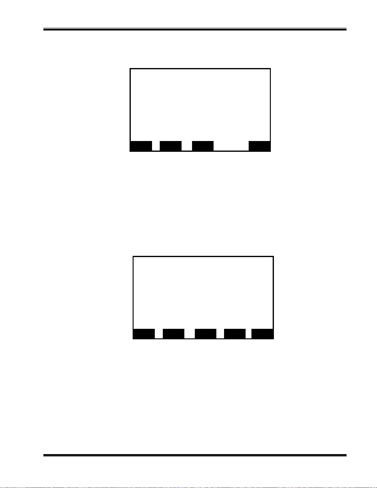
INEARIZATION PARAMETERS MENU
L
Measured gas:
Range 1 linearizer:
If enabled, uses curve no.:
Range 2 linearizer:
If enabled, uses curve no.:
Range 3 linearizer:
If enabled, uses curve no.:
Range 4 linearizer:
If enabled, uses curve no.:
Set coefficients. . .
:
Linearization parameters
PPENDIX
A
GAS
LINSTAT (1)
LINFORRANGE (1)
LINSTAT (2)
LINFORRANGE (2)
LINSTAT (3)
LINFORRANGE (3)
LINSTAT (4)
LINFORRANGE (4)
D. FID 2 M
ENU STRUCTURE
F
IGURE
D-16. L
HOME ESCAPE INFO
INEARIZA TION PARAMETERS
NEXT
Sets up the operation of the linearizer if any on the range identified by
LINFORRANGE. Note that you can set up the same linearizer to operate on any
number of ranges – but you’ll use the same curve on all of them. Generally
linearization should not be necessary.
INEARITY COEFFICIENTS MENU
L
Curve 1
A0 coefficient:
A1 coefficient:
A2 coefficient:
A3 coefficient:
A4 coefficient:
Curve upper limit:
Curve over-range:
Curve under-range:
Status:
:
Linearity coefficients
LINA0_(1)
LINA1_(1)
LINA2_(1)
LINA3_(1)
LINA4_(1)
LINRNGHI (1)
LIN_OVER (1)
LIN_UNDER (1)
LINSTAT (1)
F
IGURE
D-17. L
HOME ESCAPE INFO
INEARITY COEFFICIENTS MENU
NEXT LAST
Curve 2, 3, 4 menus are similar. The coefficients must add up to 1 to within 0.2% to
achieve a 0.2% linearity. The A0 coefficient is the zero offset, and it should normally
be set to zero. The upper limit shows the range over which the linearizer can work –
and the over and under range percentages show the limit points.
Outside this range the transfer function will be a straight line whose slope is the
gradient of the linearizer curve at the end point. This stops an inflected curve from
playing havoc with the calibration algorithms.
748364-D Rosemount Analytical November 1998
NGA 2000 FID 2 Analyzer Module
D-9
Page 92

PPENDIX
A
D. FID 2 M
ENU STRUCTURE
Also, the curve must be uninflected! Any negative slope will make the calibration fail.
The analyzer will detect this and fail to calibrate.
ESPONSE TIME/DELAY PARAMETERS MENU
R
Response time/delay parameters
Range 1 t90 time:
Range 2 t90 time:
Range 3 t90 time:
Range 4 t90 time:
:
AFT90_(1)
AFT90_(2)
AFT90_(3)
AFT90_(4)
F
IGURE
D-18. R
LON update rate:
Output delay time:
HOME ESCAPE INFO
ESPONSE TIME/DELAY PARAMETERS MENU
LONPVUPDATE
AMDELAYTIME
AFT90_ determines the filtering applied to each range. The time value is the time
constant of the filter applied. This value also affects the degree of the median filter
used.
The LONPVUPDATE variable controls how fast the analyzer puts the PVA signal (the
main reading) onto the LON network. For normal operation this should be set to 10
samples per second, but for fastest performance set it to ASAP. If you have more
than four analyzers on one network, setting all the analyzers to ASAP may overload
the network, showing up as sluggish menu response. In this case, set them to 10 per
second.
AMDELAYTIME determines the group delay of the PVA signal from this analyzer. It
may be set between 0 and 30 seconds. Its effect is to delay the PVA from this
analyzer by that amount, useful if you are trying to synchronize several analyzers that
are measuring a common sample.
D-10
November 1998 Rosemount Analytical 748364-DNGA 2000 FID 2 Analyzer Module
Page 93

NITS MENU
U
PPENDIX
A
D. FID 2 M
ENU STRUCTURE
:
Units
Gas measurement units:
Pressure measurement units:
Temperature measurement units:
ppm to mg/Nm3 convers ion factor:
Variables are still sent as t he bas ic S I unit.
HOME ESCAPE INFO
PVU
PPU
PTU
PPM2MG
F
IGURE
D-19. U
NITS MENU
Controls the units of these values as displayed on the control module screen and as
reported by the DDE server when in "Native" mode. The actual variable contents are
always in SI units.
The SI pressure unit is hPa (hecto-Pascals). These are supposed to be absolute
pressures, but enough people find this confusing that we decided to report them as
gauge pressures instead, using hPa as the "unit". Generally (except for barometric
pressure readings) all NGA pressure readings are gauge.
Range settings are as described above.
Linearization functions leads to a series of screens that support such self-linearization
capabilities as this analyzer has. As with most NGA analyzers, the polynomial selflinearization function is not enabled, while the mid-point correction is. The former
menus are not described here. The midpoint correction allows you to set up to 3 mid
points as well as the zero and span point for each range, such that the analyzer’s
transfer function is a series of straight lines passing through these points. This
correction is in addition to any polynomial linearization applied. This function may be
used to force agreement with arbitrary mid-point gases whose values are accepted for
regulatory reasons, despite any evidence to the contrary.
748364-D Rosemount Analytical November 1998
NGA 2000 FID 2 Analyzer Module
D-11
Page 94
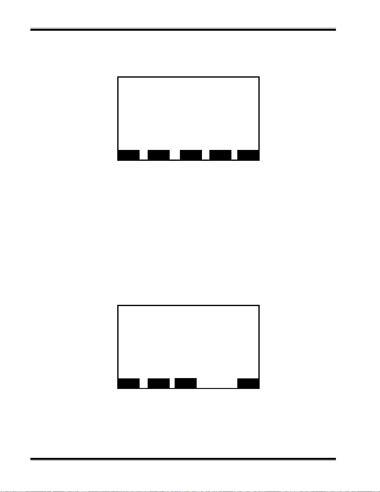
PPENDIX
A
IDPOINT CORRECTION SET UP MENU
M
D. FID 2 M
ENU STRUCTURE
Range 1
Correction:
Point being measured:
Point 1 gas concentration:
Point 2 gas concentration:
Point 3 gas concentration:
Point 1 reading:
Point 2 reading:
Point 3 reading:
Span gas value:
Analyzer functioning:
:
Midpoint correction set up
TWEAK (1)
MEASUREPOINT
MID_GASA (1)
MID_GASA (2)
MID_GASA (3)
MIDPOINTA ( 1)
MIDPOINTA ( 2)
MIDPOINTA ( 3)
SPAN_THEN (1)
MEAS_STAT
F
IGURE
D-20. M
HOME ESCAPE INFO
IDPOINT CORRECTION SET UP MENU
SET RANGE 2
TWEAK enables this function. Set this to enabled after you have performed the
following procedure.
Set the point to be measured with MEASUREPOINT. Set its intended value with
MID_GASA(1). Allow the gas to flow, and when the reading has stabilized, press SET
softkey. Repeat with MID_GASA (2) and MID_GASA (3).
The current span gas value is stored in SPAN_THEN for this range.
MEAS_STAT tells you what the analyzer is doing while you are doing this.
HYSICAL MEASUREMENT PARAMETERS MENU
P
Physical measurement parameters
Sample capillary pressure:
Sample capillary pressure was:
Fuel supply pressure:
Fuel supply pressure was:
Burner air pressure:
Burner air pressure was:
:
PRES_IS (1)
P_WAS (1)
PRES_IS (3)
P_WAS (3)
PRES_IS (2)
P_WAS (2)
F
IGURE
D-12
Pressure limits. . .
Temperature limit s . . .
MORE
D-21. P
HOME ESCAPE INFO
HYSICAL MEASUREMENT PARAMETERS MENU
This menu shows the current values of the various pressures, together with their
values when they were stored. Pressure are quite critical, so this screen should be
examined if the analyzer does not seem to be performing correctly.
November 1998 Rosemount Analytical 748364-DNGA 2000 FID 2 Analyzer Module
Page 95

PPENDIX
A
D. FID 2 M
ENU STRUCTURE
Temperatures and bypass sample flow are shown on the menu linked to the MORE
softkey.
HYSICAL MEASUREMENT PARAMETERS MENU (MORE
P
Physical measurement parameters
Bypass sample flow:
Bypass sample flow was:
Block temperature:
Block temperature was:
Flame temperature:
Flame temperature was:
Preamplifier temperature:
Preamplifier temperature was:
HOME ESCAPE INFO
):
FLOW_IS (1)
FLOW_WAS (1)
TEMP_IS (1)
TEMP_WAS (1)
TEMP_IS (2)
TEMP_WAS (2)
TEMP_IS (3)
TEMP_WAS (3)
F
IGURE
RESSURE LIMITS MENU AND TEMPERATURE LIMITS MENU
P
D-22. P
HYSICAL MEASUREMENT PARAMETERS
(MORE) M
:
ENU
Pressure and temperature alarm limits are shown on the next two screens. These
menus allow you to set the diagnostic limits to the pressure and temperature values. If
the limits are exceeded, and alarms are enabled, a WARNING alarm will be issued
and GENERALSTATE will show the value WARNING also.
Pressure limits
Sample capillary upper limit:
Sample capillary lower limit:
Fuel pressure upper list:
Fuel pressure lower limit:
Burner air upper limit:
Burner air lower limit:
Barometric pressure:
PLIM (1)
PLIM (2)
PLIM (3)
PLIM (4)
PLIM (5)
PLIM (6)
BAROMETER
HOME ESCAPE INFO
F
IGURE
748364-D Rosemount Analytical November 1998
D-23. P
RESSURE LIMITS MENU
NGA 2000 FID 2 Analyzer Module
D-13
Page 96

PPENDIX
A
D. FID 2 M
ENU STRUCTURE
This also shows the barometric pressure read from another analyzer itself capable of
reading this. This value will only be updated if that other analyzer is set to put its
barometric pressure out on the network, and then only if there is a control module also
on the network.
Temperature limits
Block upper limit:
Block lower limit:
Flame upper limit:
Flame lower limit:
Preamp upper limit:
Preamp lower limit:
HOME ESCAPE INFO
TLIMA (1)
TLIMA (2)
TLIMA (3)
TLIMA (4)
TLIMA (5)
TLIMA (6)
F
IGURE
D-24. T
EMPERATURE LIMITS MENU
Back to the Analyzer module set up menu: It next leads to this…
ISPLAYED PARAMETERS MENU
D
F
IGURE
D-25. D
First line’s paramet er:
Second line’s parameter:
Third line’s parameter:
Fourth line’s parameter:
May be displayed on the appropriate line of
the single analyzer display screen.
HOME ESCAPE INFO
ISPLAYED PARAMETERS MENU
:
Displayed parameters
SVNAME (1)
SVNAME (1)
SVNAME (1)
SVNAME (1)
D-14
Used in conjunction with the display selection menus in the system set up section of
the control module menus. The lines referred to are the auxiliary lines on the single
output display screen.
TAG is the means of identifying this analyzer on the main display screens and also
through the DDE server.
In the analyzer set up menu the softkey STORE leads to the following:
November 1998 Rosemount Analytical 748364-DNGA 2000 FID 2 Analyzer Module
Page 97

TORE/RESTORE USER SETTING MENU
S
Are you sure?
STORE button saves various user settings for
later use.
RESTORE will restore the previously saved
user settings.
:
Store/Restore user settings
A
PPENDIX
D. FID 2 M
ENU STRUCTURE
F
IGURE
D-26. S
HOME ESCAPE STORE INFO
TORE/RESTORE USER SETTING MENU
RESTORE
STORE stores all the configuration variables into the “ZZ” prefixed variable set.
RESTORE restores them all into the current variables.
D.4 ANALYZER TECHNICAL CONFIGURATION MENUS
Once again starting with the Main menu…
Main Menu
Basic controls . . .
Expert controls and set up . . .
(Operational configuration)
Technical level configuration. . .
(Diagnostic and manufacturing/ser vice)
DISPLAY PARMS. NEXT LOCK INFO
F
IGURE
748364-D Rosemount Analytical November 1998
D-27. M
AIN MENU
NGA 2000 FID 2 Analyzer Module
D-15
Page 98

A
PPENDIX
ECHNICAL CONFIGURATION MENU
T
D. FID 2 M
ENU STRUCTURE
System set up . . .
Service menus . . .
Diagnostic menus . . .
Other module diagnostic m enus . . .
Listing of all modules . . .
HOME ESCAPE NEXT INFO
:
Technical configuration menu
F
IGURE
ERVICE MENUS
S
F
IGURE
ANUFACTURING DATA MENU
M
D-28. T
D-29. C
ECHNICAL CONFIGURATION MENU
:
ONTROL MODULE SERVICE MENU
Service Menus
Manufacturing data . . .
Service history . . .
In maintenance since:
Record security codes . . .
HOME ESCAPE INFO
MAINTSINCE
:
Manufacturing data
Control Module data. . .
Analyzer module data. . .
F
IGURE
D-16
D-30. C
HOME ESCAPE MORE BACK INFO
ONTROL MODULE MANUFACTURING DATA SELECTION MENU
November 1998 Rosemount Analytical 748364-DNGA 2000 FID 2 Analyzer Module
Page 99

N
NALYZER MANUFACTURING DATA MENU
A
Analyzer manufacturing data
Analyzer module s/n:
Manufacturing date code:
Hardware revision number:
Software revision number:
Minimum range:
Maximum range:
Measured gas:
HOME ESCAPE RESET STORE INFO
A
PPENDIX
D. FID 2 M
ENU STRUCTURE
:
AMS
AMMFGDATE
AMHR
AMSR
MINRANGE
MAXRANGE
GAS
F
IGURE
D-31. A
NALYZER MANUFACTURING DATA
Shows the original manufacturing data (unless you have edited it!)
RESET will restore the PROM default values of all the variables, erasing ALL the
calibration, set up and manufacturing data. There is an “Are you sure?” menu under
this so ftkey.
STORE will store current values into all of the “Was” lines in the diagnostic menus
below. Press this softkey when you are sure that the unit is operating correctly to get
a reference for the future.
ERVICE HISTORY MENU
S
:
Servic e H i story
Control module history. . .
Analyzer module history. . .
HOME ESCAPE INFO
D-32. C
ONTROL MODULE SERVICE HISTORY SELECTION MENU
F
IGURE
748364-D Rosemount Analytical November 1998
MORE BACK
NGA 2000 FID 2 Analyzer Module
D-17
Page 100

A
E
PPENDIX
NALYZER MODULE SERVICE HISTORY MENU
A
D. FID 2 M
ENU STRUCTURE
Manufacturing date:
In servcie date:
Last zero calibration date:
Last span calibration date:
Last service date:
List notes . . .
Add service date!
HOME ESCAPE INFO
Analyzer module service history
:
AMMFGDAT
AMSERVDATE
CALDATE_Z
CALDATE_S
AMLSDATE
F
IGURE
D-33. A
NALYZER SERVICE HISTORY MENU
Service people enter service dates and list notes as to what service was performed.
NALYZER MODULE SERVICE NOTES MENU
A
F
IGURE
D-34. A
Analyzer module service notes
Up to 22 characters can be written in each line.
HOME ESCAPE INFO
NALYZER MODULE SERVICE NOTES
:
ANALSERNOTEA
ANALSERNOTEB
ANALSERNOTEC
ANALSERNOTED
ANALSERNOTEE
ANALSERNOTEF
ANALSERNOTEG
ANALSERNOTEH
ANALSERNOTEI
ANALSERNOTEJ
There is a list of service abbreviations in the control module help for the equivalent
menu. The service performed and date are enter here.
D-18
November 1998 Rosemount Analytical 748364-DNGA 2000 FID 2 Analyzer Module
 Loading...