


Model 700 Gas Chromatograph
Applies to the Rosemount® Analytical Model 700 and
the Danalyzer™ Model 700
System Reference Manual
Revision P
3-9000-521
April 2012

NOTICE
ROSEMOUNT ANALYTICAL, INC. AND DANIEL MEASUREMENT AND CONTROL, INC. (COLLECTIVELY,
“SELLER”) SHALL NOT BE LIABLE FOR TECHNICAL OR EDITORIAL ERRORS IN THIS MANUAL OR OMISSIONS
FROM THIS MANUAL. SELLER MAKES NO WARRANTIES, EXPRESSED OR IMPLIED, INCLUDING THE IMPLIED
WARRANTIES OF MERCHANTABILITY AND FITNESS FOR A PARTICULAR PURPOSE WITH RESPECT TO THIS
MANUAL AND, IN NO EVENT, SHALL SELLER BE LIABLE FOR ANY SPECIAL OR CONSEQUENTIAL DAMAGES
INCLUDING, BUT NOT LIMITED TO, LOSS OF PRODUCTION, LOSS OF PROFITS, ETC.
PRODUCT NAMES USED HEREIN ARE FOR MANUFACTURER OR SUPPLIER IDENTIFICATION ONLY AND MAY
BE TRADEMARKS/REGISTERED TRADEMARKS OF THESE COMPANIES.
THE CONTENTS OF THIS PUBLICATION ARE PRESENTED FOR INFORMATIONAL PURPOSES ONLY, AND
WHILE EVERY EFFORT HAS BEEN MADE TO ENSURE THEIR ACCURACY, THEY ARE NOT TO BE CONSTRUED
AS WARRANTIES OR GUARANTEES, EXPRESSED OR IMPLIED, REGARDING THE PRODUCTS OR SERVICES
DESCRIBED HEREIN OR THEIR USE OR APPLICABILITY. WE RESERVE THE RIGHT TO MODIFY OR IMPROVE
THE DESIGNS OR SPECIFICATIONS OF SUCH PRODUCTS AT ANY TIME.
SELLER DOES NOT ASSUME RESPONSIBILITY FOR THE SELECTION, USE OR MAINTENANCE OF ANY
PRODUCT. RESPONSIBILITY FOR PROPER SELECTION, USE AND MAINTENANCE OF ANY SELLER PRODUCT
REMAINS SOLELY WITH THE PURCHASER AND END-USER.
DANIEL AND THE DANIEL LOGO ARE REGISTERED TRADEMARKS OF DANIEL MEASUREMENT AND
CONTROL, INC. ROSEMOUNT AND THE ROSEMOUNT ANALYTICAL LOGO ARE REGISTERED TRADEMARKS
OF ROSEMOUNT ANALYTICAL. THE EMERSON LOGO IS A TRADEMARK AND SERVICE MARK OF EMERSON
ELECTRIC CO.
©2012
ROSEMOUNT ANALYTICAL, INC.
DANIEL MEASUREMENT AND CONTROL, INC.
HOUSTON, TX
USA
All rights reserved. No part of this work may be reproduced or copied in any form or by any means–graphic,
electronic, or mechanical–without first receiving the written permission of Rosemount Analytical Inc. or Daniel
Measurement and Control, Inc., Houston, Texas, U.S.A.

WARRANTY
1. LIMITED WARRANTY: Subject to the limitations contained in Section 2 herein and except as otherwise
expressly provided herein, Rosemount Analytical and Daniel Measurement and Control, Inc., (collectively
“Seller”) warrants that the firmware will execute the programming instructions provided by Seller, and that
the Goods manufactured or Services provided by Seller will be free from defects in materials or
workmanship under normal use and care until the expiration of the applicable warranty period. Goods are
warranted for twelve (12) months from the date of initial installation or eighteen (18) months from the
date of shipment by Seller, whichever period expires first. Consumables and Services are warranted for a
period of 90 days from the date of shipment or completion of the Services. Products purchased by Seller
from a third party for resale to Buyer (“Resale Products”) shall carry only the warranty extended by the
original manufacturer. Buyer agrees that Seller has no liability for Resale Products beyond making a
reasonable commercial effort to arrange for procurement and shipping of the Resale Products. If Buyer
discovers any warranty defects and notifies Seller thereof in writing during the applicable warranty period,
Seller shall, at its option, promptly correct any errors that are found by Seller in the firmware or Services, or
repair or replace F.O.B. point of manufacture that portion of the Goods or firmware found by Seller to be
defective, or refund the purchase price of the defective portion of the Goods/Services. All replacements or
repairs necessitated by inadequate maintenance, normal wear and usage, unsuitable power sources,
unsuitable environmental conditions, accident, misuse, improper installation, modification, repair, storage
or handling, or any other cause not the fault of Seller are not covered by this limited warranty, and shall be
at Buyer's expense. Seller shall not be obligated to pay any costs or charges incurred by Buyer or any other
party except as may be agreed upon in writing in advance by an authorized Seller representative. All costs
of dismantling, reinstallation and freight and the time and expenses of Seller's personnel for site travel and
diagnosis under this warranty clause shall be borne by Buyer unless accepted in writing by Seller. Goods
repaired and parts replaced during the warranty period shall be in warranty for the remainder of the
original warranty period or ninety (90) days, whichever is longer. This limited warranty is the only warranty
made by Seller and can be amended only in a writing signed by an authorized representative of Seller.
Except as otherwise expressly provided in the Agreement, THERE ARE NO REPRESENTATIONS OR
WARRANTIES OF ANY KIND, EXPRESSED OR IMPLIED, AS TO MERCHANTABILITY, FITNESS FOR PARTICULAR
PURPOSE, OR ANY OTHER MATTER WITH RESPECT TO ANY OF THE GOODS OR SERVICES. It is understood
that corrosion or erosion of materials is not covered by our guarantee.
2.
LIMITATION OF REMEDY AND LIABILITY: SELLER SHALL NOT BE LIABLE FOR DAMAGES CAUSED BY DELAY
IN PERFORMANCE. THE SOLE AND EXCLUSIVE REMEDY FOR BREACH OF WARRANTY HEREUNDER SHALL BE
LIMITED TO REPAIR, CORRECTION, REPLACEMENT OR REFUND OF PURCHASE PRICE UNDER THE LIMITED
WARRANTY CLAUSE IN SECTION 1 HEREIN. IN NO EVENT, REGARDLESS OF THE FORM OF THE CLAIM OR
CAUSE OF ACTION (WHETHER BASED IN CONTRACT, INFRINGEMENT, NEGLIGENCE, STRICT LIABILITY,
OTHER TORT OR OTHERWISE), SHALL SELLER'S LIABILITY TO BUYER AND/OR ITS CUSTOMERS EXCEED THE
PRICE TO BUYER OF THE SPECIFIC GOODS MANUFACTURED OR SERVICES PROVIDED BY SELLER GIVING
RISE TO THE CLAIM OR CAUSE OF ACTION. BUYER AGREES THAT IN NO EVENT SHALL SELLER'S LIABILITY TO
BUYER AND/OR ITS CUSTOMERS EXTEND TO INCLUDE INCIDENTAL, CONSEQUENTIAL OR PUNITIVE
DAMAGES. THE TERM “CONSEQUENTIAL DAMAGES” SHALL INCLUDE, BUT NOT BE LIMITED TO, LOSS OF
ANTICIPATED PROFITS, LOSS OF USE, LOSS OF REVENUE AND COST OF CAPITAL.

IMPORTANT INSTRUCTIONS
• Read all instructions prior to installing, operating, and servicing this product.
• Follow all warnings, cautions, and instructions marked on and supplied with this
product.
• Inspect the equipment packing case and if damage exists, notify your local carrier
for liability.
• Open the packing list and carefully remove equipment and spare or replacement
parts from the case. Inspect all equipment for damage and missing parts.
• If items are damaged or missing, contact the manufacturer at 1-888-801-1452
for instructions about receiving replacement parts.
• Install equipment as specified per the installation instructions and per applicable
local and national codes. All connections shall be made to proper electrical and
pressure sources.
• Ensure that all equipment doors are closed and protective covers are in place,
except when maintenance is being performed by qualified persons, to prevent
personal injury.
• Use of this product for any purpose other than its intended purpose may result in
property damage and/or serious injury or death.
• Before opening the flameproof enclosure in a flammable atmosphere, the
electrical circuits must be interrupted.
• Repairs must be performed using only authorized replacement parts as specified
by the manufacturer. Use of unauthorized parts can affect the product's
performance and place the safe operation of the product at risk.
• When installing or servicing ATEX-certified units, the ATEX approval applies only
to equipment without cable glands. When mounting the flameproof enclosures in
a hazardous area, only flameproof cable glands certified to IEC 60079-1 must be
used.
• Technical assistance is available 24 hours a day, 7 days a week
801-1452.
by calling 1-888-

This page is intentionally left blank.

TABLE OF CONTENTS
Section 1 Introduction . . . . . . . . . . . . . . . . . . . . . . . . . . . . . . . . . . . . . . 1-1
Description of manual . . . . . . . . . . . . . . . . . . . . . . . . . . . . . . . . . . . . . . . . . . . . . . . . . . . . . .1-1
System description . . . . . . . . . . . . . . . . . . . . . . . . . . . . . . . . . . . . . . . . . . . . . . . . . . . . . . . . 1-1
Analyzer assembly . . . . . . . . . . . . . . . . . . . . . . . . . . . . . . . . . . . . . . . . . . . . . . . . . 1-2
Controller assembly . . . . . . . . . . . . . . . . . . . . . . . . . . . . . . . . . . . . . . . . . . . . . . . . 1-5
Sample conditioning system (SCS) . . . . . . . . . . . . . . . . . . . . . . . . . . . . . . . . . . . 1-8
Functional description . . . . . . . . . . . . . . . . . . . . . . . . . . . . . . . . . . . . . . . . . . . . . . . . . . . . .1-8
Available functions . . . . . . . . . . . . . . . . . . . . . . . . . . . . . . . . . . . . . . . . . . . . . . . .1-10
Software description . . . . . . . . . . . . . . . . . . . . . . . . . . . . . . . . . . . . . . . . . . . . . . . . . . . . . .1-11
BOS . . . . . . . . . . . . . . . . . . . . . . . . . . . . . . . . . . . . . . . . . . . . . . . . . . . . . . . . . . . . .1-12
MON2000 . . . . . . . . . . . . . . . . . . . . . . . . . . . . . . . . . . . . . . . . . . . . . . . . . . . . . . . .1-12
Theory of operation . . . . . . . . . . . . . . . . . . . . . . . . . . . . . . . . . . . . . . . . . . . . . . . . . . . . . . .1-13
Thermal conductivity detector (TCD) . . . . . . . . . . . . . . . . . . . . . . . . . . . . . . . .1-13
Flame ionization detector (FID) . . . . . . . . . . . . . . . . . . . . . . . . . . . . . . . . . . . . . 1-16
LSIV . . . . . . . . . . . . . . . . . . . . . . . . . . . . . . . . . . . . . . . . . . . . . . . . . . . . . . . . . . . . . 1-17
Methanator . . . . . . . . . . . . . . . . . . . . . . . . . . . . . . . . . . . . . . . . . . . . . . . . . . . . . .1-18
Data acquisition . . . . . . . . . . . . . . . . . . . . . . . . . . . . . . . . . . . . . . . . . . . . . . . . . .1-19
Peak detection . . . . . . . . . . . . . . . . . . . . . . . . . . . . . . . . . . . . . . . . . . . . . . . . . . . .1-20
Basic analysis computations . . . . . . . . . . . . . . . . . . . . . . . . . . . . . . . . . . . . . . . . . . . . . . .1-22
Concentration analysis - response factor . . . . . . . . . . . . . . . . . . . . . . . . . . . . .1-22
Concentration calculation - mole percentage (without normalization) . . .1-24
Concentration calculation in mole percentage (with normalization) . . . .1-24
Additional Resources . . . . . . . . . . . . . . . . . . . . . . . . . . . . . . . . . . . . . . . . . . . . . . . . . . . . . .1-25
Glossary . . . . . . . . . . . . . . . . . . . . . . . . . . . . . . . . . . . . . . . . . . . . . . . . . . . . . . . . . . . . . . . . .1-25
Section 2 Equipment description and specifications . . . . . . . . . . . . 2-1
Equipment description . . . . . . . . . . . . . . . . . . . . . . . . . . . . . . . . . . . . . . . . . . . . . . . . . . . . .2-1
Upper enclosure . . . . . . . . . . . . . . . . . . . . . . . . . . . . . . . . . . . . . . . . . . . . . . . . . . . 2-2
Lower Enclosure . . . . . . . . . . . . . . . . . . . . . . . . . . . . . . . . . . . . . . . . . . . . . . . . . . . 2-7
Flow Panel Assembly . . . . . . . . . . . . . . . . . . . . . . . . . . . . . . . . . . . . . . . . . . . . . . . 2-8
Equipment Specifications . . . . . . . . . . . . . . . . . . . . . . . . . . . . . . . . . . . . . . . . . . . . . . . . . . . 2-9
Utilities . . . . . . . . . . . . . . . . . . . . . . . . . . . . . . . . . . . . . . . . . . . . . . . . . . . . . . . . . . .2-9
Electronic Hardware . . . . . . . . . . . . . . . . . . . . . . . . . . . . . . . . . . . . . . . . . . . . . . . 2-11
Micro Heat Sink Oven . . . . . . . . . . . . . . . . . . . . . . . . . . . . . . . . . . . . . . . . . . . . . .2-16
Software . . . . . . . . . . . . . . . . . . . . . . . . . . . . . . . . . . . . . . . . . . . . . . . . . . . . . . . . .2-17
i

System Reference Manual Model 700 Gas Chromatograph
3-9000-521 APRIL 2012
Section 3 Installation and setup . . . . . . . . . . . . . . . . . . . . . . . . . . . . . .3-1
Precautions and warnings . . . . . . . . . . . . . . . . . . . . . . . . . . . . . . . . . . . . . . . . . . . . . . 3-1
Hazardous environments . . . . . . . . . . . . . . . . . . . . . . . . . . . . . . . . . . . . . . . 3-2
Power source wiring . . . . . . . . . . . . . . . . . . . . . . . . . . . . . . . . . . . . . . . . . . . . 3-3
Card cage removal . . . . . . . . . . . . . . . . . . . . . . . . . . . . . . . . . . . . . . . . . . . . . 3-4
Signal wiring . . . . . . . . . . . . . . . . . . . . . . . . . . . . . . . . . . . . . . . . . . . . . . . . . 3-10
Electrical and signal ground . . . . . . . . . . . . . . . . . . . . . . . . . . . . . . . . . . . . 3-11
Electrical conduit . . . . . . . . . . . . . . . . . . . . . . . . . . . . . . . . . . . . . . . . . . . . . 3-13
Sample system requirements . . . . . . . . . . . . . . . . . . . . . . . . . . . . . . . . . . . 3-14
Preparation . . . . . . . . . . . . . . . . . . . . . . . . . . . . . . . . . . . . . . . . . . . . . . . . . . . . . . . . . .3-16
Site selection . . . . . . . . . . . . . . . . . . . . . . . . . . . . . . . . . . . . . . . . . . . . . . . . . 3-16
Unpacking the unit . . . . . . . . . . . . . . . . . . . . . . . . . . . . . . . . . . . . . . . . . . . . 3-17
Model 700 installation arrangements . . . . . . . . . . . . . . . . . . . . . . . . . . . . 3-18
Wall mount . . . . . . . . . . . . . . . . . . . . . . . . . . . . . . . . . . . . . . . . . . . 3-18
Pole mount . . . . . . . . . . . . . . . . . . . . . . . . . . . . . . . . . . . . . . . . . . . 3-18
Floor mount . . . . . . . . . . . . . . . . . . . . . . . . . . . . . . . . . . . . . . . . . . 3-19
Required Tools and Components . . . . . . . . . . . . . . . . . . . . . . . . . . . . . . . 3-19
Supporting tools and components . . . . . . . . . . . . . . . . . . . . . . . . . . . . . . 3-20
Model 700 installation . . . . . . . . . . . . . . . . . . . . . . . . . . . . . . . . . . . . . . . . . . . . . . . . 3-21
DC power supply . . . . . . . . . . . . . . . . . . . . . . . . . . . . . . . . . . . . . . . . . . . . . . 3-21
Optional AC — DC power converter . . . . . . . . . . . . . . . . . . . . . . . . . . . . . . 3-24
Sample and Gas Lines . . . . . . . . . . . . . . . . . . . . . . . . . . . . . . . . . . . . . . . . . . 3-26
Setting the Com ID . . . . . . . . . . . . . . . . . . . . . . . . . . . . . . . . . . . . . . . . . . . . . . . . . . . 3-30
Inspect or change the Com ID . . . . . . . . . . . . . . . . . . . . . . . . . . . . . . . . . . 3-31
Preparing for serial connections . . . . . . . . . . . . . . . . . . . . . . . . . . . . . . . . .3-34
FTB connection (RS-232) . . . . . . . . . . . . . . . . . . . . . . . . . . . . . . . . . . . . . . . 3-37
PC to GC cable short distance connection (RS-232) . . . . . . . . . . . . . . . . 3-37
Long distance connection (RS-422, RS-485) . . . . . . . . . . . . . . . . . . . . . . 3-45
GC-Printer wiring . . . . . . . . . . . . . . . . . . . . . . . . . . . . . . . . . . . . . . . . . . . . . 3-46
Discrete digital I/O wiring . . . . . . . . . . . . . . . . . . . . . . . . . . . . . . . . . . . . . . 3-47
Discrete digital inputs . . . . . . . . . . . . . . . . . . . . . . . . . . . . . . . . . . 3-48
Discrete digital outputs . . . . . . . . . . . . . . . . . . . . . . . . . . . . . . . . 3-50
Analog input wiring . . . . . . . . . . . . . . . . . . . . . . . . . . . . . . . . . . . . . . . . . . . 3-51
Analog output wiring . . . . . . . . . . . . . . . . . . . . . . . . . . . . . . . . . . . . . . . . . . 3-51
Optional boards . . . . . . . . . . . . . . . . . . . . . . . . . . . . . . . . . . . . . . . . . . . . . . 3-53
Optional WinSystems Modem . . . . . . . . . . . . . . . . . . . . . . . . . . 3-53
Optional Radicom Modem Settings . . . . . . . . . . . . . . . . . . . . . . 3-54
Leak checks and purging for
first calibration . . . . . . . . . . . . . . . . . . . . . . . . . . . . . . . . . . . . . . . . . . . . . . . . . . . . . . .3-55
Initial leak check . . . . . . . . . . . . . . . . . . . . . . . . . . . . . . . . . . . . . . . . . . . . . . 3-55
Carrier gas line leak checks . . . . . . . . . . . . . . . . . . . . . . . . . . . . . 3-55
Calibration line leak check . . . . . . . . . . . . . . . . . . . . . . . . . . . . . . 3-56
Sample lines (streams) leak check . . . . . . . . . . . . . . . . . . . . . . . 3-57
Purging carrier gas lines . . . . . . . . . . . . . . . . . . . . . . . . . . . . . . . . . . . . . . . . 3-57
Purging calibration gas lines . . . . . . . . . . . . . . . . . . . . . . . . . . . . . . . . . . . . 3-58
System startup . . . . . . . . . . . . . . . . . . . . . . . . . . . . . . . . . . . . . . . . . . . . . . . . . . . . . . . 3-59
ii

Model 700 Gas Chromatograph System Reference Manual
APRIL 2012 3-9000-521
Section 4 Maintenance and troubleshooting . . . . . . . . . . . . . . . . . . 4-1
Hazardous environments . . . . . . . . . . . . . . . . . . . . . . . . . . . . . . . . . . . . . . . . . . . . . . . 4-1
Troubleshooting and repair concept . . . . . . . . . . . . . . . . . . . . . . . . . . . . . . . . . . . . . 4-2
Routine maintenance . . . . . . . . . . . . . . . . . . . . . . . . . . . . . . . . . . . . . . . . . . . . . . . . . . 4-2
Bimonthly maintenance checklist . . . . . . . . . . . . . . . . . . . . . . . . . . . . . . . . 4-2
Routine maintenance procedures . . . . . . . . . . . . . . . . . . . . . . . . . . . . . . . . 4-4
Contact service . . . . . . . . . . . . . . . . . . . . . . . . . . . . . . . . . . . . . . . . . . . . . . . . 4-4
Access to GC equipment elements . . . . . . . . . . . . . . . . . . . . . . . . . . . . . . . . . . . . . . . 4-4
Electrical/electronic components . . . . . . . . . . . . . . . . . . . . . . . . . . . . . . . . 4-4
Detector elements, heater elements, valves and columns . . . . . . . . . . . 4-6
Precautions for handling pc assemblies . . . . . . . . . . . . . . . . . . . . . . . . . . . . . . . . . . . 4-9
General troubleshooting . . . . . . . . . . . . . . . . . . . . . . . . . . . . . . . . . . . . . . . . . . . . . . . . 4-9
Hardware Alarms . . . . . . . . . . . . . . . . . . . . . . . . . . . . . . . . . . . . . . . . . . . . . . 4-10
Troubleshooting checklist . . . . . . . . . . . . . . . . . . . . . . . . . . . . . . . . . . . . . . 4-12
Test points dual methods board and FTB . . . . . . . . . . . . . . . . . . . . . . . . .4-17
Preamplifier . . . . . . . . . . . . . . . . . . . . . . . . . . . . . . . . . . . . . . . . . . . . . . . . . . 4-20
Flow balance check . . . . . . . . . . . . . . . . . . . . . . . . . . . . . . . . . . . . . . . . . . . . 4-20
Temperature . . . . . . . . . . . . . . . . . . . . . . . . . . . . . . . . . . . . . . . . . . . . . . . . .4-20
FID configuration . . . . . . . . . . . . . . . . . . . . . . . . . . . . . . . . . . . . . . . . . . . . . .4-22
Baseline noise . . . . . . . . . . . . . . . . . . . . . . . . . . . . . . . . . . . . . . . . . . . . . . . . .4-23
Leak checks . . . . . . . . . . . . . . . . . . . . . . . . . . . . . . . . . . . . . . . . . . . . . . . . . . . . . . . . . .4-26
Field service . . . . . . . . . . . . . . . . . . . . . . . . . . . . . . . . . . . . . . . . . . . . . . . . . .4-26
Factory level leak check . . . . . . . . . . . . . . . . . . . . . . . . . . . . . . . . . . . . . . . . 4-27
Plugged Lines, Columns, or Valves . . . . . . . . . . . . . . . . . . . . . . . . . . . . . . .4-29
Required tools . . . . . . . . . . . . . . . . . . . . . . . . . . . . . . . . . . . . . . . . . . . . . . . .4-30
Chromatograph valve replacement parts . . . . . . . . . . . . . . . . . . . . . . . . . 4-31
Valve Assembly and Disassembly . . . . . . . . . . . . . . . . . . . . . . . . . . . . . . . .4-31
Valve Cleaning . . . . . . . . . . . . . . . . . . . . . . . . . . . . . . . . . . . . . . . . . . . . . . . .4-34
TCD Oven System Removal . . . . . . . . . . . . . . . . . . . . . . . . . . . . . . . . . . . . .4-35
Micro-FID removal . . . . . . . . . . . . . . . . . . . . . . . . . . . . . . . . . . . . . . . . . . . . .4-38
Micro-FID maintenance . . . . . . . . . . . . . . . . . . . . . . . . . . . . . . . . . . . . . . . . 4-40
Micro-FID re-assembly . . . . . . . . . . . . . . . . . . . . . . . . . . . . . . . . . . . . . . . . . 4-41
LSIV maintenance . . . . . . . . . . . . . . . . . . . . . . . . . . . . . . . . . . . . . . . . . . . . .4-42
LSIV removal . . . . . . . . . . . . . . . . . . . . . . . . . . . . . . . . . . . . . . . . . . . . . . . . . .4-43
Replacing LSIV seals . . . . . . . . . . . . . . . . . . . . . . . . . . . . . . . . . . . . 4-43
LSIV Disassembly . . . . . . . . . . . . . . . . . . . . . . . . . . . . . . . . . . . . . .4-44
Methanator maintenance . . . . . . . . . . . . . . . . . . . . . . . . . . . . . . . . . . . . . .4-45
Valve overhaul . . . . . . . . . . . . . . . . . . . . . . . . . . . . . . . . . . . . . . . . . . . . . . . .4-47
Oven system and stream switching system solenoid valve
replacement . . . . . . . . . . . . . . . . . . . . . . . . . . . . . . . . . . . . . . . . . . . . . . . . . .4-50
Solenoid valve replacement . . . . . . . . . . . . . . . . . . . . . . . . . . . . . . . . . . . .4-50
TCD detector bridge balance . . . . . . . . . . . . . . . . . . . . . . . . . . . . . . . . . . . . . . . . . . .4-53
Measure vent flow . . . . . . . . . . . . . . . . . . . . . . . . . . . . . . . . . . . . . . . . . . . . . . . . . . . .4-55
Model 700 electrical components . . . . . . . . . . . . . . . . . . . . . . . . . . . . . . . . . . . . . . .4-56
DC power supply replacement procedures . . . . . . . . . . . . . . . . . . . . . . .4-59
Communications . . . . . . . . . . . . . . . . . . . . . . . . . . . . . . . . . . . . . . . . . . . . . . . . . . . . .4-60
iii

System Reference Manual Model 700 Gas Chromatograph
3-9000-521 APRIL 2012
Model 700 GC with the TCD . . . . . . . . . . . . . . . . . . . . . . . . . . . . . . . . . . . . 4-60
Model 700 GC with the FID and TCD . . . . . . . . . . . . . . . . . . . . . . . . . . . . . 4-61
Analog inputs and outputs . . . . . . . . . . . . . . . . . . . . . . . . . . . . . . . . . . . . . . . . . . . . . 4-63
Model 700 analog inputs . . . . . . . . . . . . . . . . . . . . . . . . . . . . . . . . . . . . . . . 4-64
Analog output adjustment . . . . . . . . . . . . . . . . . . . . . . . . . . . . . . . . . . . . . 4-64
Model 700 analog outputs . . . . . . . . . . . . . . . . . . . . . . . . . . . . . . . . . . . . . 4-65
Discrete digital inputs and outputs . . . . . . . . . . . . . . . . . . . . . . . . . . . . . . . . . . . . . . 4-67
Recommended spare parts . . . . . . . . . . . . . . . . . . . . . . . . . . . . . . . . . . . . . . . . . . . . 4-68
Upgrade procedures . . . . . . . . . . . . . . . . . . . . . . . . . . . . . . . . . . . . . . . . . . . . . . . . . . 4-69
Base operating system . . . . . . . . . . . . . . . . . . . . . . . . . . . . . . . . . . . . . . . . . 4-69
Applications . . . . . . . . . . . . . . . . . . . . . . . . . . . . . . . . . . . . . . . . . . . . . . . . . . 4-70
Appendix A Communications specifications. . . . . . . . . . . . . . . . . . . . . A-1
TCD serial communications . . . . . . . . . . . . . . . . . . . . . . . . . . . . . . . . . . . . . . . . . . . . . A-1
Model 700 with a TCD communications port . . . . . . . . . . . . . . . . . . . . . . A-2
FID serial communications . . . . . . . . . . . . . . . . . . . . . . . . . . . . . . . . . . . . . . . . . . . . . . A-5
Connecting serial communications to the GC . . . . . . . . . . . . . . . . . . . . . . A-8
RS-232 ports . . . . . . . . . . . . . . . . . . . . . . . . . . . . . . . . . . . . . . . . . . . A-9
RS-422 ports . . . . . . . . . . . . . . . . . . . . . . . . . . . . . . . . . . . . . . . . . . A-10
RS-485 serial specifications . . . . . . . . . . . . . . . . . . . . . . . . . . . . .A-10
FTB serial communications . . . . . . . . . . . . . . . . . . . . . . . . . . . . . . . . . . . . .A-10
Jumper Settings for Older WinSystems CPU Boards (P/N#2-3-
0700-028) . . . . . . . . . . . . . . . . . . . . . . . . . . . . . . . . . . . . . . . . . . . . A-14
WinSystems MCM/LPM — Com4A board . . . . . . . . . . . . . . . . . .A-17
Com4A board compatibility settings . . . . . . . . . . . . . . . . . . . . . A-19
WinSystems Ethernet board . . . . . . . . . . . . . . . . . . . . . . . . . . . . A-20
Radicom 56K baud modem board . . . . . . . . . . . . . . . . . . . . . . . A-21
Wiring local RS-232 communications . . . . . . . . . . . . . . . . . . . . . . . . . . . . . . . . . . .A-21
GC serial port and cable configurations . . . . . . . . . . . . . . . . . . . . . . . . . . A-21
GC DB 9-pin serial port to PC DB 9-pin port . . . . . . . . . . . . . . . . . . . . . . .A-25
GC DB 9-pin serial port to PC DB 25-pin port . . . . . . . . . . . . . . . . . . . . . . A-25
GC Phoenix plug port to PC DB 9-pin port . . . . . . . . . . . . . . . . . . . . . . . . A-26
GC Phoenix plug port to PC DB 25-pin port . . . . . . . . . . . . . . . . . . . . . . . A-27
Wiring remote RS-232 communications . . . . . . . . . . . . . . . . . . . . . . . . . . . . . . . . .A-28
GC DB 9-pin serial port to modem DB 25-pin port . . . . . . . . . . . . . . . . . A-28
GC Phoenix plug to modem DB 25-pin port . . . . . . . . . . . . . . . . . . . . . . . A-29
iv

Model 700 Gas Chromatograph System Reference Manual
APRIL 2012 3-9000-521
Example RS-422 PC-GC connection . . . . . . . . . . . . . . . . . . . . . . . . . . . . . . . . . . . . .A-30
Example RS-485 PC-GC connection . . . . . . . . . . . . . . . . . . . . . . . . . . . . . . . . . . . . .A-32
Appendix B Modem installation. . . . . . . . . . . . . . . . . . . . . . . . . . . . . . . . B-1
Optional internal modem . . . . . . . . . . . . . . . . . . . . . . . . . . . . . . . . . . . . . . . . . . . . . . . B-1
Optional Ethernet board . . . . . . . . . . . . . . . . . . . . . . . . . . . . . . . . . . . . . . . . . . . . . . . . B-3
Appendix C Manifold Carrier for Gas Bottles . . . . . . . . . . . . . . . . . . . . . C-1
Carrier Gas . . . . . . . . . . . . . . . . . . . . . . . . . . . . . . . . . . . . . . . . . . . . . . . . . . . . . . . . . . . .C-1
Installation and line purging . . . . . . . . . . . . . . . . . . . . . . . . . . . . . . . . . . . . . . . . . . . . . C-2
Replacing a carrier cylinder . . . . . . . . . . . . . . . . . . . . . . . . . . . . . . . . . . . . . . . . . . . . . . C-4
Calibration gas . . . . . . . . . . . . . . . . . . . . . . . . . . . . . . . . . . . . . . . . . . . . . . . . . . . . . . . .C-4
Appendix D Local operator interface. . . . . . . . . . . . . . . . . . . . . . . . . . . . D-1
Interface components for displaying and entering data . . . . . . . . . . . . . . . . . . . . .D-1
Light emitting diode indicators . . . . . . . . . . . . . . . . . . . . . . . . . . . . . . . . . .D-2
LCD screen . . . . . . . . . . . . . . . . . . . . . . . . . . . . . . . . . . . . . . . . . . . . . . . . . . . .D-2
Keypad . . . . . . . . . . . . . . . . . . . . . . . . . . . . . . . . . . . . . . . . . . . . . . . . . . . . . . .D-2
The command keys . . . . . . . . . . . . . . . . . . . . . . . . . . . . . . . . . . . . .D-3
The arrow keys . . . . . . . . . . . . . . . . . . . . . . . . . . . . . . . . . . . . . . . . .D-3
Pressing a key . . . . . . . . . . . . . . . . . . . . . . . . . . . . . . . . . . . . . . . . . .D-3
Using the local operator interface . . . . . . . . . . . . . . . . . . . . . . . . . . . . . . . . . . . . . . . .D-4
Start up . . . . . . . . . . . . . . . . . . . . . . . . . . . . . . . . . . . . . . . . . . . . . . . . . . . . . . .D-4
Navigating menus . . . . . . . . . . . . . . . . . . . . . . . . . . . . . . . . . . . . . . . . . . . . . .D-5
Navigating the screen . . . . . . . . . . . . . . . . . . . . . . . . . . . . . . . . . . . . . . . . . . .D-5
Editing numeric fields . . . . . . . . . . . . . . . . . . . . . . . . . . . . . . . . . . . . . . . . . . .D-7
Editing non-numeric fields . . . . . . . . . . . . . . . . . . . . . . . . . . . . . . . . . . . . . .D-9
Editing alphanumeric fields . . . . . . . . . . . . . . . . . . . . . . . . . . . . . .D-9
Selecting check boxes . . . . . . . . . . . . . . . . . . . . . . . . . . . . . . . . . . .D-9
Clicking buttons . . . . . . . . . . . . . . . . . . . . . . . . . . . . . . . . . . . . . . . .D-9
Selecting radio buttons . . . . . . . . . . . . . . . . . . . . . . . . . . . . . . . . D-10
Selecting an item from a list box . . . . . . . . . . . . . . . . . . . . . . . . D-10
Selecting an item from a combo box . . . . . . . . . . . . . . . . . . . . D-11
Entering a date and time . . . . . . . . . . . . . . . . . . . . . . . . . . . . . . D-11
Setting the time . . . . . . . . . . . . . . . . . . . . . . . . . . . . . . . . . . . . . . D-12
Screen navigation and interaction tutorial . . . . . . . . . . . . . . . . . . . . . . . . . . . . . . D-13
The LOI screens . . . . . . . . . . . . . . . . . . . . . . . . . . . . . . . . . . . . . . . . . . . . . . . . . . . . . . D-23
The Chromatogram menu . . . . . . . . . . . . . . . . . . . . . . . . . . . . . . . . . . . . . D-25
The Hardware menu . . . . . . . . . . . . . . . . . . . . . . . . . . . . . . . . . . . . . . . . . . D-33
The Application menu . . . . . . . . . . . . . . . . . . . . . . . . . . . . . . . . . . . . . . . . D-39
The Logs/Reports menu . . . . . . . . . . . . . . . . . . . . . . . . . . . . . . . . . . . . . . . D-45
The Control menu . . . . . . . . . . . . . . . . . . . . . . . . . . . . . . . . . . . . . . . . . . . . D-50
The Manage menu . . . . . . . . . . . . . . . . . . . . . . . . . . . . . . . . . . . . . . . . . . . D-57
v

System Reference Manual Model 700 Gas Chromatograph
3-9000-521 APRIL 2012
Troubleshooting a blank LOI screen . . . . . . . . . . . . . . . . . . . . . . . . . . . . . . . . . . . . .D-60
Appendix E LX-800 CPU Board Retrofit Instructions . . . . . . . . . . . . . . .E-1
Introduction to the LX-800 . . . . . . . . . . . . . . . . . . . . . . . . . . . . . . . . . . . . . . . . . . . . . . E-2
Upgrading your 16-bit application to its 32-bit equivalent . . . . . . . . . . . . . . . . . . E-4
Choosing the appropriate 32-bit application . . . . . . . . . . . . . . . . . . . . . . E-4
Upgrading to the 32-bit application . . . . . . . . . . . . . . . . . . . . . . . . . . . . . . E-6
Installing the new CPU board . . . . . . . . . . . . . . . . . . . . . . . . . . . . . . . . . . . . . . . . . . . . E-8
Appendix F Shipping and long-term storage recommendations. . . . F-1
Appendix G Recommended spare parts. . . . . . . . . . . . . . . . . . . . . . . . . G-1
Appendix H Engineering Drawings . . . . . . . . . . . . . . . . . . . . . . . . . . . . . H-1
List of Engineering Drawings . . . . . . . . . . . . . . . . . . . . . . . . . . . . . . . . . . . . . . . . . . . . H-1
vi

LIST OF FIGURES
Figure 1-5. Analyzer assembly with tcd detector bridge ..................................................1-14
Figure 1-6. Detector output during component elution ..................................................1-15
Figure 1-7. Analyzer assembly with Micro-FID detector bridge ........................................1-16
Figure 1-8. Model 700 LSIV assembly ..............................................................................1-17
Figure 1-9. Model 700 Methanator Assembly..................................................................1-19
Figure 2-1. Model 700 Gas Chromatograph ......................................................................2-1
Figure 2-3. TCD Oven System Assembly ............................................................................2-3
Figure 2-4. Model 700 Micro-FID upper assembly..............................................................2-4
Figure 2-5. Model 700 Methanator Upper Assembly .........................................................2-4
Figure 2-6. LSIV Assembly .................................................................................................2-5
Figure 2-7. SSS Installed ....................................................................................................2-6
Figure 2-8. Upper Electronics with TCD Block Diagram....................................................2-11
Figure 2-10. Lower Electronics TCD Block Diagram ...........................................................2-13
Figure 3-1. Lower enclosure disassembly ..........................................................................3-5
Figure 3-2. Card cage cable disassembly ...........................................................................3-6
Figure 3-3. Card cage assembly screw locations ................................................................3-7
Figure 3-4. Card cage disassembly ....................................................................................3-8
Figure 3-5. Card cage disassembly for power and signal wiring .........................................3-9
Figure 3-7. Stream Inlets (Right side of unit)....................................................................3-15
Figure 3-8. 24 VDC power connection.............................................................................3-22
Figure 3-9. 24 VDC power inlet .......................................................................................3-23
Figure 3-10. AC/DC Power Converter ................................................................................3-24
Figure 3-11. Model 700 Upper Enclosure...........................................................................3-26
Figure 3-12. Carrier gas inlet left-side upper enclosure......................................................3-27
Figure 3-13. Calibration gas stream inlet (right side of unit) ..............................................3-29
Figure 3-14. Sample stream inlets (Right side of unit)........................................................3-30
Figure 3-15. Dip switch .....................................................................................................3-31
ix

System Reference Manual Model 700 Gas Chromatograph
3-9000-521 APRIL 2012
Figure 3-16. Oven Mounting Bracket.................................................................................3-32
Figure 3-17. Multifunction Board Location ........................................................................3-32
Figure 3-18. Dip Switch .....................................................................................................3-33
Figure 3-19. Serial port jacks .............................................................................................3-35
Figure 3-20. Field termination board.................................................................................3-38
Figure 3-21. Configuration without Com4A Board ............................................................3-39
Figure 3-22. Configuration with Com4A Board..................................................................3-40
Figure 3-23. FTB Com1 and Com2 DB 9-pin Connector .....................................................3-41
Figure 3-24. FTB Com 1 DB 9-pin Phoenix Connector ........................................................3-42
Figure 3-25. FTB Com2 DB 9-pin Phoenix Connector .........................................................3-42
Figure 3-26. FTB Com5 DB 9-pin Phoenix Connector .........................................................3-43
Figure 3-27. FTB Com6 DB 9-pin Phoenix Connector .........................................................3-43
Figure 3-28. FTB Com7 DB 9-pin Phoenix Connector .........................................................3-44
Figure 3-29. Com8 DB 9-pin Phoenix Connector GC Phoenix Plug Port..............................3-44
Figure 3-30. GC Phoenix Plug Port to External Modem DB 25-pin Port...............................3-45
Figure 3-31. Field termination board.................................................................................3-49
Figure 4-1. Model 700 with TCD/Micro-FID Front View......................................................4-5
Figure 4-2. Upper Explosion-proof Housing.......................................................................4-7
Figure 4-3. Thermal Conductivity Detector .......................................................................4-8
Figure 4-4. Flame Ionization Detector ...............................................................................4-8
Figure 4-5. Test Points Dual Methods Board (Cut View)...................................................4-18
Figure 4-6. Test Points Dual Methods Board ....................................................................4-18
Figure 4-7. Test Points Field Termination Board (Cut View) .............................................4-19
Figure 4-8. Test Points Field Termination Board ..............................................................4-19
Figure 4-9. Temperature Control Dialog..........................................................................4-21
Figure 4-10. FID Configuration window.............................................................................4-22
Figure 4-14. Disassembled valve .......................................................................................4-32
Figure 4-16. Micro-FID Oven System Thermal Cover .........................................................4-36
Figure 4-18. TCD Oven System Disassembly .....................................................................4-38
Figure 4-20. Model 700 with Micro-FID Upper Assembly ...................................................4-40
Figure 4-21. Upper Enclosure Thermal Cover ....................................................................4-42
Figure 4-22. Model 700 with LSIV......................................................................................4-44
x

Model 700 Gas Chromatograph System Reference Manual
APRIL 2012 3-9000-521
Figure 4-23. MON2020 Software for Gas Chromatographs Optional Methanator
Assembly.......................................................................................................4-46
Figure 4-24. TCD Valve Tubing and Fittings.......................................................................4-48
Figure 4-25. Side view TCD oven system mounting bracket ..............................................4-51
Figure 4-26. Rotated TCD upper assembly ........................................................................4-52
Figure 4-27. Stream Switching Assembly ..........................................................................4-52
Figure 4-28. Stream Switching System Final Assembly ......................................................4-53
Figure 4-29. Model 700 Micro-FID/TCD Preamplifier .........................................................4-54
Figure 4-30. Model 700 TCD Bridge Balance......................................................................4-54
Figure 4-31. Model 700 Micro-FID Bridge Balance .............................................................4-55
Figure 4-33. Model 700 lower enclosure ...........................................................................4-57
Figure 4-34. Model 700 Lower Assembly...........................................................................4-58
Figure 4-35. DC Power Supply Lower Enclosure.................................................................4-59
Figure 4-36. Dip Switch .....................................................................................................4-61
Figure 4-37. Multifunction board ......................................................................................4-62
Figure 4-38. Analog Inputs ................................................................................................4-64
Figure 4-40. Analog Outputs.............................................................................................4-66
Figure 4-41. Optional analog board outputs......................................................................4-67
Figure A-1 Standard configuration without Com4A Board or FID ..................................... A-3
Figure A-2 Configuration with Com4A Board................................................................... A-4
Figure A-3 FTB Com1 and Com2 DB9 connector.............................................................. A-5
Figure A-4 Configuration without Com4A board ............................................................. A-7
Figure A-5 Configuration with Com4A board................................................................... A-8
Figure A-6 FTB Com1 DB 9-pin Phoenix Connector ........................................................ A-11
Figure A-7 FTB Com2 DB 9-pin Phoenix Connector ....................................................... A-11
Figure A-8 FTB Com5 DB 9-pin Phoenix Connector ........................................................ A-12
Figure A-9 FTB Com6 DB 9-pin Phoenix Connector ....................................................... A-12
Figure A-10 FTB Com7 DB 9-pin Phoenix Connector ........................................................ A-13
Figure A-11 FTB Com8 DB 9-pin Phoenix Connector ........................................................ A-13
Figure A-12 FTB Serial Connections ................................................................................. A-22
Figure A-14 Phoenix Connector (J5, J6, J10, and J11) Pinout............................................. A-23
xi

System Reference Manual Model 700 Gas Chromatograph
3-9000-521 APRIL 2012
Figure A-15 DB 9-pin connector (P2 and P3) and pinout for jacks..................................... A-24
Figure A-17 GC DB 9-pin Port to PC DB 25-pin Port.......................................................... A-26
Figure A-18 GC DB 9-pin Port to PC DB 25-pin Port.......................................................... A-27
Figure A-19 GC Phoenix Plug Port to PC DB 25-pin Port ................................................... A-28
Figure A-21 GC Phoenix Plug Port to External Modem DB 25-pin Port.............................. A-30
Figure A-22 Example RS-422 Serial Cable Terminations ................................................... A-31
Figure A-23 Example RS-485 Serial Cable Terminations, Line Driver to GC
Controller Com3 .......................................................................................... A-33
Figure A-24 Example RS-485 Serial Cable Terminations, Line Driver to GC
Controller Com4........................................................................................... A-34
Figure C-1 Manifold for two carrier gas bottles to GC system........................................... C-2
Figure D-2. Selecting a check box ..................................................................................... D-9
Figure D-3. Selecting a list box........................................................................................ D-10
Figure D-4. Selecting a combo box ................................................................................. D-11
Figure D-5. Entering a date and time .............................................................................. D-12
Figure D-6. Navigate to the Application menu................................................................ D-14
Figure D-7. The System screen ....................................................................................... D-15
Figure D-8. You must log in to the GC before editing a screen ........................................ D-16
Figure D-9. The Enter the data dialog allows you to edit the selected field...................... D-17
Figure D-10. The field now holds new data ....................................................................... D-18
Figure D-11. The Is Multi User Write Enabled? check box .................................................. D-19
Figure D-12. The Is Multi User Write Enabled? check box, no longer checked.................... D-20
Figure D-13. The GC Mode field ........................................................................................ D-21
Figure D-14. The Select an Item combo box...................................................................... D-22
Figure D-15. The Chromatogram menu............................................................................ D-26
Figure D-16. The Chromatogram Settings screen ............................................................. D-26
Figure D-17. The Live Chromatogram View (Status Mode) screen..................................... D-27
Figure D-18. The Live Chromatogram View (Advanced Mode) screen............................... D-28
Figure D-19. The Archived Chromatogram (Advanced Mode) screen................................ D-29
Figure D-20. The Live & Archived Chromatogram Viewer Options screen ......................... D-29
Figure D-21. The CGM Scaling screen ............................................................................... D-30
xii

Model 700 Gas Chromatograph System Reference Manual
APRIL 2012 3-9000-521
Figure D-22. The Chromatogram CDT Table screen.......................................................... D-31
Figure D-23. The Chromatogram TEV Table screen........................................................... D-32
Figure D-24. The Chromatogram Raw Data Table screen.................................................. D-32
Figure D-25. The Hardware menu..................................................................................... D-33
Figure D-26. The Heaters screen....................................................................................... D-34
Figure D-27. The Valves screen ......................................................................................... D-35
Figure D-28. The EPC screen ............................................................................................. D-36
Figure D-29. The Detectors screen.................................................................................... D-36
Figure D-30. The Discrete Inputs screen ........................................................................... D-37
Figure D-31. The Discrete Outputs screen ........................................................................ D-37
Figure D-32. The Analog Inputs screen ............................................................................. D-38
Figure D-33. The Analog Outputs screen .......................................................................... D-38
Figure D-34. The Installed Hardware screen...................................................................... D-39
Figure D-35. The Application menu .................................................................................. D-40
Figure D-36. The System screen........................................................................................ D-40
Figure D-37. The CDT screen ............................................................................................ D-41
Figure D-38. The TEV - Valve Events screen....................................................................... D-41
Figure D-39. The TEV - Integration Events screen.............................................................. D-42
Figure D-40. The TEV - Spectrum Gain Events screen ........................................................ D-42
Figure D-41. The TEV - Analysis Time screen ..................................................................... D-43
Figure D-42. The Streams screen ...................................................................................... D-43
Figure D-43. The Status screen ......................................................................................... D-44
Figure D-44. The Ethernet Ports screen............................................................................. D-44
Figure D-45. The Logs/Reports menu ............................................................................... D-45
Figure D-46. The Maintenance Log screen ........................................................................ D-46
Figure D-47. The Event Log screen.................................................................................... D-47
Figure D-48. The Alarm Log screen ................................................................................... D-48
Figure D-49. The Unack Alarms screen.............................................................................. D-48
Figure D-50. The Active Alarms screen.............................................................................. D-49
Figure D-51. The Report Display screen ............................................................................ D-50
xiii

System Reference Manual Model 700 Gas Chromatograph
3-9000-521 APRIL 2012
Figure D-52. The Control menu ........................................................................................ D-51
Figure D-53. The Auto Sequence screen ........................................................................... D-52
Figure D-54. The Single Stream screen ............................................................................. D-53
Figure D-55. The Halt screen ............................................................................................ D-54
Figure D-56. The Calibration screen.................................................................................. D-55
Figure D-57. The Validation screen ................................................................................... D-56
Figure D-58. The Stop Now screen.................................................................................... D-56
Figure D-59. The Manage menu........................................................................................ D-57
Figure D-60. The LOI Settings screen ................................................................................ D-58
Figure D-61. The Create PIN screen................................................................................... D-59
Figure D-62. The Diagnostic screen .................................................................................. D-60
Figure E-1 Contents of the retrofitting kit ........................................................................ E-1
Figure E-3 CPU board serial number................................................................................. E-3
Figure E-4. The System window ........................................................................................ E-5
xiv

LIST OF TABLES
Table 3-1. Modbus slave address (COM ID) dip switch settings ......................................3-34
Table 3-2. Switch positions for cold start........................................................................3-34
Table 3-3. FTB discrete digital inputs..............................................................................3-49
Table 3-4. FTB discrete digital outputs ...........................................................................3-50
Table 3-5. FTB analog inputs ..........................................................................................3-51
Table 3-6. FTB analog outputs........................................................................................3-51
Table 3-7. Optional analog outputs................................................................................3-52
Table 3-8. J8 Modem Board Jumper Settings ..................................................................3-53
Table 3-9. J9 Modem Board Jumper Settings ..................................................................3-53
Table 3-10. J10 Modem Board Jumper Settings ................................................................3-54
Table 3-11. J26 Radicom Modem Jumper Settings ...........................................................3-54
Table 3-12. J27Radicom Modem Jumper Settings ............................................................3-54
Table 3-13. J30 Radicom Modem Jumper Settings ...........................................................3-54
Table 3-14. J31 Radicom Modem Jumper Settings ...........................................................3-55
Table 4-1. Basic Hardware Troubleshooting via Alarms ..................................................4-10
Table 4-2. Troubleshooting Checklist.............................................................................4-13
Table 4-3. Temperature Control Dialog..........................................................................4-21
Tabl e A -1 Matrix of possible TCD configurations field termination board ....................... A-1
Tabl e A -2 Matrix of possible FID configurations field termination board......................... A-6
Tabl e A -3 Communication with WinSystems CPU ........................................................ A-14
Tabl e A -4 Communication with WinSystems CPU ........................................................ A-15
Tabl e A -5 Communication with WinSystems CPU ........................................................ A-15
Tabl e A -6 Communication with WinSystems CPU ........................................................ A-16
Tabl e A -7 Communication with WinSystems
MCM/LPM — Com4A Board (Optional) .......................................................... A-17
Tabl e A -8 J10 Jumper Settings...................................................................................... A-19
Tabl e A -9 J7 Jumper Settings........................................................................................ A-19
xiii

System Reference Manual Model 700 Gas Chromatograph
3-9000-521 APRIL 2012
Tabl e A -10 J8 Jumper Settings........................................................................................ A-20
Tabl e A -11 J9 Jumper Settings........................................................................................ A-20
Tabl e A -12 Ethernet Board Pin Settings.......................................................................... A-20
Tabl e A -13 J26 Radicom Modem Jumper Settings .......................................................... A-21
Tabl e A -14 J27 Radicom Modem Jumper Settings .......................................................... A-21
Tabl e A -15 J30 Radicom Modem Jumper Settings .......................................................... A-21
Tabl e A -16 J31 Radicom Modem Jumper Settings .......................................................... A-21
Tabl e A -17 Serial Ports on Field Termination Board ........................................................ A-23
Tabl e A -18 Switch Settings for LD485A-MP, RS-422 to GC.............................................. A-31
Tabl e A -19 Jumper Settings for LD485A-MP, RS-422 to GC............................................. A-32
Tabl e A -20 Switch settings for LD485A-MP, RS-485 to GC.............................................. A-34
Tabl e A -21 Jumper settings for LD485A-MP, RS-485 to GC............................................. A-35
Tabl e C-1 Contents of Example Calibration Gas.............................................................. C-5
xiv

1
Section 1: Introduction
This section describes the contents and purpose of the Model 700 Gas
Chromatograph System Reference Manual, a description of the Model 700
system, an explanation of the theory of operation, and a glossary of
chromatograph terminology.
Use this section to get acquainted with the basic engineering of the
Model 700 product.
1.1 Description of manual
The Model 700 Gas Chromatograph System Reference Manual (P/N 39000-521) consists of installation, operations, and maintenance and
troubleshooting procedures. Also included is information about the
Software Name software interface.
1.2 System description
The Model 700 is a high-speed gas chromatograph (GC) system that is
engineered to meet specific field application requirements based on
typical natural gas stream composition and anticipated concentration of
the selected components. In its standard configuration, the Model 700
can handle up to four streams: typically, three for sample and one for
calibration.
The Model 700 system consists of three major parts: the analyzer
assembly, controller assembly, and sample conditioning system (SCS).
Model 700 subsystems are: a Flame Ionization Detector (Micro-FID), a
Liquid Sample Injector (LSIV) and a Methanator.
1 - 1

System Reference Manual Model 700 Gas Chromatograph
3-9000-521 APRIL 2012
1.2.1 Analyzer assembly
The Analyzer Assembly (upper enclosure) includes columns TCD/FID
detectors, Methanator, preamplifier, preamplifier power supply, stream
switching valves, and solenoids. See Figure and Figure 1-5 . Additionally,
the Model 700 may be equipped with a liquid sample inject valve (LSIV)
or a methantor.
1 - 2

Model 700 Gas Chromatograph System Reference Manual
APRIL 2012 3-9000-521
Figure 1-1. Block diagram upper enclosure with TCD
1 - 3

System Reference Manual Model 700 Gas Chromatograph
PREAMPLIFIER P/S PCB
DC-DC CONVERTERS
24VDC INPUT
OUTPUTS
+20VDC -20VDC
100VDC
5VDC
3.3 VDC
SOLENOID/HEATER
DC-DC CONVERTERS
24 VDC INPUT
OUTPUTS
5VDC
DRIVER PCB
SOLENOID DRIVERS (16)
HEATERS (4 ZONES)
24VDC
PREAMPLIFIER PCB
HEATER PWM CONTROLLER
(4 ZONES)
DIGITAL INPUTS.................(5)
COM RS-232......................(1)
RTD INPUTS.......................(4)
ANALOG INPUTS 4-20mA....(4)
DIGITAL OUTPUTS..............(5)
SERIAL DAC CONTROL........(SPI)
MULTIFUNCTION
MICRO-CONTROLLER PCB
SERIAL PORT RS-232
SERIAL PERIPHEERAL INTERFAC
POWER
INPUTS:
1 TCD DETECTOR
1 FID DETECTOR
OUTPUTS:
COM (1)
(RS-232 OR RS-485)
SERIAL I/O
3-9000-521 APRIL 2012
Figure 1-2. Block diagram upper enclosure with Micro-FID
1 - 4

Model 700 Gas Chromatograph System Reference Manual
APRIL 2012 3-9000-521
1.2.2 Controller assembly
The controller assembly (lower enclosure) includes electronics and ports
for signal processing, instrument control, data storage, personal
computer (PC) interface, and telecommunications. This assembly allows
the user to control the GC functions via a PC with MON2000 (see
Section 1.4).
See Figure and Figure 1-4 for lower enclosure block diagrams.
1 - 5

System Reference Manual Model 700 Gas Chromatograph
3-9000-521 APRIL 2012
Figure 1-3. Block diagram TCD lower enclosure
1 - 6

INPUT
AC POWER
OPTIONAL
AC-DC
POWER SUPPLY
24* VDC (24.5 - 26.5 OPERATING VOLTAGE RANGE)
FIELD TERMINATION PCB
BUILT IN SURGE PROTECTION
FIELD WIRING FOR THE FOLLOWING:
COM 1 & 2, 5-8
ANALOG INPUTS 4-20mA.......(4)
ANALOG OUTPUTS 4-20mA....(4)
DIGITAL INPUTS.....................(5)
DIGITAL OUTPUTS (5) RELAYS
2 RELAYS FORM “A” CONTACT
3 SOLID STATE RELAYS
ANALYZER INTERCONNECT
POWER FOR STANDARD BUS
DC-DC CONVERTER
OUTPUTS
5VDC, +12VDC, -12 VDC
- 3.8VDC
STD-BUS
OPTIONAL ANALOG
OUTPUT PCB
4 ISOLATED OR
8 NON-ISOLATED
SIGNALS - POWER
CPU
COM4A PCB
COM 5-8
ETHERNET PCB
INTERNAL MODEM
OPTIONAL PC104
BOARD STACK
MULTIFUNCTION COM 3
FID & TCD PREAMPLIFIER COM 4
Model 700 Gas Chromatograph System Reference Manual
APRIL 2012 3-9000-521
Figure 1-4. Block diagram Micro-FID lower enclosure
1 - 7

System Reference Manual Model 700 Gas Chromatograph
WARNING
3-9000-521 APRIL 2012
The GC-PC interface provides the user with the greatest capability, easeof-use, and flexibility. One PC running MON2000 can connect with up to
32 chromatographs (via RS-485 serial communications links). MON2000
is used to edit applications, monitor operations, calibrate streams, and
display analysis chromatograms and reports, which can then be stored
to files on the PC hard drive or printed from either the PC printer port or
the GC printer port.
1.2.3 Sample conditioning system (SCS)
The sample conditioning system is located between the process stream
and the Analyzer Assembly sample inlet (mounted on the lower portion
of the Analyzer Assembly stand). The standard configuration includes a
Stream Switching System and filters.
The Model 700 electronics and hardware are housed in two explosionproof enclosures and meet IEC Class I, Zone 1, Ex d IIB+H
1, Division 1, Groups B, C, and D) approval for use in a hazardous
environment.
, T4 (NEC Class
2
1.3 Functional description
A sample of the gas to be analyzed is taken from the process stream by a
sample probe installed in the process line. The sample passes through a
sample line to the SCS where it is filtered or otherwise conditioned. After
conditioning, the sample flows to the Analyzer Assembly for separation
and detection of the gas components.
Do not use a PC or a printer in a hazardous area. Serial port and Modbus
communications links are provided to connect the unit to the PC and to connect to
other computers and printers in a safe area. Failure to follow this warning may result in
injury or death to personnel or cause damage to the equipment.
The chromatographic separation of the sample gas into its components
is accomplished in the following manner. A precise volume of sample gas
is injected into one of the analytical columns. The column contains a
stationary phase (packing) that is either an active solid or an inert solid
1 - 8

Model 700 Gas Chromatograph System Reference Manual
APRIL 2012 3-9000-521
support that is coated with a liquid phase (absorption partitioning). The
sample gas is moved through the column by means of a mobile phase
(carrier gas). The selective retardation of the components takes place in
the column, causing each component to move through the column at a
different rate. This separates the sample into its constituent gases and
vapors.
A detector located at the outlet of the analytical column senses the
elution of components from the column and produces electrical outputs
proportional to the concentration of each component. Outputs from the
detector(s) are amplified in the Analyzer Assembly electronics, then
transmitted to the Controller Assembly for further processing.
Note
For additional information, see "Section 1.5: Theory of operation".
Output from the Controller Assembly is normally displayed on a
remotely located PC or a printer. Connection between the Controller
Assembly and the PC can be accomplished via a direct serial line or via a
Modbus-compatible communication interface.
Several chromatograms may be displayed via MON2000, with separate
color schemes, allowing the user to compare present and past data.
Use of the MON2000 software for configuration and troubleshooting
procedures is essential in most cases. The PC may be remotely
connected via telephone, radio or satellite communications. Once
installed and configured, the Model 700 can operate independently for
long periods of time.
1 - 9

System Reference Manual Model 700 Gas Chromatograph
3-9000-521 APRIL 2012
1.3.1 Available functions
Individual GC functions that can be initiated or controlled by the GC
system and its software, MON2000, include (but are not limited to) the
following:
• valve activations
•timing adjustments
• stream sequences
•calibrations
•baseline runs
•analyses
•halt operation
• stream/detector assignments
• stream/component table assignments
• stream/calculation assignments
•diagnostics
• alarm and event processing
• event sequence changes
• component table adjustments
• calculation adjustments
• alarm parameters adjustments
• analog scale adjustments
1 - 10

Model 700 Gas Chromatograph System Reference Manual
APRIL 2012 3-9000-521
Reports and logs that can be produced, depending upon the GC
application in use, include (but are not limited to) the following:
• Configuration Report
•Parameter List
• Analysis Chromatogram
• Chromatogram Comparison
• Alarm Log (unacknowledged and active alarms)
•Event Log
• Various Analysis Reports
1.4 Software description
The MON2000 uses three distinct types of software. This enables total
flexibility in defining the calculation sequence, printed report content,
format, type and amount of data for viewing, control and/or
transmission to another computer or Controller Assembly. The three
types are:
• Baseline Operating System (BOS)
• Application configuration software
• Maintenance and Operations software (MON2000 version 2.2 or
later)
The BOS and the Application configuration software are installed when
the Model 700 system is shipped. The application configuration is
tailored to the customer’s process and shipped on a floppy disk. Note
that the hardware and software are tested together as a unit before the
equipment leaves the factory. MON2000 communicates with the Model
700 system and allows an initial site system setup (i.e., operational
parameters, application modifications, and maintenance).
1 - 11

System Reference Manual Model 700 Gas Chromatograph
3-9000-521 APRIL 2012
1.4.1 BOS
The Baseline Operating System (BOS) supervises operation of the Model
700 through its internal microprocessor-based controller; all direct
hardware interface is via this control software. It consists of a multitasking program that controls separate tasks in system operation, as well
as hardware self-testing, user application downloading, start-up, and
communications. Once configured, a Model 700 can operate as a stand
alone unit.
1.4.2 MON2000
MON2000, available as a Windows-based program, provides the humanmachine interface for maintenance, operation, and troubleshooting. It
allows the user to download applications developed for a specific GC
unit. MON2000 provides operator control of the connected Model 700,
monitors analysis results, and inspects and edits various parameters that
affect Model 700 operation. It also controls display and printout of the
chromatograms and reports, and it stops and starts automatic analysis
cycling or calibration runs.
After the equipment/software has been installed and the operation
stabilized, automatic operation can be initiated. The link between the
MON2000 computer and the Model 700 can either be direct, via a local
serial connection or remote, via an ethernet network, modems,
telephone lines and/or radio.
Operation of multiple Model 700 chromatographs (up to 32) with a
single MON2000 computer, via a multi-drop serial link, is also supported.
1 - 12

Model 700 Gas Chromatograph System Reference Manual
APRIL 2012 3-9000-521
1.5 Theory of operation
The following sections discuss the theory of operation for the Model
700, the engineering principles and concepts used.
Note
See "Section 1.8: Glossary" for definitions of the terminology used in the following
explanations.
1.5.1 Thermal conductivity detector (TCD)
One of the detectors (located on the oven in the Analyzer upper
assembly) is a thermal conductivity detector that consists of a balanced
bridge network with heat sensitive thermistors in each leg of the bridge.
Each thermistor is enclosed in a separate chamber of the detector block.
One thermistor is designated the reference element and the other the
measurement element. See Figure 1-5 for a schematic diagram of the
thermal conductivity detector (TCD).
1 - 13

System Reference Manual Model 700 Gas Chromatograph
3-9000-521 APRIL 2012
Figure 1-5. Analyzer assembly with tcd detector bridge
In the quiescent condition (prior to injecting a sample), both legs of the
bridge are exposed to pure carrier gas. In this condition, the bridge is
balanced and the bridge output is electrically nulled. (The bridge can be
balanced by the fine and coarse adjustment potentiometers located on
the preamplifier circuit board.)
The analysis begins when a fixed volume of sample is injected into the
column by operation of the sample valve. The sample is moved through
the column by the continuous flow of carrier gas. As successive
components elute from the column, the temperature of the
measurement element changes.
The temperature change unbalances the bridge and produces an
electrical output proportional to the component concentration.
The differential signal developed between the two thermistors is
amplified by the preamplifier. Figure illustrates the change in detector
electrical output during elution of a component.
1 - 14

Model 700 Gas Chromatograph System Reference Manual
1
2
3
1
2
3
1
detector bridge balanced
component begins to elute from column
peak concentration of component
and is measured by thermistor
APRIL 2012 3-9000-521
Figure 1-6. Detector output during component elution
In addition to amplifying the differential signal developed between the
two thermistors, the preamplifier supplies drive current to the detector
bridge. The voltage signal is converted to a 4-20 milliampere (mA)
current loop for transmission to the Controller Assembly.
The signal is proportional to the concentration of a component detected
in the gas sample. The preamplifier provides four different gain channels
as well as compensation for baseline drift.
The signals from the preamplifier are sent to the Controller Assembly for
computation, recording on a printer, or viewing on a PC monitor (via
MON2000).
1 - 15

System Reference Manual Model 700 Gas Chromatograph
3-9000-521 APRIL 2012
1.5.2 Flame ionization detector (FID)
The other detector (located on the oven in the Analyzer Assembly) is a
Flame Ionization Detector. The FID requires a polarization voltage and its
output is connected to the input to a high impedance amplifier which is
called an Electrometer. The burner uses a mixture of hydrogen and air to
maintain the flame. The sample of gas to be measured is also injected
into the burner. See Figure 1-7 for a schematic diagram of the Flame
Ionization Detector (FID).
Figure 1-7. Analyzer assembly with Micro-FID detector bridge
1 - 16

Model 700 Gas Chromatograph System Reference Manual
Air Inlet
Retaining Ring
Piston Housing
Actuation
Air Inlet
Retraction
APRIL 2012 3-9000-521
1.5.3 LSIV
The Liquid Sample Inject Valve (LSIV) penetrates the wall of the upper
enclosure and is held in place by a retaining ring. The mounting
arrangement is designed to ensure integrity of the flameproof enclosure.
Figure 1-8. Model 700 LSIV assembly
The outermost end houses an air operated piston. Air at 15 to 45 psi is
directed by a solenoid valve to either advance the stem to inject the
sample or to retract the stem.
The next section houses an auxiliary stem seal assist. A piston driven by
air at 80 to 100 psi keeps adequate load on the stem seal to counteract
wear at the high temperatures and pressures that might be encountered.
There are two ¼npt ports in this section; one port retracts the sample
piston and the other port activates the seal assist.
The innermost section houses the stem seals and the sample chamber.
There are five ¼ npt ports in this section.
1 - 17

System Reference Manual Model 700 Gas Chromatograph
3-9000-521 APRIL 2012
Within the enclosure cavity are the flash chamber components
surrounded with insulating covers. At working temperatures, the
surfaces of these covers become very hot to the touch.
The tip of the LSIV is the port where flashed sample is taken to the oven
system.
The port at right angles to the length of the LSIV is the input for carrier
gas.
The heater block, a cylinder of aluminum, is installed off-center
surrounding the flash chamber, close to the wall of the upper enclosure.
It houses the heater and an RTD and is retained by a jamb nut that should
only be finger tight.
1.5.4 Methanator
After all other components have been separated from the sample,
normally undetectable CO and CO2 are sent through the methanator.
They are combined with hydrogen to make methane in a heat generated
catalytic reaction. The methanator is also known as a methanizer or a
catalytic converter.
1 - 18

Model 700 Gas Chromatograph System Reference Manual
Methanator
Assembly
APRIL 2012 3-9000-521
Figure 1-9. Model 700 Methanator Assembly
1.5.5 Data acquisition
Every second, exactly 40 equi-spaced data samples are taken (i.e., one
data sample every 25 milliseconds) for analysis by the Controller
Assembly. The sampling frequency of 40 Hertz (Hz) was chosen to
reduce normal mode noise (at 60 Hz).
After each point on the chromatograph signal is sampled, the resulting
number is stored for processing in a buffer area of the Controller
Assembly memory. During the analysis, only the last 256 data points are
available for processing.
Because the data analysis is done as the signal is sampled (in real-time),
only a limited number of past data samples is required to analyze any
signal.
1 - 19

System Reference Manual Model 700 Gas Chromatograph
NPW=
3-9000-521 APRIL 2012
As a part of the data acquisition process, groups of incoming data
samples are averaged together before the result is stored for processing.
Non-overlapping groups of N samples are averaged and stored, and thus
reduce the effective incoming data rate to 40/N samples per second. For
example, if N = 5, then a total of 40/5 or 8 (averaged) data samples are
stored every second.
The value for the variable N is determined by the selection of a Peak
Width parameter (PW). The relationship is
where PW is given in seconds. Allowable values of N are 1 to 63; this
range corresponds to PW values of 2 to 63 seconds.
The variable N is known as the integration factor. This term is used
because N determines how many points are averaged, or integrated, to
form a single value. The integration of data upon input, before storing,
serves two purposes:
• The statistical noise on the input signal is reduced by the square root
of N. In the case of N = 4, a noise reduction of two would be realized.
• The integration factor controls the bandwidth of the chromatograph
signal. It is necessary to match the bandwidth of the input signal to
that of the analysis algorithms in the Controller Assembly. This
prevents small, short-duration perturbations from being recognized
as true peaks by the program. It is therefore important to choose a
Peak Width that corresponds to the narrowest peak in the group
under consideration.
1.5.6 Peak detection
For normal area or peak height concentration evaluation, the
determination of a peak's start point and end point is automatic. The
manual determination of start and end points is used only for area
calculations in the Forced Integration mode. Automatic determination of
peak onset or start is initiated whenever Integrate Inhibit is turned off.
Analysis is started in a region of signal quiescence and stability, such that
the signal level and activity can be considered as baseline values.
1 - 20

Model 700 Gas Chromatograph System Reference Manual
APRIL 2012 3-9000-521
Note
The Controller Assemblysoftware assumes that aregion of signal quiescenceand
stability will exist.
Having initiated a peak search by turning Integrate Inhibit off, the
Controller Assembly performs a point by point examination of the signal
slope. This is achieved by using a digital slope detection filter, a
combination low pass filter and differentiator. The output is continually
compared to a user-defined system constant called Slope Sensitivity. A
default value of 8 is assumed if no entry is made. Lower values make peak
onset detection more sensitive, and higher values make detection less
sensitive. Higher values (20 to 100) would be appropriate for noisy
signals, e.g. high amplifier gain.
Onset is defined where the detector output exceeds the baseline
constant, but peak termination is defined where the detector output is
less than the same constant.
Sequences of fused peaks are also automatically handled. This is done by
testing each termination point to see if the region immediately following
it satisfies the criteria of a baseline. A baseline region must have a slope
detector value less than the magnitude of the baseline constant for a
number of sequential points. When a baseline region is found, this
terminates a sequence of peaks.
A zero reference line for peak height and area determination is
established by extending a line from the point of the onset of the peak
sequence to the point of the termination. The values of these two points
are found by averaging the four integrated points just prior to the onset
point and just after the termination points, respectively.
The zero reference line will, in general, be non-horizontal, and thus
compensates for any linear drift in the system from the time the peak
sequence starts until it ends.
In a single peak situation, peak area is the area of the component peak
between the curve and the zero reference line. The peak height is the
distance from the zero reference line to the maximum point on the
component curve. The value and location of the maximum point is
1 - 21

System Reference Manual Model 700 Gas Chromatograph
3-9000-521 APRIL 2012
determined from quadratic interpolation through the three highest
points at the peak of the discrete valued curve stored in the Controller
Assembly.
For fused peak sequences, this interpolation technique is used both for
peaks, as well as, valleys (minimum points). In the latter case, lines are
dropped from the interpolated valley points to the zero reference line to
partition the fused peak areas into individual peaks.
The use of quadratic interpolation improves both area and height
calculation accuracy and eliminates the effects of variations in the
integration factor on these calculations.
For calibration, the Controller Assembly may average several analyses of
the calibration stream.
1.6 Basic analysis computations
Two basic analysis algorithms are included in the Controller Assembly:
Note
For additional information about other calculations performed, see the MON2000
Software for Gas Chromatographs User Manual (P/N 3-9000-522).
• Area Analysis — calculates area under component peak
• Peak Height Analysis — measures height of component peak
1.6.1 Concentration analysis - response factor
Concentration calculations require a unique response factor for each
component in an analysis. These response factors may be manually
entered by an operator or determined automatically by the system
through calibration procedures (with a calibration gas mixture that has
known concentrations).
The response factor calculation, using the external standard, is:
1 - 22

Model 700 Gas Chromatograph System Reference Manual
ARF
n
Area
n
Cal
n
---------------
=
HRF
n
Ht
n
Cal
n
-----------
=
RFAVG
n
RF
i
i 1=
k
k
------------------
=
deviation
RF
new
RF
old
–
RF
old
-----------------------------------
100=
APRIL 2012 3-9000-521
or
where
ARF
Area
Cal
Ht
n
HRF
area response factor for component “n” in area per mole percent
n
area associated with component “n” in calibration gas
n
amount of component “n” in mole percent in calibration gas
n
peak height associated with component “n” mole percent in calibration
gas
peak height response factor for component “n”
n
Calculated response factors are stored by the Controller Assembly for
use in the concentration calculations, and are printed out in the
configuration and calibration reports.
Average response factor is calculated as follows:
where
RFAVG
RF
i
k number of calibration runs used to calculate the response factors
The percent deviation of new RF averages from old RF average is
calculated in the following manner:
where the absolute value of percent deviation has been previously
entered by the operator.
area or height average response factor for component “n”
n
area or height average response factor for component “n” from the
calibration run
1 - 23

System Reference Manual Model 700 Gas Chromatograph
CONC
n
Area
n
ARF
n
---------------
=
CONC
n
Ht
n
HRF
n
--------------
=
CONCN
n
CONC
n
CONC
i
i 1=
k
----------------------------
100=
3-9000-521 APRIL 2012
1.6.2 Concentration calculation - mole percentage (without
normalization)
Once response factors have been determined by the Controller
Assembly or entered by the operator, component concentrations are
determined for each analysis by using the following equations:
or
where
ARF
n
Area
CONC
Ht
n
HRF
n
n
area response factor for component “n” in area per mole percent
area associated with component “n” in unknown sample
concentration of component “n” in mole percent
n
peak height associated with component “n” mole percent in unknown
sample
peak height response factor for component “n”
Component concentrations may be input through analog inputs 1 to 4 or
may be fixed. If a fixed value is used, the calibration for that component is
the mole percent that will be used for all analyses.
1.6.3 Concentration calculation in mole percentage (with
normalization)
The normalized concentration calculation is:
1 - 24
Model 700 Gas Chromatograph System Reference Manual
APRIL 2012 3-9000-521
Note
The average concentration of each component will also be calculated when data
averaging is requested.
where
CONCN
CONC
CONC
k number of components to be included in the normalization
n
i
n
normalized concentration of component “n” in percent of total gas
concentration
non-normalized concentration of component “n” in mole percent for
each “k” component
non-normalized concentration of component “n” in mole percent
1.7 Additional Resources
In addition to this manual, Model 700 Gas Chromatograph System
Reference Manual, refer to the MON2000 Software for Gas
Chromatographs User Manual (P/N 3-9000-522). Use this manual for
installing the MON2000 and Modbus Test (WinMB) software programs,
getting started, checking various gas chromatograph (GC) application
settings, and configuring and monitoring your GC system.
1.8 Glossary
Auto Zero
Automatic zeroing of the TCD preamplifier may be configured to take
place at any time during the analysis when either the component is not
eluting or the baseline is steady.
The FID is automatically zeroed at each new analysis run and can be
configured to take place anytime during the analysis when either the
component is not eluting or the baseline is steady. The TCD is only
automatically zeroed at the start of a new analysis.
1 - 25

System Reference Manual Model 700 Gas Chromatograph
3-9000-521 APRIL 2012
Baseline
Signal output when there is only carrier gas going across the detectors.
In a chromatogram you should only see Baseline when running an
analysis without injecting a sample.
Carrier Gas
The gas used to push the sample through the system during an analysis.
In C6+ analysis we use Ultra Pure (zero grade) Carrier Gas for the carrier.
This gas is 99.995 percent pure.
Chromatogram
A permanent record of the detector output. A chromatograph is
obtained from a PC interfaced with the detector output through the
Controller Assembly. A typical chromatogram displays all component
peaks, and gain changes. It may be viewed in color as it is processed on a
PC VGA display. Tick marks recorded on the chromatogram by the
Controller Assembly indicate where timed events take place.
Component
Any one of several different gases that may appear in a sample mixture
For example, natural gas usually contains the following components:
nitrogen, carbon dioxide, methane, ethane, propane, isobutane, normal
butane, isopentane, normal pentane, and hexanes plus.
Condulet
A box with a removable cover providing access to wiring in conduit
(conduit outlet) that is part of an optional cable entry package.
CTS
Clear to send
DCD
Data carrier detect
1 - 26

Model 700 Gas Chromatograph System Reference Manual
RF
RawArea
CalibrationConcentration
----------------------------------------------------------------------
=
APRIL 2012 3-9000-521
DSR
Data set ready
DTR
Data terminal ready
FID
Flame Ionization Detector - The optional
FID may be used in place of one TCD for the detection of trace
compounds. The
Micro-FID requires a polarization voltage and its output is connected to
the input to a high impedance amplifier, an Electrometer. The sample of
gas to be measured is injected into the burner with a mixture of
hydrogen and air to maintain the flame.
LSIV
Liquid Sample Inject Valve - The optional LSIV is used to convert a liquid
sample to a gas sample by vaporizing the liquid in a heated chamber,
then analyzing the flashed sample.
Methanator
The optional Methanator, a catalytic converter, converts otherwise
undetectable CO2 and/or CO into methane by adding hydrogen and heat
to the sample.
Response Factor
Correction factor for each component as determined by the calibration:
1 - 27

System Reference Manual Model 700 Gas Chromatograph
3-9000-521 APRIL 2012
Retention Time
Time (in seconds) that elapses between the start of analysis (0 seconds)
and the sensing of the maximum concentration of each component by
the detector.
RI
Ring indicator
RLSD
Received Line Signal Detect (a digital simulation of a carrier detect).
RTS
Request to send
RxD, RD, or S
in
Receive data, or signal in
TCD
Thermal Conductivity Detectors — Detectors that use thermal
conductivity of the different gas components to produce an unbalanced
signal across the bridge of the preamplifier. The higher the temperature
the lower the resistance on the detectors.
TxD, TD, or S
out
Transmit data, or signal out
1 - 28

2
Section 2: Equipment description and
specifications
Use the following sections to reference the Model 700 equipment
description or specifications.
2.1 Equipment description
The Model 700 consists of two copper-free aluminium explosion-proof
housings, upper and lower, and a front flow panel assembly. The
enclosures are separated by a pipe conduit which routes electrical wiring
from the lower enclosure to the upper enclosure. Designed to be
explosion-proof, this unit is built for installation in hazardous locations.
See Section 3.1 for more information.
Figure 2-1. Model 700 Gas Chromatograph
2 - 1

System Reference Manual Model 700 Gas Chromatograph
Insulating Cover
Preamplifier Assembly
Multifunction Board
Micro-FID Exhaust Line
3-9000-521 APRIL 2012
2.1.1 Upper enclosure
The Model 700 upper explosion-proof housing contains the electronic
controller (multifunction board), the Oven System, the Stream Switching
System (SSS) and preamplifier assembly.
Note
All circuit boards are connected through a common ground via the enclosure.
Figure 2-2. Upper Enclosure Assembly
2 - 2
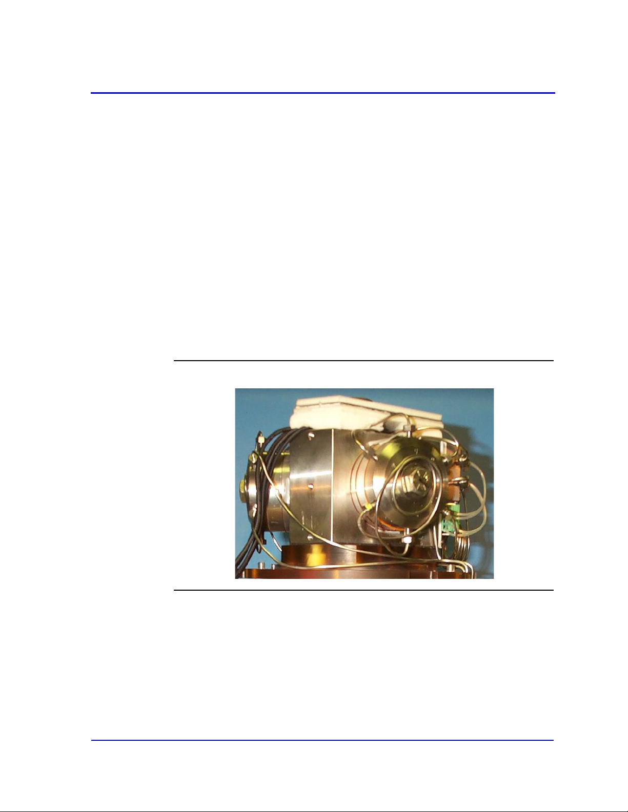
Model 700 Gas Chromatograph System Reference Manual
APRIL 2012 3-9000-521
A more detailed equipment list includes:
• TCD Oven System (consists of the electronics, up to three
chromatograph valves and the stream switching system):
- column module (i.e., “oven”)
- one or two pairs thermal conductivity detectors (TCDs)
- valve system consisting of:
• three sample-directing valves
• plastic manifold that thermally insulates the Oven System and
connects the actuating part to the solenoid valves attached to
the plastic manifold
- two heater zones: column with one cartridge heater and one
block with three heaters
- two thermal cut-off switches:
(oven temperature switch) opens at 257°F (±5 °) (125 °C)
Figure 2-3. TCD Oven System Assembly
•Micro-FID
2 - 3

System Reference Manual Model 700 Gas Chromatograph
Micro-FID
Methanator
ssembly
3-9000-521 APRIL 2012
Figure 2-4. Model 700 Micro-FID upper assembly
The optional flame ionization detector may be used in place of one TCD
for the detection of trace levels of compounds.
•Methanator
Figure 2-5. Model 700 Methanator Upper Assembly
2 - 4

Model 700 Gas Chromatograph System Reference Manual
APRIL 2012 3-9000-521
The optional Methanator, a catalytic converter, converts
otherwise undetectable CO2 and/or CO into methane by adding
hydrogen and heat to the sample.
Figure 2-6. LSIV Assembly
The optional liquid sample inject valve (LSIV) is used to convert a liquid
sample to a gas sample for analysis on the Model 700 Gas
Chromatograph.
A measured sample is placed in a heated chamber above the
vaporization point of the liquid and then it is flashed to a gas. Once
vaporized, the sample is pushed by the carrier gas through the heated
tubing into the column train.
• Stream Switching System (SSS) that consists of the following:
- manifold block
- solenoid valves
- valve clamps
- temperature sensor
- oven temperature switch
- tubing
- insulation cover
2 - 5

System Reference Manual Model 700 Gas Chromatograph
3-9000-521 APRIL 2012
Figure 2-7. SSS Installed
•TCD Electronics
- Dual Methods Adapter Board
- Driver I/O Board
- Multifunction Board
- Preamplifier Board
- External Locking Device
•FID Electronics
- Solenoid/Heater Driver Board
- Multifunction Board
- Preamplifier Power supply
- Driver I/O Board
- Multifunction Board
2 - 6

Model 700 Gas Chromatograph System Reference Manual
WARNING
APRIL 2012 3-9000-521
2.1.2 Lower Enclosure
The Model 700 lower enclosure consists of the Card cage assembly,
which contains the following:
•CPU board
• Com4A board (optional)
• Analog board
• Additional analog board (optional)
•Digital I/O
• Internal modem (optional)
• Ethernet card (optional)
• Field termination board (FTB)
• Connection for AC/DC power supply
(converter)
• Internal and external ground
Note
The Model 700 CSA-certified unit is equipped with 3/4 inch cross-over adapters.
• External locking device
• DB pin connection for serial communications
See power supply label prior to connection. Check the unit power design to determine
if it is equipped for AC or DC power. Applying 110/ 220 VAC to a DC power input unit
will severely damage the unit. Failure to do so may result in injury or death to personnel
or cause damage to the equipment.
2 - 7

System Reference Manual Model 700 Gas Chromatograph
CAUTION
3-9000-521 APRIL 2012
2.1.3 Flow Panel Assembly
The flow panel assembly is attached to the front of the upper enclosure
and consists of the following: (see Figure 2-2):
• Carrier pressure regulator(s) and gauge(s)
•Sample flow meter
•Sample Vent (SV)
•Measure Vent (MV)
• Actuation pressure limiting regulator
• Pressure switch, mounted internally
If the carrier gas pressure drops below a set point, this switch causes the analysis to stop
and activates the analyzer failure alarm.
2 - 8

Model 700 Gas Chromatograph System Reference Manual
APRIL 2012 3-9000-521
2.2 Equipment Specifications
2.2.1 Utilities
Use the following table to determine the utility specifications.
Typ e Specification
unit
dimensions
(P/N 20351)
unit weight • wall mount 130 lbs (59 kg)
materials • 303 and 316 stainless steel
• basic unit envelope
w - 15.2” (387 mm)
h - 41.5” (1054 mm) Note: Allow 14” (360 mm) additional clearance for removal
of dome.
d - 19.2” (488 mm)
•wall mount
w - 18.2” (463 mm)
h - 41.5” (1054 mm)
d - 19.2” (488 mm)
• pole mount
w - 18.2” (463 mm)
h - 41.5” (1054 mm)
d - 25.0” (635 mm)
•floor mount
w - 18.2” (463 mm)
h - 58.0” (1470 mm)
d - 19.2” (488 mm)
• pole mount 135 lbs (61 kg)
• floor mount 150 lbs (68)
• 316 stainless steel and Kapton in contact with sample
• Swagelock and Valco fittings
mounting • floor mount
• pole mount: 2” (60.3 mm); 3” (89.0 mm); 4” (114.3 mm)
• direct wall mount
2 - 9

System Reference Manual Model 700 Gas Chromatograph
3-9000-521 APRIL 2012
Typ e Specification
power • 24VDC standard (24.5 - 26.5 VDC operating voltage range); 80 watts
• AC optional 90-130/180-264 VAC; 47-63 Hz; 80 watts
80 watts start-up; 33 watts nominal
• 47-63Hz (single phase)
• 75W (Model 700 w/TCD)
• 150W (Model 700 w/Methanator or LSIV)
• 36VDC, Sol/Drv PCB Transorb
Note: Voltage range includes line voltage variations. Ensure the GC receives at
least 24.5 VDC at the terminals. If the power supply is located more than 164 feet
(50 meters) from the GC, a voltage drop may occur across the cable and cause the
solenoids to fail. If your GC installation is more than 164 feet (50 meters) away
from the power supply, use an AC power supply to avoid problems with a voltage
drop across the cable.
instrument
air
environment
not required; optional for valve actuation, minimum pressure of 90 psig
• -18 to 55
o
C (0 to 130 oF)
• 0 to 95% RH (non-condensing)
• indoor/outdoor
• pollution - degree 2 (the unit can withstand some non conductive
environmental pollutants e.g., humidity)
• max altitude 2000m
2 - 10

Model 700 Gas Chromatograph System Reference Manual
APRIL 2012 3-9000-521
Typ e Specification
approvals
For USA, Class I, Zone 1, AEx d IIB+H2, T4, Enclosure Type 4
Class I, Division 1, Group B, C and D
For Canada, Class I, Zone 1, Ex d IIB+H2, T4, Enclosure Type 4
Class I, Division 1, Group B, C and D
Gas Chromatograph, Model 700, permanently connected, rated 90-130/180-264 V ac,
75W, 50/60 Hz, I phase, or 23-28 V dc, 75W, Operating Temperature Ambient -18
o
C.
+55
o
C to
0518
SIRA 04ATEX1055X
II 2 G
Ex d IIC T4 Gb
Tamb = +60
IECEx SIR 08.0008X
Ex d IIC T4 Gb
Tamb = 60
o
C
o
C
2 - 11

System Reference Manual Model 700 Gas Chromatograph
3-9000-521 APRIL 2012
2.2.2 Electronic Hardware
Review the system block diagrams, Upper and Lower Electronics, to
become familiar with the Model 700.
Figure 2-8. Upper Electronics with TCD Block Diagram
2 - 12

Model 700 Gas Chromatograph System Reference Manual
PREAMPLIFIER P/S PCB
DC-DC CONVERTERS
24VDC INPUT
OUTPUTS
+20VDC -20VDC
100VDC
5VDC
3.3 VDC
SOLENOID/HEATER
DC-DC CONVERTERS
24 VDC INPUT
OUTPUTS
5VDC
DRIVER PCB
SOLENOID DRIVERS (16)
HEATERS (4 ZONES)
24VDC
PREAMPLIFIER PCB
HEATER PWM CONTROLLER
(4 ZONES)
DIGITAL INPUTS.................(5)
COM RS-232......................(1)
RTD INPUTS.......................(4)
ANALOG INPUTS 4-20mA....(4)
DIGITAL OUTPUTS..............(5)
SERIAL DAC CONTROL.........(SPI)
MULTIFUNCTION
MICRO-CONTROLLER PCB
SERIAL PORT RS-232
SERIAL PERIPHEERAL INTERFACE
POWER
INPUTS:
1 TCD DETECTOR
1 FID DETECTOR
OUTPUTS:
COM (1)
(RS-232 OR RS-485)
SERIAL I/O
APRIL 2012 3-9000-521
Figure 2-9. Upper Electronics with Micro-FID Block Diagram
2 - 13

System Reference Manual Model 700 Gas Chromatograph
3-9000-521 APRIL 2012
Figure 2-10. Lower Electronics TCD Block Diagram
2 - 14

INPUT
AC POWER
OPTIONAL
AC-DC
POWER SUPPLY
24 VDC
FIELD TERMINATION PCB
BUILT IN SURGE PROTECTION
FIELD WIRING FOR THE FOLLOWING:
COM 1 & 2, 5-8
ANALOG INPUTS 4-20mA.......(4)
ANALOG OUTPUTS 4-20mA....(4)
DIGITAL INPUTS.....................(5)
DIGITAL OUTPUTS (5) RELAYS
2 RELAYS FORM “A” CONTACT
3 SOLID STATE RELAYS
ANALYZER INTERCONNECT
POWER FOR STANDARD BUS
DC-DC CONVERTER
OUTPUTS
5VDC, +12VDC, -12 VDC
- 3.8VDC
STD-BUS
OPTIONAL ANALOG
OUTPUT PCB
4 ISOLATED OR
8 NON-ISOLATED
SIGNALS - POWER
CPU
COM4A PCB
COM 5-8
ETHERNET PCB
INTERNAL MODEM
OPTIONAL PC104
BOARD STACK
MULTIFUNCTION COM 3
FID & TCD PREAMPLIFIER COM 4
Model 700 Gas Chromatograph System Reference Manual
APRIL 2012 3-9000-521
Figure 2-11. Lower Electronics Micro-FID Block Diagram
2 - 15

System Reference Manual Model 700 Gas Chromatograph
3-9000-521 APRIL 2012
Use the following table to determine the electronic hardware
specifications.
Typ e Specification
Rating Division 1; no purge required
CPU AMD Geode LX800 500MHz
Memory 128 MB System RAM
CompactFlash 128 MB
Communication Ports 6 configurable Modbus ports; support RS-232/422/485 protocols
Optional Modem 56K Baud Telephone
Analog Inputs 4, 12-pin Phoenix on FTB
Standard Analog Outputs 4, 12-pin Phoenix on FTB
Optional Analog Outputs 8, non-isolated outputs 24-pin Phoenix
Located on Optional Analog Board
Or,
4, isolated outputs 12-pin Phoenix connector
Located on Optional Analog Board
Discrete Digital Inputs GC_IN (dedicated to pressure switch); 4 user-defined inputs
Digital Outputs (5) 2 Relays “Form A” contacts
Relay contact rating 24 VDC nominal @ 1 Amp
3 Solid State Relays - Rating of 0.375A @30 VDC on FTB - 10 pin
Phoenix connector
Detector Inputs Optionally 2 micro-volume TCD inputs
1 Flame Ionization Detector (Micro-FID) input
Transient Protection over-voltage category II
2 - 16

Model 700 Gas Chromatograph System Reference Manual
APRIL 2012 3-9000-521
2.2.3 Micro Heat Sink Oven
Use the following table to determine the oven specifications.
Typ e Specification
Valves 6-port and 10-port valves; piston-operated diaphragms
with pneumatic actuation
Columns max of 40 feet (12 m) of micro-packed columns; 1/16-
inch
(1.6-mm) outside diameter
Solenoid Actuation • 24 VDC
• max 90 psi
Wetted Parts 316 stainless steel and kapton diaphragm
Temperature Control • 24 VDC heat sink
•2 zones (1 column, 1 block)
• max operating temperature of 115 °C (239 °F)
Sample System 1 zone, includes Stream Switching System
Sample Streams • standard: max of 3 analytical and 1 auto calibration
•optional: max of 8
2 - 17

System Reference Manual Model 700 Gas Chromatograph
3-9000-521 APRIL 2012
2.2.4 Software
Use the following table to determine the software specifications.
Note
The Model 700 has its own applications and is not compatible with 2350/2350A
applications.
Typ e Specification
Software PC-based MON2000; runs 2350 and 2350A applications (v2.4
or later)
Firmware embedded firmware compatible with 2350/2350A
applications (v1.8 or later)
Methods 4 Timed Event Tables and 4 Component Data Tables
assignable to each stream
Peak Integration • fixed time or auto slope and peak identification
• update Retention Time upon
calibration or during analysis
2 - 18

Model 700 Gas Chromatograph System Reference Manual
This page is intentionally left blank.
APRIL 2012 3-9000-521
2 - 19

System Reference Manual Model 700 Gas Chromatograph
3-9000-521 APRIL 2012
2 - 20

3-
WARNING
Section 3: Installation and setup
This section provides instructions for installing and setting up the Model
700 gas chromatograph (GC) system for Zone 1/ Division I
environments.
This procedure involves the following steps:
• Observe precautions and warnings
•Plan site location
• Obtain supplies and tools
• Install GC wiring
• Install GC sample and gas lines
• Perform leak checks
• Purge carrier gas lines
• Purge calibration lines
• Start up GC system
3.1 Precautions and warnings
Install and operate all equipment as designed and is compliant with all safety
requirements. The “Seller” does not accept any responsibility for installations of the
Model 700, or any attached equipment, in which the installation or operation thereof
has been performed in a manner that is negligent and/or non-compliant with
applicable safety requirements.
3 - 1

System Reference Manual Model 700 Gas Chromatograph
WARNING
WARNING
WARNING
WARNING
3-9000-521 APRIL 2012
3.1.1 Hazardous environments
Observe all precautionary signs posted on the Model 700 enclosure. Failure to do so
may result in injury or death to personnel or cause damage to the equipment.
Observe all precautionary signs posted on the Model 700 enclosure.
The Model 700 enclosures are certified by CSA for Class I, Zone 1, Ex d IIB+H2 T4,
Enclosure Type 4 and Class I, Division 1, Groups B,C,D. The Model 700 enclosures are
certified by ATEX for ATEX Ex d IIC T4 and IEC-Ex Ex dIIC T4.
ATEX certified units must be installed strictly in compliance with the requirements of
IEC 60079-14.
Special conditions for safe use must be met. The maximum constructional gap (i
less than that required by Table 2 of EN 60079-1:2007.
Before opening the Model 700 enclosure, reduce the risk of igniting hazardous
atmospheres by disconnecting the equipment from all power supplies. Keep the
assembly closed tightly when in operation to reduce the risk of igniting hazardous
atmospheres. Inlet (incoming) wiring must meet local standards (i.e. in conduit with
seal fitting within 18 or via cable glands certified to IEC 60079-1). Upper enclosure
threaded entry is ¾ NPT. Lower enclosure threaded entries are M32-1.5.
Observe all precautionary signs posted on the Model 700 enclosure. Failure to do so
may result in injury or death to personnel or cause damage to the equipment.
Please direct all health, safety and certification related questions to: Emerson Process
Management, Gas Chromatographs, Applications Engineering Group, 713-827-6380 or
1-866-GC Center (1-866-422-3683).
c
) is
3 - 2

Model 700 Gas Chromatograph System Reference Manual
CAUTION
APRIL 2012 3-9000-521
Follow these precautions if installing or operating the Model 700
instrumentation in a hazardous area:
1. Install and operate only the Zone 1/ Division I version of the
Model 700 in a hazardous area.
2. Do not operate any printer or personal computer (PC) that is
connected to a GC which is installed in a hazardous area. To
interface with a GC in a hazardous area, use a PC that is located in
a nonhazardous area and remotely connected to the GC.
3. Ensure that field connections to the analyzer are made through
explosion-proof conduit or flameproof glands.
3.1.2 Power source wiring
Follow these precautions when installing AC power source wiring:
1. All wiring must conform to the CEC or NEC, local state or other
jurisdiction, and company standards and practices.
2. Provide 24 VDC (24.5 - 26.5 VDC range) power or optional singlephase, 3-wire, power at 115 or 230 VAC, 47-63 Hertz.
3. Locate circuit breaker and optional power disconnect switch in a
safe area.
4. Provide the Model 700 system and any optionally installed
devices with one 15-Amp circuit breaker for protection.
15 amps is the maximum current for 14 AWG (wire).
5. Ensure that the 24 VDC input power is S.E.L.V. compliant by
suitable electrical separation from other circuits.
3 - 3

System Reference Manual Model 700 Gas Chromatograph
3-9000-521 APRIL 2012
6. Use multi-stranded copper conductor wire according to the
following recommendations:
• For power feed distances up to 250 feet (76 meters), use 14
AWG (American Wire Gauge) (18 Metric Wire Gauge),
stranded.
• For power feed distances 250 to 500 feet (76 to 152 meters),
use 12 AWG
(25 Metric Wire Gauge), stranded.
• For power feed distances 500 to 1000 feet (152 to 305
meters), use 10 AWG
(30 Metric Wire Gauge), stranded.
• Cable entries are M32 in accordance with ISO 965.
3.1.3 Card cage removal
The Model 700 card cage assembly is designed to be disconnected and
removed from the lower enclosure to allow space for user power and
signal connections. This may be particularly important for applications
where large numbers of I/O connections are required.
Note
Card cage removal is not necessary for I/O connections.
To disassemble the card cage, do the following:
1. Remove the lower enclosure cover and the front flow panel
assembly or LOI.
3 - 4

Model 700 Gas Chromatograph System Reference Manual
Cover
LOI
APRIL 2012 3-9000-521
Figure 3-1. Lower enclosure disassembly
If removing a flow panel assembly, leave the wires attached to it
and allow it to hang outside of the enclosure.
2. Carefully disconnect all of the ribbon cables from the boards in
the card cage assembly (CPU, Analog, Modem, etc.).
Note
Note the location of the ribbon cables for ease of reassembly.
3 - 5

System Reference Manual Model 700 Gas Chromatograph
Flow Panel
3-9000-521 APRIL 2012
Figure 3-2. Card cage cable disassembly
3 - 6
3. Use a Phillips head screw driver and remove the two screws
located at the top of the card cage and one screw on the bottom
left side of the card cage (not visible in the figure).

Model 700 Gas Chromatograph System Reference Manual
Card Cage
Screws
APRIL 2012 3-9000-521
Figure 3-3. Card cage assembly screw locations
4. Slide the card cage assembly out of the lower enclosure.
3 - 7

System Reference Manual Model 700 Gas Chromatograph
3-9000-521 APRIL 2012
Figure 3-4. Card cage disassembly
3 - 8
5. User power and signal connections may be made with the card
cage removed from the lower enclosure.

Model 700 Gas Chromatograph System Reference Manual
APRIL 2012 3-9000-521
Figure 3-5. Card cage disassembly for power and signal wiring
3 - 9

System Reference Manual Model 700 Gas Chromatograph
CAUTION
3-9000-521 APRIL 2012
3.1.4 Signal wiring
Follow these general precautions for field wiring digital and analog
input/output (I/O) lines:
Observe all precautionary signs posted on the Model 700 enclosure. Applicable to all
digital and analog I/O lines connecting to the GC: Any loop of extra cable left for service
purposes inside the GC housing must not be placed near any AC power lines. If this
precaution is not followed, the data and control signals to and from the GC can be
adversely affected.
• Metal conduit must be used for all process signal wiring (assuming
operation in a Class 1, Division 1 Explosive Area). Metal conduit is not
required for use in general purpose areas.
• Metal conduit or cable (in compliance with EN 60079-14) used for
process signal wiring must be grounded at conduit support points
(intermittent grounding of conduit helps prevent induction of
magnetic loops between the conduit and cable shielding).
• All process signal wiring should be a single, continuous length
between field devices and the GC. If, however, length or conduit runs
require that multiple wiring pulls be made, the individual conductors
must be interconnected with suitable terminal blocks.
• Use suitable lubrication for wire pulls in conduit to prevent wire
stress.
• Use separate conduits for AC voltage and DC voltage circuits.
• Do not place digital or analog I/O lines in same conduit as AC power
circuits.
• Use only shielded cable for digital I/O line connections.
- Ground the shield at only one end.
- Shield-drain wires must not be more than two AWG sizes smaller
than the conductors for the cable.
• When inductive loads (relay coils) are driven by digital output lines,
the inductive transients must be diode-clamped directly at the coil.
• Any auxiliary equipment wired to the GC must have its signal
common isolated from earth/chassis ground.
3 - 10

Model 700 Gas Chromatograph System Reference Manual
APRIL 2012 3-9000-521
3.1.5 Electrical and signal ground
Follow these general precautions for grounding electrical and signal
lines:
• For shielded signal conducting cables, shield-drain wires must not be
more than two AWG sizes smaller than the conductors for the cable.
Shielding is grounded at only one end.
• Metal conduit used for process signal wiring must be grounded at
conduit support points (intermittent grounding of conduit helps
prevent induction of magnetic loops between the conduit and cable
shielding).
• A single-point ground (the outside case ground lug) must be
connected to a copper-clad, 10-foot long, 3/4-inch diameter steel
rod, which is buried, full-length, vertically into the soil as close to the
equipment as is practical (note: the grounding rod is not furnished.)
3 - 11

System Reference Manual Model 700 Gas Chromatograph
Ground Lug
Inside Lower
Enclosure
Ground Lug
Outside Lower
Enclosure
3-9000-521 APRIL 2012
Figure 3-6. Ground Lug Lower Enclosure
3 - 12
• Resistance between the copper-clad steel ground rod and the earth
ground must not exceed 25 Ohms.
• On ATEX certified units, the external ground lug must be connected
to the customer’s protective ground system via AWG 9 (6mm2)
ground wire. After the connection is made, apply a non-acidic grease
to the surface of the external ground lug to prevent corrosion.
• The equipment-grounding conductors used between the GC and the
copper-clad steel ground rod must be sized according to the
following specifications:
Length Wire
15 ft. (4.6 m) or less 8 AWG
stranded, insulated copper

Model 700 Gas Chromatograph System Reference Manual
APRIL 2012 3-9000-521
Length Wire
15 to 30 ft. (4.6 to 9.1 m) 6 AWG
stranded, insulated copper
30 to 100 ft. (9.1 to 30.5 m) 4 AWG
stranded, insulated copper
• All interior enclosure equipment-grounding conductors must be
protected by metal conduit.
• External equipment, such as data printers, that are connected to the
GC should be powered via isolation transformers to minimize the
ground loops caused by the internally shared safety and chassis
grounds.
3.1.6 Electrical conduit
Follow these general precautions for conduit installation:
• Conduit cutoffs must be square. Cutoffs must be made by a cold
cutting tool, hacksaw, or by some other approved means that does
not deform the conduit ends or leave sharp edges.
• All conduit fitting-threads, including factory-cut threads, must be
coated with a metal-bearing conducting grease, such as CrouseHinds STL or equivalent, prior to assembly.
• Temporarily cap the ends of all conduit runs immediately after
installation to prevent accumulation of water, dirt, or other
contaminants. If necessary, swab out conduits prior to installing the
conductors.
• Install drain fittings at the lowest point in the conduit run; install seals
at the point of entry to the GC explosion-proof housing to prevent
vapor passage and accumulation of moisture.
• Use liquid-tight conduit fittings, such as Myers Scru-tite or similar, for
conduits exposed to moisture.
When conduit is installed in hazardous areas (e.g., areas classified as NEC
Class I, Division 1, Groups B, C, and D), follow these general precautions
for conduit installation:
3 - 13

System Reference Manual Model 700 Gas Chromatograph
WARNING
3-9000-521 APRIL 2012
Observe all precautionary signs posted on the equipment. Consult your company
policies and procedures and other applicable requirements documents to determine
wiring and installation practices that are appropriate for hazardous areas. Failure to do
so may result in injury or death to personnel or cause damage to the equipment.
• All conduit runs must have a fitting, which contains explosion-proof
sealing (potting) located within 18 inches from the conduit entrance
to the explosion-proof housing.
• The conduit installation must be vapor tight, with threaded hub
fittings, sealed conduit joints and gaskets on covers, or other
approved vapor-tight conduit fittings.
3.1.7 Sample system requirements
Observe the following guidelines for installing GC sample systems:
Line length:
If possible, avoid long sample lines. In case of a long sample line, flow
velocity can be increased by decreasing downstream pressure and using
by-pass flow via a speed loop.
Note
Stream switching requires a sample pressure of 20 psig.
Sample line tubing material:
Note
The calibration gas stream inlet is the last stream inlet following the sample gas.
• Use stainless steel tubing for noncorrosive streams.
• Ensure tubing is clean and free of grease (see Figure 3-7 for details).
3 - 14

Model 700 Gas Chromatograph System Reference Manual
Gas Connections
Stream 1 - 8
APRIL 2012 3-9000-521
Figure 3-7. Stream Inlets (Right side of unit)
Dryers and filters:
Use small sizes to minimize time lag and prevent back diffusion.
Note
Install the probe/regulator first, immediately followed by the coalescing filter and then
the membrane filter. See Appendix C for a recommended natural gas installation.
• Install a minimum of one filter to remove solid particles. Most
applications require fine-element filters upstream of the GC. The
Model 700 hardware includes a 2-micron filter.
• Do use ceramic or porous metallic type filters. Do not use cork or felt
filters.
3 - 15

System Reference Manual Model 700 Gas Chromatograph
3-9000-521 APRIL 2012
Pressure regulators and flow controllers:
• Do not use types containing cork or felt filters, or absorbent
diaphragms.
Pipe Threads, dressing:
• Do use Teflon tape. Do not use pipe thread compounds (dope).
Valving:
• Install a block valve downstream of sample takeoff point for
maintenance and shutdown.
• Block valve should be needle valve or cock valve type, of proper
material and packing, and rated for process line pressure.
3.2 Preparation
Your Model 700 GC was started and checked out before it left the
factory. Program parameters were installed and documented in the PC
Config Report furnished with your Model 700.
3.2.1 Site selection
Install the GC as close as possible to the sample system but allow for
adequate access space for maintenance tasks and adjustments. Allow a
minimum of 14 inches (36 cm) in front for enclosure opening and access.
• Allow a minimum of 14 inches (36 cm) above the top of the dome
enclosure for dome removal and access.
• Ensure that exposure to radio frequency (RF) interference is minimal.
3 - 16

Model 700 Gas Chromatograph System Reference Manual
APRIL 2012 3-9000-521
3.2.2 Unpacking the unit
See the following checklist for unpacking the unit and inspecting for
damage:
1. Unpack the equipment:
• Model 700 system
• MON2000 CD-ROM
2. Ensure that all documentation and software are included on the
CD-ROM:
• This manual: Model 700 Gas Chromatograph System Reference
Manual (P/N 3-9000-521)
• The software manual: MON2000 Software for Gas
Chromatographs User Manual (P/N 3-9000-522)
• The MON2000 Software for Gas Chromatographs Windows
application, Modbus Test application, and GC applications
(P/N 2-3-2350-400)
3. Remove any packing materials from internal areas of the unit
(particularly in the dome enclosure).
4. If an FID is present, remove the vent plug from the FID outlet. The
vent plug has a tag attached to it that reads “REMOVE VENT
PLUGS PRIOR TO OPERATION”. Failure to remove the cap could
result in a performance failure or in damage to the detector.
Installation and startup should proceed only if all required materials are
on hand and free from obvious defects.
If any parts or assemblies appear to have been damaged in shipment,
first file a claim with the carrier. Next, complete a full report describing
the nature and extent of the damage and forward this report
immediately to Measurement Services for further instructions (see the
Customer Repair Report at the back of this manual). Include complete
model number information. Disposition instructions will be returned
immediately.
3 - 17

System Reference Manual Model 700 Gas Chromatograph
3-9000-521 APRIL 2012
3.2.3 Model 700 installation arrangements
The Model 700 GC can be ordered for installation in the following
mounting arrangements (see drawing P/N DE-20993):
Note
The wall should be strong enough to support the 200-pound load.
•Wall mount
•Pole mount
•Floor mount
3.2.3.1 Wall mount
The simplest arrangement is wall mount (see drawing P/N DE-20993).
The unit has two mounting ears on each side. The ear-holes are used to
attach the unit to a wall.
The uppermost of the holes should be about 30 inches from the floor for
the most efficient use of the unit.
The space between the enclosures and the wall (1.3 inches) allows
adequate access above and around the unit.
3.2.3.2 Pole mount
The pole mount arrangement uses mounting ears as attachment points
for the plates clamped to a pole (see drawing P/N DE-20993). The plates
accept the recommended u-bolt systems for the 2 inch, 3 inch or 4 inch
nominal pipe sizes. The base attachment of the pole being used must be
able to accommodate the weight of the unit.
3 - 18

Model 700 Gas Chromatograph System Reference Manual
APRIL 2012 3-9000-521
3.2.3.3 Floor mount
The floor mount arrangement includes additional external framing that
creates a free-standing unit (see drawing P/N DE-20993). The mounting
ears, located on the base of the frame, are used to anchor the unit to a
floor or instrument pad. The frame, also provides a means for attaching
sample-conditioning plates or for anchoring
tubing-runs.
3.2.4 Required Tools and Components
You will need these tools and components to install the Model 700:
• Zero grade carrier gas (99.995% pure, with less than 5 ppm water,
and less than 0.5 ppm hydrocarbons)
• High pressure dual-stage regulator for the carrier gas cylinder, high
side up to 3000 pounds per square inch, gauge (psig), low side
capable of controlling pressure up to 150 psig
• Calibration standard gas with correct number of components and
concentrations. See Appendix Table C-1.
• Single-stage regulator for the calibration gas cylinder, low pressure
side capable of controlling pressure up to 30 psig
• Sample probe regulator (fixture for procuring the stream, or sample
gas for chromatographic analysis)
• Coalescing filter
• Membrane filter
• 1/8-inch stainless steel (SS) tubing for connecting calibration
standard to GC, 1/8 inch SS tubing for connecting carrier gas to the
GC, 1/8-inch SS tubing for connecting stream gas to the GC
• Heat tracing (as required) for sample transport and calibration lines
• Miscellaneous Swagelok tube fittings, tubing benders and tubing
cutter
• 14 AWG (18 MWG) or larger electrical wiring and conduit to provide
115 or 230 volts AC, single phase, 50 to 60 Hertz, from an
appropriate circuit breaker and power disconnect switch. See
guidelines in “Power source wiring” on page 3-3.
• Liquid leak detector (Snoop® or equivalent)
3 - 19

System Reference Manual Model 700 Gas Chromatograph
WARNING
3-9000-521 APRIL 2012
• Digital volt-ohm meter with probe-type leads
• Flow measuring device
• Open-end wrenches sized 1/4, 5/16, 7/16, 1/2, 1/16 and 5/8-inch
3.2.5 Supporting tools and components
Do not use a PC or a printer in a hazardous area. Serial port and Modbus
communications links are provided to connect the unit to the PC and to connect to
other computers and printers in a safe area. Failure to follow this warning may result in
injury or death to personnel or cause damage to the equipment.
Supporting tools and components include:
• Use an IBM-compatible PC and either a direct or remote
communications connection to interface with the Model 700 system.
See Section 2.1 of the MON2000 Software for Gas Chromatographs
User Manual
(P/N 3-9000-522) for more information on specific PC requirements.
• The Model 700 comes with serial Port 2 on the Field Termination
Board (FTB) factory-wired with a DB 9-pin connection. Use the
provided serial cable (P/N 3-2350-068) to hookup to a PC. See Table
A-4 for more information regarding these connections.
Note
You can use the serial cable installed for the Model 700. For straight-through serial
cable installation and fabrication instructions, see Appendix A.
If a different serial cable is used to connect from the PC to the prewired DB 9-pin, follow these specifications:
Ter mi na l Connection
DB 9-pin male Serial Port 2
DB 9-pin male
DB 25-pin female
PC serial port
3 - 20

Model 700 Gas Chromatograph System Reference Manual
WARNING
CAUTION
APRIL 2012 3-9000-521
• Use items necessary for connecting the GC to a network or other
type of remote data transfer system (an example item might be an
RS-232/RS-485 conversion box for long distance serial transmission),
as applicable.
• Use a printer, connected either at the PC or the GC unit, to record
analysis and other data. See Section 3.4.6 for wiring information.
3.3 Model 700 installation
3.3.1 DC power supply
Ensure that the DC power source is switched OFF before connecting the wires. Also,
ensure that the DC power is S.E.L.V. compliant by suitable electrical separation from
other circuits. Failure to follow these warnings may result in injury or death to personnel
or cause damage to the equipment.
Check the unit prior to wiring to determine if it is equipped for DC power. Failure to
observe this precaution may damage equipment.
To connect DC power to the GC:
1. Locate the plug-together termination block inside the lower
enclosure.
3 - 21

System Reference Manual Model 700 Gas Chromatograph
24 VDC Power Connection
3-9000-521 APRIL 2012
Figure 3-8. 24 VDC power connection
2. Bring the two leads in through the entry on the left side of the
lower enclosure. Connect to the termination plug provided with
the unit. See Appendix H Drawing DE- 20993.
3 - 22

Model 700 Gas Chromatograph System Reference Manual
24 VDC Power Inlet
APRIL 2012 3-9000-521
Figure 3-9. 24 VDC power inlet
Use the following table for the DC power wiring details:
Attribute Wire Color
+ (positive) red
— (negative) black
3. Each board that connects to the 24 VDC is protected from lead
reversal by the use of blocking diodes. The following boards are
connected to the 24 VDC:
• Field Termination Board
• Isolated Analog Output Option Board
• Solenoid/Heater Driver board
Note
A new version of the Solenoid/Heater Driver Board that includes the Diode protection
will soon be released.
• FID/TCD Preamplifier Board
If the Red (+) and Black (-) leads are inadvertently reversed, no
damage will occur, however, the system will not have power.
3 - 23

System Reference Manual Model 700 Gas Chromatograph
WARNING
AC / DC Power
Converter
3-9000-521 APRIL 2012
4. Connect the DC power leads to the power disconnect switch that
is properly fused. The recommended fuse size is 10 Amps.
3.3.2 Optional AC — DC power converter
To connect 115 or 230 VAC power to the GC:
Check the unit prior to wiring to determine if it is equipped for optional AC power.
Failure to follow this warning may result in injury or death to personnel or cause
damage to the equipment.
1. Locate the plug-together termination block inside the lower
enclosure (located on the lower left side behind the power
supply).
Figure 3-10. AC/DC Power Converter
3 - 24

Model 700 Gas Chromatograph System Reference Manual
WARNING
CAUTION
APRIL 2012 3-9000-521
Do not connect AC power leads without first ensuring that AC power source is switched
OFF. Failure to follow this warning may result in injury or death to personnel or cause
damage to the equipment.
Do not apply electrical power to the GC until all interconnections and external signal
connections have been verified, and proper grounds have been made. Failure to
observe this precaution may cause damage to equipment.
AC wiring is usually colored as:
Attribute Wire Color
hot brown or black
neutral blue or white
ground green or green
2. Bring the power leads in through the left entry on the bottom of
the enclosure.
3. If necessary, connect the GC chassis ground to an external copper
ground rod (at remote locations). See Section 3.1.5 regarding
electrical and signal grounding.
3 - 25

System Reference Manual Model 700 Gas Chromatograph
MV
SV
Sample Vent and
Measure Vent Lines
3-9000-521 APRIL 2012
3.3.3 Sample and Gas Lines
To install GC sample and gas lines:
Note
Use SS tubing. Keep tubing clean and dry internally to avoid contamination. Before
connecting the sample and gas lines, flow clean air or gas through them. Blow out
internal moisture, dust, or other contaminants.
1. Remove the plug from the Sample Vent (SV) line (1/16-inch
tubing marked “SV” located on the Flow Panel Assembly).
• If desired, connect the SV line to an external (ambient
pressure) vent. If the vent line is terminated in an area exposed
to wind, protect the exposed vent with a metal shield.
• Use 1/4-inch or 3/8-inch tubing for vent lines longer than 10
feet.
Figure 3-11. Model 700 Upper Enclosure
Note that, at this stage in the installation, the GC Measure Vent
(MV) line (marked “MV”) remains plugged until leak checks are
completed. For regular operation, however, the MV line must be
unplugged, or open.
Do not discard the vent line plugs. They are useful at any time
when leak-checking the GC and its sample or gas line
connections.
3 - 26

Model 700 Gas Chromatograph System Reference Manual
CAUTION
Carrier Gas
Inlet
APRIL 2012 3-9000-521
2. Connect carrier gas to the GC. (The carrier gas inlet is a 1/8-inch
tee fitting located on the left side of the upper enclosure.)
Do not turn on gas until you have completed leak checking the carrier and sample lines
(see Step 5). Failure to follow this precaution may cause injury to personnel or damage
equipment.
Figure 3-12. Carrier gas inlet left-side upper enclosure
• Use 1/8-inch or 1/4-inch stainless steel tubing to conduct
carrier gas.
• Use a dual-stage regulator with high-side capacity of 3000
psig and low-side capacity of 150 psig.
3 - 27

System Reference Manual Model 700 Gas Chromatograph
3-9000-521 APRIL 2012
• See Appendix C for a description of a dual-cylinder carrier gas
manifold (P/N 3-5000-050) with these features:
Note
The first stream is the calibration gas stream.
- Carrier gas is fed from two bottles.
- When one bottle is nearly empty (100 psig), the other
bottle becomes the primary supply.
- Each bottle can be disconnected for refilling without
interrupting GC operation.
3. Connect calibration standard gas to the GC
Note
When installing the calibration standard gas line, ensure that the correct
tubing connection is made.
• Use 1/8-inch stainless steel tubing to conduct calibration
standard gas.
• Use a single-stage regulator with low-side capacity of up to 30
psig.
• The calibration gas inlet is the last inlet following the sample
gas.
3 - 28

Model 700 Gas Chromatograph System Reference Manual
Gas Inlet
Calibration
APRIL 2012 3-9000-521
Figure 3-13. Calibration gas stream inlet (right side of unit)
4. Connect sample gas stream(s) to the GC (see Figure 3-11 Model
700 Upper Enclosure panel).
• Use 1/8-inch or 1/4-inch stainless steel tubing to conduct
calibration standard gas.
• Ensure that pressure of sample line is regulated to maintain 15
to 30 psig (±10%).
• Gas stream inlet(s) are identified (see Figure 3-14) for details.
3 - 29

System Reference Manual Model 700 Gas Chromatograph
Streams 1 - 7
Gas Inlets
Gas Inlet
Calibration
3-9000-521 APRIL 2012
Figure 3-14. Sample stream inlets (Right side of unit)
5. After all lines have been installed, proceed with leak checking the
carrier and sample lines. See Section 3.5.1; note that it requires
the AC power to be turned on at the GC.
3.4 Setting the Com ID
The Model 700 Com ID is determined by dual inline package (DIP) switch
settings.
Note
Follow the steps in this section only if you wish to change the Com ID setting or visually
inspect and verify the DIP switch settings.
3 - 30

Model 700 Gas Chromatograph System Reference Manual
CAUTION
APRIL 2012 3-9000-521
Figure 3-15. Dip switch
In most cases, the Com ID configuration made at the factory will not
need to be changed. The factory DIP switch settings produce a Com ID of
1.
3.4.1 Inspect or change the Com ID
To visually inspect and verify the DIP switch settings or to change the
Com ID settings on the multifunction board,
1. Remove the dome from the upper enclosure.
Use caution when accessing an enclosure. A voltage of 115 to 230 VAC, along with
various DC voltages, are present. Failure to follow this precaution may cause injury to
personnel or damage equipment.
2. Loosen the thumb screws on the oven system mounting plate.
Note
Note that MON2000 Com I.D. settings will override the hardware settings. To
use the hardware Com I.D. configuration, enter a zero in the MON2000 Com
I.D. settings. For details, refer to MON2000 Software for Gas Chromatographs
User Manual (P/N 3-9000-522).
3. Carefully lift up the assembly and rotate so that the enclosure
opening is accessible.
3 - 31

System Reference Manual Model 700 Gas Chromatograph
Mounting Bracket
Thumb Screw
Multifunction
Board
3-9000-521 APRIL 2012
Figure 3-16. Oven Mounting Bracket
4. Locate the multifunction board. It is mounted on a bracket
towards the center of the upper enclosure.
Figure 3-17. Multifunction Board Location
3 - 32

Model 700 Gas Chromatograph System Reference Manual
APRIL 2012 3-9000-521
5. On the multifunction board, locate the Modbus slave address
(Com ID) DIP switch. It is labeled “S1” and mounted on the lower
right corner of the board.
Figure 3-18. Dip Switch
6. Inspect or change the DIP switch as necessary, using the wiring
diagram as a guide. See Tabl e 3 -1 .
• Make settings on switch S1 located on the multifunction
board.
• Switches “1” through “5” form a 5-bit binary number for
setting the Modbus slave address (also known as Com ID or
Device ID).
• Switch number “1” is the least significant bit, and switch
number “5” is the most significant bit. Set these switches
either ON or OFF.
• Switch “6” and “7” are spares and switch “8” is used to cold
start the processor. See Tab le 3- 2.
3 - 33
 Loading...